1
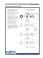
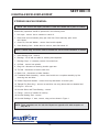
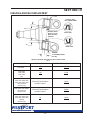
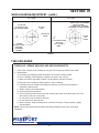
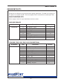
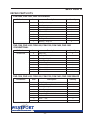
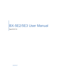
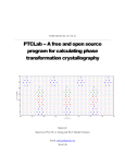
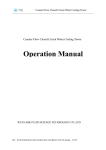
I-BEAM & TUBULAR
STEERABLE AXLES
FRONT AXLE
PUSHER & TAG
SERVICE MANUAL
ISO 9001
INDEX
THIS MANUAL COVERS THE FULL LINE OF WESTPORT AXLES.
Section
Description
Page No.
Section IV
General Repair/Replacement ................................ 13-22
1. General Precautions/Inspections ..................... 13-15
2. King Pin & Knuckle ........................................... 16-18
3. Tie Rod End .......................................................... 19
4. Wheel Bearing.................................................. 20-21
5. Tube Axle Repair ................................................... 21
Section V
Repair Kits............................................................. 22-24
1. All Kingpin Kits - Conventional or Sealed ......... 22-24
2. Knuckle Kits ............................................................ 24
3. Tie Rod Ends.......................................................... 24
-2-
Rev. 1/2/00
SECTION IV
GENERAL REPAIR / REPLACEMENT
a.
Cleanliness is very important
when making repairs. Provide a
clean place to work.
b.
When assembling, apply an ample
quantity of lubricant to bearing
surfaces and king pins.
c.
For safety purposes, use
stationary jacks under axle when
removing wheels. Do not allow
weight to rest on a hydraulic jack
for any length of time.
d.
Use only suitable solvent, such
as kerosene, to wash parts.
Thoroughly dry all parts
immediately after cleaning.
e.
The tool, illustrated in Figure 1,
should always be used when
installing new knuckle bushings to
prevent collapse or distortion of
bushings.
FIG. 1- BUSHING REMOVING AND
INSTALLING TOOL
F4W-0800
F5W-0900
F5W-1000
F5W-1200
F3W-1300
F3W-1400
F3W-1600
F6W-1300
F6W-1400
F6W-1600
F3W-2000
F3W-2000D
MAKE LOCALLY FROM BAR STOCK
- 13 -
Rev. 1/2/00
SECTION IV
GENERAL REPAIR / REPLACEMENT
BASIC INSPECTION
1. Inspect all front axle fasteners for looseness. If loose, retorque to proper value. If worn,
replace.
2. Inspect axle parts for wear or damage, bent or cracked. If detected - replace.
3. Make certain parts move freely through axle turn.
4. Inspect for tire wear patterns.
VERTICAL END - PLAY OF STEER KNUCKLE
1. Raise vehicle off the ground. Support with jack stands.
2. With a dial indicator place magnetic base on I-beam. Place pointer end of indicator on
upper king pin grease cap.
3. Pry the knuckle “DOWN”.
4. Set dial indicator to “ZERO”.
5. Pry the knuckle “UP”.
6. Reading must be between .002 - .010 inch
7. If “ZERO”, remove shims. If reading exceeds .025, Inspect thrust bearing. Replace, if
necessary, readjust using shims.
KING PIN BUSHING INSPECTION
1. Raise vehicle off the ground. Support with jack stands.
2. With a dial indicator place magnetic base on I-beam. Place pointer end of indicator against
upper steer arm lobe of knuckle. Zero indicator.
3. Move tire/wheel in and out with a push pull motion.
4. If dial indicator reads .010 inch or more, king pin bushings need replacement.
5. Repeat process for lower bushing.
6. If either bushing indicates wear, replace both.
- 14 -
Rev. 1/2/00
SECTION IV
GENERAL REPAIR / REPLACEMENT
TIE ROD END INSPECTION
1. Grab crosstube to move in any direction. If any movement or looseness is detected,
replace tie rod ends.
WHEEL BEARING INSPECTION
1. Remove bearings.
2. Clean bearings and spindle with a suitable solvent.
3. Inspect rollers cups, and cones for wear, pitting or chipped condition.
4. If detected - replace bearings.
5. Inspect spindle for worn, damaged, or discolored/burnt condition on bearing surfaces.
6. If detected - replace knuckle.
7. If water or other contaminates are found in the wheel cavity — replace oil seal.
8. If oil is detected on brake shoes or brake drum area — replace oil seal.
TUBE AXLE INSPECTION
1. Inspect welds on tube axles with regards to add on brackets, axle seats, etc., for weld
cracks or broken welds.
2. If the crack or break extends into the tube axle, do not repair. Replace axle tube.
3. If the crack or break is only in the weld, refer to the weld repair section.
- 15 -
Rev. 1/2/00
SECTION IV
KING PIN & KNUCKLE REPLACEMENT
STEERING KNUCKLE REMOVAL
NOTE: This service and repair procedure is with axle I-beam left in place on vehicle.
Disassembly operations should be performed in the following order:
1. Hub caps - remove. Use a container to catch oil.
2. Raise front end until wheels (tires) just clear floor. Place stationary jacks under
axle I-beam.
3. Cotter Pin, Nut and Washer - remove from knuckle spindle.
4. Outer Bearing Cone - shake wheel to remove; then slide wheel off.
NOTE: A wheel dolly should be used to facilitate the removal and installation of wheels.
5. Inner Bearing Cone - remove.
6. Bearings - lift off and set aside for cleaning and inspection.
7. Bearings Cups - if necessary remove from wheel hub.
8. Oil Seal - remove from spindle.
9. Drag Link- disconnect at steering knuckle upper arm.
10. Tie Rod - disconnect at knuckle lower arm.
11. Brake Line - disconnect at brake chamber.
12. Foundation Brake Assembly - remove from knuckle as a complete assembly by first
removing nuts and bolts.
13. Grease Caps and Gaskets - remove from top and bottom of knuckle yoke.
14. Tapered Pin (Draw Key) - remove nut and drive out using bronze drift on threaded end.
15. King Pin - drive out.
16. Knuckle Shims and Thrust Bearing - remove.
17. Fittings - remove (If installed in knuckle).
18. Knuckle Bushing Seal - remove.
19. Knuckle Bushings - if worn, remove, using tool as shown in Figure 1.
NOTE: These operations are for left side. Repeat on opposite side with exception of
Step No. 9.
- 16 -
Rev. 1/2/00
SECTION IV
KING PIN & KNUCKLE REPLACEMENT
STEERING KNUCKLE INSTALLATION
1. Knuckle Bushings - conventional bolt on cap - align lube holes on bushings with holes in
knuckle. Press bushings in. Holes in knuckle and bushing must be in-line. Use installation
tool shown in Figure 1, page 13 for this operation.
1a. Knuckle Bushings - sealed screw-in cap - press bushings to dimensions shown. Use
installation tool shown in Figure 1, page 13 for this operation.
2. Ream Bushings to dimensions shown in Figure 2, page 18. Clean bore of shavings.
3. Install king pin seals. See Figure 2, page 18.
4. Install lube fittings. (If steer knuckle has provision).
5. Position and support knuckle on axle.
6. Install thrust bearing - between lower face of I-beam and lower leg of steer knuckle. The
seam created by the top and bottom half of the thrust bearing should point toward the
ground.
7. Align holes of knuckle, I-beam and thrust bearing.
8. Place jack under steer knuckle. Raise to obtain “CRUSH” on thrust bearing. With feeler
gauge, check clearance between top face of I-beam and upper leg of steer knuckle.
Clearance must not be less than .002, or more than .010. Install proper shims.
9. Align flat on king pin with lock pin holes in I-beam. Install king pin. Remove jack.
10. Install tapered lock pin/pins. Flat on pin to flat on king pin. Secure with locknut.
11. Install grease caps and gaskets.
12. Install foundation brake with bolts and locknuts.
13. Reconnect brake line.
14. Install tie rod assembly to tie rod arms. Secure with nuts and new cotter pins.
15. Reconnect drag link to steer arm. Secure with nuts and new cotter pins.
16. Install bearing cups, if removed from hub.
17. Install oil seal on spindle. Use installation tool.
18. Install inner wheel bearing on spindle. Dip in oil first.
19. Wheel/Hub. Place on spindle. Do not damage oil seal. Dip outer bearing in oil and install
on spindle in hub cavity.
20. Install thrust washer and nut. Hand tighten to draw hub and bearings together. Refer to
wheel bearing adjustment for final assembly. Secure with cotter pin.
21. Install hub caps. Add lubricant to fill line on hub cap or maximum to 1/8" over fill line.
22. Lube all fittings.
23. Adjust brakes, if disturbed.
24. Remove jacks and lower vehicle.
25. Check toe-in and adjust if necessary.
- 17 -
Rev. 1/2/00
SECTION IV
KING PIN & KNUCKLE REPLACEMENT
TOP
* POSITION SEAL
LIPS TOWARD BEAM
"A"
GREASE SEALS*
INSTALL FLUSH
WITH KNUCKLE
SURFACE
UPPER SEAL
"A"
LOWER SEAL
BOTTOM
"B" REAM BUSHINGS
(IN-LINE)
KNUCKLE BUSHING AND KING PIN SEAL INSTALLATION
FIG. 2
AXLE MODEL
"A" BUSHING GAP
"B" REAMED BUSHING DIMENSION
.172
.160
1.3020
1.3010
F5W-0900
F5W-1000
F5W-1200
(All)
.165
.135
1.609
1.608
F3W-1300, F6W-1300
F3W-1400, F6W-1400
F3W-1600, F6W-1600
(Conventional
Grease Cap)
Flush with Top & Bottom
Knuckle Surface
1.8125
1.8115
F3W-2000, F3W-2000D
(Conventional
Grease Cap)
Flush with Top & Bottom
Knuckle Surface
2.0029
2.0021
.25
.19
1.8125
1.8115
F4W-0800
F3W-1300, F6W-1300
F3W-1400, F6W-1400
F3W-1600, F6W-1600
(Sealed
Grease Cap)
- 18 -
Rev. 1/2/00
SECTION IV
TIE ROD END
TIE ROD END - REPLACEMENT
1. Remove tie rod assembly from tie rod arms.
2. Loosen clamp nut and unscrew tie rod ends.
3. Install tie rod ends so that the threaded end is past the slot in the tube.
4. Attach tie rod assembly to tie rod arm using nut and new cotter pin.
5. Adjust toe-in. Tighten clamp nuts.
6. On tie rod assemblies with rotating clamp, position clamp away from I-beam.
NOTES:
- 19 -
Rev. 1/2/00
SECTION IV
WHEEL BEARING ADJUSTMENT
WHEEL BEARING ADJUSTMENT
1.
Screw wheel bearing adjusting nut against the thrust washer while wheel is rotated. Be
sure there is sufficient clearance between brake shoe and drum so that there will be no
brake drag.
2. Tighten nut to 200 Ft. Lbs. of torque while rotating wheel in both directions.
3. Back off nut one full turn.
4. Tighten nut to 50 Ft. Lbs. of torque while rotating wheel in both directions.
5. Back off nut 1/6 to 1/4 turn (see special instructions).
6. Check adjustment making sure wheel rotates freely. With a dial indicator place magnetic
base on wheel and pointer on end of spindle. Grasp wheel of hub and drum, and with a
push/pull action record amount of axial movement.
7. If movement between .001 - .005 inch, secure with new cotter pin.
8. If movement greater than .005, repeat adjustment procedure. If no movement recorded,
repeat adjustment.
SPECIAL INSTRUCTIONS:
Follow instructions below for proper wheel bearing adjustment on all axle models having 18
pitch thread on wheel ends.
5a. After 50 Ft. Lbs. torque, look for cotter pin hole alignment with nut slot, which can be in
vertical or horizontal position. Note this slot.
5b. Rotate this slot counter-clockwise to next cotter pin hole.
5c. This now equals 1/4 turn – see Figure 3 on next page.
5d. Proceed with inspection.
SPECIAL INSTRUCTIONS
Follow instructions below for proper wheel bearing adjustment on all axle models having 12 or
14 pitch thread on wheel ends.
5a. After 50 Ft. Lbs. torque, look for cotter pin hole alignment with nut slot, which can be in
vertical or horizontal position. Note this slot.
5b. Select next clockwise adjacent nut slot.
5c. Rotate this slot counter-clockwise to align with original viewed cotter pin hole.
5d. This now equals 1/6 turn – see Figure 3 on next page.
5e. Proceed with inspection.
- 20 -
Rev. 1/2/00
SECTION IV
WHEEL BEARING ADJUSTMENT - (cont'd.)
1/4 TURN
IF YOU SEE
COTTER PIN HOLE
(ALL OR PART) HERE...
1/6 TURN
... SELECT NEXT (CLOCKWISE)
NUT/SLOT HERE...
... ROTATE BACK (COUNTERCLOCKWISE) TO THIS POSITION.
NUT/SLOT
(TYP)
COTTER PIN
HOLES
COTTER
PIN
HOLES
IF YOU SEE COTTER
PIN HOLE
(ALL OR PART)
HERE...
... ROTATE
NUT/SLOT BACK
COUNTERCLOCKWISE
TO HERE.
FIGURE 3
TUBE AXLE REPAIR
TUBE AXLE - REPAIR WELDING AND ADD-ON BRACKETS
1. If the crack or break is in the weld area only, grind or back gouge weld to base metal.
2. Reweld area –
A. Preferably use welding rod that will produce a minimum 70,000 psi weld.
B. Prior to welding, clean weld joint of grease, dirt, paint, slag, rust, etc.
C. Make sure axle is grounded. However, not through the axle hub or wheel.
D. Bring tube to be welded to 50/60 degrees F. prior to welding.
E. Preheat area to be welded to 450 degrees, minimum, to prevent the formation of
martensite. (Brittle metal)
F. Weld in a flat or horizontal position.
G. A multi-pass weld is preferred.
H. The arc should not be broken at the end of each pass. Back up the electrode to fill in the
fillet crater, at the end of each pass.
I. Do not weld on top or bottom of the tube.
J. Do not test weld on the axle tube.
K. When complete, wrap the weld joint for controlled cool down. This procedure is highly
recommended.
NOTE: This process should also be used when affixing brackets to the tube, at the initial
installation.
- 21 -
Rev. 1/2/00
SECTION V
REPAIR PARTS KITS
Several kits are offered for king pin and knuckle bushing replacement. Provided in the king pin kit
are parts for a complete rebuild. There are separate kits for conventional or sealed style axles.
KING PIN REPAIR KITS
Refer to pages 5 and 6 for part identification and item number.
F4W-0800 SEALED
Kit Number
Item
Description
Quantity
143698-0040
2
2
6
5
8
9
Pin Tapered - Upper
Pin Tapered - Lower
Seal King Pin
Shim .005
King Pin
Cap King Pin Screw In
2
2
4
6
2
4
4
Bearing, Thrust, T1370
2
7
Bushing, King Pin
4
F5W-0900, F5W-1000, F5W-1200 CONVENTIONAL
Kit Number
Item
143698-0024
2
2
6
10
9
11
5
5
8
4
7
Description
Pin Tapered - Upper
Pin Tapered - Lower
Seal - King Pin
Cap - King Pin
Gasket - Cap (not needed in sealed version)
Bolt Flanged HD 5/16-18
Shim - .015
Shim - .005
King Pin
Bearing - Thrust T163
Bushing - King Pin
- 22 -
Quantity
2
2
4
4
4
12
2
4
2
2
4
Rev. 1/2/00
SECTION V
REPAIR PARTS KITS
F5W-0900, F5W-1000, F5W-1200 SEALED
Kit Number
Item
Description
Quantity
143698-0053
2
2
6
9
5
5
8
4
Pin Tapered - Upper
Pin Tapered - Lower
Seal - King Pin
Cap - King Pin Screw In
Shim - .015
Shim - .005
King Pin
Bearing - Thrust T163
2
2
4
4
2
4
2
2
7
Bushing - King Pin
4
F3W-1300, F3W-1400, F3W-1600, F6W-1300, F6W-1400, F6W-1600
CONVENTIONAL
Kit Number
Item
Description
Quantity
143698-0002
8
4
7
2
6
9
5
King Ping
Bearing - Thrust T1920
Bushing - King Pin
Pin - Tapered - Lower
Seal - King Pin
Gasket - Cap
Shim - .016"
2
2
4
2
2
4
2
5
Shim - .005"
2
5
Shim - .010"
2
F3W-1300, F3W-1400, F3W-1600, F6W-1300, F6W-1400, F6W-1600 SEALED
Kit Number
Item
Description
143698-0052
8
4
7
2
6
9
5
5
King Ping
Bearing - Thrust T1822S
Bushing - King Pin
Pin - Tapered - Lower
Seal - King Pin
Cap - King Pin 12/16K Screw In
Shim - .015"
Shim - .005"
2
2
4
2
4
4
2
2
5
Shim - .010"
2
-23 -
Quantity
Rev. 1/2/00
SECTION V
REPAIR PARTS KITS
F3W-2000 CONVENTIONAL
Kit Number
Item
143698-0018
8
4
7
2
2
6
9
5
5
5
10
11
Description
King Pin
Bearing - Thrust T208
Bushing - King Pin
Pin - Tapered - Upper
Pin - Tapered - Lower
Seal - King Pin
Gasket - Cap
Shim - .005"
Shim - .015"
Shim - .030"
Cap
5/16 Bolt
Quantity
2
2
4
2
2
4
4
2
2
2
4
12
KNUCKLE KITS
Contact Westport for kit identification
NOTE:
Westport requires axle serial number, (See Section IX for location), or Bill of
Material Number. (Example - 120600-0033)
TIE ROD ENDS
Contact Westport for part numbers.
NOTE:
Westport requires axle rating (9K, 12K, etc.)
- 24 -
Rev. 1/2/00
Corporate Office: BP Tower
200 Public Square
Suite 2520
Cleveland, Ohio 44114
T: 216.875.7515
F: 216.623.0620
[email protected]
www.westportaxle.com