1
United States Patent [191~
[>111 Patent Number:
4,899,292
Montagna et al.
[451
Date of Patent:
Feb. 6, 1990
Pn'mary Examiner-Gary V. Harkcom
[54] SYSTEM FOR STORING AND RETRIEVING
TEXT AND ASSOCIATED GRAPHICS
Assistant Examiner-Mark K. Zimmerman
[75] Inventors: John A. Montagua, Trenton; Gary
Irving, Skillman; Lee Farrell,
Attorney, Agent, or Firm-Barry R. Lipsitz
[57]
ABSTRACT
Lawrenceville, all of N.J.; Gerald
An insurance estimation, service manual or other sys
Cross, Philadelphia; Stephen A.
Miller, Upper Black Eddy, both of
tem stores and displays documents and associated
graphics. The system stores a multiplicity of the graphic
images in compressed, digital form. A ?rst group of the
Pa.
[73] Assignee: Image Storage/Retrieval Systems,
graphic images are associated with a ?rst one of the
Ine., Langhorne, Pa.
[21] Appl. No.: 163,398
Mar. 2, 1988
[22] Filed:
documents. By selecting the ?rst document, the system
automatically decompresses the first plurality of
graphic images. The system then displays at least a
portion of the selected ?rst document on a display
[51]
[52]
Int. Cl.‘ .............................................. .. G06F 3/03
US. Cl. .................................. .. 364/521; 364/401;
screen along with a ?rst one of the decompressed
[58]
Field of Search ............. .. 364/512, 521, 525, 188,
pressed documents. Because the second graphic image
364/400, 401, 900 MS File; 340/716, 721, 724,
was decompressed when the document was selected,
there was virtually no delay in displaying the second
graphic images. Subsequently, upon touch of a touch
340/724; 340/731
screen, the system displays a second one of the decom
731
[561
graphic image. Either graphic image can be enlarged
References Cited
U.S. PATENT DOCUMENTS
3,829,844
3,974,482
and centered about or near a point of touch over the
image. In a service manual system, the document com
8/1976 Balashov et al.
12/1977
Conway
4,413,314
11/1983
Slater et a1. . . . . .
. . . .. 364/188
4,420,234 12/1983 Dolejsiet al. ..
364/525 X
6/1988
the graphic images illustrate portions of the vehicle
. 340/1725
4,060,915
4,752,908
prises text describing steps for repairing a vehicle and
8/1974 Zonneveld et al. ............ .. 340/ 172.5
..........
. . . . . ..
under repair. In the insurance estimation system, the
system displays, a graphic image of a vehicle or other
object, and damaged parts are identified by means of the
35/9
Bouillot ........................ .. 340/716X
touch screen.
OTHER PUBLICATIONS
18 Claims, 14 Drawing Sheets
ADP Multi-Worlcsheet Documents—#1-#5.
I
CENIRAL
437 COMPUTER
-_--‘@'§9
81
|_ ___________________.____ ____).___
| MICRO-
1
i
I
mocessoa
--<
BUS
55
/
72
‘L 0am
r
El SRAM
PARALLEL
PRINTER
PORT
1
SERIAL :ir?z.
PORTS
~
I
l
1
I
I
|
CLOCK
FLOPPY
I
CALENDAR
msc
:
x80
|
1
CONTROL
|
]
\ J
,
US. Patent
Feb. 6,1990
Sheet 2 of 14
MENU
9-200
4,899,292
/98
{Err/20’ ’/
x x x
"202
FEE/V203
204
205
i
206
i
SUBMENU
j ,
, SUBMENU
SUBMENU
w
@311‘
[E13
E21
BE
E31]
[E23
m
IX X X I
207
;
208
.
209
XX XX
XXXXX
2/0
r’
r’
XXXX
“H
ll
II
II
II
II
II
II
II
II
ll
II
llll
N
ll
II
llllllil
III!
FIG‘. 3
US. Patent
Feb. 6, 1990
F/6Z5.
Sheet 4 of 14
4,899,292
US. Patent
Feb. 6, 1990
Sheet 6 0f 14
4,899,292 '
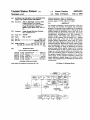
DoCuIvIENT SELECTION
/I//08
READ REFERENCE NUMBERS
"(/09
DE-COMPRESS GRAPHICS
J‘HO
DISPLAY TExT, FIRST GRAPHIC,
REFERENCE NUMBERS,
1/22
SCRoLL CoNTRoL BOXES
1729
WAIT FQR INTERRuPT
\
f/25
DECODE ENTRY
i
ZOOM AND
CENTER
/5/5
l
I
:
i
SCROLL
TEXT
l
I
~
-
'
SCRoLL
GRAPHICS
/40
62
’
\
i
l
_
DISPLAY OTHER
GRAPHIC 0R TABLE
J
|
I- ———— ——1
I
OTHER KEY
54/ PAD ENTRIES
FIG: 7
I
I
US. Patent
3/
32
i’
i
30-11
30-14
Feb. 6, 1990
33
7
30-15
Sheet 8 of 14
34 '
//8
//9
4,899,292
/20
/2/
L
‘v
4
Q
,
30-16
Ln Dn
Ln Up
Pg Dn
Pg Up
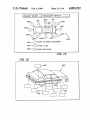
LOWER BALL JOINT
Removal
A. Raise car on hoist and remove
wheel and tire assembly.
8. Loosen but do not remove. stud
nut (nut should be loosened not
more than one turn).
c, install tool .1023742 between
studs and turn threaded end of
tool until stud is free of steer
ing knuckle.
it a hoist is not used‘for this
operation, the lower suspension
arm must be supported to prevent
the chassis spring from forcing
the-suspension arm downward.
D. Remove lower stud nut.
E_ Pull outward on bottom of tire
and at same time pushwheei and
I
/
FIG .9
27
Ln On
Ln Up
Pg Dn
Pg Up
tool until stud is tree of steer
ing knuckle.
it a hoist is not used for this
operation. the lower suspension
arm must be supported to prevent
the chassis spring from forcing
the suspension arm downward.
F_ Remove lower stud nut.
(5_ Pull outward on bottom of tire
and at same time push wheel and
tire assembly upward to tree
knuckle from spherical Joint stud
(observe FIGURE 30-11).
H, Lift up on upper suspension arm,
with knuckle and hub assernbl
attached. and place a block 0
wood between frame and upper arm.
FIGURE 30-14.
NOTICE: Do not pull on the brake
US. Patent
Feb. 6, 1990
4,899,292
Sheet 9 of 14
FROM STEP I25
I
//5/
DETERMINE X-Y OF TOUCH
M350
M352
MAP ON IMAGE
M354
DETERMINE NEW
PLACEMENT OF IMAGE
TRANSMIT LEFT UPPER
CORNER TO PROCESSOR 102
4/355
DETERMINE ADDRESSES OF
4/360
NEW CENTERED IMAGE
TRANSMIT ADDRESSES TO
MEMORY CONTROL I I6
4/362
SWITCH BUS INTERFACE
#364
INTO 32 BIT MODE
I
TO STEP 123
. F/G. ll
US. Patent
Feb. 6, 1990
Sheet 10 of 14
| MENU OF FUNCTIoNS
k’ 400
I
FMENU OF CDNTINENTSJI
JR, 402
WENU OF MANUFACTURERS
‘I’
$404
‘I
| MENU OF MoDELS
‘
4,899,292
J~406
II
[MENU OF BODY STYLES
p407
I
I
|~408
J’
J'P4Q9
[MENU OF ENGINE SIZES .
WZCESS DOCUMENT
WEAD REFERENCE NUMBERS OF GRAPHICS
IP4/0
I
lDECoMPRESS GRAPHICS
k4”
I
l ADMINISTRATIVE WORKSHEET
-
Jv4/2
‘l!
| PoINT OF IMPACT IMAGE
k4/4
I,
WAIT FOR INTERRUPT
[14/5
I
,l DECoDE INTERRUPT
{~4/6
l DISPLAY MENU 408
I46
I
l DISPLAY SELECTED IMAGE
JMW
\l
W
4/9)
{WAIT FOR INTERRUPT
F
j-4/a
II
DECoDE INTERRUPT
424
SCRDLL /
|
f422
4262
429/
zooM-IN AND
SELECT
oTHER
CENTER
PARTS
ENTRY
430)
LEFT, RIGHT
BOTH
FIG‘. 12/0)
I
TO STEP 432
US. Patent
Feb. 6, 1990
Sheet 11 of 14
4,899,292
FROM STEP 430
DISPLAY REPAIR,
REPLACE, REFINISH
1’ 432
DISPLAY LABOR
WORKSHEET
""434
ESTIMATE COST
q,436
OF REPAIR
END
ESTIMAIIE
F/G. lZ/b/
SELECT SECTION AND PRESS NEXT SCREEN
VEH IIIESC OPTIONS
ID
RATES
ADMIN
REMARKS IMPACT
/
F ONT EXTERIOR/INTERIOR
SHEET METAL
/
PAINT AND CLIPS
I STRIPES AND MOULDINGS
FRONT DOQRS AND LOCKS
-
REAR EXTERIOR / INTERIOR
SHEET METAL
ENGINE/MECHANICALS
FRONT AND REAR
SUSPENSIONS
WHEELS
INTERIOR COMPONENTS
MANUAL D/E
REVIEW
SAVE
FIG. 13
PHONE
US. Patent
Feb. 6,1990
PRIMARY IMPACT___
45/
Sheet 12 of 14
4,899,292
SECONDARY IMPACTS .__ .____
462
a
46/
452
460
453
459
(\
\
454
23/458 \\
45
454 A/@ POINT OF IMPACT UNKNOWN
' 465/»{3 TOTAL LOSS
4'56 "TO NON-COLLISION
448
US. Patent
Feb. 6, 1990
Sheet 13 0f 14
FsHoP NAME: ACE REPAIR v(:0.
W502
\OWNER.. J. JONES
[/1/ 503
REYwoRDs: W395;
_
6
5?‘;
I‘
I
/
4,899,292
J
501/
I‘!
50
500
12/‘;
A
B
c
N /O
P
_
_
j
j
FIG I6
/30
-
_
M
j
2
23/
_
524
5/0
5//
520
I14
BUFFER
EN
l:2
BUFFER
EN
lzl
BUFFER
FIG. 16’
US. Patent
Feb. 6, 1990
Sheet 14 of 14
IGXE JOmPZU
0_23m
_
QM.
_
_
_
_
_
_
_
_
_
_
MR,
J;
1
x...»
son
1
0
.
2
4
{8r{:L
7.
I
ms?“ FE S
4,899,292
1
4,899,292
2
In the automotive repair industry, service manuals
have been used to instruct a mechanic how to perform
a vrepair. However, the manuals are cumbersome to use
SYSTEM FOR STORING AND RETRIEVING TEXT
AND ASSOCIATED GRAPHICS
5
BACKGROUND OF THE INVENTION
The invention relates generally to computerized sys—
tems for storing and retrieving document text, work
sheets and associated graphics. The invention relates
more particularly to such systems which automatically
index a variety of graphics relating to a document or
text, allows an operator to conveniently and rapidly
select the graphics for display, rapidly displays the se
lected graphics, and allows the operator to rapidly and
conveniently select portions of the displayed graphics
to be enlarged and centered. The invention also relates
to such systems which estimate the cost of repairs and
display repair procedures.
Various types of systems for storing and retrieving
document text, worksheets and associated data and
graphics were previously known. For example, text,
menus and graphics have been stored in computer mem
ory and displayed in separate windows on a screen.
Controls have also been provided to scroll the windows
up, down, left and right and thereby, display different
especially in a shop environment because the mechanic
may need to search throughout the manual for informa
tion and graphics helpful to perform the necessary re
pair. Also, because of size constraints, manuals do not
include satisfactory enlargements of every image.
Heretofore, manuals have also been relied upon to
estimate the cost of repairs. An estimator views the
damaged vehicle, and determines either through obser
vation or a parts manual, the parts which are damaged.
Then, the operator estimates the cost of repair by look
ing-up in a manual the cost for each of the damaged
parts and the speci?ed time for repair. This procedure
has also proven cumbersome because more than one
manual may be required to make the estimation, and
after the initial write-up, the information may have to be
transcribed into another form. Also, the operator may
not notice every damaged part.
Automatic Data Processing, Inc. (“ADP”) has previ
ously sold a hard copy insurance estimation system. To
utilize the system, a user identi?es the model of a dam
book and reference numbers indicating the location of
associated graphics are stored together in memory.
When combined, the graphics are displayed integral
aged vehicle and then, locates in a tile cabinet a hard
copy multi-worksheet form corresponding to the
model. The worksheet includes several different views
of the model, part numbers, and lines leading from the
part numbers to the corresponding parts; The multi
worksheet also includes work space for entry of admin
istrative information. The user circles the numbers of
the damaged parts and then, a computer operator elec
with the text, that is, portions of pages of the text are
devoid of text and ?lled instead with graphics.
puter which estimates the cost of repair. The identi?ca
portions of the text, menu and graphics.
’
Book information has also been stored in computer
memory to facilitate layout of the book. Text of the
Previously known systems are also capable of enlarg
ing graphics. In one such system, a non-enlarged
graphic image is displayed, and a relatively small selec
tion box is superimposed thereon. By means of left,
right, up and down control keys, an operator can move
the box over any portion of the image. Then, by press
ing another control key, the portion of the image under
the box is centered on the screen and the image is en
larged.
In another previously known system, a mouse or
tronically transmits the part numbers to a central com
tion of the damaged parts, the storage of all the forms,
and the requirement for entry of the part numbers into
electronic form for transmission to the central computer
has proven cumbersome and prone to error.
The ADP system also includes on the multi-work
sheet, a portion similar in appearance to FIG. 14 by
40 which the user circles a code number indicating the
point of impact. The computer operator also transmits
the code number to the central computer for statistical
purposes only.
cursor is superimposed on a graphic image and moved
A general object of the present invention is to pro
to a desired location by an omnidirectional control. 45 vide a convenient, effective, electronic service manual,
Then, by pressing a control key, the portion of the
image under the mouse or cursor is centered on the
insurance estimating system or other such system.
Another general object of the present invention is to
provide a system for storing and retrieving document
screen and the image is enlarged.
Despite the advantages of centering and enlarging the ‘ text, worksheets and associated data and graphics,
graphics provided by these two previously known sys
which system automatically indexes a variety of graph
tems, it is cumbersome to make the selection by either
ics relating to a document and permits convenient and
rapid selection and display of the associated graphics.
the control keys or omnidirectional control.
The foregoing graphics have been stored electroni
A more speci?c object of the present invention is to
provide a system of the foregoing type which does not
cally in computer memory either in compressed or
non-compressed form. In non-compressed form, data 55 require a large memory for storage of the graphic im
ages in relation to the number of images which are
individually de?ning each pixel of the graphic image is
stored. While this technique allows rapid display of the
stored.
Another general object of the present invention is to
graphics, it requires a relatively large memory to store
provide systems of the foregoing type in which graphic
the data because each image has thousands of pixels and
images displayed on a screen can be more conveniently
typically, there are many graphic images required for
enlarged and centered about a desired point than in the
each system. A variety of techniques such as run-length
prior art systems.
encoding were previously known to compress video
data so that a relatively small amount of data need be
stored to represent each graphic image. However,
SUMMARY OF THE INVENTION '
when an operator selects a particular graphic image for 65 The present invention resides in apparatus and pro
cesses for storing and displaying documents and associ
viewing, the computer requires a perceivable time to
ated graphic images in insurance estimation, service
decompress the data for display, and this is undesirable
manual and other systems.
in some applications.
3
4,899,292
According to one feature of the invention, the system
stores a multiplicity of documents in digital form and a
4
multiplicity of graphic images in compressed, digital
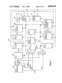
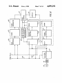
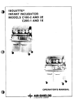
FIG. 6 is a schematic block diagram of some of the
components of FIG. 4 and shows the interconnections
between the components in more detail as well as addi
form. A ?rst group of the graphic images are associated
tional related components.
with a ?rst one of the documents. By selecting the ?rst
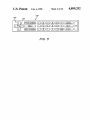
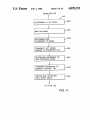
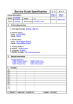
FIG. 7 is a flow chart illustrating the operation of a
document, the system automatically decompresses the
?rst plurality of graphic images. The system then dis
main microprocessor within the system of FIG. 1,
which microprocessor has been programmed to imple
plays at least a portion of the selected ?rst document on
a display screen along with a ?rst one of the decom
pressed graphic images. Subsequently, upon user com
mand, the system displays a second one of the decom
ment a service manual application.
tween the components in more detail as well as related
pressed documents. Because the second graphic image
components.
FIG. 8 is a schematic block diagram of other compo
nents of FIG. 4, and shows the interconnections be
was decompressed when the document was selected,
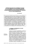
FIG. 9 is a plan view of a screen of the system of
FIG. 1 displaying a portion of document text and asso
graphic image.
15 ciated graphics for a service manual application.
The document includes reference numerals imbedded
FIG. 10 is a plan view of the screen of FIG. 9 with
there was virtually no delay in displaying the second
therein which identify the associated graphic images so
the document text scrolled downardly and the graphic
image enlarged and centered about a new point.
that when the document is selected, the system can
determine which graphic images should be decom
pressed.
FIG. 11 is a flow chart illustrating in more detail a
20
touch, centering and enlarging step illustrated generally
According to one feature of the present invention, the
second graphic image is selected by means of a touch
screen overlaying the video display so that the second
selection and display are made easily and rapidly.
in FIG. 7.
near a point on the screen which is touched.
ance estimation program of FIG. 12.
In the insurance estimation system, the system dis
plays a graphic image of a vehicle or other object. By
means of a touch screen, damaged parts are identi?ed.
FIG. 15 is a graphic image identi?ed with the aid of
the menu of FIG. 13 and/or the graphic image of FIG.
FIGS. 12(0) and (b) form a ?ow chart illustrating the
operation of the system of FIG. 1 when programmed to
implement an insurance estimation function.
In the service manual system, the document com 25
FIG. 13 is a menu displayed by the system pro
prises text describing steps for repairing a vehicle and
grammed according to the ?ow chart of FIG. 12 which
the graphic images illustrate portions of the vehicle
aids in identifying a subsequent graphic image for dis
under repair corresponding to the text.
play.
According to another feature of the invention, the
FIG. 14 is a plan view of a graphic image displayed
graphic image can be enlarged and centered about or
by the system of FIG. 1 in accordance with the insur
A local or remote processor determines the cost of 35
correcting the damage of the identi?ed parts.
14 and used to specify damaged parts.
FIG. 16 is a worksheet displayed by the system pro
grammed according to FIG. 12 and illustrates the entry
of alphabetic information.
According to one feature of the insurance estimation
system, a ?rst one of the graphic images is a view of the
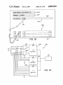
FIG. 17 is a block diagram of electronic components
vehicle as a while, and the control means is responsive
within a bus interface, memory controller and memory
to a touch on the touch screen for displaying a second, 40 of FIG. 8.
more detailed graphic image corresponding to a dam
FIG. 18 is a partial, schematic diagram of logic cir
cuitry within the interface of FIG. 17.
aged region indicated by the touch. Alternately or in
conjunction with the ?rst graphic image, the system
may display a menu for identifying a variety of graphic
images corresponding to the damage area.
45
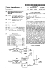
BRIEF DESCRIPTION OF THE FIGURES
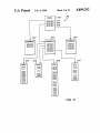
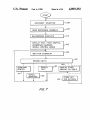
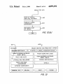
FIG. 1 is a block diagram illustrating in broken line a
system for storing and retrieving document text and
associated graphics according to the present invention.
FIG. 1 also illustrates outside of the broken line steps
for programming the system to implement a particular
process.
FIG. 2 is a schematic diagram of the layout in elec
tronic memory of document text, reference numerals 55
imbedded therein, and associated graphics, data table
and software routine addressed by the reference num
bers. The text, graphics, data table and software routine
may be stored on CD-ROM within the system of FIG.
1.
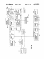
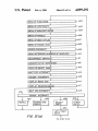
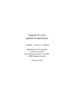
FIG. 3 is a schematic diagram of a three-tiered, hier
archical indexing or menu system to access the docu
DETAILED DESCRIPTION OF THE
PREFERRED EMBODIMENTS
Turning now to the figures in detail wherein like
reference numerals indicate like elements throughout
the several views, FIG. 1 schematically illustrates a
multidocument storage and retrieval system generally
designated 20 in accordance with the present invention.
The system 20 includes a computer terminal 22 which
includes a screen 23 for displaying text, graphics, data
and worksheets associated with each document and
stored on a CD-ROM 24. By way of example, screen 23
is a 640x400 liquid crystal display Model BF642F93
manufactured by Seiko Instruments U.S.A., Inc. This
model provides a minimum brightness of 50 cd/M2 with
a contrast of 1:10. The nominal refresh rate is 60 HZ.
FIG. 1 also illustrates the steps in programming the
system 20. In step 25, the user furnishes information
de?ning text and associated graphics and data of a par
ticular application. For example, in a service manual
application, the text includes a description of many
ment of FIG. 2 and other documents within the system
of FIG. 1.
different repair procedures. The graphics include differ
FIG. 4 is a schematic block diagram of components 65 ent views of a vehicle or other object under repair. The
of the system of FIG. 1 and their basic interconnections.
data includes tables such as parts’ lists. In an insurance
FIG. 5 is a plan view of a keypad of the system of
estimation function, the data includes the names of mod
FIG. 1.
els of vehicles or other objects under repair, parts lists
5
4,899,292
6
and costs, and the graphics include different views of
the vehicle or other object being repaired.
presents a few, for example three, broad categories of
Then, in step 27, speci?cations for the application are
developed. The speci?cations include composition re
the three possibilities by either a keyboard entry or
repair within boxes 201-203. The user can select any of
touch within the box as described in more detail below.
Each of the selections 201-203 is linked to a lower level
quirements such as pagination, layout and new or exist
ing relationships that the user wishes to establish be
tween sections of the document, menu selections,
graphic to text or data links, and other links as described
in more detail below. The information according to the
tailed information about the linked hyperpages. Menu
200 may include, for example, in selection box 202,
speci?cations is then input to another computer termi
nal 19 where it may be stored on computer tape (step
“upper ball joint”, “lower ball joint”, “front upper sus
pension arm” and “front lower suspension arm.” Each
of the selections from the lower level menu 205 is linked
26). If the information is originally in hard copy form,
menu 204-206, respectively, which provides more de
“front end”, and corresponding menu 205 may list
to a corresponding hyperpage. Hyperpages 207-210
then it may be entered into computer 19 by an associ
were listed on menu 205. For simplicity, the other hy
ated keyboard or sheet reader (not shown), and if the
information is originally stored electronically, then it 15 perpages linked to menus 204 and 206 are not illustrated
in FIG. 3.
may be transferred electrically into computer 19. In
either case, the information is stored in ASCII or such
code. Then the pages or sections of the document and
Referring again to FIG. 1, in step 44, speci?cations
Text 27 for one logical section of a document such as
are provided to de?ne the functional requirements of
the software for system 20. In step 46, an operator de
velops a main application speci?c software based on the
specifications. The software is used to retrieve and pres
ent the text, worksheets, graphics and data and perform
a description of a procedure for repairing one defective
computations according to the desired application and
part is grouped together in a single, long “hyperpage”
28, but separated from associated graphics 31-33 and
25 described in more detail below with reference to FIGS.
worksheets are composed, and index ?les and other
relationships established as illustrated in FIG. 2-(step
43).
data table 34. At locations in the text which correspond
to the associated graphics and data table 31-34, respec
tively, reference numbers 37-40, respectively, are en
commands entered into the terminal 22 by a user, and is
7 and 12. The software is stored in either of three ways,
on a ?oppy disk 48, in PROM 50 within terminal 22, or
on the CD-ROM 24 by prior entry into computer 19
with the document during step 43. If desired, the op
tered in the text stream.
A reference number 41 may also be imbedded at the 30 tional software routine 42 may also be stored on ?oppy
disc 48. By way of example, ?oppy disc 48 is a Sony
- beginning’ of hyperpage 28 to call-up a special software
subroutine 42. However, as described in more detail
below, one software routine may be provided to utilize
Model MP-F83WOOD with a 3.5" diameter and 1.44
megabyte capacity.
In step 54, the text 27, graphics 31-33, data table 34,
many hyperpages 28 of text and associated data and
graphics and referenced otherwise so that this reference 35 optional software subroutine 42 and main software pro
gram (if destined for the CD-ROM) are written from
and subroutine may. not be necessary.
the computer tape onto the CD-ROM 24. Although not
A block of information de?ning each graphic image
illustrated in FIG. 2, data de?ning optional worksheets
31-33 is compressed and stored in computer 19. Simi
generated in step 27 are also written onto the CD-ROM.
larly, a block of information de?ning data table 34 and
an optional block of information de?ning software sub 40 The basic components of computer terminal 20 are
schematically illustrated in FIG. 4. Terminal 20 in
routine 42 may also be stored in the computer 19 mem
cludes a master microprocessor 60 which implements
ory. Multiple software subroutines such as 42 may also
the main software routine stored on either CD-ROM
be provided and accessed for one procedure and, if
24, PROM 50 or ?oppy disk 48. By way of example,
desired, different hyperpages can share the same soft
ware subroutine. The reference numbers 37-41 indicate 45 microprocessor 60 is Model 80C88 manufactured by
Harris Corporation. Microprocessor 60 communicates
the present locations in computer 19 memory and the
with the remainder of the system via a bus 65 which, by
subsequent locations in CD-ROM 24 of the correspond
way of example, is Model FE2010 manufactured by
ing blocks of information de?ning the graphic images
Faraday Electronics and/or Western Digital Company.
31-33, data table 34 and optional software routine 42,
Microprocessor 60 reads the software if stored on disk
respectively. Thus, text and the associated graphics,
48 with the aid of disk drive and control 62, and if
data and optional software routine are linked to one
stored on CD-ROM 24 with the aid of CD-ROM reader
another by the reference numbers. For example, if one
63 via CD-ROM interface 67. In either case, the soft
hyperpage of text relates to a particular automobile
ware may be downloaded into dynamic random access
repair procedure, the text may be linked to graphic
memory (DRAM) 72 which by way of example has a
diagrams of the portion of the automobile having the
640K byte capacity.
part to be replaced and the surrounding parts which
A membrane keypad 74 illustrated in FIG. 5 allows a
provide access to the defective part. The data table may
user to initiate a program by suitable entry. The entry is
provide the manufacture and part number of the defec
read by microprocessor 60 with the aid of keyboard and
tive part, and the software subroutine may inform the
user that if he or she repairs or replaces a part such as a 60 touch screen interface 76 via bus 65 which interface
lower ball joint, then he or she must also perform a
related service such as a front wheel alignment.
In step 43 of FIG. 1, index ?les are also generated to
~ provide menus which locate and access desired hyperp
encodes the keyboard entry. A transparent touch screen
70, illustrated in FIG. 1, overlays the display screen 23.
By way of example, the touch screen is a resistive touch
screen manufactured‘ by Microtouch Systems, Inc. of
ages. There may be thousands of text hyperpages and 65 Massachusetts, U.S.A., and is capable of resolving the
640x400 display pixels. Referring again to FIG. 4, the
associated graphics and data tables stored on CD-ROM
location of the area touched is decoded as follows. A
24, and system 20 provides a hierarchical'indexing sys
voltage is applied to one side edge of the touch screen
tem 198 illustrated by FIG. 3. A top level menu 200
7
4,899,292
and the opposite side edge is grounded. Wand or stylus
130 is connected to the input of an A/D converter (not
shown). The touch screen is resistive so that the voltage
at the point of touch corresponds to the location be
tween the aforesaid side edges. Next, the voltage is
applied to one of the other perpendicular side edges and
the opposite side edge is grounded to determine the
location between these two side edges. Software previ
ously loaded into PROM 50 from either CD-ROM 24
or floppy disk 48 controls this decoding operation. The
8
After selecting from this menu by touch-screen 70,
either menu 204, 205 or 206 is displayed. After selecting
from one of the latter menus, a document such as the
one including hyperpage 28, graphics 31-33 and data
table 34 de?ning the selected repair procedure is identi
?ed (step 108).
In addition to utilizing the menus 200 and 204-206
illustrated in FIG. 3, microprocessor 60 is optionally
programmed to read in step 108 key words to locate one
or more hyperpages which contain some or all of the
decoded information is transmitted to microprocessor
60 via bus 65. Thus, the user can make selections and
key words. The key words may be input through a
keyboard 500 which is displayed on screen 23 as illus
commands relating to text, worksheets, graphics and
trated in FIG. 16. To display keyboard 500, data de?n
data displayed on screen 23 by either keypad 74 or
ing keyboard 500 and worksheet 501 was downloaded
touch screen 70.
15 from CD-ROM 24 into DRAM 22 at the time that the
A static random access memory (SRAM) 78 stores
document was identified. To utilize the keyboard 500,
calibration constants representing the alignment of the
?rst one of selection boxes 502, 503 or 504 is selected by
touch screen relative to the display screen and other
a touch with stylus or wand 130. To permit keyboard to
information described below.
?t on the screen, the normal distance between adjacent
An electronic clock and calendar module 80 is also
rows of lettering may be reduced by eliminating one or
provided to assist system 20 in generating reports. A
more of the intervening blank raster lines. Microproces
parallel data port 81 provides communication with a
sor 60 reads the location of the touch from interface 76,
printer and serial data ports 82 provide communication
and based on decoding software stored within PROM
with a central computer 437 via a modem 89.
50 correlates the touch with the category within the box
Communication channels between the foregoing ele 25 in order to read and display the information in each
ments of system 20 are illustrated in more detail in FIG.
category. For example, as illustrated by broken-line in
6, along with additional related components. To trans
FIG. 16, the user touched box 504 after completing
mit data, microprocessor 60 transmits via lines 300 an
boxes 502 and 503. After touching box 504, micro
address of the destination component to bus controller
processor 60 is programmed to display the subsequent
65 and latch 302. Microprocessor 60 also transmits the 30 letters in box 504 and to treat the letters as one or more
data via lines 304 to buffer 306, and a write command
key words. Then the user successively touched letters
via line 310 to bus 65. An address decoder 312 transmits
“C”, “A”, “R” and “B” to begin spelling the ?rst key
corresponding enable signals to the destination compo
word “carburetor.” The user may then enter the re
nent via lines 314. Then the destination component
mainder of the key word “carburetor”, and other key
reads the address at which the data should be stored
from latch 302 via bus or lines 318 and then reads the
data from buffer 306 via bus or lines 320.
and “poor acceleration” in order to access a procedure
To read data, microprocessor 60 transmits the ad
words such as, “Cadillac”, “V-8/450HP”, “fast idle”
for making the necessary repair. Thus, this indexing
scheme diagnoses the problem as well as accesses tex
dress of the source component to bus controller 65 and
tual and graphic information necessary to make the
latch 302, and a read command on line 310 to bus con 40 repair. As further illustrated in FIG. 16, keyboard 500
troller 65. In response, address decoder 312 transmits
was previously used to enter the name of the repair shop
corresponding enable signals to the source component
by touch of box 502 followed by touch of the letter
via lines 314. Next, the source component reads the
boxes on keyboard 500 which spell the repair shop
address at which the data should be read from latch 302
“ACE REPAIR CO.”. Similarly, the name of the
via lines 318, and then transmits the data into buffer 306 45 owner of the vehicle “I. JONES” was also entered by
via lines 320. Microprocessor 60 reads the data from
touch of box 503 and then boxes on keypad 500.
buffer 306.
.
Referring to FIGS. 7 and 8, after the document selec
FIG. 4 also illustrates an image decompression board
tion, microprocessor 60 transmits a sector address to
95 comprising a dedicated processor 96 and an associ
CD-ROM interface 67 via bus 320 to locate the selected
ated DRAM 97 providing work space for the decom
document, and afterwards reads all the reference num
pression process. By way of example, board 95 is a
bers within the document identifying all the graphic
Model TMS-340l0 manufactured by Texas Instruments
images within the selected document (step 109). Then
of USA. As described in more detail below, with refer
CD~ROM reader 63 accesses the graphic information
ence to FIG. 7, decompression board 95 decompresses
under the control of processor 60, which processor then
the graphic image data stored on CD-ROM 24 or 55 extracts header information de?ning the size of the
?oppy disk 48, and transmits the decompressed data to
image and each region on the screen 23 which forms a
a DRAM 99 for storage within a graphics controller
touch pad as described in more detail below. The
board 100. In the decompressed form, data defining
header information is stored in DRAM 72. Then, in step
each pixel for the screen provides a one-to-one mapping
110, decompression processor 96 reads the compressed
and capability for instantaneous display. A graphics 60 graphic data of the selected document from CD-ROM
controller processor 102 on board 100 controls the
20 via interface 67 and decompresses the data with the
transfer of the decompressed graphics data to screen 23.
aid of workspace DRAM 97 and DRAM controller
FIG. 7 is a flow chart illustrating the utilization of
114. Then, processor 96 transmits the decompressed
system 20 is an electronic service manual application.
graphic image data to graphic control processor 102 for
However, it should be understood that system 20 can be 65 storage in DRAM 99 with the aid of memory control
programmed to implement a wide variety of processes.
116. Memory control presents the addresses specified
Initially, a user may request via keypad 74 the menu 200
by microprocessor 102 to DRAM 99 in two parts in two
different cycles. One part specifies a column and the
of repair procedures contained within CDLROM 24.
4,899,292
10
other part specifies a row. Data is read from DRAM 99
addresses of the graphic image data to address genera
similarly in two cycles (DRAM control 114 operates
similarly upon DRAM 97). By way of example, CCITT
tor 504 within memory control 116, a write command to
Group IV run length encoding was used to compress
the data originally written into CD-ROM 24 and pro
cessor 96 implements corresponding run length decod
ing in the decompression process. Thus, all the graphic
image data in decompressed form associated with the
write generator 506, and an output enable signal to
generator 508. Generator 508 enables the correspond
ing memory bank within DRAM 99. Thus, the data is
written into DRAM 99 via data buffer 502. In the 1:4
zoom-out mode of step 122, all of the memory banks
output their data simultaneously to logic 510 which
selected document is available from DRAM 99 for
performs the OR function on the ?rst and third pixels of
instantaneous display on screen 23. This satis?es one
each group of four and the elimination of the second
and fourth pixels to yield a total of sixteen pixels of data
object of the invention in that the size requirement for
CD-ROM 24 is minimized because it stores graphic
image data of hundreds or thousands of graphic images
in compressed form, and at the time a procedure is
which are transmitted simultaneously to pixel control
127. Logic 510 is illustrated in more detail in FIG. 18 in
fragmentary form. Data is supplied on sixteen lines 511
identi?ed, only the graphic images associated with the
to logic 510 although, for simplicity, only eight of the
selected procedure are decompressed and stored in
DRAM 99 for instantaneous display.
Next in step 122, microprocessor 60 causes a ?rst
ory banks 531-533 also supply sixteen pixels of data on
portion of the document text 27, the ?rst referenced
graphic image 31, reference numbers 31-34, and text
scrolling control symbols 118-121 to be displayed on
lines 511 are shown. In addition, each of the other mem
sixteen lines 513, 515 and 517, respectively, although all
lines are not shown. The ?rst and third pixel of each
20 group of four are supplied to an OR gate 520, and the
outputs of the OR gates 520 are supplied to 1:4 buffer
524. Similarly, the outputs of the OR gates associated
with the data input via lines 513, 515 and 517 are sup
processor 60 transmits the address of the text to CD
plied to other OR gates 520 which output to other buff
ROM reader 63 via bus 320 and interface 67. Then, a
portion of the text is read into SRAM 123 via interface 25 ers 524 (not shown). In the step 122, the 1:4 buffers 524
are enabled so that in total sixteen pixels of data are
67 and text bus interface 124. The processor 102 then
supplied simultaneously to pixel control 127, and the 1:4
determines the amount of text which will fit on screen
screen 23 as illustrated in FIG. 9. To do this, micro
23 at one time, and memory controller 116 addresses the
text in SRAM 123 via lines 125. The addressed text is
zoom-out mode is implemented.
transformed into actual alpha numeric characters by a
character generator 126. A pixel controller 127 com
bines the text character data with decompressed
graphic data received from DRAM 99. In the illustrated
tion of screen 23 and includes a title “Lower Ball Joint”,
subtitle “Removal” and a body describing a procedure
embodiment of system 20, the alphanumeric informa
‘
The text portion 27 is displayed in a righthand por
for removing a lower ball joint. The remaining portion
of the procedure is not displayed at this time because it
cannot fit on the screen. The graphic image 31 is dis
tion within each of the images such as label 129 is stored 35 played separate from the text to allow independent
enlarging and scrolling of the graphic image and inde
and retrieved as graphic information. However, the
pendent scrolling of the text.
data table 34 in addition to text 127 is stored and re
In addition to displaying the text and graphics on
trieved as text.
screen 23, microprocessor 60 also causes the display of
Interface 128 selects sixteen pixels of data from either
text line-down, line-up, page-down and page-up control
16, 32 or 64 pixels of data stored in DRAM 99 in accor
boxes or touch pads 118-121 respectively by addressing
dance with a zoom level of the image. The image pres
the coresponding data from DRAM 72, and writing the
ented in step 122 ?lls window 61 of screen 61, and ordi
data into static random access memory (SRAM) 123 via
narily DRAM 99 contains four times the detail and data
bus interface 124. These control boxes control the
necessary to fill the window at the zoom level indicated
in step 122. Pixel controller 127 is designed to combine 45 scrolling of the text either line-by-line or page-by-page.
To institute such control, the user simply touches the
sixteen pixels of graphic data with the text from charac
appropriate control box with the wand 130.
ter generator 126, so that bus interface 128 under the
FIG. 9 also illustrates that reference numbers 3l-34
control of processor 102 presents'the sixteen pixels of
are displayed above graphic image 31 in boxes or touch
graphic data simultaneously to control 127. However,
as described below with reference to FIG. 17, ordinar
ily in step 122, interface 128 extracts sixteen pixels of
data from DRAM 99 by ignoring the second and fourth
pixel in both the X and Y directions and performing an
“OR” function on the ?rst and third pixels of every
group of four pixels. The result is one pixel of data for
every four pixels stored in DRAM 99 but the one pixel
contains information from every other bit in the group
so it will not miss a line.
To implement step 122, microprocessor 102 transmits
pads on screen. These numbers were extracted from the
document text in CD-ROM 24.
Next, according to the flow chart of FIG. 7, micro
processor 60 waits for an interrupt indicating an entry
either through keypad 74 or touch screen 70 (step 129).
Upon receipt of the interrupt, microprocessor 60 reads
interface 76 to determine the nature of the entry (step
125). If one of the text scrolling control boxes has been
touched, microprocessor 60 jumps to a scrolling sub
routine stored in DRAM 72 and scrolls the text by
image size data (1:4) to size latch 500 within interface 60 transmitting successive (or prior adjacent) addresses to
reader 63 and thereby accessing the text in CD-ROM 24
128 as illustrated in FIG. 17. Size latch 500 latches the
at successive (or prior) locations (step 132). FIG. 10
size data for subsequent control of a data buffer 502,
illustrates the text 27 after it has been scrolled several
write generator 506 and output enable generator 508
lines so that another portion is displayed. After such
within interface 128, and data multiplexor and OR func
scrolling, microprocessor 60 returns to step 129 to await
tion logic 510 within interface 128. Data buffer 502
another interrupt.
controls the routing of data from microprocessor 102 to
When the next interrupt is received, microprocessor
each of four memory banks 530-533 within DRAM 99
60'reads interface 76 to determine the corresponding
and vice versa. Next, microprocessor 102 transmits the