1
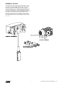
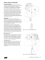
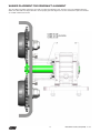
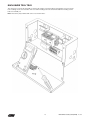
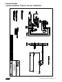
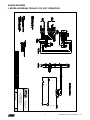
OPERATING, MAINTENANCE
& PARTS MANUAL
MOTOR-DRIVEN TROLLEY
UNIVERSAL
TROLLEY
MOTORIZED
TM
Before using the trolley, fill in the information
below. Refer to the trolley identification plate.
Model Number Serial No. Purchase Date Voltage Rated Load RATED LOADS 1 TO 3 TONNES
Follow all instructions and warnings for inspecting,
maintaining and operating this trolley.
The use of any hoist and trolley presents some risk of
personal injury or property damage. That risk is greatly
increased if proper instructions and warnings are not
followed. Before using this trolley, each operator should
become thoroughly familiar with all warnings, instructions
and recommendations in this manual.
Retain this manual for future reference and use.
Forward this manual to the trolley operator. Failure to
operate equipment as directed in manual may cause injury.
Manual Number: 33339403_150579 (REV AA) June 2015
CM HOIST PARTS AND SERVICES ARE AVAILABLE IN THE UNITED STATES AND IN CANADA
As a CM user, you are assured of reliable repair and parts services through a network of Master Parts Depots and Service Centers that
are strategically located in the United States and Canada. These facilities have been selected on the basis of their demonstrated ability to
handle all parts and repair requirements promptly and efficiently. Below is a list of the Master Parts Depots in the United States and Canada.
To quickly obtain the name of the U.S. Service Center located nearest you, call (800) 888-0985. Fax: (716) 689-5644. In the following list, the
Canadian Service Centers are indicated.
UNITED STATES MASTER PARTS DEPOT
CANADIAN SERVICE CENTERS
CALIFORNIA
NORTH CAROLINA
ALBERTA
or
OHIO
**COLUMBUS McKINNON, LTD.
10311-174th Street
Edmonton, Alberta T5S 1H1
800/263-1997
Fax 403/486-6160
OTTO SYSTEMS, INC.
12010 Bloomfield Ave.
Sante Fe Springs, CA 90670
562/462-1612 or 800/596-7392
Fax 562/462-1617
7656 Las Positas Road
Livemore, CA 94551
925/245-8800
Fax 925/245-8804
GEORGIA
TEAM SESCO
2225 Freedom Drive
Charlotte, NC 28208
704/372-4832 or 800/487-3726
Fax 704/358-1098
MAZZELLA LIFTING TECHNOLOGIES
21000 Aerospace Parkway
Cleveland, OH 44142
440/239-5700 or 800/362-4601
Fax 440/239-5707
ACE INDUSTRIES, INC.
6295 McDonough Drive
Norcross, GA 30093
770/441-0898 or 800/733-2231
Fax 800/628-3648
PENNSYLVANIA
INDIANA
RAM MOTORS & CONTROLS, INC.
5460-B Pottsville Pike
Leesport, PA 19533
610/916-8000 or 877/916-8018
Fax 610/916-7957
HORNER ELECTRIC COMPANY, INC.
1521 East Washington Street
Indianapolis, IN 46201
317/639-4261
Fax 317/639-4342
IOWA
VMI HOIST & CRANE SERVICES
901 17th Street NE
Cedar Rapids, IA 52406
319/365-4662
Fax 319/365-8075
KANSAS
INDEPENDENT ELECTRIC MACHINERY
4425 Oliver Street
Kansas City, KS 66106
913/362-1155
Fax 913/904-3330
LOUISIANA
BEERMAN PRECISION, INC.
4206 Howard Ave.
New Orleans, LA 70125
504/486-9391
Fax 504/486-7482
AMICK ASSOCIATES, INC.
11 Sycamore Street
Carnegie, PA 15106-0529
412/429-1212 or 800/445-9456
Fax 412/429-0191
TEXAS
ABEL EQUIPMENT CO., INC.
3710 Cavalier Drive
Garland, TX 75042
972/272-7706
Fax 972/272-6955
HYDRAULIC EQUIPMENT SERVICES, INC.
1021 North San Jacinto Street
Houston, TX 77002
713/228-9601
Fax 713/228-0931
WISCONSIN
TRESTER HOIST & EQUIPMENT, INC.
W136 N4863 Campbell Drive
Menomonee Falls, WI 53051
262/790-0700 or 800/234-6098
Fax 262/790-1009
BENNETT & EMMOTT, LTD.
18131 118th Avenue
Edmonton, Alberta T5S 1M8
403/454-9000
Fax 403/454-8990
BRITISH COLUMBIA
FLECK BROTHERS, LTD.
4084 McConnel Court
Burnaby, British Columbia V5A 3N7
MANITOBA
KING’S ELECTRIC MOTORS, INC.
633 Tyne Avenue
Winnipeg, Manitoba R2L 1J5
204/663-5332
Fax 204/663-4059
NOVA SCOTIA
*W & A MOIR
95 Ilsley Ave.
Burnside Park, Nova Scotia B3B 1L5
902/468-7720
Fax 902/468-3777
ONTARIO
*R & W HOIST REPAIR, LTD.
790 Redwood Square
Units 5, 6, & 7
Oakville, Ontario L6L 6N3
905/825-5500
Fax 905/825-5315
*TORONTO ELECTRIC HOIST
SALES & SERVICE
9 CoDeco Court
North York, Ontario M3A 1A1
416/386-0820
Fax 416/386-0821
*MASLACK SUPPLY, LTD.
488 Falconbridge Road
Sudbury, Ontario P3A 4S4
705/566-1270
Fax 705/566-4208
MASSACHUSETTS
ABEL DISTRIBUTORS, INC.
50 Parker Street, Unit 2
Newburyport, MA 01950
978/463-0700
Fax 978/463-5200
*COLUMBUS McKINNON, LTD.
P.O. Box 1106
10 Brook Road, North
Cobourg, Ontario K9A 4W5
905/372-0153
Fax 905/372-3078
NEW JERSEY
SHUPPER-BRICKLE EQUIPMENT CO.
2394 Route 130, Suite C
Dayton, NJ 08810
732/438-3888
Fax 732/438-3889
QUEBEC
*HERCULES SLING & CABLE
3800 TransCanada Highway
Pointe-Claire, Quebec H9R 1B1
514/428-5511514/48631-5511
Fax 514/428-5555
NEW YORK
VOLLAND ELECTRIC EQUIPMENT CO.
75 Innsbruck Drive
Buffalo, NY 14227
716/656-9900
Fax 716/656-8898/8899
*LEGER PALANS ET OUTILLAGES, INC.
7995-17th Ave.
Montreal, Quebec H1Z 3R2
514/376-3050
Fax 514/376-0657
*ARE ALSO MASTER PARTS DEPOTS
**MASTER PARTS DEPOT ONLY
i
Manual Number: 33339403_150579 (REV AA) June 2015
OPERATING AND SAFETY PROCEDURES
SAFETY PRECAUTIONS
Each Universal Motor-Driven Trolley is built in accordance with
the specifications contained herein and at the time of manufacture
complied with our interpretation of applicable sections of the
*American Society of Mechanical Engineers Code B30.11 “Monorail
Systems and Underhung Cranes,” the National Electrical Code
(ANSI/NFPA 70) and the Occupational Safety and Health Act. Since
OSHA states the National Electrical Code applies to all electrical
installations and utilization equipment, installers are required to
provide current overload protection and grounding in keeping
with the code. Check each installation for compliance with the
application, operation and maintenance sections of these articles.
Improper operation of a trolley can create a potentially
hazardous situation which, if not avoided, could result
in death or serious injury. To avoid such a potentially
hazardous situation, the operator shall follow these
operating and safety procedures.
The following are operating and safety procedures for safe
operation of the Universal Motor-Driven Trolley. Taking
precedence over any specific rules listed here, however,
is the most important rule of all, USE COMMON SENSE.
A few minutes spent reading these rules can make an
operator aware of dangerous practices to avoid and
precautions to take for his own safety and the safety of
others. Frequent examinations and periodic inspections
of the equipment as well as a conscientious observance
of safety rules may save lives as well as time and money.
After you have completely familiarized yourself with the contents of
this manual, we recommend that you carefully file it for future reference.
*Copies of this standard can be obtained from ASME Order
Department, 22 Law Drive, Box 2300, Fairfield, NJ 07007-2300, U.S.A.
1. Immediately after installation, operate trolley (according
to the Operating and Safety Procedures as follows)
with 100% load over the entire length of runway or
monorail system to be sure that all adjustments and
operations are satisfactory.
HIS SYMBOL POINTS OUT IMPORTANT SAFETY
T
INSTRUCTIONS WHICH IF NOT FOLLOWED COULD
ENDANGER THE PERSONAL SAFETY AND/OR
PROPERTY OF YOURSELF AND OTHERS. READ
AND FOLLOW ALL INSTRUCTIONS IN THIS MANUAL
AND ANY PROVIDED WITH THE EQUIPMENT BEFORE
ATTEMPTING TO OPERATE YOUR UNIVERSAL
MOTOR-DRIVEN TROLLEY.
2. Rail stops must be installed for all trolleys operating on open
end beams. These stops must be positioned such that
impact forces are absorbed by the trolley sideplates only.
3. When preparing to lift a load, be sure that the
attachments to the hook are firmly seated in hook saddle.
Avoid off-center loading of any kind, especially loading on
the point of hook.
4. When lifting, raise the load only enough to clear the floor
or support and check to be sure that the attachments to
hook and load are firmly seated. Continue lift only after
you are assured the load is free of all obstructions.
5. When applying a load, it should be directly under the
trolley. Avoid off-center loading of any kind.
6. Take up a slack load chain carefully and start lifting load
slowly to avoid shock and jerking of hoist load chain. If there
is any evidence of overloading, immediately lower the load
and remove the excess load.
7. DO NOT allow the load to swing or twist while hoisting.
8. Anticipate the stopping point and allow trolley to coast
to a smooth stop. Reversing or “plugging” to stop trolley
causes overheating of motor and swaying of load.
9. DO NOT load trolley beyond the rated capacity.
Overload can cause immediate failure of load carrying
parts or cause damage resulting in future failure at less
than rated capacity.
10.DO NOT use this or any other overhead materials
handling equipment for lifting or transporting people.
11.Stand clear of all loads and avoid moving a load over
the heads of other people. Warn people of your intention
to move a load in their area.
12.DO NOT leave the load suspended in the air unattended.
13.DO NOT wrap the load chain around the load and hook onto
itself as a choker chain. Doing this will result in the following:
a. Operation of the upper limit switch is bypassed
and the load could hit the hoist.
b. The loss of the swivel effect of the hook which
could mean twisted chain and a jammed liftwheel
c. The chain could be damaged at the hook.
14.Permit only qualified personnel to operate unit.
ii
Manual Number: 33339403_150579 (REV AA) June 2015
NOTES
iii
Manual Number: 33339403_150579 (REV AA) June 2015
FOREWORD
This manual contains important information to help you properly install, operate and maintain the Universal Motor-Driven Trolley for maximum
performance, economy and safety.
Please study its contents thoroughly before putting your trolley into operation. By practicing correct operating procedures and by carrying
out the recommended preventive maintenance suggestions, you will experience long, dependable and safe service.
After you have completely familiarized yourself with the contents of this manual, we recommend that you carefully file it for future reference.
TABLE OF CONTENTS
LIST OF TABLES
SAFETY PRECAUTIONS
Operating and Safety Procedures�������������������������������������������������������ii
Foreword�������������������������������������������������������������������������������������������� 1
GENERAL INFORMATION
Table Title Universal Motor-Driven Trolley Specifications������������������ 3
1
Page
LIST OF ILLUSTRATIONS
Layout������������������������������������������������������������������������������������������������� 2
Specifications������������������������������������������������������������������������������������� 3
Figure Table
CM Repair/Replacement Policy��������������������������������������������������������� 3
INSTALLATION
Unpacking Information����������������������������������������������������������������������� 3
Suspension Kit to Hoist���������������������������������������������������������������������� 3
Page
1
Hoist and Trolley General Arrangement���������������������������� 4
2
Hoist and Trolley General Arrangement���������������������������� 4
3
Strain Relief Details����������������������������������������������������������� 5
Hoist to Trolley������������������������������������������������������������������������������������ 3
Hoist / Trolley to Beam����������������������������������������������������������������������� 3
Electrical Installation��������������������������������������������������������������������������� 4
Cord Layout���������������������������������������������������������������������������������������� 4
Input Power Cord������������������������������������������������������������������������������� 4
Trolley Motor Card������������������������������������������������������������������������������ 4
Control Station����������������������������������������������������������������������������������� 5
Hoist Power Cord������������������������������������������������������������������������������� 5
Strain Relief Details���������������������������������������������������������������������������� 5
Hoist Control Cord����������������������������������������������������������������������������� 6
Combination Power / Control Cord���������������������������������������������������� 6
Grounding the Enclosure�������������������������������������������������������������������� 6
Three-Phase Units������������������������������������������������������������������������������ 6
OPERATING INSTRUCTIONS
General����������������������������������������������������������������������������������������������� 6
INSPECTION
Procedures����������������������������������������������������������������������������������������� 6
MAINTENANCE
General����������������������������������������������������������������������������������������������� 7
Optional Components������������������������������������������������������������������������ 7
TROUBLESHOOTING
Electrical Data������������������������������������������������������������������������������������ 8
UTM Washer & Spacer Placement����������������������������������������������� 9–10
TROLLEY WASHER SPACING
Ordering Instructions������������������������������������������������������������������������ 11
Control Station and Parts List���������������������������������������������������������� 12
Trolley Components and Parts List�������������������������������������������������� 13
Drive Assembly Components and Parts List�������������������������������14-15
Control Layout���������������������������������������������������������������������������������� 16
Enclosure Components and Parts List��������������������������������������� 17–18
Electric Hoist Suspension and Cord Kits����������������������������������������� 19
Wiring Diagrams������������������������������������������������������������������������� 20–22
1
Manual Number: 33339403_150579 (REV AA) June 2015
GENERAL LAYOUT
As received, your trolley kit will be preassembled with the control
assembly attached to the plain sideplate and the drive assembly
attached to the geared sideplate. The push button and cable
assembly and input power cord will be attached and wired to the
control enclosure. The motor cord will be attached and wired to
the motor. The suspension pins, washers and spacers will not be
assembled to either sideplate. The installer will be required to set the
trolley spacing according to the beam flange width the trolley
is to be mounted. A cord kit will be needed to wire the hoist to
the trolley. Some hoists use one combination cord for both power
and control while other hoists use two separate cords for power
and control.
CONTROL ASSEMBLY
DRIVE ASSEMBLY
SUSPENSION PINS
WITH HARDWARE
2
Manual Number: 33339403_150579 (REV AA) June 2015
GENERAL INFORMATION
INSTALLATION
SPECIFICATIONS
UNPACKING INFORMATION
The Universal Motor-Driven Trolley is designed for use with many
CMCO Electric Chain Hoists. The trolleys are available in 1t, 2t and
3t capacities. They are similar in design except the size of the load
carrying members. Available speeds are 15, 35 and 75 feet per
minute. 75 fpm is not available for 3t capacity, however.
After removing the trolley from the shipping carton, carefully
inspect the external condition of the cords, control box, gear
reducer and motor for damage that may have occurred during
shipment and handling. Check to make sure all parts (trolley
sideplate assembly with control enclosure, push button and
cable assembly, input power cord, trolley sideplate with gear
reducer and motor, motor cord, suspension pins, spacers,
washers, cotter pins and nuts) are furnished.
The trolleys have rugged steel sideplates, steel axles, steel
suspension pins, steel load bracket from which the hoist is
suspended and machined, forged steel wheels that are suitable for
operation on sloped or flat-flanged beams. Hardened trackwheel
gear teeth are driven by a right angle worm gear reducer. The worm
and gear of the gear reducer operate in an oil bath. An IP55 motor
drives the gear reducer.
INSTALLATION
The hoist and trolley are packed separately. The type of
top suspension may vary per hoist model, therefore, the
following installation steps will assume there is no top
suspension assembled to the hoist.
The control enclosure contains a reversing contactor, transformer
and terminal blocks. There are three enclosures available based on
supply voltages of 208v, 230v/460v and 575v. A four-button control
station is suspended from the control enclosure. The up and down
hoist control buttons are 2-step. Trolley control buttons are 1-step.
Suspension Kit to Hoist
Assemble the UT suspension kit to the hoist according to
the instructions furnished with the suspension kit and/or the
instructions in the manual furnished with the hoist. Make
sure the suspension kit is installed based on the application,
considering the hoist's reeving (single, double or triple) and
mounting (parallel or cross) configurations.
See Table 1 for general specifications of the trolley.
CM REPAIR/REPLACEMENT POLICY
All Columbus McKinnon (CM) Universal Motor-Driven Trolleys are
inspected and performance tested prior to shipment. If any properly
maintained trolley develops a performance problem within 1 (one)
year of shipment due to a material or workmanship defect, as
verified by CM, repair or replacement of the unit will be made to
the original purchaser without charge. This repair/replacement
policy applies only to trolleys installed, maintained and operated
as outlined in this manual and specifically excludes parts subject
to normal wear, abuse, improper installation, improper or inadequate
maintenance, hostile environmental effects and unauthorized
repairs/modifications.
Hoist to Trolley
It is recommended that the trolley be mounted to the
hoist prior to final installation onto the beam. Follow the
washer and spacer placement instructions (page 9 and
10) to properly set the trolley based on the application's
beam flange width. The suspension pins must be offset
toward the motor side for the UT1M and UT2M trolleys. It
is recommended to do the same for the UT3M, but it is not
required. Note: the motor-driven side of the trolley should be
located on the same side as the hoist's chain container.
We reserve the right to change materials or design if, in our opinion,
such changes will improve our product. Abuse, repair by an
unauthorized person or use of non-CM replacement parts voids
the guarantee and could lead to dangerous operation. For full Terms
of Sale, see Sales Order Acknowledgement. Also, refer to the back
cover for Limitations of Warranties, Remedies and Damages, and
indemnification and Safe Operation.
TABLE 1
An excessively worn beam flange may fail
and allow the trolley to fall from the beam.
Universal Motor-Driven Trolley Specifications
Code
Capacity
(Tonnes)
Power
Supply
(ALL
CODES)
Travel
Speed
(FPM)
UT1M*
1
208-3-60
15, 35, 75
UT2M*
2
UT3M*
3
230/460-3-60 15, 35, 75
575-3-60
Motor
(HP)
Flange
Width
(IN)
TO AVOID INJURY:
Periodically inspect the beam flange for wear.
Replace beam if flange is worn.
Min
Radius
Curve
(IN)
Hoist / Trolley to Beam
After setting the trolley, install the hoist/trolley assembly
onto the beam from the end. If this is not possible, loosen
the suspension pin castle nuts so the trolley wheels clear the
beam's flange. Lift the hoist/trolley assembly up and tighten
the suspension pin castle nuts. Lower the hoist/ trolley
assembly onto the beam's flange. Ensure rail stops are
in place after the installation is complete.
36
1/3
15, 35
2.3-8.6
45
55
*15 = 15fpm, 35 = 35fpm, 75 = 75fpm;
3 = 230/460V, 5 = 575V, 7 = 208V;
0 = Type 0, 1 = Type 1.
Example: UT1M3530 = UT1 base trolley, 35 fpm, 230/460V, Type 0.
Operating the trolley on a beam that has no rail
stops may allow the trolley to fall off the end of beam.
TO AVOID INJURY:
Install rail stops at each end of the beam
on which the trolley is to operate.
Rail stops must be positioned so as to not exert impact
force on the hoist frame or trolley wheels. They must contact
the ends of the trolley sideplates. The rubber bumper kit,
purchased separately, should be considered if trolley to rail
stop contact is frequent.
3
Manual Number: 33339403_150579 (REV AA) June 2015
INSTALLATION (CONTINUED)
Electrical Installation
Power to the trolley and hoist should be furnished from a
compatible source through a disconnect device. Overcurrent
protection and proper grounding means should be
accomplished in accordance with the “National Electrical
Code” and local codes if applicable. Power should be
disconnected when making or changing connections.
The input power cord and push button and cable assembly
are attached and wired to the control enclosure from the
factory. The motor cord is attached and wired to the motor
from the factory. A cord kit is required to connect the hoist
power and controls from the hoist to the control enclosure.
The cord kit will include either one combination cord or
two individual cords, depending on the hoist model. The
combination cord contains conductors for both power and
control connections. The two-cord kit includes a power cord
and a separate control cord.
Cord Layout
See Figure 1. When viewing the assembly from the
enclosure side, the input power cord is at the left end of the
enclosure. A knockout plug is located directly below the
input power cord. Knockout plugs are provided loose in the
enclosure. An additional knockout is provided on the left end
as well. The push button and cable assembly is attached to
the bottom left end of the enclosure.
See Figure 2. When viewing the assembly from the
enclosure side, the trolley motor cord is at the right end
of the enclosure. Note that the cord is routed through the
unused suspension pin holes in the sideplates so the cord
will not contact the beam. This particular hoist / trolley
example requires a combination cord, providing both power
and controls from the enclosure to the hoist. It is attached
to the right end of the enclosure. An additional knockout is
provided at the right end of the enclosure. Both ends of the
enclosure have the same number of holes and knockouts.
Figure 1. Hoist and Trolley General Arrangement
Note: UT2M***0 trolley shown.
Input Power Cord
The input power cord is attached and wired to the enclosure.
It is for use with a collector and bus system. It should be
discarded if a cable is to supply the trolley. Connections
to the trolley are shown on wiring diagrams, see pages 20,
21 and 22. The cord connector must be made tight on the
cable, and if necessary, a separate strain relief provided
to prevent any stress on the conductors.
Trolley Motor Cord
The trolley motor cord is attached and wired to the motor.
Connections within the enclosure are shown on wiring
diagrams, see pages 20, 21 and 22. The cord should
be routed from the motor junction box through unused
suspension pin holes in both sideplates to the control
enclosure. This will keep the cord from being damaged
by the beam.
Figure 2. Hoist and Trolley General Arrangement
4
Manual Number: 33339403_150579 (REV AA) June 2015
Control Station
The control station is suspended from the trolley control
enclosure by a cord that is approximately 17' long. If this is
too long for your application, the cord should be shortened
so that the control station is suspended approximately four
feet above the operating floor.
A clamp and sleeve are provided loose in the control
enclosure. Be sure to firmly squeeze the clamp sleeve
using a vise or very large pliers to secure the loop end.
Insulate the clamp using the rubber sleeve.
Slide the prepared cord through the cord connector under
the control enclosure. Using the wiring diagram supplied with
the trolley, or see pages 20, 21 and 22 within this manual,
connect the control cord conductors. Attach the strain relief
loop over the mounting screw and washer. Pull down on the
cord to seat the strain relief cord. Tighten the strain relief
mounting screw. Firmly tighten the cord connector.
Tying knots or loops to shorten the drop of the control
station will make the strain relief ineffective and the
internal conductors of the cord may break.
Hoist Power Cord
The hoist power cord, supplied within the cord kit, connects
power from the control enclosure to the hoist. The hoist end
of the cord will be configured just like a standard power cord
for a specific hoist while the enclosure end will be stripped
for inserting into the terminal blocks.
TO AVOID INJURY:
Shorten the control cord per the following instructions.
To shorten the cord, disconnect the trolley from the power
supply system and loosen the cord connector at the bottom
of the control enclosure. Remove the cover from the control
enclosure and disconnect the control cord conductors.
Loosen, but do not remove, the strain relief mounting screw.
Slightly push the cord inside the enclosure and unfasten
the strain relief loop. Pull the cord out of the enclosure.
Measuring from the end of the longest conductor, cut off
the cord the distance the control is to be raised. Prepare
the cable as shown below (Fig 3).
STRAIN RELIEF DETAILS
Color
Lead Length
Strip Length
Label
Condition
Location
Brown
12
Yellow
12
.35
UP
Solder Dip
3
.35
DN
Solder Dip
2
Blue
12
.35
HX1
Solder Dip
4
White
12
.35
FA
Solder Dip
1
Purple
12
.35
TL
Solder Dip
REV CONT (L)
Orange
12
.35
TR
Solder Dip
REV CONT (R)
Red
12
.35
X1
Solder Dip
5
Black
SEE STRAIN RELIEF DETAILS
–
Figure 3. Strain relief details.
5
Manual Number: 33339403_150579 (REV AA) June 2015
INSTALLATION (CONTINUED)
OPERATING INSTRUCTIONS
Hoist Control Cord
The hoist control cord, supplied within the cord kit, connects
the controls from the control enclosure to the hoist. The hoist
end of the cord will be configured just like a standard control
cord for a specific hoist while the enclosure end will be
stripped for inserting into the terminal blocks.
After the trolley and hook travel directions are correct,
lubricate the geared wheel and driveshaft gear mesh
with lubricant provided. Operate the trolley (according
to the operating and safety procedures see page ii) with
a capacity load over the entire length of he runway or
monorail system to be sure that all adjustments and
operations are satisfactory.
Combination Power / Control Cord
The combination cord is the cord kit. It connects both
the power and controls from the control enclosure to the
hoist. The hoist end of the cord will be configured just like
a standard combination cord for a specific hoist while
the enclosure end will be stripped for inserting into the
terminal blocks.
INSPECTION
To maintain continuous and satisfactory operation, a regular
periodic inspection procedure must be initiated so that worn
or damaged parts can be replaced before they become
unsafe. The frequency of inspection must be determined
by the individual application.
Grounding The Enclosure
The enclosure frame has one ground wire attached to a
green ground screw. The input power cord, motor cord, hoist
power cord and the reversing contactor will be connected
to the one ground wire using a wire cap. The wire cap is
installed from the factory less the hoist power cord ground.
The following list gives an inspection procedure for normal
usage under normal conditions. When the unit is subjected
to heavy usage or dusty, gritty, moist or other adverse
atmospheric conditions, shorter time periods must be
assigned. Inspection must be made of all parts for unusual
wear, corrosion or damage in addition to those specifically
mentioned in the list below.
TEST AND ADJUSTMENTS
FOR 3 PHASE MODELS
It is suggested that the unit be inspected monthly for wear
damage and corrosion effects to all parts with particular
attention to the following:
1. Tightness of all fasteners including trackwheel stud nuts
and suspension pin nuts.
Three phase hoists must be properly phased each time
they are installed or moved to a new power source.
Unless this is done, serious damage to the hoist can
occur with resulting hazard to the operator and load.
2. Contactor and control station for burnt or pitted contacts
and loose or corroded terminals.
3. Cables and leads for broken wires, loose or corroded
terminals, also damaged insulation.
1. To properly phase hoists follow these steps.
a. Operate "UP" button briefly to determine direction
of load hook travel.
4. Terminal blocks for loose or corroded connections.
5. Trackwheels for wear of tread and flange and for
bearing wear as indicated by excessive looseness
of wheel on stud.
b. If load hook raises when "UP" button is pressed,
phase is correct and hoist may be operated.
c. If load hook lowers, hoist is "Reverse Phased" and
must be corrected by interchanging any two leads
at power source connection. Do not change internal
wiring of hoist or trolley.
6. Trackwheel gear and pinion for wear.
7. Check suspension lug, suspension adapter and
suspension shear pin for excess wear by manipulating
hoist and visually inspecting suspension parts.
2. Check hoist upper and lower limit stop operation
to determine if limit stop functions properly in both
directions. Refer to hoist "Operation and Service Manual"
under "Testing Hoist" for method to be followed.
8. Collector or power supply system for damage,
wear corrosion and proper operation.
3. Position hoist/trolley combination on I-beam so that
enough clear track is available to allow travel of trolley
in two directions to permit checking "RIGHT" and
"LEFT" traverse operation.
Note:
Three Phase Motors: If it is desired to reverse the direction
of trolley travel in relation to the push button markings,
turn POWER OFF and interchange any two leads at trolley
motor cord / reversing contactor connection.
6
Manual Number: 33339403_150579 (REV AA) June 2015
MAINTENANCE
Lubrication requirements:
a. Wheel bearings are permanently lubricated
and require no additional lubricant.
b. Drive wheel gears are to be lubricated with an open
type gear grease which is heavy, plastic, extreme
pressure and tacky; such as MOBILTAC 275 NC
or equal.
c. The right angle worm gear reducer oil is a synthetic
lubricant with excellent wear protection capability
and long life. This oil does not require changing.
When replacing oil due to repairs, use MOBIL SHC
634 or equal.
The lubricants used in and recommended for the Universal
Motor-Driven Trolley may contain hazardous materials that
mandate specific handling and disposal procedures
TO AVOID CONTACT AND CONTAMINATION:
Handle and dispose of lubricants only as directed in
applicable material safety data sheets and in accordance
with applicable local, state and federal regulations.
IMPORTANT: Refer to manual packed with the hoist
for the inspection and maintenance of the hoist.
OPTIONAL COMPONENTS
Two kits are available:
1. Rubber Bumper
2. Tow Arm.
Rubber bumper kit:
Part number 33337905. Includes four bumpers with
required mounting hardware.
Tow arm kit:
Part number 11843111 for UT1M and UT2M; Part number
33336311 for UT3M. Includes tow arm bracket, tow arm
and required mounting hardware. (See installation
instructions 33339402)
Hanger plates are available for hook-mount installation.
The hanger plate is based on the model of trolley.
UT1M – use hanger plate 00550051
UT2M – use hanger plate 00550059
UT3M – use hanger plate 00550073
Inside the control enclosure, additional components may
be added to the unused sections of Din rail. For example,
a speed relay may be added beside the reversing contactor.
The two shorter Din rail sections may be used to mount taller
components such as a phase monitor or main line contactor.
Working in or near exposed energized electrical
equipment presents the danger of electric shock.
TO AVOID INJURY:
Disconnect power and lockout/tagout disconnecting means
before removing cover or servicing this equipment.
7
Manual Number: 33339403_150579 (REV AA) June 2015
TROUBLESHOOTING
TROUBLE
1. Trolley does not operate
in either direction.
PROBABLE CASE
REMEDY
A. No voltage at trolley
A. Main line or branch circuit switch open; branch line fuse blown
or circuit breaker tripped. Close, replace or reset. Check for
grounded or open connection in supply lines or current collectors.
B. Phase failure (single-phasing)
B. Open circuit, grounded or open connection in one line of supply
system, collectors, hoist wiring, reversing contactor, motor leads
or windings. Check for electrical continuity.
C. Open control circuit
C. Open or shorted windings in transformer or reversing contactor
coil; loose connection or broken wire in circuit; mechanical
binding in contactor; control station contacts not making.
D. Wrong voltage or frequency
D. The voltage and frequency must be the same as shown on
trolley control box.
E. Low voltage
E. Voltage at the motor must be above the minimum
with the unit in operation:
Unit Rating
Minimum Voltage
208-3-60
187
230-3-60
207
460-3-60
414
575-3-60
517
F. Excessive load
F. Reduce loading to the capacity limit of trolley.
2. Trolley operates
in one direction only.
A. Open control circuit
A. See Item 1C.
3. Trolley operates sluggishly.
A. Excessive load
A. See Item 1F.
B. Low voltage
B. See Item 1E.
C. Worn or dirty rails
C. Clean rails, inspect for worn spots.
A. Excessive load
A. See Item 1F.
B. Low voltage
B. See Item 1E.
C. Extreme external heating
C. Above an ambient temperature of 104°F., the frequency of trolley
operation must be limited to avoid overheating of motor. Special
provision should be made to ventilate the space or shield the
trolley from heat radiation. Excessive inching, jogging or plugging
should be avoided since this type of operation will drastically
shorten the life of motor and contactor. See Item 1B.
4. Motor overheats.
ELECTRICAL DATA
To detect open and short circuits in electrical components, use the following procedure.
OPEN CIRCUITS in the coils of electrical components may
be detected by isolating the coil and checking for continuity
with an ohmmeter or with the component in series with
a light or bell circuit.
MOTOR CURRENT should be measured with the motor
running under full load with rated voltage applied.
CONTACTOR COIL CURRENT should be measured with
the contactor armature (contacts) closed and full voltage
on the coil.
SHORTED TURNS are indicated by a current draw
substantially above normal (connect ammeter in series
with suspected element and impose normal voltage) or D.C.
resistance substantially below normal. The current method
is recommended for coils with very low D.C. resistance.
8
Manual Number: 33339403_150579 (REV AA) June 2015
UTM WASHER & SPACER PLACEMENT
Due to the variations in beam flange widths, it is suggested
that the beam flange width be measured to determine the
exact distribution of washers and spacers. The distance
between trackwheel flanges should be 1/8 to 3/16 inch greater
than the beam flange width for straight runway beams and
3/16 to 1/4 inch greater than the beam flange width if runway
system includes sharp curves. Also, the use of other than
CM supplied washers and spacers may result in trackwheel
to beam flange variations and thus the recommendations in
the following tables will not apply.
TRACKWHEEL
FLANGE WIDTH
BEAM
FLANGE WIDTH
OFFSET SUSPENSION PINS TO MOTOR SIDE.
LONG SPACER
(LS)
SHORT SPACER
(SS)
LUG ADAPTER
SIDEPLATE
WASHER
(W)
SIDEPLATE
9
Manual Number: 33339403_150579 (REV AA) June 2015
UTM WASHER & SPACER PLACEMENT (CONTINUED)
Each washer/spacer chart shows the available beam flange width setting from minimum to maximum. To center the hoist
under the beam, use the same amount of washers and spacers between the lug adapter and sideplates. The amount of
washers and spacers on the outside of the sideplates does not have to be the same.
Note: For triple-line Manguard, omit the long spacers on each side of the suspension adapter.
UT1 MODEL
Number of Washers & Spacers
LS
W
SS
LS
LS
SS
W
LS
SS
W
0
0
0
0
0
0
0
0
0
0
0
0
0
0
0
0
0
0
0
0
0
0
0
0
0
0
0
0
0
0
0
0
0
0
0
0
0
0
0
0
0
0
0
0
0
0
0
0
0
0
0
0
0
0
0
1
2
3
4
5
6
0
1
2
3
4
5
0
1
2
3
4
5
6
0
1
2
3
4
5
6
0
0
0
0
0
0
0
1
1
1
1
1
1
0
0
0
0
0
0
0
1
1
1
1
1
1
1
1
1
1
1
1
1
1
1
1
1
1
1
1
2
2
2
2
2
2
2
2
2
2
2
2
2
2
1
1
1
1
1
1
1
1
1
1
1
1
1
2
2
2
2
2
2
2
2
2
2
2
2
2
2
0
0
0
0
0
0
0
1
1
1
1
1
1
0
0
0
0
0
0
0
1
1
1
1
1
1
1
0
1
2
3
4
5
6
0
1
2
3
4
5
0
1
2
3
4
5
6
0
1
2
3
4
5
6
2
2
2
2
2
2
2
2
2
2
2
2
2
0
0
0
0
0
0
0
0
0
0
0
0
0
0
2
2
2
2
2
2
2
0
0
0
0
0
0
2
2
2
2
2
2
2
0
0
0
0
0
0
0
13
11
9
7
5
3
1
13
11
9
7
5
3
13
11
9
7
5
3
1
13
11
9
7
5
3
1
SIDEPLATE
SS
1
1
1
1
1
1
1
1
1
1
1
1
1
1
1
1
1
1
1
1
1
1
1
1
1
1
1
LUG ADAPTER
W
2.45
2.68
2.92
3.16
3.39
3.63
3.86
4.18
4.42
4.65
4.89
5.12
5.36
5.60
5.83
6.07
6.31
6.54
6.78
7.01
7.33
7.57
7.80
8.04
8.27
8.51
8.75
SIDEPLATE
Beam Flange
Width (in.)
UT2 & UT3 MODELS
Beam Flange
Width (in.)
Number of Washers & Spacers
SS
LS
W
SS
LS
LS
SS
W
LS
SS
W
1
1
1
1
1
1
1
1
1
1
1
1
1
1
1
1
1
1
1
1
1
0
0
0
0
0
0
0
0
0
0
0
0
0
0
0
0
0
0
0
0
0
0
0
0
0
0
0
0
0
0
0
0
0
0
0
0
0
0
0
0
0
0
0
1
2
3
4
0
1
2
3
4
0
1
2
3
4
0
1
2
3
4
5
0
0
0
0
0
1
1
1
1
1
0
0
0
0
0
1
1
1
1
1
1
1
1
1
1
1
1
1
1
1
1
2
2
2
2
2
2
2
2
2
2
2
1
1
1
1
1
1
1
1
1
1
2
2
2
2
2
2
2
2
2
2
2
0
0
0
0
0
1
1
1
1
1
0
0
0
0
0
1
1
1
1
1
1
0
1
2
3
4
0
1
2
3
4
0
1
2
3
4
0
1
2
3
4
5
2
2
2
2
2
2
2
2
2
2
0
0
0
0
0
0
0
0
0
0
0
2
2
2
2
2
0
0
0
0
0
2
2
2
2
2
0
0
0
0
0
0
11
9
7
5
3
11
9
7
5
3
11
9
7
5
3
11
9
7
5
3
1
SIDEPLATE
W
LUG ADAPTER
UT3
2.46
2.78
3.09
3.41
3.72
4.04
4.35
4.67
4.98
5.30
5.61
5.93
6.24
6.56
6.87
7.19
7.50
7.82
8.13
8.45
8.76
SIDEPLATE
UT2
2.45
2.76
3.08
3.39
3.71
4.02
4.34
4.65
4.97
5.28
5.60
5.91
6.23
6.54
6.86
7.17
7.49
7.80
8.12
8.43
8.75
Example using a UT1 model:
Measure your beam flange width - 4.94". In the beam flange width column, the measured beam size is between 4.89" and 5.12".
Always use the larger beam size setting – 5.12".
The 5.12" setting requires 1-LS (long spacer), 1-SS (short spacer) and 4-W (washers) between the lug adapter and sideplates.
The total clearance distance will be 5.12" - 4.94" = 0.18". If the application requires more clearance, move to the next larger
beam size setting- 5.36".
CAUTION: The installer must confirm that the trolley will remain on straight sections of beam at increased clearance settings.
10
Manual Number: 33339403_150579 (REV AA) June 2015
REPLACEMENT PARTS
ORDERING INSTRUCTIONS
The following information must accompany all
correspondence or orders for replacement parts:
1. Serial number – located on 1.5" x 0.8" decal affixed to
control enclosure.
2. Voltage, Phase, Hertz
When ordering motor parts, give the motor nameplate data
in addition to the above.
For parts orders also specify:
1. Quantity desired.
2. Part number.
3. Part description.
Parts should be ordered from CM’s authorized Master Parts
Depots conveniently located throughout the United States
and Canada. Refer to page i of this manual to locate the
Master Parts Depot nearest you.
NOTE: When ordering replacement parts, it is
recommended that consideration be given to the need
for also ordering such items as bearings, contacts,
fasteners, etc. These items may be damaged or lost
during disassembly or just unfit for future use because
of deterioration from age or service.
Using “commercial” or other manufacturer’s parts to repair
the Universal Motor-Driven Trolley may cause load loss.
TO AVOID CONTACT AND CONTAMINATION:
Use only CM supplied replacement parts. Parts may
look alike, but CM parts are made of specific materials or
processed to achieve specific properties.
11
Manual Number: 33339403_150579 (REV AA) June 2015
CM® 4 DIRECTIONAL CONTROL STATION PARTS LIST
Item
Part Number
Description
Qty.
1
23251009
Nut, Connector
1
2
23251012
Connector
1
3
81704
Warning Tag
1
4
582220CM
PB Station
1
1–4
33337931
PB & Cable Assembly
–
Conductors and strain relief are not shown at the end
of the cable. Remove jumper between 1 and 16 inside PB
station. Remove cable clamps inside PB station. Complete
assembly (includes items 1–4) is available as
part number 33337931.
12
Manual Number: 33339403_150579 (REV AA) June 2015
UT PARTS LIST
Item
Description
1
Part Number
Qty,
Kit Contents
UT1
UT2
UT3
SIDEPLATE KIT, GEARED
11843108
23554608
33336308
1
2 - geared wheels, 1 - geared sideplate,
2 (UT1 & UT2) or 4 (UT3) - bearings, 4 - retaining rings,
2 - axles, 2 - nuts and 2 - washers
2
WHEEL ASSEMBLY, GEARED
0508211A
0508212A
0508213A
1
1 - geared wheel, 2 - retaining rings, 1 (UT1 & UT2) or
2 (UT3) - bearings, 1 - axle, 1 - washer and 1 - nut
3
SPACER KIT, LONG
11842001
11842003
11842007
1
8 - long spacers
4
SUSPENSION PIN KIT
11843101
23554601
33336301
1
2 - suspension pins
5
SPACER KIT, SHORT
11842002
11842004
11842008
1
4 - short spacers
6
WHEEL ASSEMBLY, PLAIN
0508207A
0508208A
0508209A
1
1 - plain wheel, 2 - retaining rings, 1 (UT1 & UT2) or
2 (UT3) - bearings, 1 - axle, 1 - washer and 1 - nut
7
SIDEPLATE KIT, PLAIN
11843107
23554607
33336307
1
2 - plain wheels, 1 - plain sideplate, 2 (UT1 & UT2) or
4 (UT3) - bearings, 4 - retaining rings, 2 - axles, 2 - nuts
and 2 - washers
8
NAMEPLATE KIT
11843102
23554602
33336302
1
1 - nameplate and 4 - drive screws
9
HARDWARE KIT
11843104
23554604
33336304
1
28 (UT1) or 24 (UT2 & UT3) - suspension pin washers,
4 - slotted nuts and 4 - cotter pins
1
2
3
1/16"
4
BEAM
5
6
7
Optional rubber bumper shown
Kit Number: 33337905
8
See page 19 for hoist
top suspension kit
9
9
13
Manual Number: 33339403_150579 (REV AA) June 2015
DRIVE ASSEMBLY COMPONENTS
Item
DESCRIPTION
UT1
UT2
UT3
Qty
1
Driveshaft
33337908
33337908
33337908
1
2
Washer, Flat
H4210P
H4210P
H4210P
2
3
Key
09131071
09131071
09131071
1
4
Bolt M8
33339101
33339101
33339101
4
5
Locking washer
09122016
09122016
09122016
4
6
Adapter
33337906
33337906
33337906
1
7
SHCS, M6
33339103
33339103
33339103
4
8
Gearbox
See Table
See Table
See Table
1
9
Retaining Ring
09129028
09129028
09129028
1
10
Motor
See Table
See Table
See Table
1
DESCRIPTION
SPEED 15 (fpm)
SPEED 35 (fpm)
SPEED 75 (fpm)
Qty
Gearbox
33337911
33337910
33337909
1
DESCRIPTION
VOLTAGE 208-230/460
VOLTAGE 575
Qty
Motor
33337912
33337913
1
8
10
14
Manual Number: 33339403_150579 (REV AA) June 2015
WASHER PLACEMENT FOR DRIVESHAFT ALIGNMENT
The same drive assembly components are used no matter the UTM frame size. Therefore, since the sideplate thickness
differs, the driveshaft must be positioned to ensure proper gear teeth alignment. Use the chart below to place the washers
as needed. UT2M model shown.
15
Manual Number: 33339403_150579 (REV AA) June 2015
CONTROL LAYOUT
DESCRIPTION
UT1
UT2
UT3
UT3*
Qty
1
Decal
33339104
33339105
33339106
33339107
1
2
Cover
33337915
33337915
33337915
33337915
1
3
Enclosure**
See Table
See Table
See Table
See Table
1
4
Nut, Locking, Flanged
33337920
33337920
33337920
33337920
4
5
Nut, Locking
11803002
11803002
11803002
11803002
4
6
Screw, M8
33339102
33339102
33339102
33339102
4
7
Bracket
33337917
33337918
33337919
33337919
1
DESCRIPTION
VOLTAGE 208
VOLTAGE 230/460
VOLTAGE 575
Qty
Enclosure**
33337924
33337923
33337925
1
* For 2T MAX Models
3
** Includes Cover, Enclosure, Flanged Locking Nuts, Power Supply Cord Assembly (P/N 33334928 not shown), Motor Cord Assembly (P/N 33337930 not shown), Push Button and Cable Assembly
(P/N 33337931 not shown)
16
Manual Number: 33339403_150579 (REV AA) June 2015
ENCLOSURE COMPONENTS
If additional holes are required in the ends, make sure your connectors clear the lid when the cover is installed.
Item
Part Number
Description
Qty
1
33337916
Enclosure, with Cover
1
2
909J13
End Clamp
2
3
24799
Reversing Contactor
1
4
H4158
Washer, External Locking
2
5
H2751
Screw, #8-32
2
821J431
230/460 Transformer
821J471
208 Transformer
6
1
821J451
575 Transformer
7
39452
Flange End
1
8
39451
Single Block
7
9
39460
Double Block
2
10
39450
Single Block Flange End
1
11
982718
Screw, #5-40
2
12
33337933
Ground Wire Assembly
1
Holes and Knockout in each end:
(1) 1.065 DIA hole
(1) 0.845 DIA hole
(1) 0.845 DIA knockout
Hole and Knockout in bottom:
(1) 1.065 DIA hole
(1) 1.065 DIA knockout
17
Manual Number: 33339403_150579 (REV AA) June 2015
ENCLOSURE TOOL TRAY
The enclosure cover may be mounted as shown to be used as a tool tray. When removing the cover, loosen the
four mounting screws one revolution. Lift cover until mounting holes are centered around the mounting screws.
Pull cover toward you.
Note: the tool tray may interfere with some cross-mount hoists.
18
Manual Number: 33339403_150579 (REV AA) June 2015
ELECTRIC HOIST SUSPENSION AND CORD KITS
The CM Universal Motor-Driven Trolley is designed to suspend several electric chain hoist models that are part of the
CMCO family of brands. Select the appropriate Suspension and Cord Kit for your specific hoist listed below.
REEVING
MOUNTING POSITION
TROLLEY
SUSPENSION
KIT
CORD KIT
1&2
CROSS
UT1
20655K
33337952
CM LODESTAR (CLASSIC) (V1) (Small Frame)
1
PARALLEL
UT1
2992UT
33337950
CM LODESTAR (CLASSIC) (V1) (Small Frame)
1
CROSS
UT1
2992UTC
33337950
CM LODESTAR (CLASSIC) (V1) (Small Frame)
2
CROSS OR PARALLEL
UT1
2993UT
33337950
CM LODESTAR (CLASSIC) (V2) (Large Frame)
1
CROSS OR PARALLEL
UT2
3677UT
33337951
CM LODESTAR (CLASSIC) (V2) (Large Frame)
2
CROSS OR PARALLEL
UT2
3668UT
33337951
CM LODESTAR (CLASSIC) (V2) (Large Frame)
3
CROSS OR PARALLEL
UT3
9561UT
33337951
CM LODESTAR (NH) (V1) (Small Frame)
1
PARALLEL
UT1
2992NHUT
33337950
CM LODESTAR (NH) (V1) (Small Frame)
1
CROSS
UT1
2992NHUTC
33337950
CM LODESTAR (NH) (V1) (Small Frame)
2
CROSS OR PARALLEL
UT1
2993NHUT
33337950
CM LODESTAR (NH) (V2) (Large Frame)
1
CROSS OR PARALLEL
UT2
3677NHUT
33337951
CM LODESTAR (NH) (V2) (Large Frame)
2
CROSS OR PARALLEL
UT2
3668NHUT
33337951
CM LODESTAR (NH) (V2) (Large Frame)
3
CROSS OR PARALLEL
UT3
9561NHUT
33337951
CM MAN GUARD / BUDGIT BEHC / YALE KELC
1
CROSS OR PARALLEL
UT2
23456925
33337946
CM MAN GUARD / BUDGIT BEHC / YALE KELC
2
CROSS
UT2
32560625
33337946
CM MAN GUARD / BUDGIT BEHC / YALE KELC
2
PARALLEL
UT2
32560625
33337946
COFFING JLC / LITTLE MULE FLC / YALE YJL
1&2
PARALLEL
UT2
33337901
33337940
COFFING JLC / LITTLE MULE FLC / YALE YJL
1&2
CROSS
UT2
33337901C
33337940
COFFING EC1
1&2
CROSS OR PARALLEL
UT2
33337902
33337941
COFFING EC1
3
CROSS OR PARALLEL
UT3
33337903
33337941
1&2
CROSS OR PARALLEL
UT3
33337904
33337942
HOIST
CM SHOPSTAR / CM SHOPAIR / COFFING SLC / COFFING SLA /
LITTLE MULE SLM / BUDGIT SHOPHOIST / BUDGIT SERIES 600
COFFING EC3 (3t Max.)
19
Manual Number: 33339403_150579 (REV AA) June 2015
WIRING DIAGRAM
1-SPEED UNIVERSAL TROLLEY 230/460 VOLT OPERATION
150632
AA
AB
INITIAL RELEASE
WAS X1 TO TROLLEY TRANSFORMER
08/20/2014
11/05/2014
DKB
DKB
-
150474
By
Description of change
Date
Rev.
-
ECN
Original Scale:
Drawn:
Approved:
Design Authority:
07/11/2014
1:1
SOH
WADESBORO
1
1
Sheet
Columbus McKinnon Corporation
Hoist & Rigging - Americas
Amherst, NY USA
33337937
Number:
WIRING DIAGRAM
1-SPEED UNIVERSAL TROLLEY
230/460 VOLT OPERATION
-
Description :
Format
B
Manual Number: 33339403_150579 (REV AA) June 2015
20
WIRING DIAGRAM
1-SPEED UNIVERSAL TROLLEY 208 VOLT OPERATION
150632
AA
AB
INITIAL RELEASE
WAS X1 TO TROLLEY TRANSFORMER
08/20/2014
11/05/2014
DKB
DKB
-
150474
By
Description of change
Date
Rev.
-
ECN
Original Scale:
Drawn:
Approved:
Design Authority:
07/11/2014
1:1
SOH
WADESBORO
1
1
Sheet
Columbus McKinnon Corporation
Hoist & Rigging - Americas
Amherst, NY USA
33337938
Number:
WIRING DIAGRAM
1-SPEED UNIVERSAL TROLLEY
208 VOLT OPERATION
-
Description :
Format
B
Manual Number: 33339403_150579 (REV AA) June 2015
21
WIRING DIAGRAM
1-SPEED UNIVERSAL TROLLEY 575 VOLT OPERATION
150632
AA
AB
INITIAL RELEASE
WAS X1 TO TROLLEY TRANSFORMER
08/20/2014
11/05/2014
DKB
DKB
-
150474
By
Description of change
Date
Rev.
-
ECN
Original Scale:
Drawn:
Approved:
Design Authority:
07/11/2014
1:1
SOH
WADESBORO
1
1
Sheet
Columbus McKinnon Corporation
Hoist & Rigging - Americas
Amherst, NY USA
33337939
Number:
WIRING DIAGRAM
1-SPEED UNIVERSAL TROLLEY
575 VOLT OPERATION
-
Description :
Format
B
Manual Number: 33339403_150579 (REV AA) June 2015
22
NOTES
23
Manual Number: 33339403_150579 (REV AA) June 2015
WARRANTY
WARRANTY AND LIMITATION OF REMEDY AND LIABILITY
A. Seller warrants that its products and parts, when shipped, and operating
(including installation, construction and start-up), when performed, will meet
applicable specifications, will be of good quality and will be free from defects
in material and workmanship. All claims for defective mechanical components
under this warranty must be made in writing immediately upon discovery
and in any event, within three (3) years from shipment of the applicable
item unless Seller specifically assumes installation, construction or start-up
responsibility. All claims for defective mechanical components when Seller
assumes installation, construction or start-up responsibility and all claims for
defective work must be made in writing immediately upon discovery and in
any event, within three (3) years from completion of the applicable work by
Seller, provided; however, all claims for defective mechanical components
must be made in writing no later than (42) months after shipment. All claims
for defective electrical components under this warranty must be made in
writing immediately upon discovery and in any event, within one (1) year
from shipment of the applicable item unless Seller specifically assumes
installation, construction or start-up responsibility. All claims for defective
electrical components when Seller assumes installation, construction or
start-up responsibility and all claims for defective work must be made in
writing immediately upon discovery and in any event, within one (1) year from
completion of the applicable work by Seller, provided; however, all claims for
defective electrical components must be made in writing no later than eighteen
(18) months after shipment. Defective items must be held for Seller’s inspection
and returned to the original f.o.b. point upon request. THE ‘FOREGOING
IS EXPRESSLY IN LIEU OF ALL OTHER WARRANTIES WHATSOEVER,
EXPRESS, IMPLIED AND STATUTORY, INCLUDING, WITHOUT LIMITATION,
THE IMPLIED WARRANTIES OF MERCHANTABILITY AND FITNESS FOR
A PARTICULAR PURPOSE. IN NO EVENT SHALL SELLER BE LIABLE TO
BUYER OR ANY THIRD PARTY WITH RESPECT TO ANY GOOD, WHETHER
IN CONTRACT, TORT OR OTHER THEORY OF LAW, FOR LOSS OF
PROFITS OR LOSS OF USE, OR FOR ANY INCIDENTAL, CONSEQUENTIAL,
SPECIAL, DIRECT OR INDIRECT DAMAGES, HOWSOEVER CAUSED.
B. Upon Buyer’s submission of a claim as provided above and its
substantiation, Seller shall at its option either (i) repair or replace its product,
part or work at either the original f.o.b. point of delivery or at Seller’s
authorized service station nearest Buyer; or (ii) refund an equitable portion
of the purchase price. All claims are to be submitted in accordance with our
published warranty process.
C. This warranty is contingent upon Buyer’s proper maintenance and care
of Seller’s products, and does not extend to normal wear and tear. Seller
reserves the right to void warranty in event of Buyer’s use of inappropriate
materials or application in the course of repair or maintenance, or if Seller’s
products have been dismantled prior to submission to Seller for warranty
inspection at Seller’s authorized service station.
D. Seller shall not be liable for any damage, injury or loss arising out of the
use of the goods if, prior to such damage, injury or loss, such goods are: (i)
damaged or misused following Seller’s delivery to the carrier; (ii) not maintained,
inspected, or used in compliance with applicable law and Seller’s written
instructions and recommendations; (iii) installed, repaired, altered or modified
without compliance with such laws, instructions or recommendations; or (4)
repaired with parts or accessories other than those supplied by CMCO.
E. The foregoing is Seller’s only obligation and Buyer’s exclusive remedy for
breach of warranty and is Buyer’s exclusive remedy hereunder by way of
breach of contract, tort, strict liability or otherwise. Any action for breach of
this agreement must be commenced within one (1) year after the cause of
action has accrued.
Phone (800) 888.0985 • (716) 689.5400 • Fax: (716) 689.5644 • www.cmworks.com
© 2014 Columbus McKinnon Corporation. All Rights Reserved.
Manual Number: 33339403_150579 (REV AA) June 2015