1
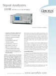
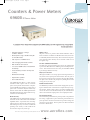
46891067.qxd
03/12/04
11:18
Page 1
Counters & Power Meters
6960B RF Power Meter
A precision Power Meter with comprehensive GPIB facilities for ATE requirements and standard
bench applications
•
Extensive frequency coverage:
30 kHz to 46 GHz
•
Wide dynamic range: -70 dBm (100 pW)
to +44 dBm (25 W)
•
Fast response on GPIB of 25 ms
•
Auto averaging with manual override
•
Both 50 Ω and 75 Ω sensors
•
Low sensor VSWR reduces measurement
uncertainty
•
Sensor linearity correction for improved
accuracy
•
Maximum hold facility
•
Optional DC operation
•
Non-volatile memory
The 6960B RF Power Meter is a high accuracy
instrument which together with its associated
power sensors provides measurements at frequencies from 30 kHz up to 46 GHz over a wide range of
power levels. Its numeric keyboard enables easy
manual control while full GPIB implementation
with SRQ mask and trigger modes make it the logical choice for fast ATE systems.
Meter Accuracy
The 6960B features an instrumentation accuracy of
better than ±0.5% in linear mode and ±0.02 dB in
logarithmic mode. A special auto zero circuit digitally stores the zero offset for each of the five ranges,
thus reducing zero carry over errors to ±0.03% and
providing a zero accuracy of ±1% of FSD on the
most sensitive range for any sensor type.
High Accuracy
All power sensors are provided with detailed calibration data to
0.01% resolution. In addition to Calibration Factor data, each sensor
is individually calibrated for linearity. When entered into the power
meter, this data reduces linearity errors to less than ±0.5% even on
the highest range.
Precision Calibration Attenuators
The 6920 series of high sensitivity power sensors are supplied with
a precision 30 dB attenuator for calibrating to the internal power reference. These attenuators have an accuracy of ±0.05 dB at 50 MHz
to provide high calibration accuracy.
Duty Cycle Correction
Although the 6960B is a true average power measuring instrument, it
may still be used for pulsed power measurements. The duty cycle of
the signal to be measured may be entered in the range 100 to 0.001%.
The power meter calculates the peak power by dividing the measured
average power by the duty cycle.
Relative Measurements
The dB REL key enables the measurement of high powers by entering the calibrated value of an attenuator or coupler directly as a negative number. Positive relative values to account for amplifier gains
can also be entered. The dB offset facility may be used with linear
units so that transmitter output powers can be displayed in Watts.
Two Power-Up Modes
The instrument is provided with two power-up modes. For production
line testing, or applications in power monitoring at unattended sites,
power-up mode 2 returns the instrument to its previous settings after
switch-off or a power failure. Power-up mode 1 sets all the instrument
functions to default values.
For the very latest specifications visit
www.aeroflex.com
46891067.qxd
03/12/04
11:18
Page 2
Two Proportional Voltage Outputs
Two analog voltage outputs proportional to RF input power are provided on the rear panel. The Recorder Output offers the full 50 dB
dynamic range of the instrument in the dB mode at 1 volt/decade for
wide range power measurements. In the Watts mode this output provides 0 to 5 V linear voltage proportional to the RF input power.
The fast Levelling Output provides 1 V per range for effective power
levelling of sweepers or signal sources. The calibration and linearity
correction data from the sensor are traded off for a fast response. For
semi-automated testing, a rear panel BLANKING output is provided
to turn off a source or sweep generator during AUTO ZERO operation
of the meter.
SRQ Response
To the system user, the SRQ response is always important and in the
6960B the SRQs have been arranged to form a mask with each SRQ
option having a binary weighting: 1 on end of measurement, 2 on
error, 4 on end of GPIB operation. SRQ option 4 is useful to inform
the controller that the requested GPIB operation such as Autozero
has been executed.
Self-Test
Self-test is initiated when the instrument is switched on and the
validity of the information in the non-volatile memory is automatically checked. The LCD alpha-numerics and annunciators can also be
verified using a coded key press.
Ease of Use
With its conventional calculator style keyboard, changing parameters
is both precise and obvious to the new user. Displayed units may be
either linear (mW) or logarithmic (dBm). Applications which require
circuit adjustments to optimise output or tune for a null are conveniently achieved with the analog meter. Automatic signal averaging is
provided as well as auto ranging. The power meter selects the most
appropriate amount of averaging in conjunction with the range in use.
Reliability
The 6960 series has a proven record of high reliability. Data from
service records show its actual mean time between failures (MTBF)
to exceed 120,000 hours. Conservative component ratings, liquid
crystal display and switch mode power supply for low internal heat
generation, contribute to this excellent reliability. Consequently, a two
year warranty is offered as standard with an optional third year warranty available at the time of initial order.
External DC Operation
For operation in remote locations and for certain military applications
an optional external DC supply input is available. Any voltage within
the range 11 to 32 volts can be accepted, operation from a vehicle DC
supply is thus possible.
Fast and Easy Servicing
To make servicing easy and fast, careful thought has led to a simple
arrangement of components and adjustments. Selective key switch
operations can access the filter and digital to analog converters to
check their operation, eliminating the need for a range calibrator.
The only test equipment required to assist servicing is a countertimer, digital voltmeter and screwdriver.
Optimum Noise Operation
For applications needing a fast response on a sensitive range, the user
can trade off resolution for speed by entering a lower average number.
The 6960B accepts average numbers between 1 and 256, so optimum
noise reduction or required response time are always available.
Non-Volatile Memory
Nine non-volatile stores are available for storing complete instrument
settings.
Maximum Hold
Long term drift measurements are easily made with the ‘maximum
hold’ facility which enables the maximum value of a changing signal
to be retained.
Automatic Sensor Recognition
The power meter contains a special sensor recognition circuit so that
the correct scaling is selected automatically when the power sensor is
connected.
GPIB Operation
6960B has been specifically designed with the requirements of the
ATE system designer in mind. The GPIB interface has been optimized both in terms of hardware and software allowing greater speed
in measurements with selectable resolution. Up to 40 readings per
second are possible. The GPIB program codes feature simple
mnemonics, requiring either a single digit number entry with no terminator or floating point entry requiring a terminator.
Six Trigger Modes
Specific GPIB program codes include TR-trigger mode. This sets
the trigger mode or starts a measurement after a hold condition. Up
to six trigger modes are available from the 6960B, from free running
fast to an immediate trigger with settling time then hold.
Low Cost of Ownership
Due to the modular design with good accessibility, mean time to
repair (MTTR) is just 20 minutes thus keeping the cost of ownership
low for the entire life of the instrument.
SPECIFICATION
FREQUENCY RANGE
30 kHz to 46 GHz depending on sensor used.
POWER RANGE
–70 dBm (100 pW) to +44 dBm (25 W) depending on sensor used.
POWER REFERENCE
0 dBm (1 mW), 50 MHz, Type N female precision connector, 50 Ω.
Adapters are supplied for other connectors with the power sensor.
Uncertainty
±0.7% traceable to National Standards.
Accuracy
±1.2% worst case for one year.
DISPLAY
Four digit LCD.
Over-range, Remote, Peak, Under-range, dB, dBm, dB REL, nW to kW,
Zero.
INSTRUMENTATION ACCURACY
Watts mode
±0.5%.
dBm mode
±0.02 dB.
dB REL mode
±0.02 dB.
ZERO
Set ±1% of FSD on most sensitive range.
46891067.qxd
03/12/04
11:18
Page 3
Carryover ±0.03% of FSD (when zeroed on most sensitive range).
Drift ±0.1% of FSD (±2% 6920 series) on range 1 (most sensitive)
over 1 hour at constant temperature after 24 hour stabilization.
Decrease by factor 10 for each higher range.
Power Up
Displays power-up mode currently in use. In power-up mode 1, instrument assumes default settings. Power-up mode 2 reinstates the settings in use at power down.
Linearity Factor
NOISE
Less than 1% of FSD (2% for 6920 series) for most sensitive range
with an average factor greater than 19.
Provides data entry for individual sensor linearity data to improve accuracy.
Duty Cycle
OUTPUTS (BNC socket)
Fast levelling
0 to 1 V each range, 1 kΩ impedance, excludes correction for Cal
Factor, Linearity Factor and Average Number. (For external levelling of
RF source.)
Enables entry of duty cycle of pulsed signal in range 100% to 0.001%.
The 6960B calculates the peak value of the pulsed signal from the
average power measured by the sensor.
‘Peak’ annunciator displayed when duty cycle <100%.
Calibration Factor
Recorder
±1%.
dB mode: 1 V/decade, 7 V maximum on range 5.
Watts mode: 5 V linear.
Fully corrected for Cal Factor, Linearity Factor and Average Number
(For plots of the full 50 dB dynamic range).
Blanking
Allows entry of sensor calibration factor in range 100% to 0.001 %.
Local
Returns instrument to ‘local’ front panel operation when remotely
addressed unless ‘local lock out’ is employed. In manual operation,
displays current GPIB address.
Auto Zero
Maximum voltage: 25 V Maximum current: 50 mA, open collector,
short circuit for blank.
Initiates zero routines to store zero offset for each of the 5 ranges.
Auto Cal
RESPONSE TIME
Initiates self-calibration routine after connection of sensor to Power
Reference.
Range 1 (most sensitive) 1 s, selectable.
Ranges 2 to 5 250 ms (display update), selectable 25 ms using GPIB.
GENERAL
Power Ref
Toggles internal 0 dBm (50 MHz) power reference on and off.
Resolution
GPIB INTERFACE
GPIB unit built into instrument if option 001 is ordered.
All front panel functions are remotely programmable except for test
modes.
KEY FUNCTIONS
Units
Selects either linear (mW) or logarithmic (dBm) units with toggle
action.
dB Rel
Displays current offset which may be entered in range -99 to +99 dB.
Store & Recall
Stores up to 9 complete instrument settings for any set-up condition
(eg Cal Factors at different frequencies); store 0 contains instrument
settings prior to last power down.
Resolution may be changed by altering the Average Number in the following format:Range
Resolution (dB) 0.1
0.01 0.001
Average Number
5 (highest power)
1
4
4
4
1
1
4
3
1
1
4
2
1
4
20
1 (lowest power)
4
20
50
ENVIRONMENTAL
Operating Temperature
0°C to 55°C.
Storage Temperature
–40°C to +70°C.
Storage Humidity
Up to 95% relative humidity at 35°C.
Altitude
Up to 2500 m (pressurized freight at
27 kPa differential, i.e. 3.9 Ib/in2).
Max Hold
Retains maximum reading of changing signal. When enabled, units
annunciators flash.
Range
Displays current range in use; ‘Au’ denotes auto ranging, ‘Hd’ indicates
held range. Any range may be selected and held at any time.
Averaging
ELECTROMAGNETIC COMPATIBILITY
Conforms with the protection requirements of the EEC Council Directive
89/336/EEC. Conforms with the limits specified in the following standards:
IEC/EN61326-1 : 1997, RF Emission Class B, Immunity Table 1,
Performance Criteria B
SAFETY
Enables any integer number in the range 1 to 256 to be set. In Auto
Averaging mode the following response times are obtained:
Range
Average No.
Response Time
5
1
0.25 s
4
1
0.25 s
3
4
1s
2
20
5s
1
50
12.5 s
For the very latest specifications visit
Conforms with the safety requirements of EEC Council Directive
73/23/EEC (as amended) and the product safety standard
IEC/EN 61010-1 : 2001 + C1 : 2002 + C2 : 2003 for class 1
portable equipment, for use in a Pollution Degree 2 environment. The
instrument is designed to be operated from an Installation Category 2
or 1 and 2 supply.
www.aeroflex.com
46891067.qxd
03/12/04
11:18
Page 4
54124/022
46881/365
46882/125
POWER REQUIREMENTS
AC supply
105 - 120 V~ (Limit 90 - 132 V~)
210 - 240 V~ (Limit 188 - 264)
Frequency: 50 - 400 Hz (Limit 45 - 440 Hz)
Power consumption: 50 VA maximum
DC supply
Power consumption: 20 W maximum
DIMENSIONS AND WEIGHT (over projections)
Height
108 mm
88 mm
Width
Depth
256 mm
369 mm
216 mm excluding feet and handles.
Weight
3.3 kg
VERSIONS AND ACCESSORIES
When ordering please quote the full ordering number information.
Ordering Numbers
Versions
6960B
RF Power Meter
Options
ordering)
Option 001
Option 002
Option 003
Option 004
POWER SENSORS - STANDARD
56910/900
10 MHz to 20 GHz (-30 dBm to +20 dBm) Type N.
56911/900
10 MHz to 20 GHz (-30 dBm to +20 dBm) APC 7.
56912/900
30 kHz to 4.2 GHz (-30 dBm to +20 dBm) Type N.
56913/900
10 MHz to 26.5 GHz (-30 dBm to +20 dBm) MPC
3.5.
56914/001
10 MHz to 40 GHz (-30 dBm to +20 dBm) 2.92 mm
56914/002
10 MHz to 40 GHz (-30 dBm to +20 dBm) 2.92 mm
plus waveguide 22 coax transition and calibration
table.
56914/003
10 MHz to 46 GHz (-30 dBm to +20 dBm) 2.92 mm
56919/900
75 Ω 30 kHz to 3 GHz (-30 dBm to +20 dBm) Type N
POWER SENSORS - LOW POWER
56920/900
10 MHz to 20 GHz (-70 dBm to -20 dBm) Type N.
56923/900
(Options must be specified at the time of
GPIB.
Rear sensor input.
Storage pouch mounted on top of instrument.
External DC operation.
Stowage Cover.
GPIB Manual H54811-010.
Service Manual (H6960B Vol. 2).
56924/001
56924/002
56924/003
2.92 mm.
10 MHz to 26.5 GHz (-70 dBm to -20 dBm) MPC
3.5
10 MHz to 40 GHz (-70 dBm to -20 dBm) 2.92 mm.
10 MHz to 40 GHz (-70 dBm to -20 dBm) 2.92 mm
plus waveguide 22 coax transition and calibration
table
10 MHz to 46 GHz. (-70 dBm to -20 dBm)
POWER SENSORS - HIGH POWER
Supplied with
46882/124
46882/123
43138/663
43138/154
AC Supply Lead.
Instruction Manual H6960B (Vol. 1).
Summary Card.
1.5 m Power Sensor Cable
DC Supply Lead (Option 004 only)
56930/900
56932/900
56934/001
56934/002
Accessories
54417/002
43138/664
43138/665
43138/666
43138/667
46884/501
46884/500
Waveguide 22 to 2.92 mm coax transition.
3 m Power Sensor Cable.
10 m Power Sensor Cable.
25 m Power Sensor Cable.
50 m Power Sensor Cable.
Rack Mounting Kit (Double Unit –3U High).
Rack Mounting Kit (Single Unit – 2U High).
56934/003
56930/002
56932/002
CHINA Beijing
Tel: [+86] (10) 6467 2761 2716
Fax: [+86] (10) 6467 2821
GERMANY
Tel: [+49] 8131 2926-0
Fax: [+49] 8131 2926-130
SCANDINAVIA
Tel: [+45] 9614 0045
Fax: [+45] 9614 0047
CHINA Shanghai
Tel: [+86] (21) 6282 8001
Fax: [+86] (21) 62828 8002
HONG KONG
Tel: [+852] 2832 7988
Fax: [+852] 2834 5364
SPAIN
Tel: [+34] (91) 640 11 34
Fax: [+34] (91) 640 06 40
FINLAND
Tel: [+358] (9) 2709 5541
Fax: [+358] (9) 804 2441
INDIA
Tel: [+91] 80 5115 4501
Fax: [+91] 80 5115 4502
UK Burnham
Tel: [+44] (0) 1682 604455
Fax: [+44] (0) 1682 662017
FRANCE
Tel: [+33] 1 60 79 96 00
Fax: [+33] 1 60 77 69 22
KOREA
Tel: [+82] (2) 3424 2719
Fax: [+82] (2) 3424 8620
As we are always seeking to improve our products,
the information in this document gives only a general
indication of the product capacity, performance and
suitability, none of which shall form part of any contract. We reserve the right to make design changes
without notice. All trademarks are acknowledged.
Parent company Aeroflex, Inc. ©Aeroflex 2004.
10 MHz to 18 GHz (-15 dBm to +35 dBm) Type N.
30 kHz to 4.2 GHz (-15 dBm to +35 dBm) Type N.
10 MHz to 40 GHz (-15 dBm to +30 dBm) 2.92 mm
10 MHz to 40 GHz (-15 dBm to +30 dBm) 2.92 mm
plus waveguide 22 coax transition and calibration
table
10 MHz to 46 GHz (-15 dBm to +30 dBm) 2.92 mm
10 MHz to 18 GHz (-5 dBm to +44 dBm) Type N
30 kHz to 4.2 GHz (-5 dBm to +44 dBm) Type N
UK Stevenage
Tel: [+44] (0) 1438 742200
Fax: [+44] (0) 1438 727601
Freephone: 0800 282388
USA
Tel: [+1] (316) 522 4981
Fax: [+1] (316) 522 1360
Toll Free: 800 835 2352
w w w.aeroflex.com
[email protected]
Our passion for performance is defined by three
attributes represented by these three icons:
solution-minded, performance-driven and customer-focused.
Part No. 46891/067, Issue 6, 04/04