1
INDEX
PAGE
ALIGNMENT
INSTALLATION
PARTS LIST
PRODUCTION
PAGE
INSTRUCTIONS
6-7
SCHEMATIC
DATA....
1
4-5
TOP VIEW — TUBE LAYOUT. . . 2
TRIMMER LOCATIONS
6
4
VOLTAGE
CHANGES
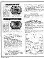
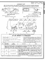
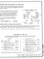
BUILT-IN "ROTO-SCOPE" ANTENNA
The built-in "Roto-Scope" antenna is operated by the
antenna control lever which extends from the back of
the cabinet (near the top). Set the antenna control lever
in that one of its three positions (left, center, or right)
which gives the clearest picture.
When an external indoor or an outdoor antenna is
required, be sure to disconnect the built-in Roto-Scope
antenna leads from the antenna terminal board. When
disconnected, tape the Roto-Scope antenna lead lugs and
place them away from the chassis.
INPUT IMPEDANCE and TRANSMISSION LINES
The input impedance to the receiver is 300 ohm
balanced (between antenna terminals). When using a
300 ohm transmission line connect it across the antenna
terminals.
Input impedance between one antenna terminal and
chassis is approximately 75 ohms. When using 75 ohm
coaxial transmission line, connect the outer conductor
to the chassis and the inner conductor to either antenna
terminal; use the terminal which gives the most satisfactory picture on the weakest station.
FUSE LOCATION
The horizontal output circuit is fused with a % amp,
250 volt fuse, part ifr84A4-2. The fuse is located in the
back end of the high voltage compartment.
MEASUREMENTS
3
. . . 2,3
CHASSIS NOTES
Chassis used in the straight TV and combination
models differ in that the combination models have connectors for supplying power to the radio and the cabinet
pilot light.
To service the television chassis in combination models
with the radio disconnected, it will be necessary to complete the heater circuit by connecting a wire jumper
from pin "L" to pin "K". See plug and socket drawing
on schematic. Since the radio receives its power from
the television chassis, it cannot be operated without the
television chassis.
Important: If both the radio and television are
turned on at the same time, neither unit will operate.
PICTURE TUBE HANDLING PRECAUTION
Due to the high vacuum and large surface area of
picture tubes, great care must be exercised when handling these tubes. Shatterproof goggles and heavy gloves
should be worn while handling or installing a picture
tube. The picture tube must not be scratched or subjected to excessive pressure as fracture of the glass will
result in an explosion of considerable violence which
may cause personal injury or property damage.
HIGH VOLTAGE WARNING
High voltages are present throughout this receiver.
Operation with cabinet removed involves shock hazard.
Exercise normal high voltage precautions while working
with this set.
After the antenna is set properly, make all checks or adjustments given here to insure
best performance and ease in tuning, /f is especially important that the Channel
Slugs and Ion Trap be adjusted upon installation or servicing of every set.
For best results, all checks or adjustments should be made using a transmitted television
test pattern. A mirror placed in front of the picture tube screen will be of help in observing the picture while adjusting rear panel controls.
NOTE: If both radio and television are turned on in combination models, neither unit
will operate. Be sure set owner has been properly instructed on the operation.
©John F. Rider
^Pc^^ArKCTURE'i
Tune in a picture as instructed in the customer instruction leaflet; note illustrations on interference effects.
ABJUST CttANMIU SLUGS
Individual channel oscillator adjustment of
every receiver should be checked upon installation or servicing. If this adjustment is properly
made, it is possible to tune from one station to
another by merely turning the CHANNEL control and if necessary, slightly readjusting the
TUNING control. With correct oscillator channel adjustment, best picture and satisfactory sound will be
located at the approximate center (half rotation) of the
range of the Tuning control.
This adjustment can be made without removing the
chassis from the cabinet. Adjust as follows:
a. Turn the set on and allow 15 minutes to warm up.
b. Set the CHANNEL knob for a station; set other controls for normal picture and sound.
c. Set TUNING control at center of its range by rotating
it approximately half-way.
d. Remove the CHANNEL and TUNING knobs.
e. Insert a %" blade, NON-METALLIC screwdriver in
the 14" hole (to the right of the channel tuning
shaft). For each channel in operation, carefully adjust the oscillator slug for clearest picture detail.
Then check sound, and if necessary readjust for minimum buzz. Only slight rotation of the slug will be
required; turning the slug in too far will cause the
slug to fall into the coil. (If an oscillator slug should
fall into the channel coil, remove the coil, move the
slug retaining spring aside, lightly tap the open end
of the coil against a solid object until the slug slips
out. Replace slug and set the slug retaining spring
into its cut-out slot.)
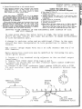
These sets use a 16TP4 or 16RP4 picture tube. If the
set has the 16TP4 tube, locate the ion trap on the neck
of the tube with the blue sleeve on top and the magnet to
the left (facing rear of chassis). With the 16RP4 tube,
locate the blue sleeve to the left and the magnet at the
bottom. Starting from a point close to the tube base,
very carefully move the ion trap forward or backward,
and at the same time rotate it slightly in either direction;
adjust for the brightest picture possible with the
BRIGHTNESS control set for average brightness.
Note that there may be two locations where the brightest picture can be produced. The second ion trap location,
which is further forward on the tube neck, should not
be used.
Important: Should the corners of the picture become rounded off or shaded after adjusting the ion trap,
correct this by moving the deflection yoke coil "E" as far
forward as possible and then adjusting the picture positioning lever (or the focus coil if necessary) as described
below. Do not try to remove shaded corners with adjustment of the ion trap. Be sure to readjust the ion
trap after adjusting the picture positioning lever or repositioning the focus coil.
The 16TP4 picture tube uses ion trap, part number
94A15-2; the 16RP4 tube uses ion trap, 94A15-1. The
part number is stamped on the ion trap magnet. The
wrong ion trap may cause shaded corners or insufficient
picture brightness.
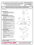
HEIGHT
"WIDTH
Chassis Views Showing Adjuslmenl Locations.
E (DEFLECTION YOKE COIL)
PICTURE POSITIONING LEVER
OSCILUTOR TUNING
SLOG ADJUSTMENT
B
Control Panel; CHANNEL and TUNING Knobs Removed.
ION TRAP
'BLUE SLEEVE
ADJUST THE ION TRAP
In order to prolong the life of the picture tube,
it is important that this adjustment be made on
every receiver upon installation or servicing.
f*»
'
... FUSE
I XINSIOE
HOUSING
MODELS 36R37, 36Rli5, 36R1+6,
Oh. 21B1, 21C1, Radio Ch. 5D2
If the picture is
tilted, loosen the
wing nut "H" on the
deflection yoke coil
and slightly rotate
the yoke "E" until
the p i c t u r e i s
straight. Before
tightening the wing
nut, be sure that the
yoke is moved as far
Picture Tilted; Adjust
Deflection Yoke Coil.
forward as possible,
otherwise corners of the picture may become shaded.
b. Push the deflection yoke coil "E" as far forward as
possible. In some cases, it may be necessary to loosen
the two yoke bracket support screws '"D" at the sides
of the upper mounting bracket, move the bracket
up or down, and then move the deflection yoke coil
as far forward as possible.
Shaded corners may also result from use of the wrong
ion trap. The 16TP4 picture tube uses ion trap 94A15-2;
the 16RP4 picture tubes uses ion trap 94A15-1. The
part number is stamped on the ion trap magnet.
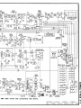
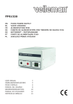
SCHEMATIC NOTES
LJJ.LU.UJ etc. are run numbers and indicate a production
change. Run numbers are rubber stamped at rear of chassis.
etc. indicate alignment points and alignrnent connections.
If the picture is
off center, it can be
centered by using
the picture positioning lever, and when
necessary, re-positioning the focus
coil around the picture tube neck. Follow the instructions
Picture Not Centered; Adjust
given below. Note
.Picture Positioning Lever.
that the picture
positioning lever can be moved sideways, or up
and down.
Picture Slightly Off Center
a. Adjust ion trap as instructed on preceding page.
b. Slightly loosen the screw "A" which locks the picture
positioning lever to the focus coil, adjust the lever
for correct picture centering.
c. Readjust the ion trap.
Picture Greatly Off Center
a. Adjust ion trap as instructed on preceding page.
b. Slightly loosen the two screws "B" which hold the
focus coil to the yoke bracket. Center focus coil
around the tube neck; tighten screws.
c. Loosen the screw "A" and center the picture with the
picture positioning lever. If the picture cannot be
centered with the lever, it may be necessary to locate
the focus coil slightly off center and then center the
picture with the picture positioning lever.
d. Readjust the ion trap.
Difficulty in Centering Picture or
Eliminating Shaded Corners
a. Loosen screws "G", then move the yoke support
bracket forward until rubber grommet "F" is firmly
against the flare of the picture tube.
©John F. Rider
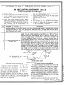
TV VOLTAGE DATA
(Voltages given on schematic diagram)
• PICTURE control turned fully clockwise. CHANNEL control set on an unused channel. Other front controls set at
approximately half rotation. Vert. Lin. and Height set at
approximately half rotation.
• Voltages marked with an asterisk * will vary widely with
control setting.
In combination models, B-f- voltages in TV chassis will be
slightly higher when set is switched to radio position. Alternate voltage readings for radio and TV are shown for sound
output tube V204 (6V6GT).
• Line voltage 117 volts AC.
• Voltages measured with a vacuum tube voltmeter between tube
socket terminals and chassis, unless otherwise indicated.
Voltages at VlOl, V102, V306 measured from top of socket
with tube removed.
n
858
I6TP4
OR
16RP4
SOUND
AMP.
OSC. i MIXER
6J6)
SOUNC
OUTPUT
JF AMP.
6AG5, 6 B C 5 > 6 C B 6
VERT. OSC./6SN7
4 SYNC. 1NV.V CT
6BQ6,
SOUND IF
' 5U4
RECTIFIER V 6
HOR. O U T P U T '
T
J IA1 AMP. 250V. FUSE
Top View of Chassis.
MODELS 36R37, 36RJ4-5,
36RI+6, Ch. 21B1, 21C1
• Antenna disconnected from set with terminals shorted.
• Under operating conditions, AGC (Automatic Gain Control)
voltage developed at pin 1 of V301 (6AU6) should measure
approximately —3 volts. This voltage depends on picture
signal strength and Picture control setting.
CAUTION
Pulsed high voltages are present on the cap of the 6BQ6GT
tube, and on the filament terminals and cap of the 1B3GT tube.
NO ATTEMPT SHOULD BE MADE TO TAKE MEASUREMENTS FROM THESE POINTS UNLESS SUITABLE TEST
EQUIPMENT IS AVAILABLE.
Picture tube 2nd anode voltage can be measured from the 2nd
anode connector and should be taken only with a high voltage
instrument such as a kilovoltmeter. 2nd anode voltage is approximately 12.5 KV. Proper filament voltage check of the 1B3GT
tube may be made by observing filament brilliancy as compared
with that obtained with a 1.5 volt dry cell battery.
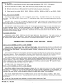
RAD|O VOLTAGE DATA
(Voltages given on schematic diagram)
• Line voltage 117 volts AC.
• Voltages measured with a vacuum lube voltmeter, between tube
terminals and chassis.
• Voltages measured with band switch on FM position, unless
otherwise indicated; an AM reading is given where difference
is significant.
• Volume control set at minimum.
• Dial turned to low frequency end.
• Antennas disconnected.
A When R602 is 240 ohms, voltage on pin 1 of V601 is 152 volts,
pin 2 is —.5 volts, pin 6 is 152 volts and pin 8 is 1.9 volts.
When R602 is 1500 ohms, voltage on pin 1 of V601 is 160 volts,
pin 2 is —3 volts, pin 6 is 160 volts and pin 8 is 3 volts.
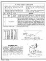
IMPROVED NOISE IMMUNITY IN THE HORIZONTAL SYNC CIRCUIT OF 21B1
AND 21C1 CHASSIS
In some areas where the noise level is high, the noise peaks may
affect the sync sircuit and cause the picture to shake horizontally
or lose horizontal sync.
A change in resistor value and an additional filter in the sync
circuit has- been incorporated in late production to reduce this
trouble.
The circuit change began with run 2 of 21B1 chassis and run 5 of
21C1 chassis.
Early production receivers may be modified by following the procedure given below:
1. Locate a 9 lug terminal atrip adjacent to the vertical output
transformer.
2. Remove R323 (8200 ohms) from lugs 1+ and 6.
3. Connect an 18,000 ohm 1/2 watt resistor (part number 60B8-183)
between lugs 5 and 6.
li. Connect a lij.0 |_i,(j,fd condenser (part number 65B1-26 with a 2?OK
1/2 watt resistor, (part number 60B8-27i|) in parallel between lugs
ij. and 5 •
Tl^.02
VERTICAL OUTPUT
TRANSFORMER
REMOVE
R323N
8.2K
ADD
2?OK
1/2 WATT
ADD
llj.0 MMFD
ADD
l8K",l/2 WATT
(REPLACES R323)
5
o
m
<»>
ro
o
6BA6
6BA
lsnr
,«*ri,
V602 /«'>»
F—
/*
< N=
^/'
i,°" s [,j" T'""" *\— siHirvM
ft.
T
"
!-//(«
'SJI
-^
,/,'—-)
p'
...J
6AU6
I'
TNZIO.IF-i
V603
T602 _
6AL5
1506
«J09
lUIHEf S1ITCH SEIIHt SEIECIS Pill OF
COILS LIOI 1 1102 FOR CH1MF.L DESIRED.
tu nifi mrtcfs f/cfrr mtr "w"it[
1\. OR 6CB6l\" "" '<"">l""" '"" """•
' -
6AU6
2HD. VIDEO IF
V30Z
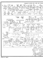
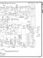
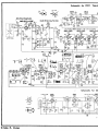
Schematic for 21 Bl, 21CT
RECORD CHANGERS: Model RC500, See page
ROD.CH.21-1; Hodel RC550, See page
^GD.CH.21-9.
©John F. Rider
, ;
'
'•-
6AU6
3RD. VIDEO IF
V303
T
Television Chassis; 5
A6
•-MHO.OET.
03 Hern
6AL5
FI HATH DEIKIOI
V604
C30)
ii
rue nmets
w/// «w run :xifr.
faarr ifwret F/KI
>
a
70
>
r-
H
<
2
O
5D2 radio circuit and connections also shown.
cn
i
MODELS 36R37, 36RJ+5, 36R46,
CM
Ch. 21B1, 21C1, Radio Ch. $D2
PRODUCTIC>N CH>\NGES
RUN 1 in 21C1 CHASSIS
Resistor R430 was changed from 12,000 ohms, % watt to
12,000 ohms, 2 watt (part #60820-123). This change was made
to prevent possible increase in resistance of R430 due to increased power dissipation.
RUN 2 in 21 Cl CHASSIS
In early sets R210 was 270,000 ohms; R211 was 100,000 ohms.
In later sets R210 was changed to 150,000 ohms, % watt (part
#6088-154) ; R211 was changed to 47,000 ohms, M> watt (part
#60881-473). This change resulted in improved audio response
on rad io operation.
RUN 3 in 21C1 CHASSIS
Conelenser C433, .002 mfd, 600 volts (part #6485-14) was
added across width control L402 to increase sweep width.
INTERFERENCE TRAP ADDED
Late r production sets have an Adjacent Channel Interference
Trap iidded between the connector lug (terminal of C113) on
and pin 1 of 1st video IF amplifier V301 (6AU6) .
the T\sr tuner
ti
ap consists of L307 and C314; it has part number 72A102.
IMPOIR T A N T
This preliminary service data contains the compl ete electr ical parts list for models using the 21B1, 21C1
television chassis and for the 5D2 (AM-FM) radio ch assis. It also includes cabinet parts for models 36R37,
36R45, 36R46. It contains alignment data for the tel evision c lassis .
This TV chassis uses a 16" rectangular picture tiibe. It us es an improved intercarrier sound system
(adjacent channel trap and improved sound take-off) ind Autoniatic Gain Control circuits which are similar
to the 20X1, 20Y1, 20Z1 chassis. Sweep circuits are similar to 24D1, 24E1, 24F1, 24G1, 24H1 chassis.
Model RC500 or Model RC550 record changer is L sed.
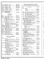
21B1, 21C1, 5D2 CHAS SIS PARTS
RESISTORS
Sym.
tRIOl
R102
R103
R104
TR105
R106
R107
TR108
R109
R201
R202
R203
R204
R205
R206
R207
R208A
R208B
Description
3 900 ohms
1/2 watt
4, 700 ohms, 1/2 watt
Par t No.
..98A 45-16
45-17
QQ A 45-18
QQ A 45-19
%Ts , D 98A 45-20
Qfl A 45-21
no A 45-18
98A 45-20
QQ A 45-67
RHR
8-474
82 ohms, 1/2 watt, carbon
1 000 ohms 1/2 watt
390 ohms, 1/2 watt . „
60S 28-31
60B 8-102
. .60B 8-391
fiOR 7-103
fifiR 7-103
RflR 8-473
R209
R210
R211
R212
R213
250,000 ohms, Volume!
. .75B 11-16
1,500 ohms, Picture/ '
(R208 includes switch SW501)
GOB 8-475
fiDR 8-154
8-473
GOB 8-105
GOB 14-331
R301
R302
R303
R304
R305
R306
R307
R308
10 000 ohms 1/2 watt 5%
1,000 ohms, 1/2 watt
1 000 ohms 1/2 watt
1 , 000 ohms 1/2 watt
47 ohms, 1 watt
18 000 ohms 1/2 watt
1 000 ohms 1/2 watt
68 ohms, 1/2 watt, carbon
R309
R310
R311
10 000 ohms 1/2 watt 5%
1 000 ohms 1/2 watt
150 ohms 1/2 watt
GOB
. .GOB
60B
.' . .60B
. .GOB
• -GOB
GOB
GOB
GOB
GOB
.fiOR
7-103
8-102
8-102
8-102
14-470
8-183
8-102
28-44
7-103
8-102
8-151
R312
R313
R314
R315
R316
R317
R318
R319
R320
R321
R322
R323
R324
R325
R326
R327
R328
1,000 ohms, 1/2 watt
. .GOB 8-105!
560 000 ohms 1/2 watt
. . . .60B 8-564
.GOB 8-684
680 000 ohms 1/2 watt
. .GOB 7-472
4, 700 ohms, 1/2 watt, 5%.
. . See R208B
Picture control
. .GOB 20-473
47, 000 ohms, 2 watt
. .GOB 20-563
56,000 ohms, 2 watt
3, 000 ohms, 15 watt, candohm . . .. 61A 3-14
. .Part of L303
33, 000 ohms, 1/2 watt
. .Part Of L304
10, 000 ohms, 1/2 watt
. .60B 20-472
4,700 ohms, 2 watt
. .60B 8-822
8, 200 ohms, 1/2 watt
680 000 ohms 1/2 watt
. . . . . .60B 8-684
.60B 8-564
560 000 ohms 1/2 watt
. .60B 8-104
100, 000 ohms, 1/2 watt
75B 13-12
100 000 ohms Brightness
22 , 000 ohms , 1/2 watt . . . . . . . . . . .60B 8-223
R401
R402
R403
R404
R405
R406
R407
R408
R409
R410
R411
R412
R413
R414
R415
R416
R417
R418
R419
R420
R421
R422
R423
R424
R425
. .GOB 8-223
. .GOB 8-822
. .608 8-822
60B 8-155
75B 13-14
. .GOB 8-105
1 megohm , 1/2 watt
. .60B 8-822
8, 200 ohms, 1/2 watt
2 . 5 megohms, Height
. .75B 13-3
. .60B 8-105
1 megohm, 1/2 watt
. .75B 13-7
3,000 ohms, V e r t . Lin
820 ohms, 1/2 watt
. .GOB 8-821
560 ohms 1/2 watt
. . . . . . . .60B 8-561
560 ohms, 1/2 watt
. .60B 8-561
. .60B 8-225
2 . 2 megohms , 1/2 watt
820 ohms, 2 w a t t . .
..60B 20-821
60B 8-225
18 000 ohms 1/2 watt
60B 8-183
47 000 ohms 1 watt
60B 14-473
2 200 ohms 1/2 watt
60B 8-222
27 000 ohms, 2 watt
60B 20-273
8. 2 megohms, 1/2 watt
. .60B 8-825
15, 000 ohms, I w a t t .
60B 14-153
1,000 ohms, 1/2 watt
60B 8-102
2 200 ohms 1/2 watt
60B 8-222
12, 000 ohms, 2 watt
. .GOB 20-123
22, 000 ohms, 1/2 w a t t . . . .
8, 200 ohms, 1/2 watt
8,200 ohms, 1/2 watt
tTo secure proper high frequency character istics, oj-der exact part from Admiral distributor or use IRC
me talized resistor only.
©John F. Rider
R426
R427
R428
R429
R430
R431
R432
R433
R434
R435
R436
R437
R438
R439
100,000 ohms, 1/2 watt, 5%
60B 7-104
100,000 ohms, 1/2 watt, 5%
60B 7-104
470,000 ohms, 1/2 watt
60B 8-474
4 . 7 megohms, 1/2 watt
60B 8-475
12,000 ohms, 2 watt
60B 20-123
5,600ohms, 1/2 watt
60B 8-562
1,500 ohms, 1/2 watt
60B 8-152
120,000 ohms, 1/2 watt
60B 8-124
25,000 ohms, Hor. Hold
75B 13-13
8,200 ohms, 1 watt
60B 14-822
150,000 ohms, 1/2 watt
60B 8-154
1 megohm, 1/2 watt
60B 8-105
8, 200 ohms, 1/2 watt
.60B 8-822
68 ohms, 1/2 watt, carbon
resistor only
60B 28-44
R440 47 ohms, 1/2 watt, carbon
resistor only
60B 28-45
R441 82 ohms, 1/2 watt, carbon
resistor only
60B 28-31
R442 6, 800 ohms, 2 watt
;
.60B 20-682
R443 2.7 ohms, 1/2 w a t t . . . .
60B 28-47
R444 470,000 ohms, 1 watt
60B 14-474
R445 1,000 ohms, 1/2 watt
60B 8-102
R446 750 ohms. Focus
75_B 13-16
R501 270,000 ohms, 1 watt
60B 14-274
R502A 2,725 ohms, 2.5 watt"!i-candohm... 61A 5-8
R502B 2, 650 ohms, 10 watt/
[240 ohms, 1/2 watt, 5% (used in
early 5D2 sets)
60B 7-241
R602
1,500 ohms, 1/2 watt (used in
|_ late 5D2 sets)
60B 8-152
Before replacing, see 5D2 production change on reverse side.
R603 22,000 ohms, 1/2 watt
60B 8-223
R604 470 ohms, 1/2 watt
60B 8-471
R605 820 ohms, 1/2 watt
.Part of L606
R606 470 ohms, 1/2 watt
60B 8-471
R607 22 ohms, 1/2 watt
60B 8-220
R608 1 megohm, 1/2 watt
60B 8-105
R609 6, 200 ohms, 1/2 watt, 5%
SOB 7-622
R610 470,000 ohms, 1/2 watt
60B 8-474
H611 10,000 ohms, 1/2 watt
60B 8-103
R612 1,000 ohms, 1/2 watt
60B 8-102
R613 47,000 ohms, 1/2 watt
60B 8-473
R614 390 ohms, 1/2 watt
60B 8-391
R615 27,000 ohms, 1/2 watt
60B 8-273
R616 15,000 ohms, 1/2 watt
60B 8-153
R617 15,000 ohms, 1/2 watt
60B 8-153
R618 100,000 ohms, 1/2 watt
60B 8-104
R619A 1 megohm, Volume"!
,
L
, „.,. ,, .„
R619B 2 megohms, Tone J-D>»l control. . 75B 11-12
(R619 includes on-off switchSW603)
R620 10 megohms, 1/2 watt
.60B 8-106
R622 560,000 ohms, 1/2 watt
.60B 8-564
R623 22 ohms, 1/2 watt
60B 8-220
R627 1,000 ohms, 1 watt
60B 14-102
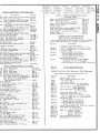
CONDENSERS
Sym.
C101
Description
Part No.
5 mmfd, +.5 mmfd, Zero temp.
coeff
98A 45-22
C102 .5 to 3 m m f d , ceramic trimmer. . .98A 45-87
C103 .001 mfd. min, ceramic
98A 45-24
C104 .5 to 3 m m f d , ceramic trimmer. . .98A 45-23
C105' 120 m m f d , 5%, ceramic,
-750 temp, coeff
98A 45-25
C106 100 m m f d , ceramic, -750 temp.
coeff
98A 45-26
C107 .5 to 3 m m f d , ceramic trimmer. . .98A 45-23
C108 20 m m f d , Cer . Zero temp . coeff.. .98A 45-27
C109 10 mmfd, 5%, ceramic,
-750 temp, coeff
98A 45-79
C110 .5 to 3 m m f d , ceramic trimmer .. .98A 45-23
Clll .3 to 5 m m f d , fine tuning rotor.. . .98A 45-92
C112 10 mmfd, 5%, ceramic,
Zero temp, coeff
98A 45-64
C113 120 mmfd, 10%, silver mica
98A 45-78
C114 .001 m f d . m i n , ceramic
98A 45-24
C115 .001 mfd. min, ceramic
98A 45-24
C201
C202
C203
C204
C205
C206
6.8 mmfd, - .00033 temp, c o e f f . . .
20 mmfd, 5%, ceramic
.005 mfd, ceramic
180 mmfd, 5%, -.00003 temp.
coeff
500 mmfd, ceramic
4 m f d , 50 V . , electrolytic
65B 6-71
65B 6-51
65A 10-1
65B 6-59
65B 6-6
67A 4-9
MODELS 36R37,
36RJ+6, Ch. 21B1,
C207
C208
C209
C210
C211
C212
C213A
C213B
C213C
C214
.001 mfd, ceramic
.047 mfd, 200 volts, paper
.005 mfd, ceramic
50 mmfd, ceramic
.047 mfd, 400 volts, paper
.01 mfd, 400 volts, paper
20 mfd, 25 V7|
10 mfd, 25 V. [-electrolytic
10 mfd, 450 VJ
.005 mfd, 600 volts, paper
C301A
C301B
C302A
C302B
C303A
C303B
C304
C305
C306
C307A
C307B
C307C
C308
C309
C407C
C409
C410
C411
C412
C413
C414
C415
C416
C417
C418
C419
C420
C421
C422
C423
C424
C425
C426
C427
C428
C429
C430
C431
C432
C433
67C 15-19
.64B 5-12
65A17 - 2
.005 mid, ceramic
...............
120 mmfd, ceramic
..............
.22 mfd, 200 volts, paper .........
20 mid, 350 V7|
20 mfd, 350 V. ^electrolytic ......
60 mfd, 400 V.J
.047 mfd, 400 volts, paper ........
.1 mfd, 400 volts, paper ..........
.047 mffl, 400 volts, paper ........
.047 mfd, 600 volts, paper ........
•°° mf ]~~ dual ceramic
..........
C310
C311
C312A
C312B .004 mfdj
C313 .001 mfd, ceramic
...............
C314 120 mmfd, 3%, mica
.............
C401
C402
C403
C404
C405
C406
C407A
21C1
65B 6-41
64B 9-41
65A 10-1
65B 6-4
64B 9-28
64B 5-25
65A 10-1
65B 6-66
64B 8-37
67C 15-17
64B
64B
64B
64B
65A
9-28
5-20
9-28
8-9
17-1
65B 6-41
65B 1-10
.002 mfd, 600 volts, paper
64B 5-14
.005 mfd, 600 volts, paper
64B 5-12
.0047 mfd, mica
65B 21-472
.0047 mfd, mica
65B 21-472
.1 mfd, 600 volts, paper
64B 5-5
.047 mfd, 600 volts, paper
64B 8-9
100 mfd, 50 V7\B 20 mfd, 450 V. ^electrolytic
80 mfd, 350 vJ
.02 mfd, 400 volts, paper
.01 mfd, 400 volts, paper
Electrolytic
.001 mfd, mica
.001 mfd, mica
.47 mfd, 400 volts, paper
.005 mfd, 600 volts, paper
.047 m f d , 400 volts, paper
.01 mfd, 400 volts, paper
.0039 m f d , 5%, silver mica
330 mmfd, mica
330 mmfd, mica
470 mmfd, mica
Electrolytic
20 to 280 mmfd, trimmer,
Hor . Drive
Electrolytic
.047 mfd, 600 volts, paper
.25 m f d , 600 volts, paper
.02 mfd, 400 volts, paper
.047 m f d , 200 volts, paper
500 mmfd, 20, 000 V., ceramic
47 mmfd, 5%, 1,500 volts,
silver mica
.1 mfd, 400 volts, paper
Electrolytic
.0022 m f d , 600 volts, paper
67C 15-18
64B 5-24
64B 5-25
See C307B
65B 21-102
65B 21-102
64B 9-72
64B 5-12
64B 9-28
64B 5-25
65B 1-63
65B 21-331
65B 21-331
65B 21-471
See C213B
66A 30-1
See C213C
64B 5-7
64B 5-3
64A 2-9
64A 2-8
65B 18-5
65B 1-64
64A 2-10
See C307C
64B 9-11
C601 2 to 20 mmfd, trimmer
Part of L601
C602 .001 m f d . min, ceramic
65B 6-41
C603A 486 mmfd. (max.) AM RF^\B 15 mmfd. (max.) FM RF I
C603C 114 mmfd. (max.)AMOsc.> g a n g -" 6 8 B 2 4
C603D 15 mmfd. (max.) FM Osc.J
Dial drum spotwelded to gang.
C604 .01 mfd. min, ceramic
65A 10-3
C605 .68 mmfd, ceramic
65A 16-1
C606 40 mmfd, ceramic,
-.000750 temp, coeff
65B 6-67
C607 .001 mfd, ceramic
65B 6-41
C608
C609
C610
C611
C612
C613
C614
C615
C616
C617
C618
C619
C620
C621
C622
C623
C624
C625
C626
C627
C628
C629
C530
C631
C632
C633
C634
C635
C636
C637
C638
C639
C641
40 mmfd, silver mica (used in
early 5D2 sets)
65B 1-65
30 mmfd, silver mica (used in
late 5D2 sets)
65B 1-69
Before replacing, see 5D2 production change on reverse side.
.001 mfd, silver mica, 5%
.Part of T604
.01 m f d . min, ceramic
65A 10-3
.01 m f d . min, ceramic
65A 10-3
100 mmfd, silver mica, 5%
Part of T601
300 mmfd, silver mica, 5%
Part of T604
.01 m f d . min, ceramic
65A 10-3
.01 m f d . min, ceramic
65A 10-3
.01 mfd . m i n , ceramic
65 A 10-3
250 m m f d , ceramic
65B 6-5
200 mmfd, silver mica, 5%
Part of T605
100 mmfd, silver mica, 5%
Part of T602
200 mmfd, silver mica, 5%
Part of T605
.01 m f d . m i n , ceramic
65A 10-3
.01 m f d . m i n , ceramic
65A 10-3
100 mmfd?)
,
co . „ ,
100 mmfd j d u a l c e r a m . c
63A 7-1
If a section of this dual condenser becomes
defective, replace with exact duplicate or two
condensers of the same value with a tolerance
within 10% of each other.
4 m f d , 150 volts, electrolytic
67A 4-2
.001 m f d . m i n , ceramic
65B 6-41
.01 m f d . m i n , ceramic
65A 10-3
100 mmfd, ceramic, -.000750
temp, coeff
65B 6-68
.001 m f d , ceramic
65B 6-41
.01 m f d . m i n , ceramic
65A 10-3
.1 mfd, 400 volts, paper
64B 1-20
.005 m f d . min, ceramic
65A 10-1
5 mmfd, ceramic
65B 6-61
2 .5 to 6 m m f d , ceramic trimmer . .66A 28-1
90 m m f d , silver mica, 3%
Part of T603
•°n°* mlrd' min '| dual ceramic. . . . 65A 17-1
.004 m f d . min.J
.01 m f d . m i n , ceramic
65A 10-3
.01 m f d . m i n , ceramic
65A 10-3
.1 mfd, 400 volts, paper
64B 1-20
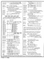
COILS and TRANSFORMERS
Sym.
L101
L102
L103
L104
L105
L201
L301
L302
Description
Part No.
Antenna Coil
for Channel #2
98A 62-2
for Channel #3
98A 62-3
for Channel #4
98A 62-4
for Channel #5
98A 62-5
for Channel #6
98A 62-6
for Channel #7
98A 62-7
for Channel #8
98A 62-8
for Channel #9
98A 62-9
for Channel #10
98A 62-10
for Channel #11
98A 62-11
for Channel #12
98A 62-12
for Channel #13
98A 62-13
Mixer-Oscillator Coil
for Channel #2
98A 63-2
for Channel #3
98A 63-3
for Channel #4
98A 63 -4
for Channel #5
98A 63-5
for Channel #6
98A 63-6
for Channel #7
98A 63-7
for Channel #8
98A 63-8
for Channel #9
98A 63-9
for Channel #10
98A 63-10
for Channel #11
98A 63-11
for Channel #12
98A 63-12
for Channel #13
98A 63-13
Before inserting replacement, coil L101 or
L 102, see that teeth at inner end of coils fit together when fitted in detent plate at center of
t u r r e t . If necessary file teeth slightly.
Mixer Plate Coil
98A 45-77
Heater RF Choke
98A 45-13
Heater Oscillator Choke
98A 45-14
Sound Take-off Coil (includes
R201, C201, C202)
72B !
Video Peaking Coil
Video Peaking Coil
73A 5-12
73A 5-7
©John F. Rider
L303
Video Peaking Coil (wound on
R320)
Video Peaking Coil (wound on
R321)
Heater RF Choke
'
Heater RF Choke
Trap Coil (includes C314)
73A 5-9
73A 2-5
73A 2-5
72A 102
L402
L403
L404
Horizontal Lock Coil (includes
C418 and R431)
Width Control
Horizontal Linearity Control
Focus Coil
94A 17
94A 29-1
94A 28
69C 117-3
L601
L602
L603
L604
L605
L606
L610
AM Loop Antenna, includes C601. .69C 116-1
FM Antenna
AB195
FM Antenna Coil
69A 85
AM Oscillator Coil
69A 86-1
FM Oscillator Coil
69A 87
FM Peaking Coil (wound on R605). .73A 5-11
RF Dual Choke
69A 102
T201
T202
Ratio Detector Transformer
Audio Output Transformer
for 21B1 chassis
for 21C1 chassis
L304
L305
L306
L307
L401
T301
T302
T303
T401
T402
T403
T404
Blocking Oscillator Transformer. . 79A 18-2
Vertical Output Transformer
79B 29-1
Deflection Yoke (includes R412,
R413, R445, C430)
A3222
Horizontal Output Transformer
(includes tube cap clips)
79C 30-2
Power Transformer
T601
1st IF (FM) Transformer
for early 5D2 sets
for late 5D2 sets
Before replacing, see 5D2 production change on reverse side.
2nd IF (FM) Transformer
Ratio Del. Transformer
1st IF (AM) Transformer
for early 5D2 sets
for late 5D2 sets
Before replacing, see 5D2 production change on reverse side.
2nd IF (AM) Transformer
T605
72B 68
79C 33-1
79C 33-2
1st IF Transformer (includes
R306, R307, C302A, C302B)
72C 96-6
2nd IF Transformer (includes R309J72C 96-7
3rd IF Transformer (includes C305J72C 96-8
T501
T602
T603
T604
73A 5-13
80C 26-1
72B 98
72B 98-1
72B 97
72B 97-1
72B 94
Description
Part No.
.88A 5-6
Speaker Socket
.88A 5-5
Speaker Plug
Speaker
78B 59-1
5" PM
78B 49-1
8" PM
78B 56-2
12" PM
88A 1
M 204 Socket, Audio Input
M401 Horizontal Output Fuse, 1/4 a m p . ,
84A 4-2
250 volts
Fuse Holder
84A 5-1
89A 22-2
M501 Interlock Socket (Male)
M502 L i n e Cord, with interlock socket. . 89A 22-1
M503 Cable Socket (Combination
88A 20-2
models only)
SW501 Switch, On-Off Power ( S . P . D . T . ) . Part of R208
V306 Picture Tube
16RP4 or 16TP4
ISA 572
Bracket, Deflection Yoke Holding
Bracket, Picture Tube Mounting (Supports
front of picture tube)
Right side (facing tube)
15B 615-1
Left side (facing tube)
15B 615-2
M201
M202
M203
MISCELLANEOUS I
for TV TUNER 94C
72B 76
72B 39
MISCELLANEOUS PARTS for TV CHASSIS
Sym.
Bracket (for mtg. picture tube
focus coil)
Top
Bottom
Bracket, Tuner Shaft (Bakelit
Clamp, Picture Tube Front M
Bracket (clamps bracket tc
Clamp, Webbing (for mtg. pic
Clip, Tube Cap
for 6BQ6GT tube
for 1B3GT tube
Connector Lead, 2nd Anode (i
plug)
Cover, IF Strip
Fuse Holder
Insulating Plate (for 2nd anodi
condenser mtg.)
Ion Trap
for 16TP4 picture tube
for 16RP4 picture tube
Lever, Focus Coil Adjusting
Lock, 1B3 Mounting Shell Dis
Pilot Light (#47)
Pilot Light Socket (used in co
models)
Rubber Channel, 1" long (for
tube bracket)
Rubber Collar (mounted over
tube neck)
Rubber Grommet, 2nd Anode 1
Rubber Insert, 1" diamter (bo
side support of picture tube
Rubber Strip, Adhesive (3/161
used under webbing band)..
Shield, Tube
plain type
slotted type
Socket, Jewel Light
Socket, Shell (cover for 1B3 ti
Socket, Tube
miniature bakelite (7 p i n ) . .
octal, plain
octal, ringmount (mica filli
miniature (9 pin)
picture tube
Socket, Test (4 t e r m i n a l ) . . . .
Spring, Picture Tube Groundii
Tuner, Television (complete).
Webbing, Picture Tube Mtg. S
(42" length)
Sym.
M104
Description
Shaft Shell & Rotor Ass
Tuning) (with 4 1/16
brass shaft shell). .
M107 ' Bracket, Sharp Tuning
Retaining.
M108 Spring, Detent Plate Gl
M109 Shield, Tube (Slotted; f
MHO Shield, Tube (Plain; foi
M112 Spring, Slug Retaining
M113 Washer, Fibre Spacer
(1/4" IDxl/2" OD).
M114 Nut, Locking Spring (fo
M115 Screw,Trimmer (4-36;
M116 Screw, Bracket Mtg. (6
M117 Slug, Brass Tuning...
Mil8 Stator Plate (ungroundi
Ceramic Insulator,
ing Clll (includesm
M120 Tuner, Television (cor
M121 Roller, Detent (3/8" di
3/32" dia. bearing)
M122 Spring, Detent (2 5/16'
Ml23 Contact Plate and Brae
(Uses Wiping Contac
M124 Spring, Sharp Tuning ]
(Flat bronze 1 7/16'
M125 Spring, Front and Real
(Wire 2 3/4" long, 3
M126 Turret and Shaft Asser
coils) (5 3/8" shaft
rounded detent depre
,be and
MISCELLANEOUS PARTS for 5D2 RADIO
15C 613
15C 614
32A 111-1
lite)
Mounting
to chassis). .. 15A 616
)icture tube). ,.15A 526
.88A 16-8
. 19A 54
(includes
.88A 16-7
.15B 641
.84A 5-1
Dde filter
.32A 135-1
ig
lisk
94A
94A
15B
15A
81A
15-2
15-1
574
589
1-8
combination
82A 11-58
3r picture
12A 9-11
\r picture
e Housing
bottom and
ibe)
6"x3/8"x2"
1
12B 40
12A 2-7
12A 16-1
12A 5-6
87A 7-7
98A 45-73
87A 6-3
I tube socket)..88A 27-1
I
illed)
ding
e)
. Strap
87A 3-7
87A 5-1
87A 20-2
87A 25-1
87B 31-5
IDA 28
19A 23-2
94A 18-4
50A 3-4
3 PARTS
4C18-4
Part No.
Vssy. (Sharp
'16" long
98A 45-92
ng Rotor
98A 45-95
Grounding.. 98A 45-94
; for 6 J 6 ) . . . 98A 45-73
for 6AG5)
87A 7-7
ig (Osc. coil).. 98A 45-52
.98A 45-6
(for trimmers) .98A 45-31
36x5/8")
98A 45-33
. (6-32x1/4").. 98A 45-62
98A 45-88
nded); Silver with
r, for Sharp Tun; m t g . bracket). 98A 45-86
:omplete)
94C 18-4
dia.,
ig)
98A 45-82
16" long)
98A 45-81
-acket Assembly
itacts)
98A 45-84
g Rotor Contact
16"xl/2")
98A 45-83
ear Turret Shaft
, 3/64" dia.). . 98A 45-85
iembly (less
.ft and 3/16"
iression)
98A 45-91
Sym.
M601
M606
M607
M608
Description
Part No.
Socket, Phono Input
88A 1
Socket, Phono Motor
88A 8-7
Plug and Shielded Cable
89A 29-11
Plug, 14 Pin
88A 20-1
Cover, Plug (for M608)
88A 20-12
Cable (9 wire), includes plug M608.. AB216
Socket and Leads, Pilot Light
82A 2-3
SW601 Switch, "PH-AM-FM"
(includes SW602)
76B 22
SW602 Switch, Phono Motor
76B 23
SW603 Switch, ON-OFF Power (S.P.D.T.).Part of R619
Antenna Lead (300 ohm transmission
line, 32" length)
95A 16-11
Bracket, Tuning Sleeve
15A 394
Clamp,-Cable
11A 2-9
Cover Assembly, Chassis
A1880
Dial Back and Bracket Assembly
A3153
Dial Cord (44" length)
50A 1-3
Dial Scale
22B 22-1
Escutcheon, Radio
23D 63-1
Grommet, Rubber (Gang mounting)
12A 1-4
Pilot Light (#47)
81A 1-8
Plate, Switch
ISA 409
Pointer, Metal Dial
25A 37
Pointer Cover, Plastic
25A 38
Sleeve, Spacer (Gang mounting)
29A 2-10-71
Sleeve, Spacer (AM loop mounting)
29A 3-15
Snap Button (for mounting dial scale)
13A 1-1-71
Socket, Tube
for Miniature Tube (7 pin)
87A 3-7
for Miniature Tube (9 pin)
87A 25-2
Speed Nut (for mtg. radio escutcheon).. .. 2B 12-4-68
Spring, Dial Cord Tension
19B 1-3
Spring, Tube Retainer (for 12AT7)
19A 56-1
RECORD CHANGER PARTS
Model RC500 or Model RC550 record changers are
used. The changer model number is on the top rear of
the changer pan and also on the changer model label on
the underside of the changer. For the RC500 changer
refer to Service Manual No. S298; for the RC550changer, refer to Service Manual No. S327.
Sym.
M602
M603
Description
Cable, Shielded (includes plug)
Cartridge, Push-in Needle Type
(includes needle)
Cartridge, Knurled Nut Retaining
Type (includes needle)
M604 Motor (3 speed)
M605 Plug, Motor (Male)
Adapter, 45 RPM (envelope of 12)
Belt, Rubber Drive
Idler Wheel Assembly (includes tire)
Manual, Service
for RC500 changer
for RC550 changer
Needle, Phonograph
for 409A13 cartridge
for 409A13-1 cartridge
Needle Retaining Nut (for 409A13
cartridge)
Spring, Changer Float
Touch-Up Paint
Coppertone
Gold Hammertone
Part No.
412A 11-2
409A 13-1
409A 13
407B 19
88A 8-1
48A 8-1
406A 20
G400A 279
S298
S327
98A 15-19
98A 15-18
98A 54-2
405A 139
98A 54-3
98A 54-12
PARTS for TILT-OUT MECHANISM
Description
Part No.
Eye Bolt (for tilt-out spring)
1A 87-1
Grommet, Rubber (for tilt-out spring). . . . 12A 1-1
Hinge Assembly, Tilt-Out
Left side (facing front)
AC'83-1
Right side (facing front)
AC183-2
Screw, Tilt-Out Brkt. Shipping (10-24x3/8") 1A 51-25-71
Screw, Tilt-Out Adjusting Bracket Mtg.
(#8-32x1/4" Bd. H.M.S.)
85-250-C2-71
Screw, Tilt-Out Tie Rod Mtg..
(#6-32x1/4" Bd. H . M . S . )
365-250-C2-71
Spring, Tilt-Out Coil (2 3/8" unstretched) .19A 15-1
Spring, Tilt-Out Arm Retaining
(7 1/4" unstretched)
19A 59
Tie Rod, Tilt-Out
28A 22-1
CABINET PARTS for 36R37 (Blond),
36R45 (Walnut), 36R46 (Mahogany)
The above model numbers may contain the suffix "N"
Part No.
; Description
A3060
Antenna, Built-in TV
AB195
Antenna, Built-in FM
43C 129-1
Back, Radio-Phono and Record Compt.
A3224
Back, TV Compt. (Complete)
*35E 123-55 *Base, Cabinet (Legs), Blond
*35E 124-57 *Base, Cabinet (Legs), Walnut
*35E 124-58 *Base, Cabinet (Legs), Mahogany
*35E 123-3 "Cabinet, Blond
*35E 124-1 'Cabinet, Walnut
*35E 124-2 'Cabinet, Mahogany
44B 173
Carton and Fillers, for 36R37
44B 172
Carton and Fillers, for 36R45, 36R46
98A 60-7
Caster (for cabinet leg)
11A 2-6
Clamp, Cable
*35E 123-53 *Door, Record Compt. (Complete) Blond
*35E 124-53 *Door, Record Compt. (Complete) Walnut
*35E 124-54 *Door, Record Compt. (Complete) Mahog.
*35E 123-51 *Doors, TV and Radio-Phono Compt.,
Blond (matched pair)
*35E 124-50 *Doors, TV and Radio-Phono Compt.,
Walnut (matched pair)
*35E 124-51 *Doors, TV and Radio-Phono Compt.,
Mahogany (matched pair)
35E 124-56 Door Catch and Strike Plate, for
Walnut and Mahogany
35E 123-59 Door Catch and Strike Plate, for Blond
23D 60-4
Escutcheon, Control (Plastic; less door)
23D 60-1
Escutcheon Door (Plastic)
23D 63-1
Escutcheon, Radio
98A 61-8
Gasket, Sponge Rubber (includes chipboard
back for picture window)
36B 16-1
Grille, Metal, for Blond
36B 13
Grille, Metal, for Walnut and Mahogany
36B 13-1
Grille Rosette (for 36B13 grille)
36B 3-20
Grille Cloth (2 pieces) for Blond
36B 3-27
Grille Cloth (2 pieces) for Walnut & Mahog.
37A 23-1
Handle, Door (for upper doors) for Blond
37A 25-1
Handle, Door (for upper doors) for
Walnut and Mahogany
33A 41-2
Handle, Door (for blond record compt.
door)
35E 123-57 Hinge, Knife (Pair), for Blond
35E 124-55 Hinge, Knife (Pair), for Walnut & Mahog.
82A 10-8
Jewel, Pilot Light (Green)
33D 55-1
Knob, Radio, 'PH-AM-FM', 'Tuning 1
33D 55-4
-Knob, Radio, 'Off-Volume'
33D 55-5
Knob, Radio, 'Tone'
33C 53-9
Knob, TV, 'Channel'
33C 53-10
Knob, TV, "Tuning1
33C 53-11
Knob, TV, 'Off-Volume 1
33C 53-12 Knob, TV, 'Picture'
81A 1-8
Light, Pilot #47
89A 22-1
Line Cord and Interlock Socket
6A 4-6-0
Line Cord Mounting Rivet
1A 7-23-71 Screw, for mtg. picture window
(#6x3/8 R . H . W . S . )
1A 7-9-57 Screw, for mtg. control escutcheon
(#4x3/8 R.H.W.S.)
1A 7-24-71 Screw, for mtg. cabinet back
(#6x1/2 R . H . W . S . )
1A 67-43-71 Screw, for mtg. TV chassis (1/4-20x1")
98A 44-47 Spacer, Fibre Cabinet Leveler (Kit of 6)
78B 56-2
Speaker, 12 inch PM
2B 10-24-59 Speed Nut (for mtg. radio escutcheon)
ISA 45
Spring Clip (for mtg. picture window)
ISA 41
Spring, Hinge (for mtg. escutcheon door)
ISA 43-2
Spring, TV Knob Tension,"Off-Volume"
ISA 43-1
Spring, TV Knob Tension, "Tuning"
ISA 43-3
Spring, TV Knob Tension, "Channel"
Tilt-Out Parts
See "Parts For Tilt-Out Mechanism"
5A 4-14
Washer, Felt, behind "Channel" knob
5A 4-15
Washer, Felt, behind "Picture" knob
5A 4-11
Washer, Felt, behind radio knobs
23D 67
Window, Picture
If only mounting tab is broken on picture
window, a new metal tab (part number 15A668)
can be installed with a soldering iron. Instrcutions (Form S340) included with tabs.
stamped on back rail of cabinet). Wood parts ar
supplied only if old part cannot be repaired. Whe
ordering describe condition of old part in detail.
CHASSIS 21B1,
2101;
a
50
<
-o
m
T>
i
01
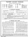
TELEVISION ALIGNMENT PROCEDURE
ALIGNMENT ADJUSTMENT IDENTIFICATION
Adj.
Al
A2
A3
A4
A5
Symbol
T303
T301
T302
L103
T201
Frequency
25.3 MC
25.3 MC
23.1 MC
23.1 MC
4.5 MC
A6
L201
4.5 MC
Function
3rd IF Transformer
1st IF Transformer
2nd IF Transformer
Mixer Plate Coil
Primary of Ratio Detector
Transformer
Sound Take-off Coil
Adj. Symbol
A7
T201
A»
A9
A1 <>
All
A12
Frequency
4.5 MC
C102
C104
C107
C110
L102
Function
Secondary of Ratio Detector
Transformer
Trimmer (RF Amplifier)
Trimmer (RF Amplifier)
Trimmer (Mixer)
Trimmer (HF Oscillator)
Slug, HF Oscillator Coils
IF A M P L I F I E R A L I G N M E N T
a. Before starting alignment, be sure IF cover shield
is mounted to chassis.
d. Set Picture control fully to the right (clockwise). Retain
this setting for all IF adjustments.
b. Disconnect antenna and connect a jumper across antenna
terminals.
<? '
c. Set receiver to channel 13 or other unassigned high
channel to prevent signal interference during IF alignment.
Step
Signal Gen.
Freq. (MC)
VTVM and Signal
Generator Connections
1
25.3
VTVM high side to test jack "T",
common to chassis.
2
3
23.1
Connect generator high side to 6J6
(V102) tube shield; insulate shield
from chassis. Connect common to
chassis near 6J6 tube base.
equipment to
"?'
To service TV chassis with radio disconnected, complete
the heater circuit by connecting a jumper from pin "L"
to pin "K" of socket M503. See schematic.
A l l o w aboul 15 minutes for receiver and test
warm
f.
Instructions
Use VTVM 3 volt DC scale. When
peaking, keep reducing generator
output for VTVM reading of approx. 1'volt or lea-.
Adjust
Al and A2 for maximum.
A3 and A4 for maximum.
To insure correct IF alignment, make the "IF Response Curve Check" given below, or make the "Overall RF
and IF Response Curve Check (Step 1)" given later. The overall check should be made after making all other
alignments.
IF RESPONSE CURVE CHECK
(Using sweep generator and oscilloscope with sweep input to RF Mixer V102.)
Differences in tube gain and component values affect IF response. These differences are not apparent in alignment of IFs
when using a signal generator and VTVM (single frequency
alignment) ; hence it is preferable that an IF response curve
check be made after completion of the IF amplifier alignment.
The IF response curve check can be made as indicated directly below. However, also note that a better check can be
made by feeding the sweep signal through the entire RF and
IF system as given under "Overall RF and IF Response Curve
Check (Step 1)". The overall check should be made after
making all other alignments.
a. Make all control settings and connections as given in the IF
amplifier alignment chart; see "a" through "f" above.
b. Connect oscilloscope* between point "V" and chassis ground
through a decoupling filter; see fig. 29. Keep leads away from
receiver.
c. Connect sweep generator high side to tube shield of 6J6
(V102) osc-mixer tube. Be sure to insulate tube shield from
chassis. Connect sweep generator common to chassis close to
6J6 tube base. Set sweep generator to sweep the IF band pass
(19 to 29 M C ) .
d. Loosely couple marker generator high side to the sweep generator lead connected to tube shield on tuner; common to
chassis ground.
To avoid distortion of the response curve, keep the sweep
generator and marker generator outputs at a very minimum.
Marker pips should be just kept barely visible. To minimize
distortion, set sweep generator output for VTVM reading of
approximately .5 volt DC, measured between test jack "T"
and chassis. Connecting a ll/2 volt battery (negative to. test
jack "T", positive to chassis) will allow greater signal input
w i t h o u t distorting the response curve.
e. Check curve obtained against the ideal IF response curve
shown in figure 28. Since it is not always possible to get ideal
curves, it should be noted that the height of opposite peaks
should be within 3db or 30% of each other. The dip or valley
in the center of the curve should not be greater thar 3db or
30% down from the highest peak of the curve. Check video
and sound IF carrier points by means of marker generator. It
is important that marker pips be in the proper location on the
response curve. The 25.75 MC marker, should be 6db below
the highest peak (50% point on the high frequency side of
the curve). The 22 MC marker should be at the opposite side
of the response curve, located approximately 18db (85%)
below the highest peak. The 21.25 MC marker should be
located at least 26db (95%) below the highest peak, and
may or may not be visible.
Consistent with proper band width and correct location of
markers, the response curve should preferably have maximum
amplitude, symmetry, and flat top appearance.
If the procedure given has been carefully followed and the
response curve obtained differs greatly from the curve shown in
figure 28, repeat the IF Amplifier Alignment, making sure generator frequencies are precise and adjustments are accurately
made.
* In dealing with RF and IF response curves, it is well to remember that an inverted or mirror image may result,
depending on the sweep generator and oscilloscope used. The general waveform should still be identical.
When using a wide band oscilloscope for alignment, marker pips will be more distinct if condenser from 100 to 1,000
mmfd. is connected across the oscilloscope input. Caution: Use the smallest condenser possible, since too high a
capacity will affect the shape of the response curve.
©John F. Rider
MODELS 36R37, 36Ri|.5,
36Rli6, Ch. 21B1, 21C1
ALIGNMENT HINT
After becoming familiar with alignment procedure, some servicemen simplify subsequent
alignment of sets by merely using the essential alignment data given in figures 29 and 30.
NOT IN tARir SETS
(KITHOUT TRAP L307)
2 5 . T 5 M C N»RKE8
APPROX. 3.2NC
(OX.
\C (USHER /
1Mb (15V.)' \,
/
1I
,
i '
6dk OR 50V.
».
5db KUINUII UO'A)
DIFFERENCE IN HEICHT Of PEAKS
SHOULD NOT E X C E E D 3db OR 30V,
GROUND TO CHASSIS'*
L-Jl
CHASSIS GROUND 'l|
• M E A S U R E D FRON HIGHEST PEAK
*•
DECOUPLING FILTER SHOWN IN DOTTED LINES
Figure 28. IF Response Curve.
Figure 29. Bottom View Showing Test Point "V".
V
A
t
All OVERALL OSCILLATOR ADJ.
Figure 30
A2
A4
xAI2 INDIVIDUAL CHANNEL ADJ.'
23.IMC MAX.
25.3MC MAX.
A3
Al
23.IMC MAX.
1
25.3MC MAX!
View of Chassis Showing Alignment Adjustment Locations.
4.5 MC SOUND IF ALIGNMENT
a. Disconnect antenna and Connect a wire juniper across
antenna terminals.
b. Set Picture control fully to the right (clockwise).
c. Connect signal generator high side to point "V" through
a .01 mfd. condenser.
.
d. Allow about 15 minutes for receiver and test equipment to
warm up.
Step
Signal Gen.
Freq. (MC)
VTV.M
Connections
e. Use a NON-METALLIC alignment tool. If Ratio Det.
Transformer (T201) has hollow core slugs, bottom slug adjustment A7 can be made from top of chassis, if you use
alignment tool #98A30-7 obtainable from Admiral Distributor. Bottom slug ( A 7 ) can be reached through the
hole ln the core of the u PP er slu g ( A 5 K
f. To service TV chassis with radio disconnected, complete
the heater circuit by connecting a jumper from pin "L"
to pin "K" of socket M503. See schematic.
Adjust
Instructions
Since the transmitted video and sound carriers have an accurate 4.5 MC frequency difference, a TV station
signal may be used instead of a signal generator for alignment of steps below. When using a television
signal, it may be necessary to use a higher scale on the VTVM.
IMPORTANT: When using a signal generator, be sure to check it against a crystal calibrator or other frequency standard for accurate frequency calibration at 4.5 MC. Accuracy is required within one kilocycle.
1
2
t4.5
t4.5
To test jack "Y"
Use 3 volt DC scale on VTVM.
Keep VTVM leads well separated from signal generator and
chassis wiring.
A5 and A6 for maximum (keep
reducing generator output to
keep VTVM at approx. 1 volt).
To test jack "Z"
Use 3 volt zero center scale on
VTVM, if available. Keep VTVM
leads well separated from signal
generator and chassis wiring.
**A7 for zero on VTVM (the
correct zero point is located between a positive and a negative
maximum).
t Signal may be unmodulated or 400 cycle AM modulated.
** If A7 was far off, repeat steps 1 and 2.
RF AND MIXER ALIGNMENT
a. Disconnect 1% volt battery from test jack "T" if used
earlier. Connect a wire jumper from test jack "T" (Fig.
30) to chassis. Leave connected for all steps in this
alignment.
b. Disconnect antenna from receiver.
c. Connect sweep generator to antenna terminals. If sweep
generator does not have a built-in marker generator, loosely
couple a marker generator to the antenna terminals. To
avoid distortion of the response curve, keep sweep genStep
Marker Gen.
Freq. (MO
Sweep Gen.
Frequency
Instructions
*205.25
**209.75
Sweeping
Channel 12
Check for curve resembling RF Response Curve shown below. If necessary,
adjust A8, A9 and A10 (Figure 30) as required. Consistent with proper band
width and correct marker location, response curve should have maximum
amplitude and flat top appearance.
Check each channel operating in the service area for curve resembling RF
Response Curve shown below. When checking any channel, set the sweep
and marker generators for the proper frequencies as indicated in the table
below.
In general, the adjustment performed in step 1 is sufficient to give satisfactory
response curves on all channels. However, if reasonable alignment is not obtained on a particular channel, (a) check to see that coils have not been intermixed, or (b) try replacing the pair of coils for that particular channel, or
(c) repeat step 1 for the weak channel as a compromise adjustment to favor
this particular channel. If a compromise adjustment is made, other channels
operating in the service area should be checked to make certain that they
have not been appreciably affected.
See table below.
* Video Carrier Frequency (MC).
Channel Channel
Number Freq., MC
2
54- 60
3
60- 66
4
66- 72
5
6
7
8
9
10
11
12
13
erator output at a minimum, marker pips just barely visible.
d. Connect oscilloscope through a 10,000 ohm resistor to test
point "W" on tuner (Fig. 30). Keep scope leads away
from chassis.
e. Allow about 15 minutes for receiver and test equipment
to warm up.
f. To service TV chassis with radio disconnected, complete
the heater circuit by connecting a jumper from pin "L"
to pin "K" of socket M503. See schematic.
76- 82
82- 88
174-180
180-186
186-192
192-198
198-204
204-210
210-216
Video
Carrier,
Sound Carrier Frequency (MC).
Sound
Carrier,
MC
MC
55.25
61.25
59.75
65.75
67.25
77.25
83.25
175.25
181.25
187.25
193.25
199.25
205.25
211.25
87.75
179.75
185.75
191.75
197.75
203.75
209.75
215.75
71.75
81.75
HAfUEH, VIDEO
CARRIER
NifUER, SOUND
CARRIER
Full skirt of curve will not be visible unless
generator sweep width extends beyond 10 MC.
Figure 31. RF Response Curve (see "Oscilloscope Note" below).
6J6 TUBE SHIELD
OSCILLOSCOPE NOTE
In dealing with RF and IF response curves, it is well
to remember that an inverted or mirror image may result, depending on the sweep generator and oscilloscope
used. The general waveform should still be identical.
When using a wide band oscilloscope for alignment,
marker pips will be more distinct if condenser from 100
to 1,000 mmfd. is connected across the oscilloscope input.
Caution: Use the lowest capacity condenser possible,
since too high a capacity will affect the shape of the
response curve.
A4
AI2
INDIVIDUAL CHANNEL
SLUG A O J U S T K E N T
( T U R R E T POSITIONED TO
A D J U S T CHANNEL 6)
T U N I N G ROTOR
SHOHN
»T HALF R O T A T I O N
Fig.
©John F. Rider
FLAI O F S E L E C T O R S H A F T
F A C I N G COIL FOR C H A N N E L 3
32. Front View of Tuner.
OVERALL RF and IF RESPONSE CURVE CHECK (Step 1)
and
HF OSCILLATOR ALIGNMENT (Step 2)
(Using sweep generator and oscilloscope.)
a. Disconnect antenna.
b. Disconnect signal generator and VTVM (if used earlier).
c. Set the Tuning control at half rotation by rotating it
approximately 150° as shown in figure 32. Set Picture
control fully to the right (clockwise).
d. Connect sweep generator to antenna terminals. If sweep
generator does not have a built-in marker generator, loosely
couple a marker generator to the antenna terminals. To
avoid distortion of the response curve, keep sweep generator output at a minimum, marker pips just barely
visible. Connecting a 1% volt battery (negative to test
Step
Marker Gen.
Freq. (MC)
Sweep Gen.
Frequency
e.
f.
g.
h.
jack "T"; positive to chassis) will allow greater signal
input without distorting response curve.
Connect oscilloscope between point "V" and chassis ground
through a decoupling filter (see figure 29). Keep oscilloscope leads away from chassis.
Allow about 15 minutes for receiver and test equipment to
warm up.
When adjusting A12, use a NON-METALLIC alignment
screwdriver with a % inch blade.
To service TV chassis with radio disconnected, complete
the heater circuit by connecting a jumper from pin "L" to
pin "K" of Socket M503. See Schematic.
Instructions
While sweeping the RF band pass (channel 13 or other unassigned high channel), check the overall response
curve obtained against the ideal curve shown below. If shape of curve is not within limits shown, it will be
necessary to repeat the IF Amplifier Alignment. The IFs must be accurately aligned before correct oscillator adjustment can be made.
See channel frequency table on
previous page.
Check need for oscillator alignment by comparing the response curve obtained (for each channel operating in the service area) with the "Overall
RF and IF Response Curve" shown below. With correct oscillator alignment,
the video and sound markers should locate at the points shown on the response curve. The Tuning control must be at half rotation (see figure 32)
when making this check.
If a major number of channels are far off in the same direction, make the
overall oscillator adjustment All. (Touch-up of individual channel slugs A12
may also be required.)
If only individual channel adjustment is required, adjust the proper channel
slug A12.
Make all oscillator adjustments so that the video and sound marker pips appear at the proper points on the response curve. Important: Before making
oscillator adjustments, be sure that the Tuning control is set at half rotation;
see figure 32. Only slight rotation of the slug (A12) will be required; turning
the slug in too far will cause the slug to fall into the coil. (If an oscillator
slug should fall into a coil, remove the coil, move the slug retaining spring
aside, lightly tap the open end of the coil against a solid object until the slug
slips out. Replace slug and set the slug retaining spring into its cut-out slot.)
Fig. 33. Overall RF and
IF Response Curve.
DIFFERENCE IN NEICHT OF P E A K S
SHOULD DOT EXCEED 3Jb OR 30V.
i MEASURED FROM HICHEST PEAK
SERVICING RADIO SEPARATELY
The radio receives its operating
voltages from the power supply on
OA
the TV chassis. It is necessary to
• N5>
*M •
•
use a separate power supply if the
P /
\
«
radio is to be operated without the
TV chassis. The 2PA1 power sup3000JL.5HATT
ply, which is used in radio-phonotelevision combination sets with the 20Z1 (12" picture)
television chassis and 5B2 radio, can be used to operate
the 5D2 radio if a 3,000 ohm, 5 watt resistor (part number 61A1-15) is connected between pins M and N of the
2PA1 socket as illustrated.
«
5D2 RADIO PRODUCTION CHANGE
To improve sensitivity of the 5D2 radio, the 1st IF
transformers in the AM and FM stages were changed.
The 1st AM-IF transformer (T604) used in early
sets, part 72B97 has been replaced with part 72B97-1.
The 1st FM-IF transformer (T601) used in early
sets, part 72B98 has been replaced with part 72B98-1.
To accommodate this change of the IF transformers,
C608 has been changed from 40 mmfd (part 65B1-65) to
30 mmfd (part 65B1-69); R602 has been changed from
240 ohms, 5%, 1/2 watt (part 60B7-241) to 1,500 ohms,
1/2 watt (part 60B8-152).
IMPORTANT: All changes mentioned above must be
made when replacing early IF transformers with late
IF transformers.
_ „_
_A_n_
-lA-nl r1
MODELS 3oR37> 3oR45
36R1+6, Ch. 21B1, 21C1
Form No. S336(1) Additions to the preliminary service data already published on 21B1, 21C1, 5D2 chassis.
(2) Circuit information on 21D1, 21H1, 21J1 television chassis and 3C1 radio chassis.
(3) Revised instructions on Horizontal Drive and Horizontal Linearity adjustments.
(4) Cabinet parts for models 16R12, 26R12, 26X55A to 26X75A, 26R25A to 26R37A, and 39X35, 39X36.
21D1, 21H1 and 21J1 CHASSIS
The 21B1 and 21C1 chassis use a 16" rectangular picture tube. The 21D1 chassis use a 16" round picture tube. The 21H1 and 21J1 chassis use a 19" round picture tube, which is mounted separately from the
chassis.
The 21B1, 21C1 chassis (16" rectangular tube) and the 21H1, 21J1 chassis (19" round tube) are the same
electrically except for some differences in the deflection yoke. See the schematic and the schematic inset
(for the deflection circuit used in 19" sets).
The 21D1 (16" round) chassis differs in that the vertical and horizontal output circuits have differences
in some component values, in the tube complement, and in B+ distribution. The vertical output tube is a
6W6GT in the 21D1 chassis; the horizontal output tube is a 6CD6GT. Since there are differences in the
horizontal output circuit of the 16" round sets, adjustment of the horizontal drive will be different. Seethe
discussion on the following pages.
3C1 RADIO (AM ONLY)
Combination models 39X35, 39X36 use the 3C1 radio (AM only). See schematic. The radio receives its
operating voltage from the TV chassis. The radio can be operated separately from the television chassis
by using the 2PA1 power supply as instructed in "Preliminary Service Data", Form No. S336-1.
PRODUCTION CHANGES AND SERVICE
NOTES
RUN 4 in 21C1 CHASSIS and RUN 1 in 21B1 CHASSIS
Adjacent Lower Channel Sound Trap (L307 and C314) Added. Later production sets have an Adjacent Lower
Channel Sound Trap added between the connector lug (terminal of C113) on the TV tuner and pin 1 of this 1st
IF amplifier tube V301 (6AU6). The trap (part number 72A102), consisting of L307 and C314, is pre-tuned
at 27. 25 MC.
This trap will eliminate the herringbone interference pattern produced by the sound carrier of the adjacent lower channel. Close examination of this type of interference will reveal that the fine lines of the herringbone pattern will vary in accordance with the speech or music on the adjacent lower channel.
Since FM interference from other sources will also produce a herringbone pattern, the presence oi interference from a station on the adjacent lower channel should be definitely determined before deciding that the
trap is required. This can be checked by quickly turning the channel selector to the adjacent lower channel.
After installing the trap, realign slug A4 (mixer plate coil L105) as instructed under "IF Amplifier Alignment" in Preliminary Service Data, Form No. S336-1.
All 21D1, 21H1, 21 Jl chassis have this trap.
RUN 5 in 21C1 CHASSIS and RUN 2 in 21B1 CHASSIS
Noise Filter Added to Improve Sync Immunity to Noise. In areas where the noise level is high, noise peaks
may affect the horizontal or vertical sync and cause the picture to shake horizontally or lose horizontal or
vertical sync. A change in value of resistor R323 and an additional filter (R329 and C315) have been incorporated in the sync circuit of later production chassis to reduce this trouble. See schematic.
This circuit change began with run 2 of 21B1 chassis and run 5 of 21C1 chassis; all 21D1, 21H1, 21J1
chassis will have this sync circuit. Early production receivers may be modified by following the procedure
given below:
1. Locate the 9 lug terminal strip adjacent to vertical output transformer T402.
John F. Rider
MOD2LS 16R12, 26R12,-25A,-26A,-35A,~3oA,
-37A, 26x55A,~56A,-65A,-66A,-67A,-75A,
-76A, 39X35,"36, Ch. 21B1,-C1,-D1,-H1,-J1
2. Remove resistor R323 (8200 ohms) from between lugs 4 and 6, counting 1 from end of strip near T402.
3. Connect a 18, 000 ohms, | watt resistor (part number 60B8-183) between lugs 5 and 6.
4. Between lugs 4 and 5, connect a 150 mmfd. mica condenser (part number 65B21-151) with a 270, 000 ohm,
| watt resistor (part number 60B8-274) in parallel.
RUN 2 in 21D1 CHASSIS - CHANGE in 21J1 CHASSIS
In some 21D1 and 21J1 chassis, condenser C433 was changed from . 002 mfd, to . 0047 mfd, 600 volts
(part number 64B9-15). Some sets having this change use a single . 0047 mfd. condenser; other sets use
two . 002 mfd. condenser in parallel. This change was made to increase sweep width. Condenser C433
is . 002 mfd, in later sets using an improved horizontal output transformer.
R411 in 21D1 CHASSIS CHANGED to INCREASE RANGE of VERTICAL LINEARITY CONTROL (R410)
Resistor R411 was changed from 820 ohms, 1 watt to 680 ohms, 1 watt (part number 60B14-681). This
change was made to increase the range of the VERT. LIN. control R410.
ALTERNATE VERTICAL OUTPUT TUBE (V402) in 21B1, 21C1, 21H1, and 21J1 CHASSIS
Some sets with 16" rectangular or 19" round picture tube may use a 6SN7GT tube as an alternate
for the 6S4 vertical output tube (V402). The schematic shows the circuit used with the 6S4 tube; the
schematic inset shows the circuit used with the 6SN7GT tube.
ALTERNATE IF TUBE (V301, V302, V303)
Some sets may use a 6AG5 tube as an alternate for the 6AU6 tube in the 3rd IF stage (V303); other sets
may use a 6AG5 tube for the 1st, 2nd and 3rd IF stages (V301, V302 and V303). When the 6AG5 tube is used,
tube socket terminal 2 is unused (not grounded) as pins 2 and 7 of this tube are connected internally. A
tube shield is used in the 1st and 3rd IF stages with the 6AG5 tube.
ALTERNATE TUBE USED IN 3C1 RADIO
Early sets used a 6AV6 tube for V703 (Det-AVC-AF). A few of these early sets used the 6AT6 tube.
Later production sets use the 6SQ7 tube, which is the metal tube equivalent.
ALTERNATE CONTROL ESCUTCHEONS
Two alternate control escutcheons are used with these sets. Although the escutcheons are interchangeable as a complete unit, individual parts for the two alternate escutcheons are not interchangeable. The
different escutcheons can be identified by the type of door spring used and the differences in the cutout slot
which supports the ends of the door springs.
The parts for the control escutcheon having an "I" shaped slot using a flat (bronze) door spring are:
Escutcheon, Control (less door). . . . . .23D 60-3
Escutcheon Door
.23D 60-2
Escutcheon Door Spring, Flat (bronze). .18A 41
The parts for the control escutcheon having a "U" shaped slot using a coil (wire) door spring are:
Escutcheon, Control (less door)
23D 60-6
Escutcheon Door.
23D 60-7
Escutcheon Door Spring, Coil (wire)
right side (facing front)
19A 65-1
left side (facing front).
19A 65-2
REPAIRING MOUNTING LUGS on PICTURE WINDOW
If only the mounting lugs are broken on picture windows 23D67, 23E62-1, and 23D61-1, a metal replacement lug can be pressed into the plastic by heating it with a soldering iron. Instructions for installing
(Form No. S340) are included with the 3 lugs supplied under part number 15A668.
H
SERVICE
ADJUSTMENTS
The following information on making the Horizontal Drive and Horizontal Linearity adjustment corrects
and supercedes the information given in "Installation and Service Notes for 21B1, 21C1 Chassis", Form
No. 41A9-13.
HORIZONTAL DRIVE and HORIZONTAL LINEARITY ADJUSTMENT for 21B1, 21C1, 21H1, 21J1 CHASSIS
If the large circle in the center of the test pattern has a cramped or flattened appearance at one side
(non-linear horizontally), turn the HOR. DRTVE adjustment screw in fully (to the right), then slowly turn
it out while adjusting for best linearity (circular shape). Note that the Horizontal Drive control also
affects width and brightness.
If horizontal no"n-linearity can not be completely corrected with the HOR. DRIVE adjustment, further
correction can be made by adjusting the HOR. LIN. control. Alternate adjustment of the Horizontal
Drive and Horizontal Linearity controls may be necessary to obtain best linearity.
HORIZONTAL DRIVE ADJUSTMENT for 21D1 CHASSIS
This adjustment should be made so that the adjustment screw is as far out (to the left) as possible
without producing vertical lines in the picture. Adjust as follows:
a. Turn the CHANNEL control to an unused channel.
b. Set BRIGHTNESS control at a lower than average setting.
c. Turn the HORIZONTAL control (front panel) completely to the left. (If the Horizontal control is not
set at the extreme left position, the vertical lines may be removed in step "d", but may re-appear
when the Horizontal control is rotated to the right.)
d. Turn the HORIZ. DRIVE adjustment screw to the left until a vertical line appear near the center of the
raster. Then, turn the screw to the right just far enough to make the lines disappear. If the screw is
turned further than required to eliminate the vertical lines, picture width and brightness may be affected.
Do not use the Horizontal Drive to correct width or linearity. If necessary, make the Width and Horizontal Linearity adjustments.
HORIZONTAL LINEARITY ADJUSTMENT for 21D1 CHASSIS
If the large circle in the center of the test pattern has a cramped or flattened appearance at either
side (non-linear horizontally), adjust the HORIZ. LIN. adjustment screw by turning it to the left or right
as required. Note that the Horizontal Drive and the Width adjustments also affect linearity. Be sure
that these adjustments are set correctly if difficulty is encountered when making the horizontal linearity
adjustment.
If vertical lines appear in the center of the picture when making the horizontal linearity adjustment,
see "Horizontal Drive Adjustment for 21D1 Chassis" above.
Form No. S336-3
C433 INCREASED to OBTAIN SUFFICIENT WIDTH
To obtain sufficient width, C433 may be .0047 mfd, 600 V. (part number 64B8-15) in some 21D1, 21H1,
2IJ1 chassis. Also, some of the 21D1 chassis may use a .01 mfd, 600 V. condenser, part number 64B8-13.
GRID RESISTOR REQUIRED WHEN V303 is 6AG5
When a 6AG5 is used at V303, an 18, 000 ohms, \t resistor (part number 60B8-183) is required from
grid (pin 1) to ground.
fi £Qy
6SN7GT
V£UJ
DIFFERENT TUBE USED for SOUND AMPLIFIER (V203)
Some sets may use a 6SQ7 tube instead of a 6AV6 tube at
V203. There are no part changes necessary with this substitution. The pin numbering for the 6SQ7 is shown in the
adjacent illustration.
•John F. Rider
V403
MFFERENT TUBE USED for SYNC SEP. and CLIPPER (V403)
Some sets may use a 6SN7GT tube instead of a 12AU7 tube
.t V403. There are no part changes necessary with this sub;titution. The pin numbering for the 6SN7GT is shown in the
idjacent illustration.
ALTERNATE CIRCUIT WHEN V402 is 6SN7GT
The schematic (in Form No. S336-2) for the
!1B1, 21C1, 21H1, 21J1 television chassis
ihows an alternate circuit for V402 when a
iSN7GT tube is used in place of the 6S4. (See
nset in lower left portion of schematic.)
ALTERNATE CIRCUIT WHEN
V402 IS 6SN7GT
1/26SN7GT
T401
VERT. OSC,
V401A
6SN7GT
VERT. OUTPUT
TO T 4 0 2
Cross out this schematic inset and in its
)lace use the circuit given in the adjacent
llustration.
R404 1.5 megohms, \
R406 2.5 megohms, f w
60B 8-155
60B 8-255
RESISTOR ADDED in VERTICAL OSCILLATOR STAGE.
VERT. HOLD
R405
1MEG
In sets using a 6S4 or a 6W6GT tube in the vertical output stage (V402), a 150, 000 ohms, 1/2 watt reiistor (part number 60B8-154) is connected between R404 and the grid (pin 1) of the vertical oscillator
V401A, 6SN7GT). This resistor centers the operating point of the Vertical Hold control.
Add this resistor to both schematics. This resistor has been used since the beginning of production.
SUPPLEMENTARY
PARTS LIST
This parts list contains corrections and additions to the parts list given in "Preliminary Service
Data for models using 21B1, 21C1, 5D2 Chassis" (Form No. S336-1). Use this parts list FIRST, then
use the list in the Preliminary Service Data.
RESISTORS
Sym.
5 R401
SR402
SR403
R406
R407
K40D
Description
22, 000 ohms, j w a t t
8, 200 ohms, '2 watt
8, 200 ohms, }, watt
1 megohm, '2 watt, in sets using 6S4
vert, output tube (V402)
1. 5 megohm, 5 watt, in sets u s i n g
6SN7GT vert, output tube (V402). .
680, 000 ohms, j w a t t , in sets using
6W6GT vert, output tube (V402). , .
8, 200 ohms, 5 watt
In 21B1, 21C1, 21H1, 21J1
10, 000 ohms, j watt, in 21D1
1 megohm, 2 watt, in 21B1, 21C1,
21H1, 21J1
3. 3 megohms. I w a t t , in 21D1. 21L1. .
Par t No.
60B 8-223
60B 8-822
60B 8-822
60B
8-105
60B
8-155
60B 8-684
60B
60B
60B 8-105
GOB 8-335
[3, 000 ohms. Vert. Lin.
\r 21B1, i l C l , 21H1, 21J1
75B 13-7
I for 21D1. 21E1
.75B 13-18
820 ohms, i w a t t , in sets using 6S4
vert, output tube (V40J)
BOB 8-821
R411 680 ohms, | w a t t , in sets using
6SN7GT vert, output tube (V402). . . 60B 8-681
680 ohms, 1 w a t t , in sets using
6W6GT vert, output tube (V402)
60B 14-821
(R411 was 820 ohms in early (21D1) sets using
6W6GT tube, see production changes.)
[820 ohms, 2 watt,
R415 < in 21B1, 21C1, 21H1, 21J1
60B 20-811
1.2, 200 ohms, { watt, in 21D1, 21E1. . . . 60B 8-222
(8, 200 ohms, 1 watt,
R435 \n 21B1, 21C1, 21H1, 21J1
60B 14-822
[12, 000 ohms. 1 watt, in 21D1. 21E1. . . 60B 14-123
R619A 2 megohms, Volume]
R619B 2 megohms, Tone /P o t
75B U - 12
(R619 includes on-off switch SW603)
R410
{
tPart of Diode Filter Unit-63A3-l consisting of R707, C709, C710.
§ Component may be part of coupiate, part number 63B6-2. Order exact duplicate or individual components.
MODELS 16R12, 26R12,-25A,-26A,-3^A,-36A,
-37A, 26x55A,-56A,-65A,-66A,-6?A,-75A,
-?6A, 39X35,-36, Ch. 21B1,-C1,-D1,-H1,-J1
R701
R702
R703
R704
R705
R706
tR707
R708
R709
22,000 ohms, 1/2 watt
10,000 ohms, 1 watt
150 ohms, 1/2 watt
27,000 ohms, 1 watt
2,200 ohms, 2 watt
1 megohm, 1/2 watt...
47,000 ohms, 1/2 watt
4.7 megohms, 1/2 watt
27,000 ohms, 1/2 watt
R710A 2 megohms, Tone 1
R710B 2 megohms, Volume/
(includes SW702)
R711 22 ohms, 5 watt
60B 8-223
GOB 14-103
60B 8-151
. . . 6 0 B 14-273
60B 20-222
60B 8-105
.
75B 11-12
60B 8-220
Sym.
Description
Part No.
. 002 mfd, 600 volts, paper
64B 5-14
. 005 mfd, 600 volts, paper
64B 5-12
. 0047 mfd, mica
65B 21-472
470 mmfd, mica
C421
in 21B1, 21C1, 21H1, 21J1
65B 21-471
330 mmfd, mica, in 21D1
65B 21-331
'47 mmfd, 5%, 1, 500 volts, mica,
in 16" sets
65B 1-64
75 mmfd, 5%, 1, 500 volts, mica,
in 19" sets
65B 1-66
.002 mfd, 600 volts, paper
64B 9-11
(.0047 mfd. used in some 21D1 and
21J1 chassis, see production changes)
65B 1-62
C701 5 mmfd, mica
„
66B 8-5
C702 2 to 20 mmfd, trimmer
.
C703A 0 to 420 mmfd.l
68B 32
C703B 0 to 108 mmfd) ^ng
(Note: Dial drum spot-welded to gang.)
C704 50 mmfd, ceramic
65B 6-4
C705 .005 mfd. min, ceramic
65A 10-1
C706 .1 mfd, 200 volts, paper
64B 5-30
C707 .005 mfd. min, ceramic
65A 10-1
C708 .1 mfd, 400 volts, paper
64B 5-20
tC709 100 mmfd, ceramic
tC710 100 mmfd, ceramic
. 64B 5-25
C711 .01 mfd, 400 volts, paper...
65B 6-5
C712 250 mmfd, ceramic
64B 5-25
C713 .01 mfd, 400 volts, paper.
. 64B 5-14
C714 .002 mfd, 600 volts, paper.
SC401
SC402
SC403
COILS and TRANSFORMERS
L701
L702
T202
T402
T403
T404
T701
T702
Description
Part No.
Focus Coil
f o r 2 1 B l , 21C1, 21H1, 21J1
69C 117-3
for 21D1, 21E1 (suppliedless plug). 69C 117-4
AM Antenna
Loop Antgnna (includes C701, C702). 69C 116-2
Iron Core Ant. (includes C701, C702) 69C 121-2
Oscillator Coil
69A 52-1
Audio Output Transformer
for TV only sets
79C 33-1
for combination sets
79C 33-2
Vertical Output Transformer
79B 29-1
for 21B1, 21C1, 21H1, 21J1
for 21D1, 21E1
79B 34-1
Deflection Yoke
(includes R412, R413, R445, C430)
for 16" rectangular tube
A3222
for 16" round tube
A3178
for 19" round tube
A3197
(A3197 includes connector plug)
Horizontal Output Transformer
(includes tube cap clips)
for 21B1, 21C1, 21H1, 21J1
. 79C 30-2
for 21D1, 21E1
.79C 30-3
1st IF Transformer
72B 28-7
2nd IF Transformer.
72B 28-17
©John I. Rider
Sym.
M203
60B 8-475
60B 8-273
CONDENSERS
Sym.
L404
MISCELLANEOUS PARTS for TV CHASSIS
Picture tube mounting parts listed below are for 16"
tubes. See separate heading for 19" tube mounting parts.
Description
Speaker
5" PM
8" PM
10" PM
12" PM
Part No.
78B 59-1
78B 49-1
78B 47-2
.788 56-2
Socket, Focus Coil (5 contact wafer). .87A 4-4
Plug, Focus Coil (5 pin)
.88A 3-5
Cover & Insulator (for 88A3-5 plug). . .88A 3-4
M405 Socket, Deflection Yoke
(6 contact, molded)
87A 30-2
M406 Plug, Deflection Yoke (6 pin)
88A 9-1
Cover & Insulator (for 88;i9-l plug).. 88A 17
M504 Socket, Light (4 contact, wafer; used
only in 19" combination sets)
87A 6-3
Band, Metal Tube (for mtg. 16" round tube). .28A 40-1
Band, Plastic Insulating (for mounting
J3A 59-1
16" round tube)
,
Bracket, Picture Tube Mounting (supports
front of rectangular picture tube)
,15B 615-1
Right side (facing tube)
Left side (facing tube)
.15B 615-2
Bracket, Picture Tube Mounting (supports
front of 16" round tube)
,
15C 576
Bracket, Top and Bottom (for mounting
picture tube and focus coil)
for rectangular picture tubes
Top
15C 613
Bottom
15C 614
for 16" round tubes
15C 628-1
Top
Bottom
15C 627
Clamp, Picture Tube Front Mtg. Bracket
(for mtg. rectangular picture tube)
ISA 616
Clamp, Webbing (for mtg. rectangular tube). 15A 526
Clip, Tube Cap
for 6CD6G tube.
88A 16-6
for 6BQ6GT tube
88A 16-8
for 1B3GT tube
. . . . . . . . . . . . . . 19A 54
Connector Lead, 2nd Anode
with plug for 16" rectangular tube
88A 16-7
with contact spring for 16" round tube
A3171
with female plug for 19" round t u b e . . . . . . . 88A 25-1
with male plug and contact spring for
19" round tube.
A3200
Ion Trap
for round picture tubes
94A 15-2
94A 15-1
for rectangular picture tubes
2A 1-15-71
Nut, Tube Band Mounting (8-32)
Pilot Light (#47)
81A 1-8
Rubber Channel, 1" long (for rectangular
12A 9-11
picture tube bracket)
Rubber Insert, 1" diameter (bottom and side
12A 16-1
support of rectangular picture tube)
12A 1-15
Rubber Grommet (for 2nd anode load)
1A 101-1-71
Screw, Wing (for deflection yoke)
87A 7-7
Shield, Tube
87A 7-6
Shield Base, Tube
Socket, Tube
miniature bakelite (7 pin)
87A 3-7
octal, plain
87A 5-1
87A 20-2
octal, ringmount (mica filled)
miniature (9 pin)
87A 14-2
87B 31-8
picture tube
Spring, HV Contact (for front of
round picture tube)
18A 37
Spring, Picture lube Grounding
19A 23-2
(used on rectangular tubes only)
Spring, Support (for 2nd anode lead)
19A 66
Washer, Spring (for mounting picture
4A 5-10-71
positioning lever)
Webbing, Rectangular Picture Tube Mtg.
Strap (42" length)
50A 3-4
M403
M404
PARTS for MOUNTING 19" PICTURE TUBE
Description
MODELS 16R12, 26R12, 26R25A, 26R26A,
<
26R35A, 26R36A, 26R37A, 26X55A, 26X56A, TJ
'. 26X65A, 26X66A, 26X67A, 26X75A, 26X76A, O
39X35,-36, Ch. 21B1,-C1,-D1,-H1,-J1
m
Part No.
103
104
Socket, Focus Coil (5 contact wafer). 87A 4-3
Plug, Focus Coil (5 pin)
88A 3-5
Cover & Insulator (for 88A3-5 plug).. 88A 3-4
105 Socket, Deflection Yoke (6 contact;
molded).....
87A 30-2
106 Plug, Deflection Yoke (6 pin-includes
interlock)
.88A 9-1
Cover & Insulator (for 88A9-1 plug).. 88A 17
ind, Tube Front Insulating (Plastic)
33B 59-2
md, Tube Retaining ( M e t a l ) . . . . . . . . . . . . . . . 2 8 A 40-2
acket, Strap (supports yoke c o i l ) . . . . . . . . . 15A 572
•acket, Tube Mtg. (supports front of tube)
for right side facing tube.
.15C 564-1
for left side facing tube
15C 564-2
'acket, Yoke (upper mtg. bracket)
.15C 628-2
'acket, Yoke Base (lower s u p p o r t ) . . . . . . . . . 15C 627
mnector Lead, 2nd Anode
with female plug.
... .88A 25-1
with male plug and contact spring
A3 200
aund Wire Assembly
A3209
Trap.
94A 15-2
yer, Picture Positioning
.15B 574
t (8-32 Hex, for tube band)
.2A 1-15-71
:ture Tube 19" T V . . . . . . „
19AP4
bber Collar (supports flare of picture tube) 12B 40
•ew, Wing (for deflection yoke)
1A 101-1-71
m, Focus Coil Mounting
32A 134
icer Sleeve (1/8" in length)
29A 2-3-71
•ing, HV Contact at front of tube
18A 37
pe, Aluminum Foil (order length needed). . 52A 1-17
.sher, Spring (for mtg 0 picture
jositioning lever)
4A 5-10-71
MISCELLANEOUS PARTS for 3C1 RADIO
'701
'702
'01
'06
'07
'08
Switch, Radio-Phono
77A 28-2
Switch, On-Off.
Part of R710
Socket, Phono Input.
88A 1
Socket, Phono Motor
89A 6-1
Shielded Cable Assembly.
89A 29-11
Plug, Cable Connector (14 pin reel.)
88A 20-1
Cover and Insulator (for plug 88A20-1). . 88A 20-6
Cable (12 wire), including 88A20-1
plug and 88A20-6 cover.
AB216
acket, Mounting
or Off-Volume and Tone control
ISA 409
or Radio-Phono Switch
.ISA 385
or Tuning Sleeve
ISA 394
p, IF Transformer Mtg
72B 28-10
ver Assembly, Chassis
A1880
il Back and Bracket Assembly
A1881
il Cord (50" length needed)
50A 1-3
il Scale
22B 23-1
cutcheon, Radio.
23D 63-3
ommet, Gang Mounting.
12A 1-2
x Nut, Switch Retaining
2A 2-11-71
ob, 'Radio-Phono', 'Tuning'
...33D55-1
ob, 'Tone'
33D 55-4
ob, 'Volume'
.33D 55-5
ckwasher, Osc. Coil & Gang (#6 I . T . ) . .
3B 1-25-71
ot Light, #47 Mazda
81A 1-8
inter, Dial.
25A 38
ift, Tuning
28A 48-1
ip Button (for mtg. dial scale)
13A 1-1-71
:ket, Tube
1 pin (for 6BA6, 6AV6)
87A 3-7
r pin (for 6BE6)
87A 24-3
:ket, Pilot Light (includes 14" lead)
82A 2-3
:ket, Pilot Light (includes 9" lead)
82A 2-9
icer Sleeve (for gang mounting)
29A 2-1-71
icer Sleeve (3 1/4" long, for mounting
)hono-radio switch)
29A 3-15
•ing, Dial Cord Tension
19B 1-3
sher, Vellutex (Oscillator coi1 mtg.)
5A 1-21
PARTS for PHONO COMPARTMENT LIGHT
and JEWEL LIGHT
M505
M506
Socket and Leads (miniature)
,82A 11-58
Plug (4 pin round).
88B 22-1
Cover and Insulator for 88B22-1
88B 22-3
M507 Socket and Leads (candelabra). . . . . . . .82A 12-1
SW502 Switch, Light
77A 29
Bracket, Switch
15B 502
Bulb, Light (7 watt candelabra Mazda #7C7).. . 81A 2-4
Bulb, Light (miniature #47 M a z d a ) . . . .
. . . 81A 1-8
Light Assembly, Complete (less bulbs). . . . . . AB209
Shield, Light
'.
82A 13
Washer, Insulating
5A 1-31
CABINET PARTS for 36R37 (Blond),
26R45 (Walnut), 36R46 (Mahogany)
When ordering parts for these models, use this list FIRST,
then see Form No. S338-1 for any parts not listed here.
Part No.
23D 60-1
23D 60-5
23D 60-4
23D 60-8
ISA 41
19A 65-2
19A 65-1
Description
Escutcheon, Control (less door)
with "I" shaped slot, for flat door spring
with "U" shaped slot, for coil door spring
Escutcheon, Door
used with 23D60-1 escutcheon
(mounts with flat door spring)
used with 23D60-5 escutcheon
(mounts with coil door spring)
Spring, Escutcheon Door
flat (bronze) spring, used with 23D60-1
escutcheon, for left or right hinge
coil (wire) spring, used with 23D60-5 escutcheon
for left hinge (facing front)
for right hinge (facing front)
CABINET PARTS for 16R12 (Mahogany), 26R12 (Mahogany)
Above model numbers may have the suffix "N".
Part No.
A3131
A3287
A3289
A3015
46B 26
34E 36-2
34E 37-2
44B 183
44B 187
98A 60-7
23D 60-1
23D 60-5
23D 60-4
23D 60-8
12A 32-6
36B 3-20
36B 3-44
33C 53-9
33C 53-10
33C 53-11
33C 53-12
89A 22-1
6A 4-10
Description
Antenna, Built-in TV
Back, Cabinet (includes line cord)
for table model
for console model
Baffle Board, Speaker, for table model
"
"
"
for console model
Cabinet, Plastic, 16R12 (Mahogany)
"
"
26R12 (Mahogany)
Carton and Fillers, for table model
"
"
"
for console model
Caster (for cabinet leg)
Escutcheon, Control (less door)
with "I" shaped slot, for flat door spring
with "U" shaped slot, for coil door spring
Escutcheon, Door
used with 23D 60-1 escutcheon
(mounts with flat door spring)
used with 23D 60-5 escutcheon
(mounts with coil door spring)
Gasket, Sponge Rubber (for back of pic. window)
Grille Cloth, for table model
"
"
for console model
Knob, TV, maroon, 'Channel'
"
" maroon, 'Tuning'
"
" maroon, 'Off-Volume'
"
" maroon, 'Picture'
Line Cord and Interlock Socket
Mounting Rivet, for line cord
n
i
6
D
5
85-437-C2-71 Screw, for pic. window (#8-32x7/16" BH MS)
65-375-C2-71
"
for cabinet back (#6-32x3/8" BH MS)
1A 71-3-57
"
for control escutcheon (#4x3/8" RH ST)
1A 67-44-71
"
for TV chassis (1/4-20x1 1/4")
Speaker, 5' PM, for table model
78B 59-1
PM, for console model
78B 49-1
2B 10-26-59 Speed Nut (for mtg. speaker baffle) in floor models
Spring, Escutcheon Door
18A 41
flat
(bronze) spring, used with 23D 60-1
escutcheon, for left or right hinge
coil (wire) soring, used with 23D60-5 escutcheon
19A 65-2
for left hinge (facing front)
19A 65-1
for right hinge (facing front)
ISA 43-1
Spring, TV Knob Tension, for "Tuning1 knob
ISA 43-2
"
"
"
"
for 'Off-Volume 1 knob
18A 43-3
"
"
"
"
for 'Channel' knob
5A 4-14
Washer, Felt, used behind 'Channel' knob
5A 4-15
"
" used behind 'Picture' knob
23D 68
Window, Picture
CABINET PARTS for 26X55A, 26X56A, 26X57A,
26X65A, 26X66A, 26X67A, 26X75A, 26X76A
This parts list applies only to models having the suffix
letters "A" or "AN" and does not apply to models with the
suffix "N" only or without any suffix letter.
Part No.
A3132
43D 102
43D 116
43C 101-3
A3337
35E 130-1
35E 130-2
35E 130-3
35E 131-1
35E 131-2
35E 131-3
35E 132-1
35E 132-2
35E 131-53
35E 131-54
35E 131-55
35E 132-56
35E 132-57
44B 182
44B 184
44B 185
98A 60-7
Description
Antenna, Built-in TV
Backing, Cardboard, for 23D61 picture window
"
"
for 23D61-1 picture window
Back, Lower TV Compartment
Back, Television Compartment (complete)
*Cabinet, Wood, 26X55A (Walnut)
"
"
26X56A (Mahogany)
"
"
26X57A (Blond)
26X65A (Walnut)
26X66A (Mahogany)
"
"
26X67A (Blond)
'26X75A (Walnut)
26X76A (Mahogany)
*Cabinet Legs 26X65A (Walnut)
26X66A (Mahogany)
"
26X67A (Blond)
26X75A (Walnut)
26X76A (Mahogany)
Carton and Fillers, for 26X55A, 26X56A, 26X57A
for 26X65A, 26X66A, 26X67A
for 26X75A, 26X76A
Caster, for Cabinet Leg
35E
35E
35E
35E
35E
Handle, Door
pair for 26X65A (Walnut), 26X66A (Mahog.),
26X67A (Blond)
37A 34
pair for 26X75A (Walnut), 26X76A (Mahog.)
*Hinge, Knife
35E 131-56
*pair for 26X65A (Walnut), 26X66A (Mahog.)
35E 131-57
*pair for 26X67A (Blond)
35E 132-53
*pair for 26X75A (Walnut), 26X76A (Mahog.)
33C 53-9
Knob, Television, 'Channel'
33C 53-10
"
"
'Tuning 1
33C 53-11
"
"
'Off-Volume'
33C 53-12
"
"
'Picture'
89A 22-1
Line Cord and Interlock Socket
1A 7-9-57 Screw, for control escutcheon (#4x3/6 RH WS)
1A 6-24-59
" for mtg. back & bumper strip (#6x5 RH WS)
1A 22-8-71
" for picture window (#6x| RH WS)
1A 67-43-71
" for mtg. TV chassis (i-20xl-l)
32D 127
Sheet, Insulating (mounts on cabinet in front
of picture tube)
78B 47-2
Speaker, 10" PM
Spring, Escutcheon Door
ISA 41
flat (bronze) spring, usedwith 23D60-3 escutcheon
for left or right hinge
coil (wire) spring, usedwith 23D60-6 escutcheon
19A 65-2
for left hinge (facing front)
19A 65-1
for right hinge (facing front)
18A 43-1
Spring, TV Knob Tension, for 'Tuning' knob
ISA 43-2
'
"
f o r 'Off-Volume' knob
ISA 43-3
"
"
"
»
for 'Channel 1 knob
Trim, Picture Window (Plastic; 55" long,
used with 23D61 picture window)
33A 57-1
Maroon, for Walnut, Mahogany
33A 57-4
Beige, for Blond
5A 4-14
Washer, Felt, used behind 'Channel' knob
5A 4-15
"
" used behind 'Picture' knob
Window, Picture
23D 61
with round holes, for mtg. with screws
23D 61-1
with oblong holes, for mtg. with spring clips
37A 30-1
If only the mounting lugs are broken on picture window
23D61-1, a metal replacement lug (part number 15A668)
can be pressed into the plastic by heating it with a soldering iron. Instructions for installing (Form No. S340) are
included with the 3 lugs furnished under part number
15A668.
CABINET PARTS for 39X35 (Walnut), 39X36 (Mahogany)
The above model numbers may contain the suffix "N".
A3023
43C 108-2
43C 114-2
43C 107-2
A3193
43D 105
43D 119
Antenna, Built-in "Roto-Scope" TV
Back, for Album Compartment
"
for Cabinet (below TV compartment)
" for Record Changer Compartment
" for Television Compartment (Complete)
Backing, Cardboard, for 23E 62 pic. window
"
"
for 23E 62-1 pic. window
131-50 *Doors, Matched Pair, 26X65A (Walnut)
131-51
"
"
"
26X66A (Mahogany)
131-52
"
"
"
26X67A (Blond)
132-50
"
"
"
26X75A (Walnut)
132-51
"
"
"
26X76A (Mahogany)
*Door Catch and Strike Plate
Bracket, Slide to Pan Mtg.
35E 131-58
*for 26X65A (Walnut), 26X66A (Mahogany)
15C 620-3
Left side (facing front of cabinet)
35E 131-59
*for 26X67A (Blond)
15C 620-4
Right side (facing front of cabinet)
35E 132-55
*for 26X75A (Walnut), 26X76A (Mahogany)
ISA 624
Bracket, Changer Stop
Escutcheon, Control (less door)
35E 136-1 *Cabinet, Walnut
23D 60-3
with "I" shaped slot, for flat door spring
35E 136-2
"
Mahogany
23D 60-6
with "U" shaped slot, for coil door spring
Carton and Fillers
Escutcheon, Door
98A 60-7
Caster, for cabinet leg
23D 60-2
used with 23D60-3 escutcheon (mounts
11B 12-6
Clamp, plastic, for cable
with flat door spring)
Decal, Cabinet Door Refinishing
23D 60-7
used with 23D60-6 escutcheon (mounts
35E 136-60
for pair of doors, Walnut
with coil door spring)
35E 136-61
for pair of doors, Mahogany
12A 32-6
Gasket, Sponge Rubber (40" long,
98A 11-3
Decal Cement (1 pint)
used with picture window)
35E 136-53 *Door, Record Compt. (Complete) Walnut
36A 7-11
Grille, Metal, for 26X65A (Walnut),
35E 136-54
"
"
"
(Complete) Mahog.
26X66A (Mahog.), 26X67A (Blond)
*Doors, TV and Radio-Phono Compt.,
Grille Cloth
35E 136-50
matched pair for Walnut
36B 3-49
for 26X55A (Walnut), 26X56A (Mahogany)
35E 136-51
matched pair for Mahogany
36B 3-50
for 26X57A (Blond)
36B 3-47
for 26X65A (Walnut), 26X66A (Mahogany)
35E 136-63 Door Catch and Strike Plate
36B 3-48
for 26X67A (Blond)
37A 25-2
Door Handle (for upper doors)
36B 3-41
for 26X75A (Walnut), 26X76A (Mahogany)
Escutcheon, Control (less door)
Grounding Clip (includes 30" braided wire)
with "I" shaped slot, for flat door spring
23D 60-3
for grounding 23D61 picture window
A3229
with "U" shaped slot, for coil door spring
Z3D 60-6
for grounding 23D61-1 picture window
A3232
*To insure proper matching and fit, also specify cabinet manufacturer's code letters (usually burned or stamped on the back
rail of cabinet). Wood parts are supplied only if old part cannot be repaired. When ordering describe condition of oldpartin detail.
'John 7. Rider
Escutcheon, Door
used with 23D 60-3 escutcheon (mounts
with flat door spring)
23D 60-7
used with 23D 60-6 escutcheon (mounts
with coil door spring)
23D 63-3
Escutcheon, Radio
12A 32-7
Gasket, Sponge Rubber (for picture window)
36B 3-53
Grille Cloth (2 pieces)
Grounding Clip (includes 30" braided wire)
A3229
for grounding 23D 61 picture window
A3232
for grounding 23D 61-1 picture window
35E 136-56 *Hinge, Knife (pair), for Radio and TV Compt.
35E 136-58
"
"
for Album Compt.
82A 10-8
Jewel, Pilot l i g h t (green)
33D 55-1
Knob, Radio 'Radio-Phono' ,'Tuning'
33D 55-4
"
" 'Off-Volume'
33D 55-5
"
" 'Tone'
33C 53-9
Knob, Television, for 'Channel'
33C 53-10
"
"
for 'Tuning'
33C 53-11
"
"
for 'Off-Volume'
33C 53-12
"
"
for 'Picture'
89A 22-1
L i n e Cord & fnterlock Socket
6A 4-6-0
Line Cord Mounting Rivet
81A 1-8
Pilot Light, #47
37A 31-1
Pull, Record Changer Slide
46A 4-5
Rod, Wooden Dowel (Antenna Mtg.)
1A 7-9-57
Screw, for control escutcheon (#4x3/8 RH WS)
1A 6-24-59
"
for back and bumper strip
(#6x1/2 RH WS)
1A 7-23-71
" for pic. window (#6x3/8 RH WS)
1A 67-43-71
"
for TV chassis (1/4-20x1)
361-375-C2-71 "
for mounting slide-out bracket
to slide (#6 32x3/8 FH MS)
23D 60-2
32D 128
Sheet, Insulating (mounts on cabinet in front
of picture tube)
37B 32-5
Slide and Track, Drawer
08A 4 4 - 1 7 Spacer, Fibre Cabinet Leveler (Kit of 6)
78B 56-2
Speaker, 12 inch PM
Speed Nut
2B 12-4-68
for mounting radio escutcheon
2B 10-8-59
for mounting speaker
ISA 45
Spring Clip (for mtg.23E62-l pic. window)
Spring, Escutcheon Door
18A 41
flat (bronze) spring, used with 23D60-3
escutcheon, for left or right hinge
coil (wire) spring, used with 23D60-6 escutcheon
19A 65-2
for left hinge (facing front)
19A 65-1
for right hinge (facing front)
18A 46
Spring, Slide Tension
18A 43-1
Spring, TV Knob Tension, for "Tuning1 knob
18A 43-2
"
"
"
"
for 'Off-Volume'knob
ISA 43-3
"
"
"
"
for 'Channel' knob
33A 57-2
Trim, Picture Window (used with 23E62
picture window only)
5A 4-14
Washer, Felt, used behind 'Channel' knob
5A 4-15
"
" used behind 'Picture' knob
5A 4-11
"
" used behind radio tuning knobs
Window, Picture
23E 62
with round holes, for mtg. with screws
23E 62-1
with oblong holes, for mtg. with spring clips
CABINET PARTS for 26R25A, 26R26A, 26R35A,
26R36A, 26R37A
This parts list applies only to models having the suffix
letters "A" or "AN" and does not apply to models with the
suffix "N" only or without any suffix letter.
Part No.
A3091
Description
Antenna, Built-in TV
A3337
Back, Cabinet (Complete)
35E 126-1 "Cabinet. Wood, 26R25A (Walnut)
35E 126-2
"
" 26R26A (Mahogany)
35E 125-1
"
" 26R35A (Walnut)
35E 125-2
"
" 26R36A (Mahogany)
35E 125-3
"
" 26R37A (Blond)
44B 175
Carton and Fillers, for 26R25A, 26R26A
44B 174
for 26R35A, 26R36A, 26R37A
98A 60-7
Caster, for Cabinet Leg
36E 126-50 'Doors, Matched Pair, 26H25A (Walnut)
36E 126-51
"
"
" 26R26A (Mahogany)
35E 125-50
"
"
" 26R35A (Walnut)
35E 125-51
"
"
" 26R36A (Mahogany)
35E 125-52
"
"
" 26R37A (Blond)
*Door Catch and Strike Plate
35E 126-56
for 26R25A (Walnut), 26R26A (Mahogany)
35E 125-56
for 26R35A (Walnut), 26R36A (Mahogany)
26R37A (Blond)
Escutcheon, Control (less door)
23D 60-1
with "I" shaped slot, for flat door spring
23D 60-5
with "U" shaped slot, for coil door spring
Escutcheon, Door
23D 60-4
used with 23D60-1 escutcheon
(mounts with flat door spring)
23D 60-8
used with 23D60-5 escutcheon
(mounts with coil door spring)
98A 61-8
Gasket, Sponge Rubber (includes chipboard
back for picture window)
Grille Cloth
36B 3-41
for 26R25A (Walnut), 26R26A (Mahogany)
36B 3-33
for 26R35A (Walnut), 26R36A (Mahogany)
36B 3-34
for 26R37A (Blond)
Handle, Door
37A 34
pair for 26R25A (Walnut), 26R26A (Mahogany)
37A 30
pair for 26R35A (Walnut), 26R36A (Mahogany),
26R37A (Blond)
*Hinge, Knife
35E 126-53
pair for 26R25A (Walnut), 26R26A (Mahogany)
35E 125-53
pair for 26R35A (Walnut), 26R36A (Mahogany)
35E 125-54
pair for 26R37A (Blond)
33C 53-9
Knob, Television, 'Channel'
33C 53-10
"
"
'Tuning'
33C 53-11
"
"
'Off-Volume'
33C 53-12
"
"
' Picture'
89A 22-1
Line Cord and Interlock Socket
Screw
1A 7-9-57
lor mtg. escutcheon (#4x3/8 RH WS)
1A 6-23-71
for mtg. picture window (#6x3/8 RH WS)
1A 67-43-71
for mtp. IV chassis (1-20x1)
78B 47-1
Speaker. 10" PM
Spring, Escutcheon Door
18A 41
flat (bronze) spring, used with 23D60-1
escutcheon, for left or right hinge
coil (wire) spring, used with 23D60-5 escutcheon
19A 65-2
for left hinge (facing front)
19A 65-1
for right hinge (facing front)
18A 43-1
Spring, TV Knob Tension, for 'Timing' knob
ISA 43-2
"
for 'Off-Volume' knob
18A 43-3
"
" "
"
for 'Channel' knob
18A 45
Spring Clip (for mtg. 23D67 picture window)
5A 4-14
Washer, Felt, used behind 'Channel 1 knob
5A 4-15
"
" used behind 'Picture' knob
23D 67
Window, Picture
O
55
If only the mounting lugs are broken on picture window
23D67, a metal replacement lug (part number 15A668) can
be pressed into the plastic by heating it with a soldering
iron. Instructions for installing (Form No. S340) are included with the 3 lugs supplied under part number 15A668.
O
MODELS 16R12, 26R12, 26R25A, 26R26A,
m
26R35A, 26R36A, 26R37A, 26X55A, 26X56A,
26X65A, 26X66A, 26X67A, 26X75A, 26X76A,
39X35, 39X36, Ch. 21B1, 21C1, 21D1,
21H1, 21Jl
Schematic for 21B1, 21C1, 21H1, 21J1 Televisioi
"'
\s
^ T / a i t d U L **
Y
AHTEINA
6BA6
L603
n •
6BA6
FK m. I F - » « Z « 0 . D E I .
sieoic-^
sieoii-fT
T301, T302
6AU6
i\
6AL5
R t l l O DEI
V202
IZ04
TURRET SI1TCH S E T T I N G SELECTS PUS OF
COILS LI01 I 1102 FOR CH&NNEL DESIRED.
ju n'ffff
ffJSifffff
,IA 6AG5.6BC5, OR 6CB61N
%^
«f w AA ^v°
voincfs ficfer poiir "w" tm
"rH m[S *c*mo f*°*socrf{c ic
-
,-^
Ft* ? Of 61C5 IS CONHfCW
•fW
\ \H *HUm
6AU6oR6AG5
i*!!*»l>!! !S PI* 1 t IS 10! GMJ*0[0
6AU6o«6AG5
6AU6oi6AG5
3RD IF
V303
ISl If
V30I
LIU;
.&-j
T
i?o T
4^
(iUU
.
1
\y
C109
"
I"'"
10
T
-cno
1w
M^ ".5-1
"" " C3
'^V^'
J_
L102C i >
HI02
<7I
R
f
RI03
151
"^JJ
VI02B
iruNrNc
TClll
13?
'
/£
TO HOI
VERT OUTPUT
V402
RI08
4700
•HITE
)*
CII4
It
a. ^^7 i
6SNTGT
T303
?53NC
in_
.001 "
RED
?3AJ.
1000
-CJI2A C3liJ-
^]/26SN7CT
TiXlo^-*'^
JR104
M.2MEC
IHif- 1
l«!tj
4-
10 E«D IE8NIKH
OIJMV
10
, _
",
TV"!JS!
\0 C E N T E R IESMIHL
I'" 1
Of R 4 4 6
?
1501
PRiniSr
S O C H I 1403
BOIIOH V I E W
10
PLUG
k VfE*
COIl '
4B.5AIOHI
COILS ONL»,
©John F. Rider
c<il
10
on Chassis; 5D2 radio circuit also shown.
CHASSIS 21B1, 21C1, 21H1,
21J1; Radio Ch. 5D2
6AL5
ID SI50I
- O I - O F f SIIICH
-10 PINS Of V401
FOCUS COIL AND DEFLECTION YOKE
CONNECTORS USED IN 19" SETS
/BED
'r,
,-n
C(3qJ_
, .,,.
j 1HOR. D£F.
I LVWV—{! , coil
|
1000 o! 'uAIO»|
IKI1E
,
V
7 '
brSJ
'
Schematic for 21 Dl
Televisi
6AL5
1UIIET SIIICH SETtllt SELECTS rill OF
COILS _ll«l I l»2 EDI dUMCl DESIIED.
6AG5.6BC5.0R6CB6
n*« tnmis tucn rout "w" >i[
ffJSIftfl
IIH ftlSlS fflffffff
FHOt SOCtEl
F
v,oi
HI I If till IS UHKJli
6AU6..6AG5
IITCntLU
II HI 1 til IS ItT
6AU6o.6AG5
2«0. IF
6AU6oi6AG5
Schematic for 3C1
E I I t H I H HIEHl
©John I. Rider
6BE6
ision Chassis (16"
round tube).
ncnti nit minis
run FIM rtt ami.
ISKKT mini fun mil
V306
I
Cl
L403
Radio Circuit
FIOITIril) VIEI OF PLUS «TOI:
IEII (IISIOE MISSIS) VIEI OF
S O C I E T H50S
CHASSIS 21D1;
Radio Ch. 301