1
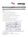
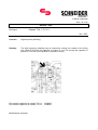
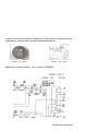
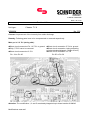
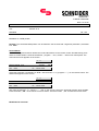
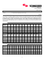
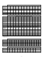
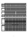
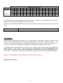
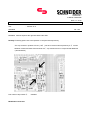
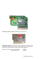
Schneider AG DUAL GmbH Silvastraße 1 D-86842 TÜRKHEIM Date : 16.03.00 Service - Info Unit : Chassis TV 9.xx No.: 245 Concern: Verticale line in the right side of the picture Remedy: To remove this problem, the soldering rivet Z 601 has to be soldered again Modifications reserved ! Schneider AG DUAL GmbH Silvastraße 1 D-86842 TÜRKHEIM Date : 16.03.00 Service - Info Unit : Chassis TV 9.xx No.: 246 Concern: Failure of the horizontal deflection Q 304 Remedy: Following parts have to be componented, controled or removed: 1.) A cap cable high voltage - transformer diode split has to be componented 2.) The software IC 902 has to be changed through the latest version 3.) A circuit connection has to be soldered in from Pin 1 / IC 701 to ground (look the sketch) 4.) A circuit connection has to be soldered in from C 704 to ground (look the sketch) 5.) The chip Z 703 has to be removed 6.) A circuit connection has to be componented like the sketch (six centimetre long) 7.) A circuit connection has to be soldered in from IC 701 / Pin 24 to Pin 25 8.) A circuit connection has to be soldered in from IC 701 / Pin 55 to Pin 56 9.) Two Diode BZT55C 5,6V have to be soldered in from IC 701 / Pin 3 and 4 to ground (anode to ground) Attention: The modification‘s was already integrated in production, therefore a modification isn‘t necessary in all cases. The changing of IC 902 is only necessary, if the Diode BZT55C wasn´t componented in pro duction. Part number cap cable high voltage: 0105922 Part number Diode BZT55C: 0100789 Part number IC 902: The IC 902 has to be ordered by means of the TV part number. Modifications reserved ! Schneider AG DUAL GmbH Silvastraße 1 D-86842 TÜRKHEIM Date : 18.12.00 Service - Info Unit type : Chassis TV9.1 / TV 9.3 No.: 252 Concern: High frequency whistling Remedy: The high frequency whistling may be caused by coming into contact of the fitting clip / diode D 305 with the capacitor in position C 314. For remedy the capacitor in position C 314 has to be replaced by a smaller version. Part number capacitor for chassis TV 9.1: Part number capacitor for chassis TV 9.3: Modifications reserved ! 0100865 0109085 Info number: 264 date: 14.09.00 Service information ! Concern: Schneider Electronics AG Silvastraße 1 86842 Türkheim / Germany Rectifier / Chassis TV 9.XX ( pos. D 102 ) for checkback:: TV-Hotline: 0049 8245-51 108 Spare part department: 0049 8245-51 71 In case of service the rectifier in position D 102 has to be replaced by the replacement version alike the below declared sketches. Rectifier „ old “ version Rectifier „ new “ version Spare part number rectifier „ new “ version : 0038833 Modification reserved! Info number: 266 date: 18.09.00 Service information ! Unit type : Chassis TV 9.xx Multipage Concern: Blocking control function by receiving low level or disturbed antenna signal Schneider Electronics AG Silvastraße 1 86842 Türkheim / Germany for checkback:: TV-Hotline: 0049 8245-51 108 Spare part department: 0049 8245-51 71 Concern : Blocking control function by receiving low level or disturbed antenna signal. Remedy : In case of service the IC in position IC 902 has to be replaced by the latest version. Attention : Due to several chassis version the IC in position IC 902 has to be ordered depending on the set identification number. Modification reserved! Schneider AG DUAL GmbH Silvastraße 1 D-86842 TÜRKHEIM Date : 20.12.99 Service - Info Unit type : Chassis TV9 no.: 226 KD0002K Concern: Black horizontal stripes Remedy: The chip-capacitors C 403 and C 404 ( 100 nF/25V ) has to be removed and replaced by a 220 nF / 50V version. Part number chip-capacitor 220 nF / 50V : 0100057 Modifications already integrated in production. Modifications reserved ! Schneider AG DUAL GmbH Silvastraße 1 D-86842 TÜRKHEIM Date : 20.12.99 Service - Info Unit type : Chassis TV9 no.: 227 KD0002K Concern: Bad vertikal synchronizing of OSD Remedy: The chip-resistor in position CR 410 has to be removed, and the chip-capacitor in position CC701 has to be altered in a 1nF version. Part number chip-capacitor 1 nF / 50V : 0100034 Attention: The modification concerning the chip-capacitors was already integrated in production, therefore a modification may be not necessary in all cases. Modifications reserved ! Schneider AG DUAL GmbH Silvastraße 1 D-86842 TÜRKHEIM Date: 20.12.99 Service - Info Unit type : Chassis TV9 No.: 235 Concern: Performance improvement concerning IC VDP 31XX (IC701) Remedy: One 10kΩ chip resistor has to be componented additional between pin 12 / IC 701 and the chip capacitor C 704 ( use the printed line to Pin 5 and Pin 1 from IC 701). Circuit diagramm / wiring side IC 701: C 704 Part number chip resistor 10 k Ω: Modifications reserved ! 0038967 PIN 12 Schneider AG DUAL GmbH Silvastraße 1 D-86842 TÜRKHEIM Date : 18.12.00 Service - Info Unit type: Chassis TV 9 KD0002K No.:236 Concern: Improvement of the immunity from static discharge. Remedy: Following parts have to be componented or removed respectively: Main p.c.b. / IC 701 (wiring side): ÅShort circuit connection Pin 1 IC 701 n ground ÇChip „Z 703“ has to be removed ÉShort circuit connection IC 701 Pin 24 n Pin 25 ÆShort circuit connection C 704 n ground ÈShort circuit connection, laying according to below declared diagram ( lenght 60 mm ) ÊShort circuit connection IC 701 Pin 55 n Pin 56 Attention: The modification 1, 2 and 5 are already integrated up to board number 0109040. Modifications reserved ! Schneider AG DUAL GmbH Silvastraße 1 D-86842 TÜRKHEIM Date : 28.12.99 Service - Info Unit : Chassis TV 9 KD0002K No.: 240 Concern: AV / RGB position Remedy: The horizontal RGB position can be altered in the servicemode / alignment parameter „Horizontal Pos. RGB“ . Service-Mode: Simultaneously press and then release the red and blue button on the remote control. Simultaneously press and then release within 5 seconds the buttons „ program + “ and „ volume - “ at the local control panel. The main service menu appears on the screen : 4 : 3 Service Mode TV 9 Version OK . . save XX TV . . leave menu Select the parameter „Horizontal Pos. RGB “ with the button 5/6( program + / - ) on the remote control. The RGB menu appears on the screen: 4 : 3 Horizontal Pos. RGB OK . . save - 10 TV . . leave menu Alter with the buttons3/4( volume + / - ) the on the remote control the horizontal position best possible. Press the button „ OK “ on the remote control to store it. Press the button „ TV “ to leave the service mode. Modifications reserved ! Schneider AG DUAL GmbH Silvastraße 1 D-86842 TÜRKHEIM Date: 17.07.00 Service-Info Concern : TV 9 NVM values depending on the set type Info 241 The chassis TV 9 exists in different versions and was used with several picture tubes. After an EEPROM swap or after a new initialisation the geometry, video and program parameter will be deleted and replaced by standard values. Therefore these parameter have to be set again. But attention, at first the set has to be set into the delivery status ( info menu / parameter „reset“ ) alike the instruction manual. After that, the below declared NVM addresses have to be observed and if necessary to be altered according the below declared table: NVM-Values for Chassis TV9.1 B/G + TV9.1 B/G-PIP Picture tube: 0059 005A 005E 0062 0E30 0E31 0E40 0E44 0066 0080 0E50 0E80 0F 00 31 17 FE 00 BC 2D 0F 69 2C 01 A59EMZ05X... 31 01 2D 17 FE 00 CA 2D 0F 69 30 01 A59ECF50X... - - - 16 2C 01 B4 64 0F 69 30 01 - - - 16 2C 01 B4 90 0F 69 2B 01 A59EMZ07X... + A59TMZ43X... A66EAK552X.. + A66EAK071X... A66EHJ43X... 0E - - 16 C8 00 D5 5F 0F 69 30 01 A63EQQ50X... - - - 16 FE 00 D1 64 0F 69 2C 01 A66EMZ43X... 0F 00 31 17 FE 00 C4 47 0F 69 2C 01 01 A66ECF50X.. - - - - 2C 01 C2 55 - - 2B 0082 0068 0069 006A 006B 0078 0200 0201 0202 0049 0E1D 00 B9 01 C5 01 6D 1D 18 15 00 04 A59EMZ05X... 00 - - - - - 1D 18 15 00 04 A59ECF50X... 00 - - - - - 1D 18 15 00 04 00 B0 01 BB 01 6D 1D 18 15 00 04 A66EHJ43X... 00 AA 01 B0 01 70 1D 18 15 00 04 A63EQQ50X... 00 A1 01 B1 01 6D 1B 16 15 00 04 A66EMZ43X... 00 B9 01 C5 01 6D 1D 18 15 00 04 A66ECF50X.. 00 B2 01 BE 01 6D 1D 18 15 00 04 A59EMZ07X... + A59TMZ43X... A66EAK552X.. + A66EAK071X... NVM-Values for Chassis TV9.1 B/G – Dolby / Part 1 Picture tube: 0059 005A 005E 0062 0E30 0E31 0E40 0E44 0066 0300 0080 0302 0E50 030E 0E80 0422 A59EMZ07X... + 0F 00 31 17 FE 00 BC 2D 0F 23 69 00 2C 1C 01 00 A59EMZ05X... 31 01 2D 17 FE 00 CA 2D 0F 23 69 00 30 1C 01 00 A59ECF50X... - - - 16 2C 01 B4 64 0F 23 69 00 30 1C 01 00 A66EAK552X.. + - - - 16 2C 01 B4 90 0F 23 69 00 2B 1C 01 00 A59TMZ43X... A66EAK071X... A66EHJ43X... 0E - - 16 C8 00 D5 5F 0F 23 69 00 30 1C 01 00 A63EQQ50X... - - - 16 FE 00 D1 64 0F 23 69 00 2C 1C 01 00 A66EMZ43X... 0F 00 31 17 FE 00 C4 47 0F 23 69 00 2C 1C 01 00 1/4 NVM-Values for Chassis TV9.1 B/G – Dolby / Part 2 Picture tube : 0082 0068 0069 006A 006B 0078 0200 0201 0202 0049 0E1D A59EMZ07X... + 00 B9 01 C5 01 6D 1D 18 15 00 04 A59EMZ05X... 00 - - - - - 1D 18 15 00 04 A59ECF50X... 00 - - - - - 1D 18 15 00 04 A66EAK552X.. + 00 B0 01 BB 01 6D 1D 18 15 00 04 A66EHJ43X... 00 AA 01 B0 01 70 1D 18 15 00 04 A63EQQ50X... 00 A1 01 B1 01 6D 1B 16 15 00 04 A66EMZ43X... 00 B9 01 C5 01 6D 1D 18 15 00 04 A59TMZ43X... A66EAK071X... NVM-Values for Chassis TV9.1 Multi / Multi-PIP / Multi-Dolby Picture tube: 0059 005A 005E 0062 0E30 0E31 0E40 0E44 0066 0080 0E20 0E50 A59EMZ07X... + 0F 00 31 17 FE 00 BC 2D 0F 69 01 2C A59EMZ05X... 31 01 2D 17 FE 00 CA 2D 0F 69 01 30 A59ECF50X... - - - 16 2C 01 B4 64 0F 69 01 30 A66EAK552X.. + - - - 16 2C 01 B4 90 0F 69 01 2B A59TMZ43X... A66EAK071X... A66EHJ43X... 0E - - 16 C8 00 D5 5F 0F 69 01 30 A63EQQ50X... - - - 16 FE 00 D1 64 0F 69 01 2C A66EMZ43X... 0F 00 31 17 FE 00 C4 47 0F 69 01 2C A66ECF50X.. - - - - 2C 01 C2 55 - - 2B 01 0C03* 0068 0069 006A 006B 0078 0200 0201 0202 0049 0E1D 2A B9 01 C5 01 6D 1D 18 15 00 04 2A - - - - - 1D 18 15 00 04 00 A59EMZ07X... + A59TMZ43X... A59EMZ05X... A59ECF50X... 2A - - - - - 1D 18 15 A66EAK552X.. + 2A B0 01 BB 01 6D 1D 18 15 04 A66EHJ43X... 2A AA 01 B0 01 70 1D 18 15 00 04 A63EQQ50X... 2A A1 01 B1 01 6D 1B 16 15 00 04 A66EMZ43X... 2A B9 01 C5 01 6D 1D 18 15 00 04 A66ECF50X.. 2A B2 01 BE 01 6D 1D 18 15 00 04 04 A66EAK071X... * ( Only for „PIP“ ) NVM-Values for Chassis TV 9.1 Nicam I Picture tube: A 66 EHJ43 X... 0049 0068 0069 006A 006B 0078 0200 0201 0202 0300 050F 0D19 0D1A 0D1C 0D02 00 AA 01 B0 01 70 1D 18 15 11 01 01 00 00 03 15 11 01 01 00 00 03 00 B2 01 BE 01 6D 1D 18 0D03 0E00 0E20 0E30 0E31 0E40 0E44 0E50 A 66 EHJ43 X... 01 11 01 C8 00 D5 7F 2B A 66 ECF50 X... 01 11 01 2C 01 C2 5F 2B 0066 0080 0E20 0E50 0059 0062 0E30 0E31 0E40 0E44 0E1E 00AB 0F 69 01 2F 0E 16 C8 00 D5 5F 01 - 0F 69 01 2F - 16 2C 01 B4 64 01 - 0F 69 01 2A - 16 C8 00 D7 54 01 CC A 66 ECF50X... NVM-Values for Chassis TV9.2 Multi Picture tube: A66EHJ43X... A66EAK552X.. + A66EAK071X... A80AEJ13X... 2/4 NVM-Values for Chassis TV9.2 Multi Dolby PIP Picture tube: A66EHJ43X... A66EAK552X.. + A66EAK071X... A80AEJ13X... 0066 0080 0300 0302 030E 0422 0E20 0E50 0059 0062 0E30 0E31 0E40 0E1E 0E44 00AB 0F 69 23 00 1C 00 01 2F 0E 16 C8 00 D5 01 5F - 0F 69 23 00 1C 00 01 2F - 16 2C 01 B4 01 64 - 0F 69 23 00 1C 00 01 2A - 16 C8 00 D7 01 54 CC 008A 0D19 0E24 0E26 0E28 0E50 0E78 0E79 0E7A 0E7B 0E7C 0E7D NVM-Values for Chassis TV9.3 B/G Picture tube: W66EHU13X... 3D 01 C3 3D 89 0E7E 0E7F 0E84 0E86 0E88 5E 01 AA 5A 88 008A 0D19 0E60 2C 26 0E8A 0E8C B0 50 0E64 0E6C 0E70 D3 56 99 B0 00 B0 00 5E 0E8E 0E8F 0E90 0E91 0E22 0E30 0E31 0E48 04 00 04 01 13 01 30 17 0E79 0E7A 0E7B 0E7C 0E7D 01 00 01 0E4A NVM-Values for Chassis TV9.3 Multi Picture tube: W66EHU13X... 0E20 0E24 0E26 0E28 0E50 0E60 0E64 0E6C 0E70 0E78 3D 01 01 C3 3D 89 2C 26 D3 56 99 B0 00 B0 00 5E 0E7E 0E7F 0E84 0E86 0E88 0E8A 0E8C 0E8E 0E8F 0E90 0E91 0E22 0E30 0E31 0E48 0E4A 5E 01 AA 5A 88 B0 50 00 04 00 04 01 12 01 30 17 NVM-Values for Chassis TV9.4 B/G Picture tube: 0049 0066 0080 005C 00AB 0200 0201 0202 0203 0E30 0E31 0E40 0E44 0E50 0E80 A51EER13X... + 00 0F 69 3C 90 1A 1A 17 17 B0 00 DF 04 31 01 0049 0059 0062 0068 0069 006A 006B A51JSY63X... NVM-Values for Chassis TV 9.6 B/G Picture tube: 00C2 00C3 0200 0201 0202 031C 0E60 0E61 A66 EHJ 43X... 00 - - 98 01 A7 01 1A 1D 1D 18 15 03 C8 00 A66 EAK 71X... 00 - - A0 01 AC 01 1A 1D 1D 18 15 03 2C 01 A66 EMZ 43X... 00 - - A0 01 AC 01 1A 1D 1D 18 15 03 FE 00 A66 ECF 50X... 00 0F 17 A0 01 AC 01 1A 1D 1D 18 15 03 FE 00 0E70 0E74 0E78 0E7A 0E80 0EBE 0EB0 0ED4 0EE1 A66 EHJ 43X... 33 60 10 33 29 04 01 64 FF 0EE2 02 A66 EAK 71X... 54 19 10 33 2B 04 01 64 FF 02 A66 EMZ 43X... 4F 51 10 33 2B 04 01 64 FF 02 A66 ECF 50X... 4F 51 10 33 2B 04 01 64 FF 02 0049 0059 0062 0068 0069 006A 006B NVM-Values for Chassis TV 9.6 Multi Picture tube: 00C2 00C3 0200 0201 0202 031C 0E60 0E61 A66 EHJ 43X... 00 - - 98 01 A7 01 1A 1D 1D 18 15 03 C8 00 A66 EAK 71X... 00 - - A0 01 AC 01 1A 1D 1D 18 15 03 2C 01 A66 EMZ 43X... 00 - - A0 01 AC 01 1A 1D 1D 18 15 03 FE 00 A66 ECF 50X... 00 0F 17 A0 01 AC 01 1A 1D 1D 18 15 03 FE 00 0E70 0E74 0E78 0E7A 0E80 0EBE 0ED4 04B7 04BA 04CE OE50 0EE1 0EE2 A66 EHJ 43X... 33 60 10 33 29 04 64 01 02 03 01 FF 02 A66 EAK 71X... 54 19 10 33 2B 04 64 01 02 03 01 FF 02 A66 EMZ 43X... 4F 51 10 33 2B 04 64 01 02 03 01 FF 02 A66 ECF 50X... 4F 51 10 33 2B 04 64 01 02 03 01 FF 02 3/4 NVM-Values for Chassis TV 9.9 Picture tube: 0049 0059 0062 0066 0068 0069 006A 006B 00A6 00C3 0200 0201 0202 031C 0E4E A66 EHJ 43X... 00 A66 EMZ 43X... 00 0E - 0F CD 01 DB 01 01 17 1D 18 15 03 01 0F 17 0F E5 01 F0 01 01 17 1D 18 15 03 01 0E60 0E70 0E74 0E80 A66 EHJ 43X... C8 D5 5F - A66 EMZ 43X... FE - 47 2C For information: If the sound disappear after the IC swap ( IC 904 ) the „new initialisation of the channel positions“ has to be taken according service manual TV 9. Additonal the NVM address 0ED2 has to be set according the following table depending on the tuner type: Set the NVM-address: 0ED2 To NVM-Data : 00 = Tuner 5002 PH5 or 01 = Tuner 6002 PH5 Service-Mode: Simultaneously press and then release the red ( picture menu ) and blue ( videotext ) button on the remote control. Simultaneously press and then release within 5 seconds the buttons „program -“ and „volume +“ at the local control panel. The NVM menu appears on the screen. Select with the buttons „n / o“ on the remote control the parameter „NVM addr.“ The NVM menu appears on the screen. The settings can be selected with the red ( picture menu ) button on the remote control and changed with buttons „volume +“ and „volume -“. Each changing of an address has to be stored separately with the button „OK“ on the remote control. After the changing of the addresses leave the service mode with the button „TV“ . To activate the modification switch off the set with the main power switch and start it again. Attention: The changing of other addresses can effect further failure! Modifications reserved ! 4/4 Schneider AG DUAL GmbH Silvastraße 1 D-86842 TÜRKHEIM Date : 21.12.99 Service - Info Unit : Chassis TV 9 KD0002K No.: 243 Concern: Vertical stripes at the right side behind the OSD Remedy: Following parts have to be replaced or componented respectively - The chip resistor in position CR 745 ( 100Ω ) has to be removed and replaced by a 0Ω version - Between emitter and basis from transistor a 0Ω chip resistor has to be componented additional ( like illustration ) Part number chip resistor 0Ω: Modification reserved ! 0100060 Schneider AG DUAL GmbH Silvastraße 1 D-86842 TÜRKHEIM Date : 11.02.00 Service - Info Unit type Concern part no. : TV 9. : Software 0101511 KD0002K No.: 251 Concern: Teletext or digital pixel on the screen. Remedy: To avoid the failure „Teletext or digital pixel on the screen “ the integrated software ( IC 902 ) has to be the version „2.AA“ or higher . Part number IC 902 ( Software ) : 0101511 Modifications reserved ! Schneider AG DUAL GmbH Silvastraße 1 D-86842 TÜRKHEIM Date: 18.12.00 Service info Unit type: Chassis TV 9.6 no.: 260 Concern: Lapsing of the 500 pages videotext memory. Remedy: To eliminate this fault the below declared „NVM address“ has to be altered in the service-mode. Service-Mode: Simultaneously press and then release the red ( picture menu ) and blue ( videotext ) button on the remote control. Simultaneously press and then release within five seconds the buttons "program -" and "volume +" at the local control panel. The main service menu appears on the screen: 4 : 3 Service Mode TV 9 Version OK . . save XX TV . . leave menu Call up with the buttons „program + / -“ on the remote control the parameter „NVM addr.“. The NVM menu appears on the screen: 4 : 3 NVM addr. 0000 OK . . save data FF TV . . leave menu The several positions of the NVM address and NVM data can be selected with the red ( picture menu ) button and changed with the buttons „volume + / -“ on the remote control . Each changing of an address has to be stored separately with the button “OK“ on the remote control. Select the following NVM address and set it according the following table: Set the NVM address 0EE2 to NVM data 02 After the changing of the address leave the service-mode with the button „TV“ on the remote control. To activate the modification switch off the TV and start it again. Attention: The changing of other addresses can effect further failure. Modifications reserved ! Schneider AG DUAL GmbH Silvastraße 1 D-86842 TÜRKHEIM Date : 20.12.99 Service - Info Unit : Chassis TV 9.4 KD0002K No.: 242 Concern: Correction operating voltage chassis TV 9.4 Attention: The chassis TV 9.4 was produced in combination with several picture tubes. Therefore the operating voltage has to be set according following information : Chassis TV 9.4 in combination with picture tube A 51 JSY 63X13 = 136V (±0,5V) Chassis TV 9.4 in combination with picture tube A 51 EER 131X78 = 130V (±0,5V) For further information see servicemanual TV 9 ! Modification reserved ! No.: 0105942 Info number: 267 date: 05.10.00 Service information ! Chassis TV 9.3 in connection with picture tube type W 66 ECK 001X13 Concern: Unsynchronizing PIP picture ( PIP-module version 3 ) Schneider Electronics AG Silvastraße 1 86842 Türkheim / Germany for checkback:: TV-Hotline: 0049 8245-51 108 Spare part department: 0049 8245-51 71 PIP-module version 1 and 2 : Modification not necessary PIP-module version 3: The Chip resistor in position R 1204 has to be removed and replaced by a 270 Ohm / 150V chip resistor. The chip diode BZT55C in position D1202 has to be componented in addition. Spare part number: Chip resistor 270 Ohm Chip diode BZT55C 0100090 0100683 Modification reserved! Schneider AG DUAL GmbH Silvastraße 1 D-86842 TÜRKHEIM Date: 05.03.99 Service info Unit type: : Chassis TV 9 / TV 9.1 / TV 9.2 / TV 9.3 KD0002K no.: 224 Concern: Neutralization of the child lock. Remedy: The child lock can be neutralized as follows: Switch to the service mode and inspect, if the parameter „KISI ruecksetzen“ is displayed on the screen. Is this parameter available, proceed like point ❷, otherwise like point ❶. Service-Mode: Simultaneously press and then release the red and blue button on the transmitter. Simultaneously press within five seconds the buttons "Programme -" and "Volume +" at the local control panel. The main service menu is displayed on the screen: 4 : 3 Service Mode TV 9 Version OK . . save XX TV . . leave menu ❶ Call up with the keys „Ö / ד, the tuning parameter „ NVM addr. “. The nvm menu is displayed on the screen: 4 : 3 NVM addr. 0000 OK . . save data FF TV . . leave menu The several positions of the nvm address and nvm data can be selected with the red button and changed with the buttons “ volume +/ -“. Each address changing has to be stored separately with the key “OK“. Select following nvm addresses and adjust them to following values: At nvm address 0D06 0D0A set the nvm data to 00 FE After the adress changing, leave service mode with the key „TV“. To save the adress changing in the eeprom, switch the television OFF and soon after ON. Attention: The changing of other addresses can effect secondary failure. ❷ Call up the tuning parameter “Kisi rücksetzen“ and set the value from “0“ to “1“. The changing has to be stored with the key “OK“. Leave service mode with the key “TV“. Modifications reserved !