1
x
DPO2000 and MSO2000 Series
Oscilloscopes
ZZZ
User Manual
*P071231900*
071-2319-00
xx
DPO2000 and MSO2000 Series
Oscilloscopes
ZZZ
User Manual
www.tektronix.com
071-2319-00
Copyright © Tektronix. All rights reserved. Licensed software products are owned by Tektronix or its subsidiaries or suppliers, and are protected by
national copyright laws and international treaty provisions.
Tektronix products are covered by U.S. and foreign patents, issued and pending. Information in this publication supersedes that in all previously
published material. Specifications and price change privileges reserved.
TEKTRONIX and TEK are registered trademarks of Tektronix, Inc.
e*Scope, OpenChoice, TekSecure, and TekVPI are registered trademarks of Tektronix, Inc.
FilterVu, and Wave Inspector are trademarks of Tektronix, Inc.
PictBridge is a registered trademark of the Standard of Camera & Imaging Products Association CIPA DC-001-2003 Digital Photo Solutions for
Imaging Devices.
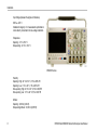
Contacting Tektronix
Tektronix, Inc.
14200 SW Karl Braun Drive
P.O. Box 500
Beaverton, OR 97077
USA
For product information, sales, service, and technical support:
In North America, call 1-800-833-9200.
Worldwide, visit www.tektronix.com to find contacts in your area.
Warranty
Tektronix warrants that the product will be free from defects in materials and workmanship for a period of three (3) years from the date of original
purchase from an authorized Tektronix distributor. If the product proves defective during this warranty period, Tektronix, at its option, either will
repair the defective product without charge for parts and labor, or will provide a replacement in exchange for the defective product. Batteries are
excluded from this warranty. Parts, modules and replacement products used by Tektronix for warranty work may be new or reconditioned to like
new performance. All replaced parts, modules and products become the property of Tektronix.
In order to obtain service under this warranty, Customer must notify Tektronix of the defect before the expiration of the warranty period and make
suitable arrangements for the performance of service. Customer shall be responsible for packaging and shipping the defective product to the service
center designated by Tektronix, shipping charges prepaid, and with a copy of customer proof of purchase. Tektronix shall pay for the return of the
product to Customer if the shipment is to a location within the country in which the Tektronix service center is located. Customer shall be responsible
for paying all shipping charges, duties, taxes, and any other charges for products returned to any other locations.
This warranty shall not apply to any defect, failure or damage caused by improper use or improper or inadequate maintenance and care. Tektronix
shall not be obligated to furnish service under this warranty a) to repair damage resulting from attempts by personnel other than Tektronix
representatives to install, repair or service the product; b) to repair damage resulting from improper use or connection to incompatible equipment; c) to
repair any damage or malfunction caused by the use of non-Tektronix supplies; or d) to service a product that has been modified or integrated with
other products when the effect of such modification or integration increases the time or difficulty of servicing the product.
THIS WARRANTY IS GIVEN BY TEKTRONIX WITH RESPECT TO THE PRODUCT IN LIEU OF ANY OTHER WARRANTIES, EXPRESS OR
IMPLIED. TEKTRONIX AND ITS VENDORS DISCLAIM ANY IMPLIED WARRANTIES OF MERCHANTABILITY OR FITNESS FOR A PARTICULAR
PURPOSE. TEKTRONIX’ RESPONSIBILITY TO REPAIR OR REPLACE DEFECTIVE PRODUCTS IS THE SOLE AND EXCLUSIVE REMEDY
PROVIDED TO THE CUSTOMER FOR BREACH OF THIS WARRANTY. TEKTRONIX AND ITS VENDORS WILL NOT BE LIABLE FOR ANY
INDIRECT, SPECIAL, INCIDENTAL, OR CONSEQUENTIAL DAMAGES IRRESPECTIVE OF WHETHER TEKTRONIX OR THE VENDOR HAS
ADVANCE NOTICE OF THE POSSIBILITY OF SUCH DAMAGES.
[W16 – 15AUG04]
Table of Contents
Table of Contents
General Safety Summary . . . . . . . . . . . . . . . . . . . . . . . . . . . . . . . . . . . . . . . . . . . . . . . . . . . . . . . . . . . . . . . . . . . . . . . . . . . . . . . . . . . . . . . . . . . . . . . . . . . . . . . . . . . . . . . . . . .
Environmental Considerations . . . . . . . . . . . . . . . . . . . . . . . . . . . . . . . . . . . . . . . . . . . . . . . . . . . . . . . . . . . . . . . . . . . . . . . . . . . . . . . . . . . . . . . . . . . . . . . . . . . . . . . . . . . .
v
viii
Preface. . . . . . . . . . . . . . . . . . . . . . . . . . . . . . . . . . . . . . . . . . . . . . . . . . . . . . . . . . . . . . . . . . . . . . . . . . . . . . . . . . . . . . . . . . . . . . . . . . . . . . . . . . . . . . . . . . . . . . . . . . . . . . . . . . . . . . . x
Key Features. . . . . . . . . . . . . . . . . . . . . . . . . . . . . . . . . . . . . . . . . . . . . . . . . . . . . . . . . . . . . . . . . . . . . . . . . . . . . . . . . . . . . . . . . . . . . . . . . . . . . . . . . . . . . . . . . . . . . . . . . . . x
Conventions Used in This Manual. . . . . . . . . . . . . . . . . . . . . . . . . . . . . . . . . . . . . . . . . . . . . . . . . . . . . . . . . . . . . . . . . . . . . . . . . . . . . . . . . . . . . . . . . . . . . . . . . . .
xii
Installation . . . . . . . . . . . . . . . . . . . . . . . . . . . . . . . . . . . . . . . . . . . . . . . . . . . . . . . . . . . . . . . . . . . . . . . . . . . . . . . . . . . . . . . . . . . . . . . . . . . . . . . . . . . . . . . . . . . . . . . . . . . . . . . . . .
Before Installation. . . . . . . . . . . . . . . . . . . . . . . . . . . . . . . . . . . . . . . . . . . . . . . . . . . . . . . . . . . . . . . . . . . . . . . . . . . . . . . . . . . . . . . . . . . . . . . . . . . . . . . . . . . . . . . . . . . . .
Operating Considerations . . . . . . . . . . . . . . . . . . . . . . . . . . . . . . . . . . . . . . . . . . . . . . . . . . . . . . . . . . . . . . . . . . . . . . . . . . . . . . . . . . . . . . . . . . . . . . . . . . . . . . . . . . . .
Connecting Probes . . . . . . . . . . . . . . . . . . . . . . . . . . . . . . . . . . . . . . . . . . . . . . . . . . . . . . . . . . . . . . . . . . . . . . . . . . . . . . . . . . . . . . . . . . . . . . . . . . . . . . . . . . . . . . . . . .
Securing the Oscilloscope . . . . . . . . . . . . . . . . . . . . . . . . . . . . . . . . . . . . . . . . . . . . . . . . . . . . . . . . . . . . . . . . . . . . . . . . . . . . . . . . . . . . . . . . . . . . . . . . . . . . . . . . . . .
Powering On the Oscilloscope . . . . . . . . . . . . . . . . . . . . . . . . . . . . . . . . . . . . . . . . . . . . . . . . . . . . . . . . . . . . . . . . . . . . . . . . . . . . . . . . . . . . . . . . . . . . . . . . . . . . . .
Powering Off the Oscilloscope . . . . . . . . . . . . . . . . . . . . . . . . . . . . . . . . . . . . . . . . . . . . . . . . . . . . . . . . . . . . . . . . . . . . . . . . . . . . . . . . . . . . . . . . . . . . . . . . . . . . . .
Functional Check . . . . . . . . . . . . . . . . . . . . . . . . . . . . . . . . . . . . . . . . . . . . . . . . . . . . . . . . . . . . . . . . . . . . . . . . . . . . . . . . . . . . . . . . . . . . . . . . . . . . . . . . . . . . . . . . . . . .
Compensating a Passive Voltage Probe . . . . . . . . . . . . . . . . . . . . . . . . . . . . . . . . . . . . . . . . . . . . . . . . . . . . . . . . . . . . . . . . . . . . . . . . . . . . . . . . . . . . . . . . . . . .
Application Module Free Trial . . . . . . . . . . . . . . . . . . . . . . . . . . . . . . . . . . . . . . . . . . . . . . . . . . . . . . . . . . . . . . . . . . . . . . . . . . . . . . . . . . . . . . . . . . . . . . . . . . . . . . .
Installing an Application Module. . . . . . . . . . . . . . . . . . . . . . . . . . . . . . . . . . . . . . . . . . . . . . . . . . . . . . . . . . . . . . . . . . . . . . . . . . . . . . . . . . . . . . . . . . . . . . . . . . . . .
Changing the User Interface Language . . . . . . . . . . . . . . . . . . . . . . . . . . . . . . . . . . . . . . . . . . . . . . . . . . . . . . . . . . . . . . . . . . . . . . . . . . . . . . . . . . . . . . . . . . . . .
Changing the Date and Time . . . . . . . . . . . . . . . . . . . . . . . . . . . . . . . . . . . . . . . . . . . . . . . . . . . . . . . . . . . . . . . . . . . . . . . . . . . . . . . . . . . . . . . . . . . . . . . . . . . . . . . .
Signal Path Compensation . . . . . . . . . . . . . . . . . . . . . . . . . . . . . . . . . . . . . . . . . . . . . . . . . . . . . . . . . . . . . . . . . . . . . . . . . . . . . . . . . . . . . . . . . . . . . . . . . . . . . . . . . .
Upgrading Firmware . . . . . . . . . . . . . . . . . . . . . . . . . . . . . . . . . . . . . . . . . . . . . . . . . . . . . . . . . . . . . . . . . . . . . . . . . . . . . . . . . . . . . . . . . . . . . . . . . . . . . . . . . . . . . . . . .
Connecting Your Oscilloscope to a Computer . . . . . . . . . . . . . . . . . . . . . . . . . . . . . . . . . . . . . . . . . . . . . . . . . . . . . . . . . . . . . . . . . . . . . . . . . . . . . . . . . . . . . .
DPO2000 and MSO2000 Series Oscilloscopes User Manual
1
1
7
12
14
15
17
18
21
23
23
24
27
29
32
39
i
Table of Contents
ii
Connecting a USB Keyboard to Your Oscilloscope . . . . . . . . . . . . . . . . . . . . . . . . . . . . . . . . . . . . . . . . . . . . . . . . . . . . . . . . . . . . . . . . . . . . . . . . . . . . . . . . .
46
Getting Acquainted with the Oscilloscope . . . . . . . . . . . . . . . . . . . . . . . . . . . . . . . . . . . . . . . . . . . . . . . . . . . . . . . . . . . . . . . . . . . . . . . . . . . . . . . . . . . . . . . . . . . . . . . .
Front-Panel Menus and Controls . . . . . . . . . . . . . . . . . . . . . . . . . . . . . . . . . . . . . . . . . . . . . . . . . . . . . . . . . . . . . . . . . . . . . . . . . . . . . . . . . . . . . . . . . . . . . . . . . . . .
Front-Panel Connectors . . . . . . . . . . . . . . . . . . . . . . . . . . . . . . . . . . . . . . . . . . . . . . . . . . . . . . . . . . . . . . . . . . . . . . . . . . . . . . . . . . . . . . . . . . . . . . . . . . . . . . . . . . . . .
Side-Panel Connector . . . . . . . . . . . . . . . . . . . . . . . . . . . . . . . . . . . . . . . . . . . . . . . . . . . . . . . . . . . . . . . . . . . . . . . . . . . . . . . . . . . . . . . . . . . . . . . . . . . . . . . . . . . . . . .
Rear-Panel Connectors. . . . . . . . . . . . . . . . . . . . . . . . . . . . . . . . . . . . . . . . . . . . . . . . . . . . . . . . . . . . . . . . . . . . . . . . . . . . . . . . . . . . . . . . . . . . . . . . . . . . . . . . . . . . . .
47
47
71
72
73
Acquire the Signal . . . . . . . . . . . . . . . . . . . . . . . . . . . . . . . . . . . . . . . . . . . . . . . . . . . . . . . . . . . . . . . . . . . . . . . . . . . . . . . . . . . . . . . . . . . . . . . . . . . . . . . . . . . . . . . . . . . . . . . . .
Setting Up Analog Channels . . . . . . . . . . . . . . . . . . . . . . . . . . . . . . . . . . . . . . . . . . . . . . . . . . . . . . . . . . . . . . . . . . . . . . . . . . . . . . . . . . . . . . . . . . . . . . . . . . . . . . . .
Using the Default Setup . . . . . . . . . . . . . . . . . . . . . . . . . . . . . . . . . . . . . . . . . . . . . . . . . . . . . . . . . . . . . . . . . . . . . . . . . . . . . . . . . . . . . . . . . . . . . . . . . . . . . . . . . . . . .
Using Autoset . . . . . . . . . . . . . . . . . . . . . . . . . . . . . . . . . . . . . . . . . . . . . . . . . . . . . . . . . . . . . . . . . . . . . . . . . . . . . . . . . . . . . . . . . . . . . . . . . . . . . . . . . . . . . . . . . . . . . . . .
Acquisition Concepts . . . . . . . . . . . . . . . . . . . . . . . . . . . . . . . . . . . . . . . . . . . . . . . . . . . . . . . . . . . . . . . . . . . . . . . . . . . . . . . . . . . . . . . . . . . . . . . . . . . . . . . . . . . . . . . .
How the Analog Acquisition Modes Work . . . . . . . . . . . . . . . . . . . . . . . . . . . . . . . . . . . . . . . . . . . . . . . . . . . . . . . . . . . . . . . . . . . . . . . . . . . . . . . . . . . . . . . . . . .
Changing the Acquisition Mode, Record Length, and Delay Time . . . . . . . . . . . . . . . . . . . . . . . . . . . . . . . . . . . . . . . . . . . . . . . . . . . . . . . . . . . . . . . . .
Using Roll Mode . . . . . . . . . . . . . . . . . . . . . . . . . . . . . . . . . . . . . . . . . . . . . . . . . . . . . . . . . . . . . . . . . . . . . . . . . . . . . . . . . . . . . . . . . . . . . . . . . . . . . . . . . . . . . . . . . . . . .
Setting Up a Serial or Parallel Bus . . . . . . . . . . . . . . . . . . . . . . . . . . . . . . . . . . . . . . . . . . . . . . . . . . . . . . . . . . . . . . . . . . . . . . . . . . . . . . . . . . . . . . . . . . . . . . . . . .
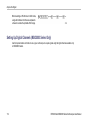
Setting Up Digital Channels (MSO2000 Series Only) . . . . . . . . . . . . . . . . . . . . . . . . . . . . . . . . . . . . . . . . . . . . . . . . . . . . . . . . . . . . . . . . . . . . . . . . . . . . .
Reducing Unwanted Noise With FilterVu. . . . . . . . . . . . . . . . . . . . . . . . . . . . . . . . . . . . . . . . . . . . . . . . . . . . . . . . . . . . . . . . . . . . . . . . . . . . . . . . . . . . . . . . . . .
Using FilterVu . . . . . . . . . . . . . . . . . . . . . . . . . . . . . . . . . . . . . . . . . . . . . . . . . . . . . . . . . . . . . . . . . . . . . . . . . . . . . . . . . . . . . . . . . . . . . . . . . . . . . . . . . . . . . . . . . . . . . . .
74
74
81
82
84
87
88
91
92
112
116
120
Trigger Setup . . . . . . . . . . . . . . . . . . . . . . . . . . . . . . . . . . . . . . . . . . . . . . . . . . . . . . . . . . . . . . . . . . . . . . . . . . . . . . . . . . . . . . . . . . . . . . . . . . . . . . . . . . . . . . . . . . . . . . . . . . . . .
Triggering Concepts . . . . . . . . . . . . . . . . . . . . . . . . . . . . . . . . . . . . . . . . . . . . . . . . . . . . . . . . . . . . . . . . . . . . . . . . . . . . . . . . . . . . . . . . . . . . . . . . . . . . . . . . . . . . . . . .
Choosing a Trigger Type. . . . . . . . . . . . . . . . . . . . . . . . . . . . . . . . . . . . . . . . . . . . . . . . . . . . . . . . . . . . . . . . . . . . . . . . . . . . . . . . . . . . . . . . . . . . . . . . . . . . . . . . . . . .
Selecting Triggers. . . . . . . . . . . . . . . . . . . . . . . . . . . . . . . . . . . . . . . . . . . . . . . . . . . . . . . . . . . . . . . . . . . . . . . . . . . . . . . . . . . . . . . . . . . . . . . . . . . . . . . . . . . . . . . . . . .
Triggering on Buses . . . . . . . . . . . . . . . . . . . . . . . . . . . . . . . . . . . . . . . . . . . . . . . . . . . . . . . . . . . . . . . . . . . . . . . . . . . . . . . . . . . . . . . . . . . . . . . . . . . . . . . . . . . . . . . .
123
123
129
130
135
DPO2000 and MSO2000 Series Oscilloscopes User Manual
Table of Contents
Checking Trigger Settings . . . . . . . . . . . . . . . . . . . . . . . . . . . . . . . . . . . . . . . . . . . . . . . . . . . . . . . . . . . . . . . . . . . . . . . . . . . . . . . . . . . . . . . . . . . . . . . . . . . . . . . . . .
Starting and Stopping an Acquisition. . . . . . . . . . . . . . . . . . . . . . . . . . . . . . . . . . . . . . . . . . . . . . . . . . . . . . . . . . . . . . . . . . . . . . . . . . . . . . . . . . . . . . . . . . . . . . .
144
145
Display Waveform Data . . . . . . . . . . . . . . . . . . . . . . . . . . . . . . . . . . . . . . . . . . . . . . . . . . . . . . . . . . . . . . . . . . . . . . . . . . . . . . . . . . . . . . . . . . . . . . . . . . . . . . . . . . . . . . . . . .
Adding and Removing a Waveform . . . . . . . . . . . . . . . . . . . . . . . . . . . . . . . . . . . . . . . . . . . . . . . . . . . . . . . . . . . . . . . . . . . . . . . . . . . . . . . . . . . . . . . . . . . . . . . .
Setting the Display Style and Persistence . . . . . . . . . . . . . . . . . . . . . . . . . . . . . . . . . . . . . . . . . . . . . . . . . . . . . . . . . . . . . . . . . . . . . . . . . . . . . . . . . . . . . . . . .
Setting Waveform Intensity . . . . . . . . . . . . . . . . . . . . . . . . . . . . . . . . . . . . . . . . . . . . . . . . . . . . . . . . . . . . . . . . . . . . . . . . . . . . . . . . . . . . . . . . . . . . . . . . . . . . . . . . .
Scaling and Positioning a Waveform . . . . . . . . . . . . . . . . . . . . . . . . . . . . . . . . . . . . . . . . . . . . . . . . . . . . . . . . . . . . . . . . . . . . . . . . . . . . . . . . . . . . . . . . . . . . . . .
Setting Input Parameters . . . . . . . . . . . . . . . . . . . . . . . . . . . . . . . . . . . . . . . . . . . . . . . . . . . . . . . . . . . . . . . . . . . . . . . . . . . . . . . . . . . . . . . . . . . . . . . . . . . . . . . . . . .
Positioning and Labeling Bus Signals . . . . . . . . . . . . . . . . . . . . . . . . . . . . . . . . . . . . . . . . . . . . . . . . . . . . . . . . . . . . . . . . . . . . . . . . . . . . . . . . . . . . . . . . . . . . . .
Positioning, Scaling, and Grouping Digital Channels . . . . . . . . . . . . . . . . . . . . . . . . . . . . . . . . . . . . . . . . . . . . . . . . . . . . . . . . . . . . . . . . . . . . . . . . . . . . . .
Viewing Digital Channels . . . . . . . . . . . . . . . . . . . . . . . . . . . . . . . . . . . . . . . . . . . . . . . . . . . . . . . . . . . . . . . . . . . . . . . . . . . . . . . . . . . . . . . . . . . . . . . . . . . . . . . . . . .
Annotating the Screen . . . . . . . . . . . . . . . . . . . . . . . . . . . . . . . . . . . . . . . . . . . . . . . . . . . . . . . . . . . . . . . . . . . . . . . . . . . . . . . . . . . . . . . . . . . . . . . . . . . . . . . . . . . . . .
146
146
147
154
155
158
162
164
169
170
Analyze Waveform Data. . . . . . . . . . . . . . . . . . . . . . . . . . . . . . . . . . . . . . . . . . . . . . . . . . . . . . . . . . . . . . . . . . . . . . . . . . . . . . . . . . . . . . . . . . . . . . . . . . . . . . . . . . . . . . . . . .
Taking Automatic Measurements. . . . . . . . . . . . . . . . . . . . . . . . . . . . . . . . . . . . . . . . . . . . . . . . . . . . . . . . . . . . . . . . . . . . . . . . . . . . . . . . . . . . . . . . . . . . . . . . . . .
Selecting Automatic Measurements. . . . . . . . . . . . . . . . . . . . . . . . . . . . . . . . . . . . . . . . . . . . . . . . . . . . . . . . . . . . . . . . . . . . . . . . . . . . . . . . . . . . . . . . . . . . . . . .
Customizing an Automatic Measurement . . . . . . . . . . . . . . . . . . . . . . . . . . . . . . . . . . . . . . . . . . . . . . . . . . . . . . . . . . . . . . . . . . . . . . . . . . . . . . . . . . . . . . . . . .
Taking Manual Measurements with Cursors . . . . . . . . . . . . . . . . . . . . . . . . . . . . . . . . . . . . . . . . . . . . . . . . . . . . . . . . . . . . . . . . . . . . . . . . . . . . . . . . . . . . . . .
Using Math Waveforms . . . . . . . . . . . . . . . . . . . . . . . . . . . . . . . . . . . . . . . . . . . . . . . . . . . . . . . . . . . . . . . . . . . . . . . . . . . . . . . . . . . . . . . . . . . . . . . . . . . . . . . . . . . . .
Using Reference Waveforms . . . . . . . . . . . . . . . . . . . . . . . . . . . . . . . . . . . . . . . . . . . . . . . . . . . . . . . . . . . . . . . . . . . . . . . . . . . . . . . . . . . . . . . . . . . . . . . . . . . . . . .
Using Wave Inspector to Manage Long Record Length Waveforms . . . . . . . . . . . . . . . . . . . . . . . . . . . . . . . . . . . . . . . . . . . . . . . . . . . . . . . . . . . . . .
172
172
174
181
187
193
196
198
Save and Recall Information . . . . . . . . . . . . . . . . . . . . . . . . . . . . . . . . . . . . . . . . . . . . . . . . . . . . . . . . . . . . . . . . . . . . . . . . . . . . . . . . . . . . . . . . . . . . . . . . . . . . . . . . . . . . .
Saving a Screen Image . . . . . . . . . . . . . . . . . . . . . . . . . . . . . . . . . . . . . . . . . . . . . . . . . . . . . . . . . . . . . . . . . . . . . . . . . . . . . . . . . . . . . . . . . . . . . . . . . . . . . . . . . . . . .
210
214
DPO2000 and MSO2000 Series Oscilloscopes User Manual
iii
Table of Contents
Saving and Recalling Waveform Data. . . . . . . . . . . . . . . . . . . . . . . . . . . . . . . . . . . . . . . . . . . . . . . . . . . . . . . . . . . . . . . . . . . . . . . . . . . . . . . . . . . . . . . . . . . . . .
Saving and Recalling Setups . . . . . . . . . . . . . . . . . . . . . . . . . . . . . . . . . . . . . . . . . . . . . . . . . . . . . . . . . . . . . . . . . . . . . . . . . . . . . . . . . . . . . . . . . . . . . . . . . . . . . . .
Saving with One Button Push . . . . . . . . . . . . . . . . . . . . . . . . . . . . . . . . . . . . . . . . . . . . . . . . . . . . . . . . . . . . . . . . . . . . . . . . . . . . . . . . . . . . . . . . . . . . . . . . . . . . . .
Saving Setup, Screen Image, and Waveform Files . . . . . . . . . . . . . . . . . . . . . . . . . . . . . . . . . . . . . . . . . . . . . . . . . . . . . . . . . . . . . . . . . . . . . . . . . . . . . . . .
Printing a Hard Copy. . . . . . . . . . . . . . . . . . . . . . . . . . . . . . . . . . . . . . . . . . . . . . . . . . . . . . . . . . . . . . . . . . . . . . . . . . . . . . . . . . . . . . . . . . . . . . . . . . . . . . . . . . . . . . . .
Erasing Oscilloscope Memory . . . . . . . . . . . . . . . . . . . . . . . . . . . . . . . . . . . . . . . . . . . . . . . . . . . . . . . . . . . . . . . . . . . . . . . . . . . . . . . . . . . . . . . . . . . . . . . . . . . . . .
216
221
224
225
227
233
Using Application Modules . . . . . . . . . . . . . . . . . . . . . . . . . . . . . . . . . . . . . . . . . . . . . . . . . . . . . . . . . . . . . . . . . . . . . . . . . . . . . . . . . . . . . . . . . . . . . . . . . . . . . . . . . . . . . . .
236
Appendix: Warranted Specifications, Safety Certifications, and Electromagnetic Compatibility . . . . . . . . . . . . . . . . . . . . . . . . . . . . . . . . . . . . . . .
237
Certifications and Compliances . . . . . . . . . . . . . . . . . . . . . . . . . . . . . . . . . . . . . . . . . . . . . . . . . . . . . . . . . . . . . . . . . . . . . . . . . . . . . . . . . . . . . . . . . . . . . . . . . . . . . . . . . .
239
Index
iv
DPO2000 and MSO2000 Series Oscilloscopes User Manual
General Safety Summary
General Safety Summary
Review the following safety precautions to avoid injury and prevent damage to this product or any products connected to it.
To avoid potential hazards, use this product only as specified.
Only qualified personnel should perform service procedures.
To Avoid Fire or Personal Injury
Use Proper Power Cord. Use only the power cord specified for this product and certified for the country of use.
Connect and Disconnect Properly. Do not connect or disconnect probes or test leads while they are connected to a voltage
source.
Connect and Disconnect Properly. De-energize the circuit under test before connecting or disconnecting the current probe.
Ground the Product. This product is grounded through the grounding conductor of the power cord. To avoid electric shock,
the grounding conductor must be connected to earth ground. Before making connections to the input or output terminals of
the product, ensure that the product is properly grounded.
Observe All Terminal Ratings. To avoid fire or shock hazard, observe all ratings and markings on the product. Consult the
product manual for further ratings information before making connections to the product.
Connect the probe reference lead to earth ground only.
Do not apply a potential to any terminal, including the common terminal, that exceeds the maximum rating of that terminal.
Power Disconnect. The power cord disconnects the product from the power source. Do not block the power cord; it must remain
accessible to the user at all times.
DPO2000 and MSO2000 Series Oscilloscopes User Manual
v
General Safety Summary
Do Not Operate Without Covers. Do not operate this product with covers or panels removed.
Do Not Operate With Suspected Failures. If you suspect that there is damage to this product, have it inspected by qualified
service personnel.
Avoid Exposed Circuitry. Do not touch exposed connections and components when power is present.
Do Not Operate in Wet/Damp Conditions.
Do Not Operate in an Explosive Atmosphere.
Keep Product Surfaces Clean and Dry.
Provide Proper Ventilation. Refer to the manual’s installation instructions for details on installing the product so it has proper
ventilation.
Terms in this Manual
These terms may appear in this manual:
WARNING. Warning statements identify conditions or practices that could result in injury or loss of life.
CAUTION. Caution statements identify conditions or practices that could result in damage to this product or other property.
vi
DPO2000 and MSO2000 Series Oscilloscopes User Manual
General Safety Summary
Symbols and Terms on the Product
These terms may appear on the product:
DANGER indicates an injury hazard immediately accessible as you read the marking.
WARNING indicates an injury hazard not immediately accessible as you read the marking.
CAUTION indicates a hazard to property including the product.
The following symbol(s) may appear on the product:
DPO2000 and MSO2000 Series Oscilloscopes User Manual
vii
Environmental Considerations
Environmental Considerations
This section provides information about the environmental impact of the product.
Product End-of-Life Handling
Observe the following guidelines when recycling an instrument or component:
Equipment Recycling. Production of this equipment required the extraction and use of natural resources. The equipment may
contain substances that could be harmful to the environment or human health if improperly handled at the product’s end of life. In
order to avoid release of such substances into the environment and to reduce the use of natural resources, we encourage you to
recycle this product in an appropriate system that will ensure that most of the materials are reused or recycled appropriately.
The symbol shown below indicates that this product complies with the European Union’s requirements according to Directive
2002/96/EC on waste electrical and electronic equipment (WEEE). For information about recycling options, check the
Support/Service section of the Tektronix Web site (www.tektronix.com).
Mercury Notification. This product uses an LCD backlight lamp that contains mercury. Disposal may be regulated due
to environmental considerations. Please contact your local authorities or, within the United States, the Electronics Industries
Alliance (www.eiae.org) for disposal or recycling information.
viii
DPO2000 and MSO2000 Series Oscilloscopes User Manual
Environmental Considerations
Restriction of Hazardous Substances
This product has been classified as Monitoring and Control equipment, and is outside the scope of the 2002/95/EC RoHS Directive.
DPO2000 and MSO2000 Series Oscilloscopes User Manual
ix
Preface
Preface
This manual describes the installation and operation of the following oscilloscopes:
DPO2024
DPO2014
DPO2012
MSO2024
MSO2014
MSO2012
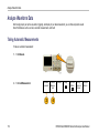
Key Features
DPO2000 and MSO2000 series oscilloscopes can help you verify, debug, and characterize electronic designs. Key features include:
200 MHz, 100 MHz, and 60 MHz bandwidths
2 channel and 4 channel models
Sample rates up to 1 GS/s on all analog channels
1 M points record length on all channels
5,000 waveforms/second waveform capture rate
I2C, SPI, CAN, LIN, RS-232, RS-422, RS-485, and UART bus triggering and analysis (with the appropriate application
module and model oscilloscope)
Wave Inspector controls for managing long record lengths, with zoom and pan, play and pause, search and mark
Large 178 mm (7 inch) WQVGA wide screen color display
Small and lightweight, at 140 mm (5.5 inch) deep and 3.6 kg (7 lbs, 14 oz)
FilterVu provides a variable low pass filter to block unwanted noise while still displaying high frequency events
x
DPO2000 and MSO2000 Series Oscilloscopes User Manual
Preface
USB flash drive port for quick and easy storage of measurement results
Direct printing to any PictBridge compatible printer
Ethernet port for remote programmability with the optional connectivity module
Video Out port to display the oscilloscope screen on an external monitor with the optional connectivity module
USB 2.0 Device port for direct PC control of the oscilloscope using USBTMC protocol
OpenChoice documentation software for simple transfer of screen shots and waveform data to a PC
National Instrument’s LabVIEW SignalExpress™ Tektronix Edition productivity and analysis software
Remote viewing and control with e*Scope
Remote control with VISA connectivity
TekVPI Versatile Probe Interface supports active, differential, and current probes for automatic scaling and units
MSO2000 series of mixed signal oscilloscopes also offer:
16 digital channels
Parallel bus triggering and analysis
Easy connection to your device-under-test through the convenient design of the P6316 digital probe
DPO2000 and MSO2000 Series Oscilloscopes User Manual
xi
Preface
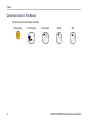
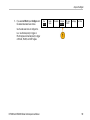
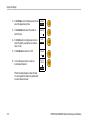
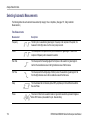
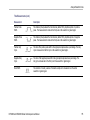
Conventions Used in This Manual
The following icons are used throughout this manual.
Sequence Step
xii
Front panel power
Connect power
Network
USB
DPO2000 and MSO2000 Series Oscilloscopes User Manual
Installation
Installation
Before Installation
Unpack the oscilloscope and check that you received all items listed as standard accessories. The following pages list
recommended accessories and probes, instrument options, and upgrades. Check the Tektronix Web site (www.tektronix.com) for
the most current information.
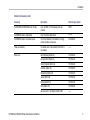
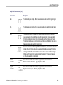
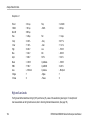
Standard Accessories
Accessory
Description
Tektronix part number
DPO2000 and MSO2000 Series Oscilloscopes
User Manual
English (Option L0)
071-2319-XX
French (Option L1)
071-2320-XX
Italian (Option L2)
071-2321-XX
German (Option L3)
071-2322-XX
Spanish (Option L4)
071-2323-XX
Japanese (Option L5)
071-2324-XX
Portuguese (Option L6)
071-2325-XX
Simple Chinese (Option L7)
071-2326-XX
Traditional Chinese (Option L8)
071-2327-XX
Korean (Option L9)
071-2328-XX
Russian (Option L10)
071-2329-XX
DPO2000 and MSO2000 Series Oscilloscopes User Manual
1
Installation
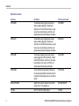
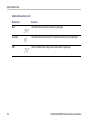
Standard Accessories (cont.)
Accessory
Description
Tektronix part number
DPO2000 and MSO2000 Series Oscilloscopes
Documentation Browser CD
Electronic versions of documents, including
the Programmer Manual and the Technical
Reference.
063-4118-XX
NI LabVIEW SignalExpress Tektronix Edition
andTektronix OpenChoice Desktop PC
Communications CDs
Productivity, analysis, and documentation
software.
063-3967-XX
——
Calibration certificate documenting traceability
to national metrology institute(s), and ISO9001
quality system registration.
Front panel overlay
2
French (Option L1)
335-2020-00
Italian (Option L2)
335-2021-00
German (Option L3)
335-2022-00
Spanish (Option L4)
335-2023-00
Japanese (Option L5)
335-2024-00
Portuguese (Option L6)
335-2025-00
Simple Chinese (Option L7)
335-2026-00
Traditional Chinese (Option L8)
335-2027-00
Korean (Option L9)
335-2028-00
Russian (Option L10)
335-2029-00
DPO2000 and MSO2000 Series Oscilloscopes User Manual
Installation
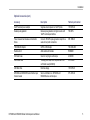
Standard Accessories (cont.)
Accessory
Description
Tektronix part number
For DPO2000 and MSO2000 series: Probes
One, 200 MHz, 1X/10X passive probe per
channel
P2221
For MSO2000 series: Digital probe
One, 16-channel digital probe
P6316
For MSO2000 series: Accessories pouch
Pouch that attaches to the handle for carrying
probes and other accessories.
016-2008-00
Three year warranty
For details, refer to the warranty in the front of
this manual
——
Power cord
North America (Option A0)
161-0348-00
Universal Euro (Option A1)
161-0343-00
United Kingdom (Option A2)
161-0344-00
Australia (Option A3)
161-0346-00
Switzerland (Option A5)
161-0347-00
Japan (Option A6)
161-0342-00
China (Option A10)
161-0341-00
India (Option A11)
161-0349-00
——
No power cord or AC adapter (Option A99)
DPO2000 and MSO2000 Series Oscilloscopes User Manual
3
Installation
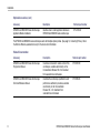
Optional Accessories
4
Accessory
Description
Tektronix part number
DPO2EMBD
The embedded serial triggering and analysis
module enables triggering on packet level
information on I2C and SPI serial buses, as well
as bus views, bus decoding, search tools, and
packet decode tables with timestamp information
DPO2EMBD
DPO2AUTO
The automotive serial triggering and analysis
module enables triggering on packet level
information on CAN and LIN serial buses, as well
as bus views, bus decoding, search tools, and
packet decode tables with timestamp information
DPO2AUTO
DPO2COMP
The computer triggering and analysis module
enables triggering on RS-232, RS-422, RS-485
and UART serial buses, search tools, bus views,
bus decoding in hex, binary, and ASCII, and
decode tables with timestamp information
DPO2COMP
DPO2CONN
The connectivity module adds an Ethernet port
for remote programmability and a Video Out port
to display the oscilloscope screen on an external
monitor
DPO2CONN
NEX-HD2HEADER
Adapter that routes the channels from a Mictor
connector to 0.1 inch header pins
NEX-HD2HEADER
TPA-BNC
TekVPI to TekProbe II BNC Adapter
TPA-BNC
DPO2000 and MSO2000 Series Oscilloscopes User Manual
Installation
Optional Accessories (cont.)
Accessory
Description
Tektronix part number
TekVPI external power adapter
Supplies external power to a TekVPI probe
119-7465-XX
Deskew pulse generator
Deskew pulse generator and signal source with
TekVPI oscilloscope interface
TEK-DPG
Power measurement deskew and calibration
fixture
Converts TEK-DPG pulse generator output into a
series of test point connections
067-1686-00
TEK-USB-488 Adapter
GPIB to USB Adapter
TEK-USB-488
Rackmount kit
Adds rackmount brackets
RMD2000
Soft transit case
Case for carrying an oscilloscope
ACD2000
Hard transit case
Traveling hard case, which requires use of the
soft transit case (ACD2000)
HCTEK4321
USB flash drive
External storage
119-7276-00
DPO2000 and MSO2000 Series Oscilloscopes
Service manual
Service information on DPO2000 and
MSO2000 series oscilloscopes
071-2331-XX
DPO2000 and MSO2000 Series Oscilloscopes User Manual
5
Installation
Optional Accessories (cont.)
Accessory
Description
Tektronix part number
DPO2000 and MSO2000 Series Oscilloscopes
Application Module Installation
Describes how to install application modules in
DPO2000 and MSO2000 series oscilloscopes
071-2330-XX
The DPO2000 and MSO2000 series oscilloscopes work with multiple optional probes. (See page 12, Connecting Probes.) Check
the Tektronix Web site (www.tektronix.com) for the most current information.
Related Documentation
6
Accessory
Description
Tektronix part number
DPO2000 and MSO2000 Series Oscilloscopes
Programmer Manual
Describes commands for remote control of the
oscilloscope; available electronically on the
Documentation Browser CD or for download
from www.tektronix.com/manuals
077-0097-XX
DPO2000 and MSO2000 Series Oscilloscopes
Technical Reference Manual
Describes the oscilloscope specifications and
performance verification procedure; available
electronically on the Documentation
Browser CD or for download from
www.tektronix.com/manuals
077-0096-XX
DPO2000 and MSO2000 Series Oscilloscopes User Manual
Installation
Operating Considerations
DPO2000 and MSO2000 Series Oscilloscopes
Input Voltage: 100 V to 240 V ±10%
Input Power Frequency:
50/60 Hz at 100 V to 240 V
400 Hz at 115 V
Power Consumption: 80 W maximum
Weight: 3.6 kg (7 lbs 14 oz), stand-alone oscilloscope
Height, including the feet but not the handle:
175 mm (6.885 inch)
Width: 377 mm (14.85 inch)
DPO2000 series
Depth: from the feet to the front of the knobs: 134 mm (5.3 inch)
Depth: from the feet to the front of the front cover: 139 mm (5.47 inch)
Clearance: 50 mm (2 inch)
DPO2000 and MSO2000 Series Oscilloscopes User Manual
7
Installation
Input Voltage (between the signal and reference):
300 VRMS CAT II
Installation Category II - for measurements performed on
circuits directly connected to the low-voltage installation
Temperature:
Operating: 0 °C to +50 °C
Nonoperating: -20 °C to +60 °C
MSO2000 series
Humidity:
Operating: High: 40 °C to 50 °C, 10% to 60% RH
Operating: Low: 0 °C to 40 °C, 10% to 90% RH
Non-operating: High: 40 °C to 60 °C, 5% to 60% RH
Non-operating: Low: 0 °C to 40 °C, 5% to 90% RH
Altitude:
Operating: 3,000 m (9,842 ft)
Nonoperating Altitude: 12,000 m (39,370 ft)
8
DPO2000 and MSO2000 Series Oscilloscopes User Manual
Installation
Random Vibration:
Operating: 0.31 GRMS, 5 - 500 Hz, 10 minutes per axis, 3 axes (30 minutes total)
Non-operating: 2.46 GRMS, 5 - 500 Hz, 10 minutes per axis, 3 axes (30 minutes total)
Pollution Degree: 2, Indoor use only
CAUTION. To ensure proper cooling, keep the sides and rear of the oscilloscope clear of obstructions.
P2221 Passive Probe
Input Voltage (between the signal and reference):
300 VRMS CAT II
Installation Category II - for measurements performed on circuits directly connected to the low-voltage installation
Temperature:
Operating: 0 °C to +50 °C (+32 °F to +122 °F)
Nonoperating: -55 °C to +75 °C ( -67 °F to +167 °F)
Pollution Degree: 2, Indoor use only
Humidity: 10% to 95% RH
DPO2000 and MSO2000 Series Oscilloscopes User Manual
9
Installation
P6316 Digital Probe
Threshold Accuracy: ±(100 mV + 3% of threshold)
Maximum signal swing: 20 Vpeak-to-peak centered around the threshold voltage
Minimum signal swing: 500 mVpeak-to-peak
Maximum nondestructive input signal to probe: 40 Vpeak-to-peak
Input resistance: 101 kΩ
Input capacitance: 8.0 pF
Temperature:
Operating: 0 °C to +50 °C (+32 °F to +122 °F)
Nonoperating: -40 °C to +71 °C (-40 °F to +160 °F)
Altitude:
Operating: 3,000 m (9,843 ft) maximum
Nonoperating: 12,000 m (39,370 ft) maximum
Pollution Degree: 2, Indoor use only
10
DPO2000 and MSO2000 Series Oscilloscopes User Manual
Installation
Humidity:
5% to 95% relative humidity
Cleaning
Inspect the oscilloscope and probes as often as operating conditions require. To clean the exterior surface, perform the following
steps:
1. Remove loose dust on the outside of the oscilloscope and probes with a lint-free cloth. Use care to avoid scratching the clear
glass display filter.
2. Use a soft cloth dampened with water to clean the oscilloscope. Use an aqueous solution of 75% isopropyl alcohol for
more efficient cleaning.
CAUTION. To avoid damage to the surface of the oscilloscope or probes, do not use any abrasive or chemical cleaning agents.
DPO2000 and MSO2000 Series Oscilloscopes User Manual
11
Installation
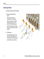
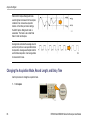
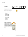
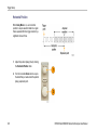
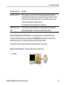
Connecting Probes
The oscilloscope supports probes with the following:
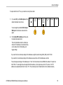
1. Tektronix Versatile Probe Interface
(TekVPI)
These probes support two-way
communication with the oscilloscope
through on-screen menus and remotely
through programmable support. The
remote control is useful in applications
like an ATE (automated test environment)
where you want the system to preset probe
parameters.
2. TPA-BNC Adapter
The TPA-BNC Adapter allows you to use
Tek Probe II probe capabilities, such as
providing probe power, and passing scaling
and unit information to the oscilloscope.
12
DPO2000 and MSO2000 Series Oscilloscopes User Manual
Installation
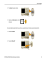
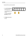
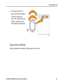
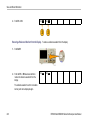
3. Plain BNC Interfaces
Some probes use TekProbe capabilities to
pass the waveform signal and scaling to
the oscilloscope. Other probes only pass
the signal and there is no communication.
4. Digital Probe Interface (MSO2000 series
only)
The P6316 probe provides 16 channels of
digital (on or off state) information.
For more information on the many probes available for use with DPO2000 and MSO2000 series oscilloscopes, refer to
www.tektronix.com.
DPO2000 and MSO2000 Series Oscilloscopes User Manual
13
Installation
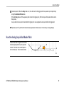
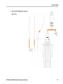
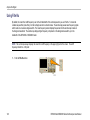
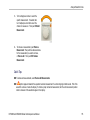
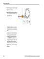
Securing the Oscilloscope
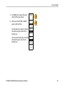
1. Use a standard laptop computer style
security lock to secure your oscilloscope
to your location.
This photo also shows the optional
DPO2CONN module installed. The module
provides an Ethernet port and a Video Out
port for the oscilloscopes.
14
DPO2000 and MSO2000 Series Oscilloscopes User Manual
Installation
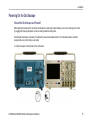
Powering On the Oscilloscope
Ground the Oscilloscope and Yourself
Before pushing the power switch, connect the oscilloscope to an electrically neutral reference point, such as earth ground. Do this
by plugging the three-pronged power cord into an outlet grounded to earth ground.
Grounding the oscilloscope is necessary for safety and to take accurate measurements. The oscilloscope needs to share the
same ground as any circuits that you are testing.
To connect the power cord and power on the oscilloscope:
DPO2000 and MSO2000 Series Oscilloscopes User Manual
15
Installation
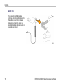
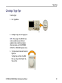
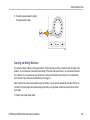
Quick Tips
If you are working with static sensitive
components, ground yourself. Static electricity
that builds up on your body can damage
static-sensitive components. Wearing a
grounding strap safely sends static charges on
your body to earth ground.
16
DPO2000 and MSO2000 Series Oscilloscopes User Manual
Installation
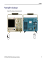
Powering Off the Oscilloscope
To power off the oscilloscope and remove the power cord:
DPO2000 and MSO2000 Series Oscilloscopes User Manual
17
Installation
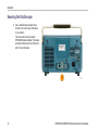
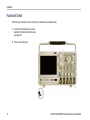
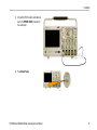
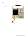
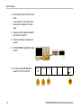
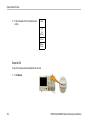
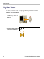
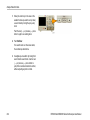
Functional Check
Perform this quick functional check to verify that your oscilloscope is operating correctly.
1. Connect the oscilloscope power cable as
described in Powering On the Oscilloscope.
(See page 15.)
2. Power on the oscilloscope.
18
DPO2000 and MSO2000 Series Oscilloscopes User Manual
Installation
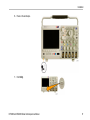
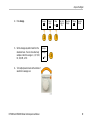
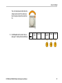
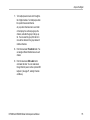
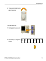
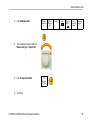
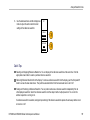
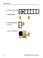
3. Connect the P2221 probe tip and reference
lead to the PROBE COMP connectors on
the oscilloscope.
4. Push Default Setup.
DPO2000 and MSO2000 Series Oscilloscopes User Manual
19
Installation
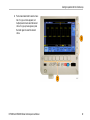
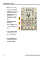
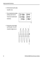
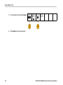
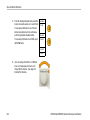
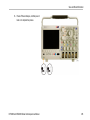
5. Push Autoset. The screen should now
display a square wave, approximately 5 V
at 1 kHz.
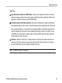
NOTE. For best performance, it is
recommended that you set the Vertical scale
to 1 V.
If the signal appears but is misshapen,
perform the procedures for compensating
the probe. (See page 21.)
If no signal appears, rerun the procedure.
If this does not remedy the situation, have
the oscilloscope serviced by qualified
service personnel.
20
DPO2000 and MSO2000 Series Oscilloscopes User Manual
Installation
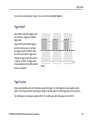
Compensating a Passive Voltage Probe
Whenever you attach a passive voltage probe for the first time to any input channel, compensate the probe to match it to
the corresponding oscilloscope input channel.
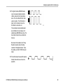
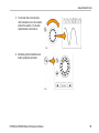
To properly compensate your passive probe:
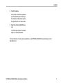
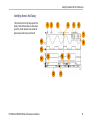
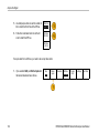
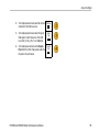
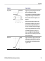
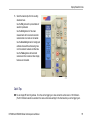
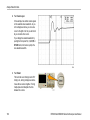
1. Follow the steps for the functional
check. (See page 18.)
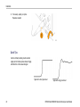
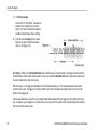
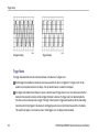
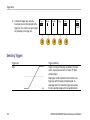
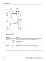
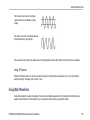
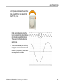
2. Check the shape of the displayed
waveform to determine if your probe
is properly compensated.
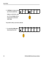
Properly compensated
DPO2000 and MSO2000 Series Oscilloscopes User Manual
Under compensated
Over compensated
21
Installation
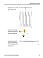
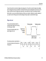
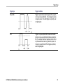
3. If necessary, adjust your probe.
Repeat as needed.
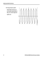
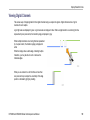
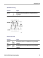
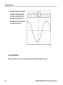
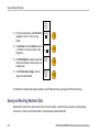
Quick Tips
Use the shortest possible ground lead and
signal path to minimize probe-induced ringing
and distortion on the measured signal.
Signal with a short ground lead
22
Signal with a long ground lead
DPO2000 and MSO2000 Series Oscilloscopes User Manual
Installation
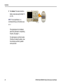
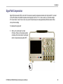
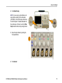
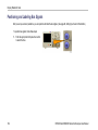
Application Module Free Trial
A 30-day free trial is available for all application modules not installed in your oscilloscope. The trial period begins when you power
on the oscilloscope for the first time.
After 30 days, you must purchase the module if you want to continue using the application. To see the date when your free trial
period expires, push the front panel Utility button, push the lower-bezel Utility Page button, use multipurpose knob a to select
Config, and push the lower-bezel About button.
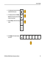
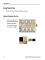
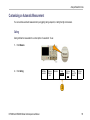
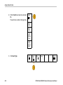
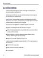
Installing an Application Module
CAUTION. To avoid damage to the oscilloscope or application module, observe ESD (electrostatic discharge) precautions.
(See page 15, Powering On the Oscilloscope.)
Turn off the oscilloscope power while removing or adding an application module.
(See page 17, Powering Off the Oscilloscope.)
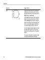
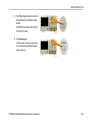
Optional application module packages extend the capability of your oscilloscope. You can install one or two application modules at
one time. An application module goes into the slot with a window in the upper right corner of the front panel. Another slot is directly
behind the one that you can see. To use this slot, install the module with the label facing away from you.
For more information on how to install and test application modules, refer to the DPO2000 and MSO2000 Series Oscilloscopes
Application Module Installation manual.
DPO2000 and MSO2000 Series Oscilloscopes User Manual
23
Installation
NOTE. If you remove an application module, the features provided by the application module become unavailable. To restore the
features, turn off the oscilloscope power, reinstall the module and turn on the oscilloscope power.
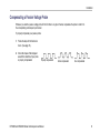
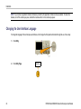
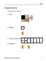
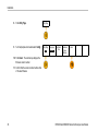
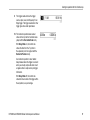
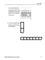
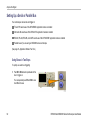
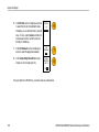
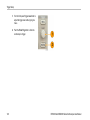
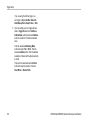
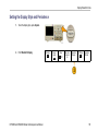
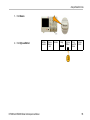
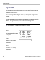
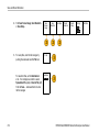
Changing the User Interface Language
To change the language of the oscilloscope user interface, and to change the front-panel button labels through the use of an overlay:
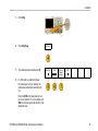
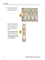
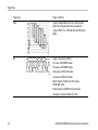
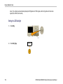
1. Push Utility.
2. Push Utility Page.
24
Utility Page
DPO2000 and MSO2000 Series Oscilloscopes User Manual
Installation
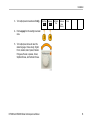
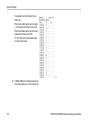
3. Turn multipurpose knob a and select Config.
Utility Page
Config
Language
English
Set Date &
Time
TekSecure
Erase
Memory
About
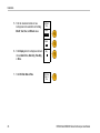
4. Push Language from the resulting lower-bezel
menu.
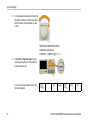
5. Turn multipurpose knob a and select the
desired language. Choose among: English,
French, German, Italian, Spanish, Brazilian
Portuguese, Russian, Japanese, Korean,
Simplified Chinese, and Traditional Chinese.
DPO2000 and MSO2000 Series Oscilloscopes User Manual
25
Installation
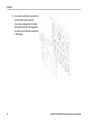
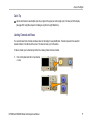
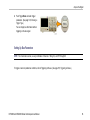
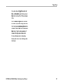
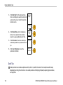
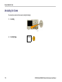
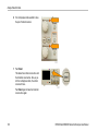
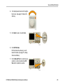
6. If you choose to use English, be sure that the
plastic front-panel overlay is removed.
If you choose a language other than English,
place the plastic overlay for the language that
you desire over the front panel to display labels
in that language.
26
DPO2000 and MSO2000 Series Oscilloscopes User Manual
Installation
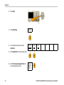
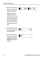
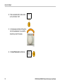
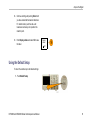
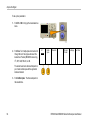
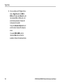
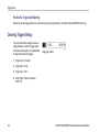
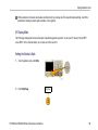
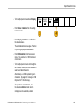
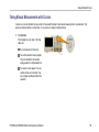
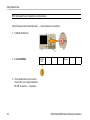
Changing the Date and Time
To set the internal clock with the current date and time:
1. Push Utility.
2. Push Utility Page.
3. Turn multipurpose knob a and select Config.
Utility Page
System
Config
Language
English
Set Date &
Time
TekSecure
Erase
Memory
About
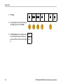
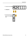
4. Push Set Date & Time.
DPO2000 and MSO2000 Series Oscilloscopes User Manual
27
Installation
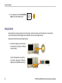
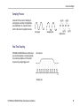
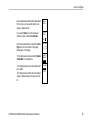
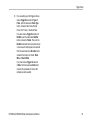
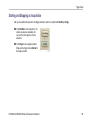
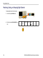
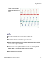
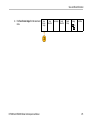
5. Push the side-bezel buttons and use
multipurpose knobs a and b to set the Day,
Month, Year, Hour, and Minute values.
Set Date &
Time
Display
Time Only
Select
Day
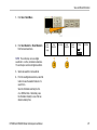
6. Push Display and turn multipurpose knob a to
choose Date & Time, Date Only, Time Only,
or None.
7. Push OK Enter Date & Time.
28
Day
3
OK Enter
Date &
Time
DPO2000 and MSO2000 Series Oscilloscopes User Manual
Installation
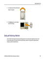
Signal Path Compensation
Signal Path Compensation (SPC) corrects for DC inaccuracies caused by temperature variations and/or long-term drift. You should
run the SPC whenever the ambient temperature has changed by more than 10 °C or once a week if you use vertical settings
of 5 mV per division or less. Failure to do so may result in the oscilloscope not meeting warranted performance levels at those
volts per division settings.
To compensate the signal path:
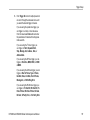
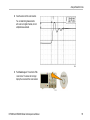
1. Warm up the oscilloscope for at least
20 minutes. Remove all input signals (probes
and cables) from channel inputs. Input signals
with AC components adversely affect SPC.
DPO2000 and MSO2000 Series Oscilloscopes User Manual
29
Installation
2. Push Utility.
3. Push Utility Page.
Utility Page
4. Turn multipurpose knob a and select
Calibration.
Utility Page
Calibration
Signal Path
Pass
Factory
Pass
5. Push Signal Path from the lower-bezel menu.
6. Push OK Compensate Signal Paths from
the resulting side-bezel menu.
30
OK Compensate
Signal
Paths
DPO2000 and MSO2000 Series Oscilloscopes User Manual
Installation
The oscilloscope displays a message when
the calibration is complete. Push Menu Off to
remove the message.
7. After calibration, verify that the status indicator
on the lower-bezel menu displays Pass.
Utility Page
Calibration
Signal Path
Pass
Factory
Pass
If it does not, then recalibrate the oscilloscope
or have the oscilloscope serviced by qualified
service personnel.
Service personnel use the factory calibration
functions to calibrate the internal voltage
references of the oscilloscope using external
sources. Refer to your Tektronix field office
or representative for assistance with factory
calibration.
NOTE. Signal Path Compensation does not include calibration to the probe tip. (See page 21, Compensating a Passive Voltage
Probe.)
DPO2000 and MSO2000 Series Oscilloscopes User Manual
31
Installation
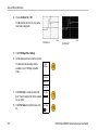
Upgrading Firmware
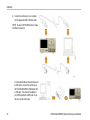
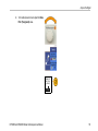
To upgrade the firmware of the oscilloscope:
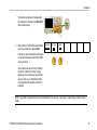
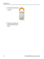
1. Open up a Web browser and go to
www.tektronix.com/software. Proceed to the
software finder. Download the latest firmware
for your oscilloscope on your PC.
Unzip the files and copy the firmware.img file
into the root folder of a USB flash drive.
32
DPO2000 and MSO2000 Series Oscilloscopes User Manual
Installation
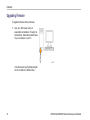
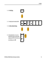
2. Power off your oscilloscope.
DPO2000 and MSO2000 Series Oscilloscopes User Manual
33
Installation
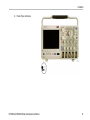
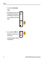
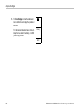
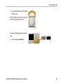
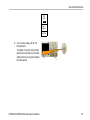
3. Insert the USB flash drive into the front-panel
USB port on your oscilloscope.
34
DPO2000 and MSO2000 Series Oscilloscopes User Manual
Installation
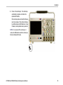
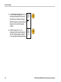
4. Power on the oscilloscope. The oscilloscope
automatically recognizes and installs the
replacement firmware.
If the oscilloscope does not install the firmware,
rerun the procedure. If the problem continues,
try a different model of USB flash drive. Finally,
if needed, contact qualified service personnel.
NOTE. Do not power off the oscilloscope or
remove the USB flash drive until the oscilloscope
finishes installing the firmware.
DPO2000 and MSO2000 Series Oscilloscopes User Manual
35
Installation
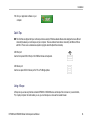
5. Power off the oscilloscope and remove the
USB flash drive.
36
DPO2000 and MSO2000 Series Oscilloscopes User Manual
Installation
6. Power on the oscilloscope.
7. Push Utility.
DPO2000 and MSO2000 Series Oscilloscopes User Manual
37
Installation
8. Push Utility Page.
Utility Page
9. Turn multipurpose knob a and select Config.
Utility Page
Config
Language
English
Set Date &
Time
TekSecure
Erase
Memory
About
10. Push About. The oscilloscope displays the
firmware version number.
11. Confirm that the version number matches that
of the new firmware.
38
DPO2000 and MSO2000 Series Oscilloscopes User Manual
Installation
Connecting Your Oscilloscope to a Computer
You may want to document your work for future reference. Instead of saving screen images and waveform data to a USB flash
drive and generating a report later, you may want to get a copy of the image or waveform data directly from a remote PC for
analysis. You may also want to control an oscilloscope at a remote location from your computer. (See page 214, Saving a Screen
Image.) (See page 216, Saving and Recalling Waveform Data.)
Two ways to connect your oscilloscope to a computer are through the VISA (Virtual Instrument Software Architecture) drivers
and the e*Scope Web-enabled tools. Use VISA to communicate with your oscilloscope from your computer through a software
application. Use e*Scope to communicate with your oscilloscope through a Web browser.
Using VISA
VISA lets you use your MS-Windows computer to acquire data from your oscilloscope for use in an analysis package that runs on
your PC, such as Microsoft Excel, National Instruments LabVIEW, or a program of your own creation. You can use a common
communications connection, such as USB or Ethernet, to connect the computer to the oscilloscope.
To set up VISA communications between your oscilloscope and a computer:
1. Load the VISA drivers on your computer.
You will find the drivers on the appropriate
CD that comes with your oscilloscope or
at the Tektronix software finder Web page
(www.tektronix.com).
DPO2000 and MSO2000 Series Oscilloscopes User Manual
39
Installation
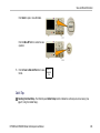
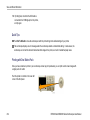
2. Connect the oscilloscope to your computer
with the appropriate USB or Ethernet cable.
NOTE. You need a DPO2CONN module to make
the Ethernet connection.
To communicate between the oscilloscope and
a GPIB system, connect the oscilloscope to
the TEK-USB-488 GPIB-to-USB Adapter with
a USB cable. Then connect the adapter to
your GPIB system with a GPIB cable. Cycle
the power on the oscilloscope.
40
DPO2000 and MSO2000 Series Oscilloscopes User Manual
Installation
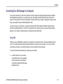
3. Push Utility.
4. Push Utility Page.
Utility Page
5. Turn multipurpose knob a and select I/O.
Utility Page
I/O
USB
Computer
Ethernet
Network
Settings
GPIB
1
6. If a USB cable is connected between
the oscilloscope and your computer, the
oscilloscope automatically sets itself up for
you.
Check the USB on the lower-bezel menu to
be sure it is enabled. If it is not enabled, push
USB and make an appropriate selection in the
side-bezel menu.
DPO2000 and MSO2000 Series Oscilloscopes User Manual
41
Installation
7. To use Ethernet, push Ethernet Network
Settings.
8. On the side-bezel menu, if you are on a DHCP
Ethernet network and using a through cable,
set DHCP to On. If you are using a cross-over
cable, set it to Off and set a hard coded TCPIP
address.
Change
Instrument
Settings
DHCP/
BOOTP
On| Off
9. If you are using GPIB, push GPIB. Enter the
GPIB address on the side-bezel menu, using
multipurpose knob a.
Talk/Listen
Address
(a) 1
This will set the GPIB address on an attached
TEK-USB-488 Adapter.
42
DPO2000 and MSO2000 Series Oscilloscopes User Manual
Installation
10. Run your application software on your
computer.
Quick Tips
The CDs that are shipped with your oscilloscope include a variety of Windows-based software tools designed to ensure efficient
connectivity between your oscilloscope and your computer. There are toolbars that enhance connectivity with Microsoft Excel
and Word. There is also a stand-alone acquisition program called the OpenChoice Desktop.
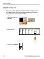
USB Host port
Use the front-panel USB 2.0 Host port for USB flash drives and keyboards.
USB Device port
Use the rear-panel USB 2.0 Device port for PCs or PictBridge printers.
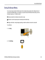
Using e*Scope
e*Scope lets you access any Internet-connected DPO2000 or MSO2000 series oscilloscope from a browser on your workstation,
PC, or laptop computer. No matter where you are, your oscilloscope is as close as the nearest browser.
DPO2000 and MSO2000 Series Oscilloscopes User Manual
43
Installation
To set up e*Scope communications between your oscilloscope and a Web browser running on a remote computer:
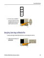
1. Connect the oscilloscope to your computer
network with the appropriate Ethernet cable.
NOTE. You need a DPO2CONN module to make
the Ethernet connection.
If you are connecting directly to your computer,
you need a Crossover Ethernet Cable. If you
are connecting to a network or a hub, you
need a Straight Through Ethernet Cable.
2. Push Utility.
44
DPO2000 and MSO2000 Series Oscilloscopes User Manual
Installation
3. Push Utility Page.
Utility Page
4. Turn multipurpose knob a and select I/O.
Utility Page
I/O
USB
Enabled
Ethernet
Network
Settings
GPIB
1
5. Push Ethernet Network Settings.
6. On the side-bezel menu, if you are on a
DHCP Ethernet network and using dynamic
addressing, set DHCP to On. If you are using
static addressing, set it to Off.
DPO2000 and MSO2000 Series Oscilloscopes User Manual
DHCP/
BOOTP
On| Off
45
Installation
7. Push Change Instrument Settings. If you
are using DHCP, note the Ethernet address
and instrument name. If you are using Static
addressing, enter the Ethernet address you
will be using.
Change
Instrument
Settings
NOTE. Depending on the type and speed of network to which your oscilloscope is connected, you may not see the DHCP/BOOTP
field update instantaneously after pressing the DHCP/BOOTP button. It may take a few seconds to update.
8. Start your browser on your remote computer. In the browser address line, enter the IP address or, if DHCP is set to On in the
oscilloscope, simply enter the instrument name.
You should now see the e*Scope screen showing the oscilloscope display on your Web browser. If e*Scope does not work,
rerun the procedure. If it still does not work, contact qualified service personnel.
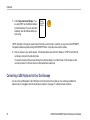
Connecting a USB Keyboard to Your Oscilloscope
You can connect a USB keyboard to the USB Host port on the front panel of the oscilloscope. The oscilloscope will detect the
keyboard, even if it is plugged in while the oscilloscope is powered on. (See page 77, Labeling Channels and Buses.)
46
DPO2000 and MSO2000 Series Oscilloscopes User Manual
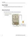
Getting Acquainted with the Oscilloscope
Getting Acquainted with the Oscilloscope
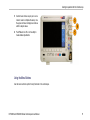
Front-Panel Menus and Controls
The front panel has buttons and controls for the functions that you use most often. Use the menu buttons to access more
specialized functions.
DPO2000 and MSO2000 Series Oscilloscopes User Manual
47
Getting Acquainted with the Oscilloscope
Using the Menu System
To use the menu system:
1. Push a front-panel menu button to display
the menu that you want to use.
48
DPO2000 and MSO2000 Series Oscilloscopes User Manual
Getting Acquainted with the Oscilloscope
2. Push a lower-bezel button to select a menu
item. If a pop-out menu appears, turn
multipurpose knob a to select the desired
choice. If a pop-up menu appears, press
the button again to select the desired
choice.
DPO2000 and MSO2000 Series Oscilloscopes User Manual
49
Getting Acquainted with the Oscilloscope
3. Push a side-bezel button to choose a
side-bezel menu item.
If the menu item contains more than
one choice, push the side-bezel button
repeatedly to cycle through the choices.
If a pop-out menu appears, turn
multipurpose knob a to select the desired
choice.
4. To remove a side-bezel menu, push the
lower-bezel button again or push Menu
Off.
50
DPO2000 and MSO2000 Series Oscilloscopes User Manual
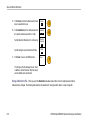
Getting Acquainted with the Oscilloscope
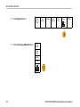
5. Certain menu choices require you to set a
numeric value to complete the setup. Use
the upper and lower multipurpose knobs a
and b to adjust values.
6. Push Fine to turn off or on the ability to
make smaller adjustments.
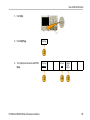
Using the Menu Buttons
Use the menu buttons to perform many functions in the oscilloscope.
DPO2000 and MSO2000 Series Oscilloscopes User Manual
51
Getting Acquainted with the Oscilloscope
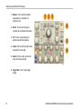
1. Measure. Push to perform automated
measurements on waveforms or to
configure cursors.
2. Search. Push to search through an
acquisition for user-defined events/criteria.
3. Test. Push to activate advanced or
application-specific testing features.
4. Acquire. Push to set the acquisition mode
and adjust the record length.
5. Autoset. Push to perform an automatic
setup of oscilloscope settings.
6. Trigger Menu. Push to specify trigger
settings.
52
DPO2000 and MSO2000 Series Oscilloscopes User Manual
Getting Acquainted with the Oscilloscope
7. Utility. Push to activate the system utility
functions, such as selecting a language or
setting the date/time.
8. Save / Recall Menu. Push to save and
recall setups, waveforms, and screen
images to internal memory, or a USB flash
drive.
9. Channel 1, 2, 3, or 4 Menu. Push to set
vertical parameters for input waveforms
and to display or remove the corresponding
waveform from the display.
DPO2000 and MSO2000 Series Oscilloscopes User Manual
53
Getting Acquainted with the Oscilloscope
10. B1 or B2. Push to define and display
a serial bus if you have the appropriate
module application keys. The DPO2AUTO
module supports CAN and LIN buses. The
DPO2EMBD module supports I2C and
SPI. The DPO2COMP module supports
RS-232, RS-422, RS-485, and UART
buses.
Parallel bus support is available on
MSO2000 products.
Also, push the B1 or B2 button to display
or remove the corresponding bus from the
display.
11. R. Push to manage reference waveforms,
including the display or removal of each
reference waveform from the display.
12. M. Push to manage the math waveform,
including the display or removal of the
math waveform from the display.
54
DPO2000 and MSO2000 Series Oscilloscopes User Manual
Getting Acquainted with the Oscilloscope
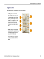
Using Other Controls
These buttons and knobs control waveforms, cursors, and other data input.
1. Turn the upper multipurpose knob a,
when activated, to move a cursor, to set
a numerical parameter value for a menu
item, or to select from a pop-out list of
choices. Push the Fine button to toggle
between coarse and fine adjustment.
Screen icons tell you when a or b are
active.
2. Cursors. Push once to activate the two
vertical cursors. Push again to turn on the
two vertical and two horizontal cursors.
Push again to turn off all cursors.
When the cursors are on, you can turn
the multipurpose knobs to control their
position.
DPO2000 and MSO2000 Series Oscilloscopes User Manual
55
Getting Acquainted with the Oscilloscope
3. Select. Push to activate special functions.
For example, when using the two vertical
cursors (and no horizontal ones are
visible), you can push this button to link or
unlink the cursors. When the two vertical
and two horizontal cursors are both visible,
you can push this button to make either the
vertical cursors or the horizontal cursors
active.
4. FilterVu. Push to filter unwanted noise
from your signal and still capture glitches.
5. Fine. Push to toggle between making
coarse and fine adjustments with the
vertical and horizontal position knobs, the
trigger level knob, and many operations of
multipurpose knobs a and b.
6. Intensity. Push to enable multipurpose
knob a to control waveform display intensity
and knob b to control graticule intensity.
56
DPO2000 and MSO2000 Series Oscilloscopes User Manual
Getting Acquainted with the Oscilloscope
7. Turn the lower multipurpose knob b,
when activated, to move a cursor or set
a numerical parameter value for a menu
item. Push Fine to make adjustments
more slowly.
8. Zoom button. Push to activate zoom
mode.
9. Pan (outer knob). Turn to scroll the zoom
window through the acquired waveform.
10. Zoom (inner knob). Turn to control the
zoom factor. Turning it clockwise zooms in
further. Turning it counterclockwise zooms
out.
11. Play-pause button. Push to start or stop
the automatic panning of a waveform.
Control the speed and direction with the
pan knob.
DPO2000 and MSO2000 Series Oscilloscopes User Manual
57
Getting Acquainted with the Oscilloscope
12. ← Prev. Push to jump to the previous
waveform mark.
13. Set/Clear Mark. Push to establish or
delete a waveform mark.
14. → Next. Push to jump to the next
waveform mark.
15. Horizontal Position. Turn to adjust
the trigger point location relative to the
acquired waveforms. Push Fine to make
smaller adjustments.
16. Horizontal Scale. Turn to adjust the
horizontal scale (time/division).
58
DPO2000 and MSO2000 Series Oscilloscopes User Manual
Getting Acquainted with the Oscilloscope
17. Run/Stop. Push to start or stop
acquisitions.
18. Single. Push to make a single acquisition.
19. Autoset. Push to automatically set the
vertical, horizontal, and trigger controls for
a usable, stable display.
20. Trigger Level. Turn to adjust the trigger
level.
Push Level to Set 50%. Push the Trigger
level knob to set the trigger level to the
midpoint of the waveform.
21. Force Trig. Push to force an immediate
trigger event.
DPO2000 and MSO2000 Series Oscilloscopes User Manual
59
Getting Acquainted with the Oscilloscope
22. Vertical Position. Turn to adjust the
vertical position of the corresponding
waveform. Push Fine to make smaller
adjustments.
23. 1, 2, 3, 4 Menu. Push to display or remove
the corresponding waveform from the
display and access the vertical menu.
24. Vertical Scale. Turn to adjust the vertical
scale factor of the corresponding waveform
(volts/division).
60
DPO2000 and MSO2000 Series Oscilloscopes User Manual
Getting Acquainted with the Oscilloscope
25. Print. Push to print to a PictBridge printer.
26. Power switch. Push to power on or off the
oscilloscope.
27. USB 2.0 Host port. Insert a USB
peripheral to the oscilloscope, such as a
keyboard or a flash drive.
28. Save. Push to perform an immediate save
operation. The save operation uses the
current save parameters, as defined in the
Save / Recall menu.
29. Default Setup. Push to perform an
immediate restore of the oscilloscope to
the default settings.
DPO2000 and MSO2000 Series Oscilloscopes User Manual
61
Getting Acquainted with the Oscilloscope
30. D15 - D0. Push to display or remove the
digital channels from the display, and to
access the digital channel setup menu
(MSO2000 series only).
31. Menu Off. Push to clear a displayed menu
from the screen.
32. Waveform Only. Push to remove menu
and readout information from the screen
so the oscilloscope only displays the
waveform or bus. Push a second time
to recall the previous menu and readout
information.
62
DPO2000 and MSO2000 Series Oscilloscopes User Manual
Getting Acquainted with the Oscilloscope
Identifying Items in the Display
The items shown to the right may appear in the
display. Not all of these items are visible at any
given time. Some readouts move outside the
graticule area when menus are turned off.
DPO2000 and MSO2000 Series Oscilloscopes User Manual
63
Getting Acquainted with the Oscilloscope
1. The acquisition readout shows when an
acquisition is running, stopped, or when
acquisition preview is in effect. Icons are:
Run: Acquisitions enabled
Stop: Acquisitions not enabled
Roll: In Roll mode (40 ms per division
or slower)
PreVu: In this state, the oscilloscope
is stopped or between triggers. You
can change the horizontal or vertical
position or scale to see approximately
what the next acquisition will look like.
2. The trigger status readout shows trigger
status. Status conditions are:
Trig’d: Triggered
Auto: Acquiring untriggered data
PrTrig: Acquiring pretrigger data
Trig?: Waiting for trigger
64
DPO2000 and MSO2000 Series Oscilloscopes User Manual
Getting Acquainted with the Oscilloscope
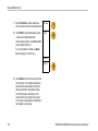
3. The trigger position icon shows where the
trigger occurred in the acquisition.
4. The expansion point icon (an orange
triangle) shows the point that the horizontal
scale expands and compresses around.
5. The waveform record view shows the
trigger location relative to the waveform
record. The line color corresponds to the
selected waveform color.
DPO2000 and MSO2000 Series Oscilloscopes User Manual
65
Getting Acquainted with the Oscilloscope
6. The FilterVu indicator shows if the variable
low pass filter is active.
7. The cursor readout shows time, amplitude,
and delta (Δ) values for each cursor.
For serial buses, the readout shows the
decoded values.
8. The trigger level icon shows the trigger
level on the waveform. The icon color
corresponds to the trigger source color.
66
DPO2000 and MSO2000 Series Oscilloscopes User Manual
Getting Acquainted with the Oscilloscope
9. The trigger readout shows the trigger
source, slope, level, and frequency for an
Edge trigger. The trigger readouts for other
trigger types show other parameters.
10. The horizontal position/scale readout
shows on the top line the horizontal scale
(adjust with the Horizontal Scale knob).
With Delay Mode on, the bottom line
shows the time from the T symbol to
the expansion point icon (adjust with the
Horizontal Position knob).
Use horizontal position to insert added
delay between when the trigger occurs and
when you actually capture the data. Insert
a negative time to capture more pretrigger
information.
With Delay Mode off, the bottom line
shows the time location of the trigger within
the acquisition, as a percentage.
DPO2000 and MSO2000 Series Oscilloscopes User Manual
67
Getting Acquainted with the Oscilloscope
11. Measurement readouts show the selected
measurements. You can select up to four
measurements to display at one time.
A
symbol appears instead of the
expected numerical measurement if a
vertical clipping condition exists. Part of the
waveform is above or below the display. To
obtain a proper numerical measurement,
turn the vertical scale and position knobs
to make all of the waveform appear in the
display.
12. The auxiliary waveform readouts show the
vertical and horizontal scale factors of the
math and reference waveforms.
13. The channel readout shows the channel
scale factor (per division), coupling, invert,
and bandwidth status. Adjust with the
Vertical Scale knob and the channel 1, 2,
3, or 4 menus.
68
DPO2000 and MSO2000 Series Oscilloscopes User Manual
Getting Acquainted with the Oscilloscope
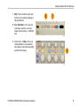
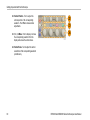
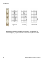
14. For digital channels (MSO2000 series
only), the baseline indicators label the
channel, and point to the high and low
levels. The colors follow the color code
used on resistors. The D0 indicator is
black, the D1 indicator is brown, the
D2 indicator is red, and so on.
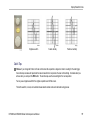
The bus display shows decoded packet
level information for serial buses or for
parallel buses (MSO2000 series only). The
bus indicator shows the bus number and
bus type.
Not shown in this illustration, the Timing
Resolution readout shows the timing
resolution of the digital channels. To see
the readout, push the D15-D0 front panel
button.
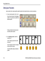
15. For math channels, the waveform baseline
indicator shows the zero-volt level of a
waveform.
DPO2000 and MSO2000 Series Oscilloscopes User Manual
69
Getting Acquainted with the Oscilloscope
16. For analog channels, the waveform
baseline indicator shows the zero-volt
level of a waveform (ignoring the effect of
offset). The icon colors correspond to the
waveform colors.
70
DPO2000 and MSO2000 Series Oscilloscopes User Manual
Getting Acquainted with the Oscilloscope
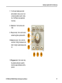
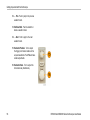
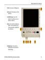
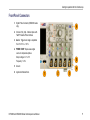
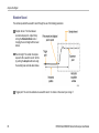
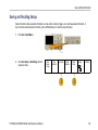
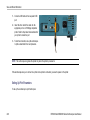
Front-Panel Connectors
1. Digital Probe Connector (MSO2000 series
only).
2. Channel 1, 2, (3, 4). Channel inputs with
TekVPI Versatile Probe Interface.
3. Aux In. Trigger level range is adjustable
from +12.5 V to –12.5 V.
4. PROBE COMP. Square wave signal
source to compensate probes.
Output voltage: 0 V to 5 V
Frequency: 1 kHz
5. Ground.
6. Application Module Slots.
DPO2000 and MSO2000 Series Oscilloscopes User Manual
71
Getting Acquainted with the Oscilloscope
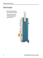
Side-Panel Connector
1. TekVPI external power supply connector.
Use the connector for the TekVPI external
power supply (Tektronix part number
119-7465-XX) when additional power is
needed for TekVPI probes.
72
DPO2000 and MSO2000 Series Oscilloscopes User Manual
Getting Acquainted with the Oscilloscope
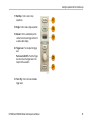
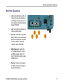
Rear-Panel Connectors
1. LAN. Use the LAN (Ethernet) port (RJ-45
connector) to connect the oscilloscope to
a 10/100 Base-T local area network. The
port is available on the optional connectivity
module (DPO2CONN).
2. Lock. Use to secure the oscilloscope and
optional connectivitiy module.
3. Video Out. Use the Video Out port (DB-15
female connector) to show the oscilloscope
display on an external monitor or projector.
The port is available on the optional
connectivity module (DPO2CONN).
4. USB 2.0 Device port. Use the USB
2.0 Full Speed Device port to connect
a PictBridge compatible printer, or for
direct PC control of the oscilloscope using
USBTMC protocol.
5. Power input. Attach to an AC power line
with integral safety ground. (See page 7,
Operating Considerations.)
DPO2000 and MSO2000 Series Oscilloscopes User Manual
73
Acquire the Signal
Acquire the Signal
This section describes concepts of and procedures for setting up the oscilloscope to acquire the signal as you want it to.
Setting Up Analog Channels
Use front-panel buttons and knobs to set up your oscilloscope to acquire signals using the analog channels.
1. Connect a P2221 probe or a TekVPI probe
to the input signal source.
74
DPO2000 and MSO2000 Series Oscilloscopes User Manual
Acquire the Signal
2. Push Default Setup.
NOTE. If you are using a probe that does not
supply probe encoding, set the attenuation
(probe factor) on the oscilloscope vertical menu
to match the probe. The default attenuation for
the oscilloscope is 10X and is set in the Probe
Setup lower-bezel menu of any analog channel.
3. Select the input channel by pushing the
front-panel buttons.
4. Push Autoset.
DPO2000 and MSO2000 Series Oscilloscopes User Manual
75
Acquire the Signal
5. Push the desired channel button. Then
adjust the vertical position and scale.
6. Adjust the horizontal position and scale.
The horizontal position determines the
number of pretrigger and posttrigger
samples.
The horizontal scale determines the size
of the acquisition window relative to the
waveform. You can scale the window to
contain a waveform edge, a cycle, several
cycles, or thousands of cycles.
76
DPO2000 and MSO2000 Series Oscilloscopes User Manual
Acquire the Signal
Quick Tip
Use the zoom feature to see multiple cycles of your signal in the upper part, and a single cycle in the lower part of the display.
(See page 198, Using Wave Inspector to Manage Long Record Length Waveforms.)
Labeling Channels and Buses
You can add a label to the channels and buses shown on the display for easy identification. The label is placed on the waveform
baseline indicator in the left side of the screen. The label can have up to 32 characters.
To label a channel, push a channel input button for an analog channel to label a channel.
1. Push a front panel button for an input channel
or a bus.
DPO2000 and MSO2000 Series Oscilloscopes User Manual
77
Acquire the Signal
2. Push a lower-bezel button to create a label,
such as for channel 1 or B1.
Label
3. Turn multipurpose knob b to scroll through the
list to find a suitable label. You can edit the
label after you insert it if necessary.
4. Push Insert Preset Label to add the label.
78
Insert
Preset
Label
DPO2000 and MSO2000 Series Oscilloscopes User Manual
Acquire the Signal
If you are using a USB keyboard, use the
arrow keys to position the insertion point and
edit the inserted label, or type in a new label.
(See page 46, Connecting a USB Keyboard
to Your Oscilloscope.)
5. If you do not have a USB keyboard connected,
push the side- and lower-bezel arrow keys to
position the insertion point.
DPO2000 and MSO2000 Series Oscilloscopes User Manual
79
Acquire the Signal
6. Turn multipurpose knob a to scroll through the
list of letters, numbers, and other characters to
find the character in the name that you want
to enter.
ABCDEFGHIJKLMNOPQRSTUVWXYZ
abcdefghijklmnopqrstuvwxyz
0123456789_=+-!@#$%^&*()[]{}<>/~’”\|:,.?
7. Push Select or Enter Character to let the
oscilloscope know that you have picked the
proper character to use.
You can use the lower-bezel buttons to edit
the label as needed.
80
Enter
Character
Back
Space
Delete
Clear
DPO2000 and MSO2000 Series Oscilloscopes User Manual
Acquire the Signal
8. Continue scrolling and pushing Select until
you have entered all the desired characters.
For another label, push the side- and
lower-bezel arrow keys to reposition the
insertion point.
9. Push Display Labels and select On to see
the label.
Display
Labels
On| Off
Using the Default Setup
To return the oscilloscope to its default settings:
1. Push Default Setup.
DPO2000 and MSO2000 Series Oscilloscopes User Manual
81
Acquire the Signal
2. If you change your mind, push Undo Default
Setup to undo the last default setup.
Undo
Default
Setup
Using Autoset
Autoset adjusts the oscilloscope (acquisition, horizontal, trigger, and vertical controls) such that it displays four or five waveform
cycles for analog channels with the trigger near the middle level, and ten cycles for digital channels.
Autoset works with both the analog and digital channels.
1. Connect the analog probe, and then select
the input channel. (See page 74, Setting Up
Analog Channels.)
Connect the digital probe and select the
input channel. (See page 112, Setting Up
Digital Channels (MSO2000 Series Only).)
82
DPO2000 and MSO2000 Series Oscilloscopes User Manual
Acquire the Signal
2. Push Autoset to execute an Autoset.
3. If desired, push Undo Autoset to undo the
last Autoset.
Undo
Autoset
You can also disable the Autoset function if you want to set up a waveform manually. To disable or enable the Autoset function:
1. Push and hold Autoset.
2. Push and hold Menu Off.
DPO2000 and MSO2000 Series Oscilloscopes User Manual
83
Acquire the Signal
3. Release Menu Off, and then release
Autoset.
4. Select the desired side-bezel setting.
Autoset
Enabled
Autoset
Disabled
Quick Tips
To position the waveform appropriately, Autoset may change the vertical position. Autoset always sets vertical offset to 0 V.
If you use Autoset when no channels are displayed, the oscilloscope turns on channel one (1) and scales it.
Acquisition Concepts
Before a signal can be displayed, it must pass through the input channel where it is scaled and digitized. Each channel has a
dedicated input amplifier and digitizer. Each channel produces a stream of digital data from which the oscilloscope extracts
waveform records.
84
DPO2000 and MSO2000 Series Oscilloscopes User Manual
Acquire the Signal
Sampling Process
Acquisition is the process of sampling an
analog signal, converting it into digital data,
and assembling it into a waveform record,
which is then stored in acquisition memory.
Input signal
Sampled points
Digital values
Real-Time Sampling
DPO2000 and MSO2000 series oscilloscopes
use real-time sampling. In real-time sampling,
the oscilloscope digitizes all of the points it
acquires using a single trigger event.
Record points
Sampling rate
DPO2000 and MSO2000 Series Oscilloscopes User Manual
85
Acquire the Signal
Waveform Record
The oscilloscope builds the waveform record through the use of the following parameters:
Sample interval: The time between
recorded sample points. Adjust this by
turning the Horizontal Scale knob or
changing the record length with the bezel
buttons.
Record length: The number of samples
required to fill a waveform record. Set this
by pushing the Acquire button and using
the resulting lower- and side-bezel menus.
Trigger point: The zero time reference in a waveform record. It is shown on the screen by an orange T.
86
DPO2000 and MSO2000 Series Oscilloscopes User Manual
Acquire the Signal
Horizontal position: When the Delay mode is on, this is the time from the trigger point to the expansion point. Adjust this by
turning the Horizontal Position knob.
When the Delay mode is off, the expansion point is fixed to the trigger point. (Push the Acquire front panel button to set the
Delay mode.)
Use a positive time to acquire the record after the trigger point. Use a negative time to acquire it before the trigger point.
Expansion point: The point that the horizontal scale expands and contracts around. It is shown by an orange triangle.
How the Analog Acquisition Modes Work
FilterVu Noise Filter Foreground mode retains
the first sampled point from each acquisition
interval. This mode is also called Sample in
other oscilloscopes. This is the default mode.
DPO2000 and MSO2000 Series Oscilloscopes User Manual
87
Acquire the Signal
FilterVu Glitch Capture Background mode
uses the highest and lowest of all the samples
contained in two consecutive acquisition
intervals. At fast time per division settings,
the Glitch Capture Background mode is
unavailable. This mode is also called Peak
Detect in other oscilloscopes.
Average mode calculates the average value for
each record point over a user-specified number
of acquisitions. Average uses Sample mode for
each individual acquisition. Use Average mode
to reduce random noise.
Changing the Acquisition Mode, Record Length, and Delay Time
Use this procedure to change the acquisition mode.
1. Push Acquire.
88
DPO2000 and MSO2000 Series Oscilloscopes User Manual
Acquire the Signal
2. Push Average.
3. Set the Average acquisition mode from the
side-bezel menu. You can chose how many
samples on which to average: 2, 4, 8, 16, 32,
64, 128, 256, or 512.
Average
Off
Record
Length
100k
Delay
On |Off
Set Horiz.
Position to
10%
Waveform
Display
XY Display
Off
Acquisition
Details
Average
Average
On |Off
4. Turn multipurpose knob a to set the number of
waveforms to average over.
DPO2000 and MSO2000 Series Oscilloscopes User Manual
89
Acquire the Signal
5. Push Record Length.
Choose 100 k or 1.00 M points. The selections
depend on the horizontal time per division
setting. 125 k and 1.25 M records lengths are
available at slower time per division settings.
6. Push the lower-bezel Delay button to select
On when you want to delay the acquisition
relative to the trigger event.
With Delay set to On, turn the Horizontal Position knob counterclockwise to increase the delay. The trigger point will move to the
left and ultimately outside of the acquired waveform. Then you can adjust the Horizontal Scale knob to acquire more detail around
the area of interest at the center of the screen.
When this delay is on, the trigger point separates from the horizontal expansion point. The horizontal expansion point stays at
the center of the screen. The trigger point can move off the screen. When this happens, the trigger marker turns to point in the
direction of the trigger point.
Use the delay feature when you want to acquire waveform detail that is separated from the trigger event by a significant interval of
time. For example, you can trigger on a sync pulse that occurs once every 10 ms and then look at high-speed signal characteristics
that occur 6 ms after the sync pulse.
90
DPO2000 and MSO2000 Series Oscilloscopes User Manual
Acquire the Signal
When the delay feature is set to Off, the expansion point is tied to the trigger point so that scale changes are centered around the
trigger point.
Using Roll Mode
Roll mode gives a display similar to a strip chart recorder for low-frequency signals. Roll mode lets you see acquired data points
without waiting for the acquisition of a complete waveform record.
Roll mode is enabled when the trigger mode is auto and the horizontal scale is set to 40 ms/division or slower.
Quick Tips
Roll mode is disabled when you switch to Average acquisition mode, use digital channels, use math waveforms, turn on a bus,
switch to Normal trigger, or set the horizontal scale to 20 ms per division or faster.
Zoom is disabled when you use Roll mode.
Push Run/Stop to halt Roll mode.
DPO2000 and MSO2000 Series Oscilloscopes User Manual
91
Acquire the Signal
Setting Up a Serial or Parallel Bus
Your oscilloscope can decode and trigger on:
I2C and SPI serial buses if the DPO2EMBD application module is installed
CAN and LIN serial buses if the DPO2AUTO application module is installed
RS-232, RS-422, RS-485, and UART serial buses if the DPO2COMP application module is installed
Parallel buses if you are using an MSO2000 series oscilloscope
(See page 23, Application Module Free Trial.)
Using Buses in Two Steps
To quickly use serial bus triggering:
1. Push B1 or B2 and enter parameters of the
bus to trigger on.
You can separately use B1 and B2 to view
two different buses.
92
DPO2000 and MSO2000 Series Oscilloscopes User Manual
Acquire the Signal
2. Push Trigger Menu and enter trigger
parameters. (See page 129, Choosing a
Trigger Type.)
You can display bus information without
triggering on the bus signal.
Setting Up Bus Parameters
NOTE. For all serial bus sources, use any combination of channels 1 through 4, and D15 through D0.
To trigger on serial or parallel bus conditions, refer to Triggering on Buses. (See page 135, Triggering on Buses.)
DPO2000 and MSO2000 Series Oscilloscopes User Manual
93
Acquire the Signal
To set up bus parameters:
1. Push B1 or B2 to bring up the lower-bezel bus
menu.
2. Push Bus. Turn multipurpose knob a to scroll
through the list of bus types and select the
desired bus: Parallel (MSO2000 series only),
I2C, SPI, CAN, RS-232, or LIN.
B1
Parallel
Define
Inputs
Thresholds
B1 Label
Parallel
Bus Display
Event Table
The actual menu items shown will depend on
your model oscilloscope and the application
modules installed.
3. Push Define Inputs. The choices depend on
the selected bus.
94
DPO2000 and MSO2000 Series Oscilloscopes User Manual
Acquire the Signal
Use the side-bezel buttons to define parameters
for the inputs, such as specific signals to an
analog or digital channel.
Define
Inputs
If you select Parallel, push the side-bezel
button to enable or disable Clocked Data.
Clocked
Data
Yes|No
Push the side-bezel button to select the Clock
Edge on which to clock data: rising edge,
falling edge, or both edges.
Clock Edge
Turn multipurpose knob a to select the Number
of Data Bits in the parallel bus.
Number of
Data Bits
(a) 16
Turn multipurpose knob a to select the desired
bit to define.
Turn multipurpose knob b to select the desired
analog or digital channel as the source for the
bit.
Define Bits
(a) Bit 15
(b) D15
DPO2000 and MSO2000 Series Oscilloscopes User Manual
95
Acquire the Signal
4. Push Thresholds.
Bus
Parallel
Define
Inputs
Thresholds
B1 Label
Parallel
Bus Display
Event Table
You can set the threshold for all channels in the
parallel or serial bus from a list of preset values.
The values are based on common types of
integrated circuits. The preset values are:
1.4 V for TTL
2.5 V for 5.0 V CMOS
1.65 V for 3.3 V CMOS
1.25 V for 2.5 V CMOS
-1.3 V for ECL
3.7 V for PECL
0V
Alternately, you can set the threshold to a
specific value for the signals that makes up the
parallel or serial bus. To do so, push the Select
side-bezel button and turn multipurpose knob
a to select a Bit or a Channel number (Signal
name).
96
DPO2000 and MSO2000 Series Oscilloscopes User Manual
Acquire the Signal
Then, turn multipurpose knob b to define the
voltage level above which the oscilloscope
treats the signal as high and below which as
low.
5. Push B1 Label to edit the label for the bus.
(See page 77, Labeling Channels and Buses.)
DPO2000 and MSO2000 Series Oscilloscopes User Manual
Bus
Parallel
Define
Inputs
Thresholds
B1 Label
Parallel
Bus Display
Event Table
97
Acquire the Signal
6. Push Bus Display and use the side-bezel
menu to define how to display the parallel or
serial bus.
Push the desired side-bezel menu choice to
display the bus data in hex, binary, or ASCII
(RS-232 only) format.
Hex
Binary
ASCII
98
DPO2000 and MSO2000 Series Oscilloscopes User Manual
Acquire the Signal
7. Push Event Table and select On to display a
list of I2C, SPI, CAN, or LIN bus packets with
timestamps.
Event
Table
On |Off
Save Event
Table
For a clocked parallel bus, the table lists the
value of the bus at each clock edge. For an
unclocked parallel bus, the table lists the value
of the bus whenever any one of its bits changes.
For an RS-232 bus, the table lists decoded
bytes, or packets.
8. Push Save Event Table to save the event table
data in a .csv (spreadsheet) formatted file on
the currently selected storage device.
DPO2000 and MSO2000 Series Oscilloscopes User Manual
99
Acquire the Signal
This example of an Event Table is from an
RS-232 bus.
RS-232 event tables display one line for each
7- or 8-bit byte when Packets are set to Off.
RS-232 event tables display one line for each
packet when Packets are set to On.
I2C, SPI, CAN, and LIN event tables display
one line for each packet.
9. Push B1 or B2 and turn multipurpose knob a to
move the bus display up or down on the screen.
100
DPO2000 and MSO2000 Series Oscilloscopes User Manual
Acquire the Signal
To acquire data from an I2C bus, you need to also set up these items:
1. If you select I2C, push Define Inputs and the
desired side-bezel menu choices.
B1
I2C
Define
Inputs
Thresholds
Include
R/W in
Address
No
B1 Label
I2C
Bus Display
Event Table
You can assign the predefined SCLK Input or
SDA Input to the channel connected to the
signal.
2. Push Include R/W in Address and then push
the desired side-bezel button.
This control determines how the oscilloscope
shows the I2C addresses in bus decode traces,
cursor readouts, Event Table listings, and
trigger settings.
If you select Yes, the oscilloscope displays 7-bit addresses as eight bits, where the eighth bit (LSB) is the R/~W bit.
If you select No, the oscilloscope displays 7-bit addresses as seven bits, and 10-bit addresses as ten bits.
The oscilloscope also displays 10-bit addresses as 11 bits. The first two bits are the two MSBs of the address. The next bit is
the R/~W bit. The last eight bits are the eight LSBs of the address. (In the physical layer of the I2C protocol, 10 bit I2C
addresses are preceded by the five bit code, 11110. The oscilloscope never includes these five bits in address readouts.)
DPO2000 and MSO2000 Series Oscilloscopes User Manual
101
Acquire the Signal
To acquire data from an SPI bus, you need to also set up these items:
1. If you selected SPI, push Define Inputs and
the desired side-bezel menu choices.
Bus
SPI
Define
Inputs
Thresholds
Configure
B1 Label
SPI
Bus Display
Event Table
You can set the Framing to SS (Slave Select)
or to Idle Time.
You can assign the predefined SCLK, SS,
MOSI, or MISO signals to any channel.
2. Push Configure and the desired side-bezel
menu choices.
102
DPO2000 and MSO2000 Series Oscilloscopes User Manual
Acquire the Signal
3. Push SCLK to set the edge of the signal to
match the SPI bus being acquired.
4. Set the level of the SS, MOSI, and MISO
signals to match the SPI bus.
SCLK
SS
Active High
Active Low
Active High means that a signal is considered
active when the signal is greater than the
threshold value.
MOSI
Active High
Active Low
Active Low means that the signal is considered
active when the signal is lower than the
threshold value.
MISO
Active High
Active Low
-more1 0f 2
DPO2000 and MSO2000 Series Oscilloscopes User Manual
103
Acquire the Signal
5. Use multipurpose knob a to set the number of
bits to match the Word Size of the SPI bus.
Word Size
(a) 8 bits
6. Push either side bezel button to set the bit
order to match the SPI bus.
Bit Order
MS First
Bit Order
LS First
To acquire data from a CAN bus, you need to also set up these items:
1. If you selected CAN, push Define Inputs and
the desired side-bezel menu choices.
104
Bus
CAN
Define
Inputs
Thresholds
Bit Rate
500 Kbps
B1 Label
CAN
Bus Display
Event Table
DPO2000 and MSO2000 Series Oscilloscopes User Manual
Acquire the Signal
2. Turn multipurpose knob a to select the channel
connected to the CAN bus source.
CAN Input
(a) 1
3. Turn multipurpose knob a to select the type of
CAN signal to match the source of the CAN
bus: CAN_H, CAN_L, Rx, Tx, or Differential.
Signal
Type
CAN_H
4. Turn multipurpose knob a to set the Sample
Point from 5% to 95% of the position within the
bit period or the unit interval.
Sample
Point
50%
DPO2000 and MSO2000 Series Oscilloscopes User Manual
105
Acquire the Signal
5. Push Bit Rate and turn multipurpose knob a to
select from the list of predefined bit rates.
Bus
CAN
Define
Inputs
Thresholds
Bit Rate
500 Kbps
B1 Label
CAN
Bus Display
Event Table
Thresholds
Configure
B1 Label
LIN
Bus Display
Event Table
Alternately, you can set the bit rate to a specific
value. To do so, select Custom, and then turn
multipurpose knob b to set the bit rate from
10000 to 1000000.
To acquire data from a LIN bus, you need to also set up these items:
1. If you selected LIN, push Define Inputs and
the desired side-bezel menu choices.
106
Bus
LIN
Define
Inputs
DPO2000 and MSO2000 Series Oscilloscopes User Manual
Acquire the Signal
2. Turn multipurpose knob a to select the channel
connected to the LIN bus source.
LIN Input
(a) 1
3. Turn multipurpose knob a to set the Sample
Point from 5% to 95% of the position within the
bit period or the unit interval.
Sample
Point
50%
4. Select the Polarity to match the LIN bus being
acquired.
Polarity
Normal
(High=1)
Polarity
Inverted
(High=0)
5. Push Configure and the desired side-bezel
menu choices.
DPO2000 and MSO2000 Series Oscilloscopes User Manual
Bus
LIN
Define
Inputs
Thresholds
Configure
B1 Label
LIN
Bus Display
Event Table
107
Acquire the Signal
6. Push Bit Rate, and turn multipurpose knob a
to select from the list of predefined bit rates.
Alternately, you can set the bit rate to a specific
value. To do so, select Custom, and then turn
multipurpose knob b to set the bit rate from
800 bps to 100000 bps.
Bit Rate
(a)
19.2K bps
7. Push LIN Standard, and turn multipurpose
knob a to select the appropriate standard.
LIN
Standard
v1.x
8. Push Include Parity Bits with Id to select
whether or not to include parity bits.
Include
Parity Bits
with Id
On|Off
To acquire data from a RS-232 bus, you need to also set up these items:
108
DPO2000 and MSO2000 Series Oscilloscopes User Manual
Acquire the Signal
1. If you selected RS-232, push Configure and
the desired side-bezel menu choices.
Bus
RS-232
Define
Inputs
Thresholds
Configure
9600-8-N
B1 Label
RS-232
Bus Display
Event Table
Use the side-bezel menu to configure the
bus. Use Normal polarity to trigger on
RS-232 signals and Inverted polarity to trigger
on RS-422, RS-485, and UART signals.
DPO2000 and MSO2000 Series Oscilloscopes User Manual
109
Acquire the Signal
2. Push Bit Rate, and turn multipurpose knob a to
select the appropriate bit rate.
Bit Rate
9600 bps
3. Push Data Bits and select the number to
match the bus.
Data Bits
4. Push Parity and turn multipurpose knob a to
match the polarity used by the bus as None,
Odd, or Even.
Parity
(a) None
5. Push Packets and select On or Off.
Packets
7 |8
On|Off
6. Turn multipurpose knob a to select an
end-of-packet character.
End of
Packet
0A
(Linefeed)
RS-232 decoding displays a stream of bytes.
You can organize the stream into packets with
an end-of-packet character
110
DPO2000 and MSO2000 Series Oscilloscopes User Manual
Acquire the Signal
Physical Layer Bus Activity
Oscilloscope waveform traces from analog channels 1 to 4, digital channels D15 to D0, and the traces you see when you choose to
display a bus always show the physical layer bus activity. In the physical layer display, bits that were transmitted earlier are to
the left, and bits that were transmitted later are to the right.
I2C, and CAN buses transmit the MSB (most significant bit) first
SPI buses do not specify a bit order
RS-232 and LIN buses transmit the LSB (least significant bit) first
NOTE. The oscilloscope displays the decode traces and event tables for all buses with the MSB on the left and LSB on the right.
For example, an RS-232 signal (after the start bit) might be high, high, high, low, high, low, low, and high. Since the RS-232 protocol
uses high for zero and low for one, this value would be 0001 0110.
Since the decode displays the MSB first, the oscilloscope reverses the order of the bits and displays 0110 1000. If the bus display is
set to hex, the value displays as 68. If the bus display is set to ASCII, the value displays as h.
RS-232
If you defined an end-of-packet character to
use for RS-232 decoding, the stream of bytes
will be displayed as packets.
DPO2000 and MSO2000 Series Oscilloscopes User Manual
111
Acquire the Signal
When decoding an RS-232 bus in ASCII mode,
a large dot indicates that the value represents
a character outside the printable ASCII range.
Setting Up Digital Channels (MSO2000 Series Only)
Use front-panel buttons and knobs to set up your oscilloscope to acquire signals using the digital channels available only
on MSO2000 models.
112
DPO2000 and MSO2000 Series Oscilloscopes User Manual
Acquire the Signal
1. Connect the P6316 digital probe to the input
signal source.
DPO2000 and MSO2000 Series Oscilloscopes User Manual
113
Acquire the Signal
2. Connect the ground lead or leads to the circuit
ground.
You can connect one or two of the common
ground leads for each group of 8 channels
(wires).
3. If needed, connect the appropriate grabber for
each channel to the probe tip.
4. Connect each channel to the desired circuit
test point.
5. Push the D15 - D0 front panel button to display
the menu.
6. Push the lower-bezel D15 - D0 button to
access the D15 - D0 On or Off menu.
114
D15 – D0
On/Off
Thresholds
Edit Labels
Height
S|ML
DPO2000 and MSO2000 Series Oscilloscopes User Manual
Acquire the Signal
7. Turn multipurpose knob a to scroll through the
list of digital channels. Turn multipurpose knob
b to position the selected channel.
As you position channels close to each other
on the display, the oscilloscope groups the
channels, and adds the group to the pop-up
list. You can select the group from the list to
move all the channels in the group instead of
individual channels.
8. Push the lower-bezel Thresholds button. You
can assign a different threshold value to each
channel.
9. Push the lower-bezel Edit Labels button
and create the label. You can create labels
through the front panel or with an optional USB
keyboard. (See page 77, Labeling Channels
and Buses.)
DPO2000 and MSO2000 Series Oscilloscopes User Manual
115
Acquire the Signal
10. Push the lower-bezel Height button repeatedly
to set the signal height. You only need to do
this once to set the height for all of the digital
channels.
Quick Tip
Use the zoom feature to see multiple cycles of the signal in the upper part, and a single cycle in the lower part of the display.
(See page 198, Using Wave Inspector to Manage Long Record Length Waveforms.)
The lead for each digital channel has a color-coded band for easy identification. The ground leads are shorter and have
black wires.
Digital channels store a high or low state for each sample. The threshold that separates a high from a low can be set for all the
channels in GROUP 1 or in GROUP 2. The threshold can not be set for individual channels.
Reducing Unwanted Noise With FilterVu
You can use FilterVu to filter unwanted noise from your signal and still capture glitches. The oscilloscope does this by superimposing
a filtered foreground waveform over a glitch capture background waveform.
The filtered waveform uses a variable low-pass filter to block out noise, yielding a cleaner waveform. When the noise filter
is adjusted to the minimum bandwidth setting, no more than 1% of high-frequency content that could cause the oscilloscope
to alias will pass through the filter.
116
DPO2000 and MSO2000 Series Oscilloscopes User Manual
Acquire the Signal
The glitch capture waveform shows signal details up to the full bandwidth of the oscilloscope. The oscilloscope captures pulses as
narrow as 5 ns, using peak detect min/max sampling.
When your signal is filtered, the glitch capture waveform changes color to distinguish it from the filtered waveform. When the signal
is filtered, you can independently adjust the intensity of the glitch capture waveform. When the signal is not filtered, the intensity of
the glitch capture waveform depends on the overall intensity (under the Intensity button on the oscilloscope front panel).
FilterVu, Bandwidth Limit, and Averaging
You can use FilterVu, Bandwidth Limits, or Average mode to reduce noise in your signal. Each has benefits.
NOTE. FilterVu does not apply to triggering. To reduce the effects of noise on your signal while triggering, use Bandwidth
Limits or use Coupling settings.
Use FilterVu when you want to do the following:
Adjust your filter frequency with more granularity than the Bandwidth Limit provides.
Adjust all channels to the same frequency.
Acquire a non-repetitive or a single-shot signal.
Use Bandwidth Limit when you want to do the following:
Filter only one channel.
Trigger on a filtered signal.
DPO2000 and MSO2000 Series Oscilloscopes User Manual
117
Acquire the Signal
Acquire a non-repetitive or a single-shot signal.
Use Average mode when you want to do the following:
Acquire a repetitive signal.
Noise on your signal is random (not correlated with the trigger).
Increase the vertical precision of your acquisition.
NOTE. You can use FilterVu with Bandwidth Limit. You cannot use FilterVu with Average mode.
Quick Tips
You can choose to save to a file with full resolution (every point that was captured) or reduced resolution (fewer points). When
your signal is filtered, only the reduced-resolution waveform is guaranteed to be filtered to the chosen frequency. Sometimes,
the filter is unable to produce a full-resolution waveform with a frequency as low as the chosen frequency. The frequency
of the full-resolution waveform is shown in the saved file.
When the glitch capture background is on, a saved waveform file includes both the foreground and the background data.
Reference waveforms can be filtered; the chosen noise filter frequency also applies to references. Reference waveforms also
have a glitch capture background.
Reference waveforms are always saved at full resolution. Unlike saving a waveform to a file, there is no reduced resolution
option.
118
DPO2000 and MSO2000 Series Oscilloscopes User Manual
Acquire the Signal
When the signal is not filtered, most measurements are taken on the foreground waveform. The min, max, and peak-to-peak
measurements are taken on the glitch capture background, because they measure the smallest and largest amplitudes in
the waveform.
When the signal is filtered, all measurements are taken from the filtered waveform.
Dual-waveform math can be filtered; the chosen noise filter frequency also applies to math. Dual-waveform math does not
have a glitch capture background.
Search uses the glitch capture background, when available. This lets you better search for spikes and other anomalies.
Serial bus decode uses a full-resolution sample (foreground) waveform. When filtering is active, that waveform might not
be filtered to the chosen frequency.
DPO2000 and MSO2000 Series Oscilloscopes User Manual
119
Acquire the Signal
Using FilterVu
By default, the noise filter cutoff frequency is set to the full bandwidth of the oscilloscope when you use FilterVu. To invoke the
variable low-pass filter (noise filter), turn the multipurpose knob counterclockwise. The oscilloscope passes lower frequency signals
which results in a cleaner-looking waveform. The noise frequency readout displays frequencies that the oscilloscope includes in
the foreground waveform. The oscilloscope displays higher frequency components in the background waveform, up to the
bandwidth of the DPO2000 or MSO2000 model.
NOTE. The oscilloscope always displays the noise filter cutoff frequency in the upper right part of the screen. The cutoff
frequency reflects the -3 dB point.
1. Push the FilterVu button.
120
DPO2000 and MSO2000 Series Oscilloscopes User Manual
Acquire the Signal
2. Turn multipurpose knob a to adjust the Noise
Filter (Foreground) value.
Noise Filter (Foreground)
(a)
200MHz
DPO2000 and MSO2000 Series Oscilloscopes User Manual
121
Acquire the Signal
122
3. Push Glitch Capture Background to turn off
the background waveform that contains the
higher frequency components of the signal.
With Glitch Capture set to Off, the oscilloscope
displays only the noise filter (foreground)
waveform.
Glitch Capture Background
4. With Glitch Capture set to On, turn
multipurpose knob b to adjust the intensity of
the Glitch Capture (background) waveform.
You can only adjust the intensity when filtering.
Background
Intensity
Auto
On |Off
DPO2000 and MSO2000 Series Oscilloscopes User Manual
Trigger Setup
Trigger Setup
This section contains concepts and procedures for setting up the oscilloscope to trigger on your signal.
Triggering Concepts
Trigger Event
The trigger event establishes the time-reference point in the waveform record. All waveform record data is located in time with
respect to that point. The oscilloscope continuously acquires and retains enough sample points to fill the pretrigger portion of
the waveform record. That is the part of the waveform that is displayed before, or to the left of, the triggering event on screen.
When a trigger event occurs, the oscilloscope starts acquiring samples to build the posttrigger portion of the waveform record,
that is, the part displayed after or to the right of the trigger event. After a trigger is recognized, the oscilloscope will not accept
another trigger until the acquisition is complete and the holdoff time has expired.
DPO2000 and MSO2000 Series Oscilloscopes User Manual
123
Trigger Setup
Untriggered display
Triggered display
Trigger Modes
The trigger mode determines how the oscilloscope behaves in the absence of a trigger event:
Normal trigger mode enables the oscilloscope to acquire a waveform only when it is triggered. If no trigger occurs, the last
waveform record acquired remains on the display. If no last waveform exists, no waveform is displayed.
Auto trigger mode enables the oscilloscope to acquire a waveform even if a trigger does not occur. Auto mode uses a timer that
starts when the acquisition is started, and the pretrigger information is obtained. If a trigger event is not detected before the
timer times out, the oscilloscope forces a trigger. The length of time it waits for a trigger event depends on the time base setting.
Auto mode, when forcing triggers in the absence of valid triggering events, does not synchronize the waveform on the display.
The waveform will appear to roll across the screen. If valid triggers occur, the display will become stable.
124
DPO2000 and MSO2000 Series Oscilloscopes User Manual
Trigger Setup
You can also force the oscilloscope to trigger. To do so, push the front-panel Force Trig button.
Trigger Holdoff
Adjust holdoff to obtain stable triggering when
the oscilloscope is triggering on undesired
trigger events.
Trigger holdoff can help stabilize triggering,
since the oscilloscope does not recognize
new triggers during the holdoff time. When
the oscilloscope recognizes a trigger event,
it disables the trigger system until acquisition
is complete. In addition, the trigger system
remains disabled during the holdoff period that
follows each acquisition.
Holdoffs
Trigger Coupling
Trigger coupling determines what part of the signal is passed to the trigger circuit. Edge triggering can use all available coupling
types: DC, Low Frequency Rejection, High Frequency Rejection, and Noise Rejection. All other trigger types use DC coupling only.
The cutoff frequency for low frequency rejection is 65 kHz. The cutoff frequency for high frequency rejection is 85 kHz.
DPO2000 and MSO2000 Series Oscilloscopes User Manual
125
Trigger Setup
Horizontal Position
When Delay Mode is on, use horizontal
position to acquire waveform detail in a region
that is separated from the trigger location by a
significant interval of time.
1. Adjust the position (delay) time by rotating
the Horizontal Position knob.
2. Turn the horizontal Scale knob to acquire
the detail that you need around the position
(delay) expansion point.
126
DPO2000 and MSO2000 Series Oscilloscopes User Manual
Trigger Setup
The part of the record that occurs before the trigger is the pretrigger portion. The part that occurs after the trigger is the posttrigger
portion. Pretrigger data can help you troubleshoot. For example, to find the cause of an unwanted glitch in your test circuit, you can
trigger on the glitch and make the pretrigger period large enough to capture data before the glitch. By analyzing what happens
before the glitch, you may uncover information that helps you find the source of the glitch. Alternatively, to see what is happening in
your system as a result of the trigger event, make the posttrigger period large enough to capture data after the trigger.
Slope and Level
The slope control determines whether the
oscilloscope finds the trigger point on the rising
or the falling edge of a signal.
The level control determines where on that
edge the trigger point occurs.
The oscilloscope provides a long horizontal bar
or bars across the graticule to temporarily show
the trigger level.
DPO2000 and MSO2000 Series Oscilloscopes User Manual
127
Trigger Setup
1. Turn the front-panel Trigger Level knob to
adjust the trigger level without going to a
menu.
2. Push the Force Trig button to force the
oscilloscope to trigger.
128
DPO2000 and MSO2000 Series Oscilloscopes User Manual
Trigger Setup
Choosing a Trigger Type
To select a trigger:
1. Push Trigger Menu.
2. Push Type to bring up the list of Trigger Types.
NOTE. The bus trigger in the MSO2000 series
works on parallel buses even without an
application module. Using the bus trigger on
other buses requires use of the DPO2EMBD,
DPO2AUTO, or DPO2COMP application module.
3. Turn multipurpose knob a to select the desired
trigger type.
The trigger types are: Edge, Pulse Width,
Runt, Logic, Setup & Hold, Rise/Fall Time,
Video, and Bus.
DPO2000 and MSO2000 Series Oscilloscopes User Manual
129
Trigger Setup
4. Complete the trigger setup using the
lower-bezel menu controls displayed for the
trigger type. The controls to set up the trigger
vary depending on the trigger type.
Type
Edge
Source
1
Coupling
DC
Slope
Level
100 mV
Mode
Auto
& Holdoff
Selecting Triggers
130
Trigger type
Trigger conditions
Edge
Trigger on a rising or falling edge, as defined by the slope
control. Coupling choices are DC, LF Reject, HF Reject,
and Noise Reject.
Edge triggers are the simplest and most commonly used
trigger type, with both analog and digital signals. An
edge trigger event occurs when the trigger source passes
through a specified voltage level in the specified direction.
DPO2000 and MSO2000 Series Oscilloscopes User Manual
Trigger Setup
Trigger type
Trigger conditions
Pulse Width
Trigger on pulses that are less than, greater than, equal to,
or not equal to a specified time. You can trigger on positive
or negative pulses. Pulse width triggers are primarily used
on digital signals.
Runt
Trigger on a pulse amplitude that crosses one threshold
but fails to cross a second threshold before recrossing the
first. You can detect positive or negative (or either) runts, or
only those wider than, less than, greater than, equal to, or
not equal to a specified width. Runt triggers are primarily
used on digital signals.
DPO2000 and MSO2000 Series Oscilloscopes User Manual
131
Trigger Setup
132
Trigger type
Trigger conditions
Logic
Trigger when all channels transition to the specified state.
Use multipurpose knob a to select a channel. Push the
appropriate side-bezel button to set that channel’s state to
High (H), Low (L), or Don’t Care (X).
Use the Clock side-bezel button to enable clocked (state)
triggering. You can have at most a single clock channel.
Push the Clock Edge bottom bezel button to change the
polarity of the clock edge. Turn off clocked triggering and
return to unclocked (pattern) triggering by selecting the
clock channel and setting it to high, low, or don’t care.
For unclocked triggering, by default, triggering occurs when
the selected condition goes true. You can also select
triggering when the condition goes false, or time-qualified
triggering.
You can use up to 20 channels for a logic trigger (4 analog
and 16 digital) with MSO2000 series oscilloscopes.
DPO2000 and MSO2000 Series Oscilloscopes User Manual
Trigger Setup
Trigger type
Trigger conditions
Setup and Hold
Trigger when a logic data input changes state inside of the
setup or hold time relative to a clock edge.
Setup is the amount of time that data should be stable and
not change before a clock edge occurs. Hold is the time
that data should be stable and not change after a clock
edge occurs.
MSO2000 series oscilloscopes are capable of multiple
channel Setup and Hold triggering, and can monitor the
state of an entire bus for setup and hold violations. You
can use up to 20 channels for a Setup and Hold trigger (4
analog and 16 digital) with MSO2000 series oscilloscopes.
Use the Clock side-bezel button to select the clock
channel. Use the Select control, Data, and Not used
buttons to select one or more channels you want to monitor
for setup and hold violations.
Rise/Fall Time
Trigger on rise and fall times. Trigger on pulse edges that
traverse between two thresholds at faster or slower rates
than the specified time. Specify pulse edges as positive
or negative or either.
DPO2000 and MSO2000 Series Oscilloscopes User Manual
133
Trigger Setup
134
Trigger type
Trigger conditions
Video
Trigger on specified fields or lines of a composite video
signal. Only composite signal formats are supported.
Trigger on NTSC, PAL, or SECAM. Works with Macrovision
signals.
Bus
Trigger on various bus conditions.
I2C requires a DPO2EMBD module.
SPI requires a DPO2EMBD module.
CAN requires a DPO2AUTO module.
LIN requires a DPO2AUTO module.
RS-232, RS-422, RS-485, and UART require a
DPO2COMP module.
Parallel requires an MSO2000 series oscilloscope.
(See page 23, Application Module Free Trial.)
DPO2000 and MSO2000 Series Oscilloscopes User Manual
Trigger Setup
Triggering on Buses
You can use your oscilloscope to trigger on CAN, I2C, SPI, RS-232, RS-422, RS-485, UART, and LIN buses, if you have the
appropriate DPO2AUTO, DPO2EMBD, or DPO2COMP application module installed. The MSO2000 series can trigger on parallel
buses without an application module. The oscilloscope can display both physical layer (as analog waveforms) and protocol level
information (as digital and symbolic waveforms).
To set up the bus trigger:
1. If you have not already defined your bus using
the front-panel B1 and B2 buttons, do so now.
(See page 92, Setting Up a Serial or Parallel
Bus.)
2. Push Trigger Menu.
DPO2000 and MSO2000 Series Oscilloscopes User Manual
135
Trigger Setup
3. Push Type.
Type
Bus
Source Bus
B1 (I2C)
Trigger On
Address
Address
07F
Direction
Write
Mode
Auto
& Holdoff
4. Turn multipurpose knob a to scroll through the
list of trigger types until you select Bus.
5. Push Source Bus and turn multipurpose knob
a to scroll through the source bus side menu
until you select the bus that you want to trigger
on.
136
B1 (I2C)
B2
(Parallel)
DPO2000 and MSO2000 Series Oscilloscopes User Manual
Trigger Setup
6. Push Trigger On and turn multipurpose knob
a to scroll through the side-bezel menu until
you select the desired trigger on feature.
If you are using the parallel bus trigger, you
can trigger on a binary or hex data value.
Push the lower-bezel Data button and enter
the parameters of interest with multipurpose
knobs a and b.
If you are using the I2C bus trigger, you
can trigger on Start, Repeated Start,
Stop, Missing Ack, Address, Data, or
Address/Data.
If you are using the SPI bus trigger, you can
trigger on SS Active, MOSI, MISO, or MOSI
& MISO.
If you are using the CAN bus trigger, you can
trigger on Start of Frame, Type of Frame,
Identifier, Data, Id & Data, End of Frame,
Missing Ack, or Bit Stuffing Error.
If you are using the RS-232 bus trigger, you
can trigger on Tx Start Bit, Rx Start Bit, Tx
End of Packet, Rx End of Packet,Tx Data,
Rx Data, Tx Parity Error, or Rx Parity Error.
DPO2000 and MSO2000 Series Oscilloscopes User Manual
137
Trigger Setup
If you are using the LIN bus trigger, you
can trigger on Sync, Identifier, Data, Id &
Data,Wakeup Frame, Sleep Frame, or Error.
7. If you are setting up an I2C trigger and have
made a Trigger On selection of Address or
Address/Data, push the lower-bezel Address
button to access the I2C Address side-bezel
menu.
Push the side-bezel Addressing Mode
button and select 7 bit or 10 bit. Push the
side-bezel Address button. Enter the address
parameters of interest with multipurpose knobs
a and b.
Then push the lower-bezel menu Direction
button and select the direction of interest:
Read, Write, or Read or Write.
138
DPO2000 and MSO2000 Series Oscilloscopes User Manual
Trigger Setup
If you have made a Trigger On selection of
Data or Address/Data, push the lower-bezel
Data button to access the I2C Data side-bezel
menu.
Push the Number of Bytes button and enter
the number of bytes with multipurpose knob a.
Push the side-bezel Addressing Mode button
and select 7 bit or 10 bit. Push the side-bezel
Data button. Enter the data parameters of
interest with multipurpose knobs a and b.
For more information on the I2C address
formats, refer to item 2 under Setting Up Bus
Parameters.
DPO2000 and MSO2000 Series Oscilloscopes User Manual
139
Trigger Setup
8. If you are setting up an SPI trigger and have
made a Trigger On selection of MOSI or
MISO, push the lower-bezel Data button, push
the side-bezel MOSI (or MISO) button, and
enter the data parameters of interest with
multipurpose knobs a and b.
Then push the Number of Bytes button and
enter the number of bytes with multipurpose
knob a.
If you select MOSI & MISO, push the
lower-bezel Data button and enter the
parameters of interest in the side-bezel menus.
140
DPO2000 and MSO2000 Series Oscilloscopes User Manual
Trigger Setup
9. If you are setting up a CAN trigger and have
made a Trigger On selection of Type of
Frame, push the lower-bezel Frame Type
button, and select Data Frame, Remote
Frame, Error Frame, or Overload Frame.
If you have made a Trigger On selection of
Identifier, push the lower-bezel Identifier
button, and select a Format. Then push the
Identifier side-bezel button, and enter a binary
or hex value with multipurpose knobs a and b.
Push the lower-bezel menu Direction button
and select the direction of interest: Read,
Write, or Read or Write.
If you have made a Trigger On selection
of Data. Push the lower-bezel Data button
and enter the parameters of interest with
multipurpose knobs a and b.
DPO2000 and MSO2000 Series Oscilloscopes User Manual
141
Trigger Setup
10. If you are setting up an RS-232 trigger and
have made a Trigger On selection of Tx Data
or Rx Data, push the lower-bezel Data button.
Push the Number of Bytes button and enter
the number of bytes with multipurpose knob a.
Push the side-bezel Data button, and enter
the parameters of interest with multipurpose
knobs a and b.
11. If you are setting up an LIN trigger and
have made a Trigger On selection of
Identifier, Data, or Identifier & Data, push
the lower-bezel Identifier or Data buttons
and enter the parameters of interest on the
resulting side-bezel menu.
If you have made a Trigger On selection of
Error, push the lower-bezel Error Type button
and enter the parameters of interest on the
resulting side-bezel menu.
I2C, SPI, CAN, and LIN Bus Trigger Data Matching
Rolling window byte matching for I2C, and SPI. To use a rolling window to trigger on data, you define the number of bytes to
match. Then the oscilloscope uses a rolling window to find any match within a packet, with the window rolling one byte at a time.
142
DPO2000 and MSO2000 Series Oscilloscopes User Manual
Trigger Setup
For example, if the number of bytes is one, the oscilloscope will attempt to match the first byte, second byte, third, and so
on within the packet.
If the number of bytes is two, the oscilloscope will try to match any two consecutive bytes, such as one and two, two and three,
three and four, and so on. If the oscilloscope finds a match, it will trigger.
Specific byte matching (non-rolling window matching for a specific position in the packet) for I2C, SPI, and
CAN. You can trigger on a specific byte for I2C, SPI, and CAN in several ways:
For I2C and SPI, enter the number of bytes to match the number of bytes in the signal. Then use don’t cares (X) to mask the
bytes that you are not interested in.
For I2C, push the lower-bezel Trigger On to trigger on Address/Data. Push Address. On the side-bezel menu, push Address,
and turn multipurpose knobs a and b as needed. Set the address to don’t cares (X) if you want to mask the address. The data
will be matched starting at the first byte without using a rolling window.
For CAN, triggering occurs when the user-selected data input matches the data and qualifier in the signal starting at the first
byte. Set the number of bytes to match the number of bytes of interest. Use the data qualifier to perform: =, !=, <, >, >=,
and <= operations. Triggering on identifier and data always matches the identifier and data selected by the user, with the
data starting at the first byte. No rolling window is used.
RS-232 Bus Trigger Data Matching
You can trigger on a specific data value for RS-232 bytes. If you defined an end-of-packet character to use for RS-232 bus
decoding, you can use the same end-of-packet character as a data value for trigger data matching. To do so, choose the Tx End of
Packet or the Rx End of Packet character as the Trigger On selection.
DPO2000 and MSO2000 Series Oscilloscopes User Manual
143
Trigger Setup
Parallel Bus Trigger Data Matching
Optimum parallel bus trigger performance is achieved by using only analog channels or only digital channels (MSO2000 series only).
Checking Trigger Settings
To quickly determine the settings of some key
trigger parameters, check the Trigger readout
at the bottom of the display. The readouts differ
for edge and the advanced triggers.
Edge trigger readout
1. Trigger source = channel 1.
2. Trigger slope = rising.
3. Trigger level = 1.84 V.
4. 6-Digit Trigger Frequency Readout =
68.901 Hz.
144
DPO2000 and MSO2000 Series Oscilloscopes User Manual
Trigger Setup
Starting and Stopping an Acquisition
After you have defined the acquisition and trigger parameters, start the acquisition with Run/Stop or Single.
Push Run/Stop to start acquisitions. The
oscilloscope acquires repeatedly until
you push the button again to stop the
acquisition.
Push Single to take a single acquisition.
Single sets the trigger mode to Normal for
the single acquisition.
DPO2000 and MSO2000 Series Oscilloscopes User Manual
145
Display Waveform Data
Display Waveform Data
This section contains concepts and procedures for displaying the acquired waveform.
Adding and Removing a Waveform
1. To add or remove a waveform from the
display, push the corresponding front-panel
channel button or the D15-D0 button.
You can use the channel as a trigger
source whether or not it is displayed.
146
DPO2000 and MSO2000 Series Oscilloscopes User Manual
Display Waveform Data
Setting the Display Style and Persistence
1. To set the display style, push Acquire.
2. Push Waveform Display.
DPO2000 and MSO2000 Series Oscilloscopes User Manual
Average
Off
Record
Length
100k
Delay
On| Off
Set Horiz.
Position to
0s
Waveform
Display
XY Display
Off
Acquisition
Details
147
Display Waveform Data
3. Push Dots Only from the side-bezel menu.
Dots on will display the waveform record points
as dots on the screen. Dots off connects the
dots with vectors.
Waveform
Display
Dots Only
On |Off
4. Push Persist Time, and turn multipurpose
knob a to have waveform data remain on
screen for a user-specified amount of time.
Persist
Time
(a) Auto
5. Push Set to Auto to have the oscilloscope
automatically determine a persistence time for
you.
Set to Auto
6. Push Clear Persistence to reset the
persistence information.
Clear Persistence
Quick Tips
Variable persistence accumulates sampled waveform points for a specified time interval. Each sampled waveform decays
independently according to the time interval. Use variable persistence for displaying infrequently appearing signal anomalies,
such as glitches.
148
DPO2000 and MSO2000 Series Oscilloscopes User Manual
Display Waveform Data
Infinite persistence continuously accumulates record points until you change one of the acquisition display settings. Use infinite
persistence for displaying unique signal anomalies, such as glitches.
XY Display Mode
The XY Display mode graphs the data in fixed pairs of waveforms against one another. You can use CH1 versus CH2, and REF1
versus REF2. On four-channel models, you can also use CH3 versus CH4.
Setting the Graticule Style
1. To set the graticule style, push Utility.
2. Push Utility Page.
DPO2000 and MSO2000 Series Oscilloscopes User Manual
Utility Page
149
Display Waveform Data
3. Turn multipurpose knob a and select Display.
Utility Page
Display
Backlight
Intensity
High
Graticule
Full
Screen
Annotation
4. Push Graticule from the lower-bezel menu.
150
DPO2000 and MSO2000 Series Oscilloscopes User Manual
Display Waveform Data
5. Select the desired style from the resulting
side-bezel menu.
Use the Full graticule for quick estimates of
waveform parameters.
Use the Grid graticule for full-screen
measurements with cursors and automatic
readouts when cross hairs are not needed.
Use the Cross Hair graticule for making quick
estimates of waveforms while leaving more
room for automatic readouts and other data.
Use the Frame graticule with automatic
readouts and other screen text when display
features are not needed.
Quick Tips
You can display IRE and mV graticules. To do this, set the trigger type to video and set the vertical scale to 143 mV/division.
(The 143 mV/division selection is available in the coarse vertical scale settings for the channel when you set the trigger type to
DPO2000 and MSO2000 Series Oscilloscopes User Manual
151
Display Waveform Data
video.) The oscilloscope will automatically display the IRE graticule for NTSC signals, and the mV graticule for other video
signals (PAL, SECAM, and custom).
Setting the LCD Backlight
1. Push Utility.
2. Push Utility Page.
152
Utility Page
DPO2000 and MSO2000 Series Oscilloscopes User Manual
Display Waveform Data
3. Turn multipurpose knob a and select Display.
Utility Page
Display
Backlight
Intensity
High
Graticule
Full
Screen
Annotation
4. Push Backlight Intensity.
5. Select the intensity level from the resulting
side-bezel menu. Choices are: High, Medium,
and Low.
Backlight
Intensity
High
Medium
Low
DPO2000 and MSO2000 Series Oscilloscopes User Manual
153
Display Waveform Data
Setting Waveform Intensity
1. Push the front-panel Intensity button.
This will bring up the intensity readout on the
display.
2. Turn multipurpose knob a to select the desired
intensity for the waveform.
154
DPO2000 and MSO2000 Series Oscilloscopes User Manual
Display Waveform Data
3. Turn multipurpose knob b to select the desired
intensity for the graticule.
4. Push Intensity again to clear the intensity
readout from the display.
Scaling and Positioning a Waveform
Use the horizontal controls to adjust the time base, adjust the trigger point, and to examine waveform details more closely. You can
also use the Wave Inspector Pan and Zoom controls to adjust the display of waveforms. (See page 198, Using Wave Inspector
to Manage Long Record Length Waveforms.)
DPO2000 and MSO2000 Series Oscilloscopes User Manual
155
Display Waveform Data
Original waveform
Scaled horizontally
Positioned horizontally
Use the vertical controls to select waveforms, adjust the waveform vertical position and scale, and set input parameters. Push a
channel menu button (1, 2, 3, or 4) as many times as needed and the associated menu items to select, add, or remove a waveform.
156
DPO2000 and MSO2000 Series Oscilloscopes User Manual
Display Waveform Data
Original waveform
Scaled vertically
Positioned vertically
Quick Tips
Preview. If you change the Position or Scale controls when the acquisition is stopped or when it is waiting for the next trigger,
the oscilloscope rescales and repositions the relevant waveforms in response to the new control settings. It simulates what you
will see when you next push the RUN button. The oscilloscope uses the new settings for the next acquisition.
You may see a clipped waveform if the original acquisition went off the screen.
The math waveform, cursors, and automatic measurements remain active and valid when using preview.
DPO2000 and MSO2000 Series Oscilloscopes User Manual
157
Display Waveform Data
Setting Input Parameters
Use the vertical controls to select waveforms, adjust the waveform vertical position and scale, and set input parameters.
1. Push a channel menu button 1, 2, 3, or 4 to
bring up the vertical menu for the designated
waveform. The vertical menu only affects the
selected waveform.
Pushing a channel button will also select or
cancel that waveform selection.
2. Push Coupling repeatedly to select the
coupling to use.
Use DC coupling to pass both AC and DC
components.
Coupling
DC| AC
Bandwidth
Full
(1) Label
(1) Probe
Setup
10X
More
Use AC coupling to block the DC component
and show only the AC signal.
Use Ground (GND) to display the reference
potential.
158
DPO2000 and MSO2000 Series Oscilloscopes User Manual
Display Waveform Data
3. Push Bandwidth, and select the desired
bandwidth from the resulting side-bezel menu.
The default choices are Full and 20 MHz.
Additional choices may appear, depending on
the probe that you use.
Select Full to set the bandwidth to the full
oscilloscope bandwidth.
Select 20 MHz to set the bandwidth to 20 MHz.
4. Push Label to create a label for the channel.
(See page 77, Labeling Channels and Buses.)
5. Push Probe Setup to define probe parameters.
On the resulting side-bezel menu:
Select Voltage or Current to set the
probe type for probes that do not have the
TekProbe II or TekVPI interface.
Use multipurpose knob a to set the
attenuation to match the probe.
6. Push More to access additional side-bezel
menus.
DPO2000 and MSO2000 Series Oscilloscopes User Manual
159
Display Waveform Data
7. Select Fine Scale to enable multipurpose
knob a to make fine vertical scale adjustments.
Fine Scale
8. Select Offset to enable multipurpose knob a
to make vertical offset adjustments.
On the side-bezel menu, choose Set to 0 V to
set the vertical offset to 0 V.
For more information on offset, see Quick
Tips. (See page 161, Quick Tips.)
Offset
Position
Deskew
9. Select Deskew to set the time skew correction
for the channel. Turn multipurpose knob a to
adjust the time skew (deskew) correction for
the probe attached to the selected channel.
This shifts acquisition and display of the
waveform left or right, relative to the trigger
time. Use this to compensate for differences in
cable lengths or probe types.
160
DPO2000 and MSO2000 Series Oscilloscopes User Manual
Display Waveform Data
Quick Tips
Using Probes with the TekProbe II and TekVPI Interfaces. When you attach a probe with the TekProbe II or the TekVPI
interface, the oscilloscope sets the channel sensitivity, coupling, and termination resistance automatically to match the probe
requirements. Tek Probe II probes require use of the TPA-BNC Adapter.
The Difference Between Vertical Position and Offset. Vertical position is a display function. Adjust the vertical position to
place the waveforms where you want to see them. The waveform baseline locations track adjustments made to their positions.
When you adjust vertical offset, you see a similar effect, but it is actually quite different. Vertical offset is applied before the
oscilloscope preamplifier and can be used to increase the effective dynamic range of the inputs. For example, you can use
vertical offset to look at small variations in a large DC voltage. Set the vertical offset to match the nominal DC voltage and
the signal appears in the center of the screen.
50 Ω Probes. Although the channels have a 1 MΩ input termination, the oscilloscope can also detect and set the correct
scale factor for 50 Ω probes. Make sure to install an external 50 Ω termination for probes that require a 50 Ω termination,
such as the TCPA300 probe. AC and DC coupling are available for 50 Ω probes.
NOTE. The TCP202 current probe is not supported.
DPO2000 and MSO2000 Series Oscilloscopes User Manual
161
Display Waveform Data
Positioning and Labeling Bus Signals
After you set up a serial or parallel bus, you can position and label the bus signals. (See page 92, Setting Up a Serial or Parallel Bus.)
To position bus signals, follow these steps:
1. Push the appropriate front-panel bus button
to select that bus.
162
DPO2000 and MSO2000 Series Oscilloscopes User Manual
Display Waveform Data
2. Turn multipurpose knob a to adjust the vertical
position of the selected bus.
To label a bus, follow these steps:
1. Push the appropriate front-panel bus button.
2. Push Label. (See page 77, Labeling Channels
and Buses.)
DPO2000 and MSO2000 Series Oscilloscopes User Manual
Bus (B1)
Parallel
Define
Inputs
Thresholds
(B1) Label
Parallel
Bus Display
Event Table
163
Display Waveform Data
Positioning, Scaling, and Grouping Digital Channels
To display digital channels, follow these steps:
1. Push the front-panel D15–D0 button.
2. Push the lower-bezel D15–D0 On/Off menu
item.
164
D15 – D0
On/Off
Thresholds
Edit Labels
Height
S|ML
DPO2000 and MSO2000 Series Oscilloscopes User Manual
Display Waveform Data
3. Push Select, and turn multipurpose knob a
to select a channel from the list. Then push
Display to turn on (or turn off) the waveform.
You can see groups at the end of the
list by turning multipurpose knob a fully
counterclockwise.
Select
(a) D0
(b) 1.04 div
Display
On| Off
Push the appropriate side-bezel button to turn
on all the channels in the D7–D0 group or in
the D15–D8 group.
Turn on
D7–D0
Turn on
D15–D8
To position and group digital channels, follow these
steps:
1. Push the front-panel D15–D0 button.
DPO2000 and MSO2000 Series Oscilloscopes User Manual
165
Display Waveform Data
2. Turn multipurpose knob a to select the channel
or group to move.
3. To group some or all of the channels, select
and move the channels next to each other in
the display.
166
DPO2000 and MSO2000 Series Oscilloscopes User Manual
Display Waveform Data
4. Turn multipurpose knob b to move the selected
channel or group.
NOTE. The display of the channel (or group) only
moves after you stop rotating the knob.
To scale and label digital channels, follow these
steps:
1. Push the front-panel D15–D0 button.
DPO2000 and MSO2000 Series Oscilloscopes User Manual
167
Display Waveform Data
2. To change the scale (height) of the digital
channels, push the lower-menu Height button.
D15 – D0
On/Off
Thresholds
Edit Labels
Height
S|ML
NOTE. The S (Small) selection will display
each waveform at 0.2 divisions tall. The M
(Medium) selection will display each waveform
at 0.5 divisions tall. The L (Large) selection will
display each waveform at 1 division tall. L only
works if there is enough room in the display to
display the waveforms. You can display up to 8 L
waveforms at one time.
3. You can label individual digital channels for
easier identification. (See page 77, Labeling
Channels and Buses.)
168
DPO2000 and MSO2000 Series Oscilloscopes User Manual
Display Waveform Data
Viewing Digital Channels
The various ways of displaying data from the digital channels help you analyze the signals. Digital channels store a high or
low state for each sample.
Logic high levels are displayed in green. Logic low levels are displayed in blue. When a single transition occurs during the time
represented by one pixel column, the transition (edge) is displayed in gray.
When multiple transitions occur during the time represented
by one pixel column, the transition (edge) is displayed in
white.
When the display shows a white edge, indicating multiple
transitions, you may be able to zoom in and see the
individual edges.
When you are zoomed in so far that there is more than
one pixel column per sample, the uncertainty of the edge
position is indicated by light gray shading.
DPO2000 and MSO2000 Series Oscilloscopes User Manual
169
Display Waveform Data
Annotating the Screen
You can add your own text to the screen by doing the following:
1. Push Utility.
2. Push Utility Page.
170
Utility Page
DPO2000 and MSO2000 Series Oscilloscopes User Manual
Display Waveform Data
3. Turn multipurpose knob a and select Display.
Utility Page
Display
Backlight
Intensity
High
Graticule
Full
Screen
Annotation
4. Push Screen Annotation from the resulting
lower-bezel menu.
5. Push Display Annotation to select On from
the side-bezel menu.
The annotation window now appears. Position
it by turning multipurpose knobs a and b.
6. Push Edit Annotation from the side-bezel
menu. You can add up to 1,000 characters or
a full screen.
7. Turn multipurpose knob a to scroll through the
list of letters, numbers, and other characters to
select each desired character.
Alternatively, use a USB keyboard to type in
characters. (See page 46, Connecting a USB
Keyboard to Your Oscilloscope.)
To reposition the annotated text, press
the side-bezel Position button and turn
multipurpose knobs a and b, as desired.
DPO2000 and MSO2000 Series Oscilloscopes User Manual
171
Analyze Waveform Data
Analyze Waveform Data
After having properly set up the acquisition, triggering, and display of your desired waveform, you can then analyze the results.
Select from features such as cursors, automatic measurements, and math.
Taking Automatic Measurements
To take an automatic measurement:
1. Push Measure.
2. Push Add Measurement.
172
Add Measurement
Remove
Measurement
Indicators
Gating
Screen
High-Low
Method
Auto
Bring
Cursors on
Screen
Configure
Cursors
DPO2000 and MSO2000 Series Oscilloscopes User Manual
Analyze Waveform Data
3. Turn multipurpose knob a to select the
specific measurement. If needed, then
turn multipurpose knob b to select the
channel to measure on. Then push OK Add
Measurement.
4. To remove a measurement, push Remove
Measurement. Then push the side-bezel menu
for the measurement you want to remove,
or Remove All. Then push OK Remove
Measurement.
Quick Tips
To remove all measurements, select Remove All Measurements.
A
symbol appears instead of the expected numerical measurement if a vertical clipping condition exists. Part of the
waveform is above or below the display. To obtain a proper numerical measurement, turn the vertical scale and position
knobs to make all of the waveform appear in the display.
DPO2000 and MSO2000 Series Oscilloscopes User Manual
173
Analyze Waveform Data
Selecting Automatic Measurements
The following tables list each automatic measurement by category: time or amplitude. (See page 172, Taking Automatic
Measurements.)
Time Measurements
174
Measurement
Description
Frequency
The first cycle in a waveform or gated region. Frequency is the reciprocal of the period; it is
measured in hertz (Hz) where one Hz is one cycle per second.
Period
The time required to complete the first cycle in a waveform or gated region. Period is the
reciprocal of frequency and is measured in seconds.
Rise Time
The time required for the leading edge of the first pulse in the waveform or gated region to
rise from the low reference value to the high reference value of the final value.
Fall Time
The time required for the falling edge of the first pulse in the waveform or gated region to fall
from the high reference value to the low reference value of the final value.
Delay
The time between the mid reference (default 50%) amplitude point of two different waveforms.
See also Phase.
Phase
The amount of time that one waveform leads or lags another waveform, expressed in degrees
where 360° makes up one waveform cycle. See also Delay.
DPO2000 and MSO2000 Series Oscilloscopes User Manual
Analyze Waveform Data
Time Measurements (cont.)
Measurement
Description
Positive Pulse
Width
The distance (time) between the mid reference (default 50%) amplitude points of a positive
pulse. The measurement is made on the first pulse in the waveform or gated region.
Negative Pulse
Width
The distance (time) between the mid reference (default 50%) amplitude points of a negative
pulse. The measurement is made on the first pulse in the waveform or gated region.
Positive Duty
Cycle
The ratio of the positive pulse width to the signal period expressed as a percentage. The duty
cycle is measured on the first cycle in the waveform or gated region.
Negative Duty
Cycle
The ratio of the negative pulse width to the signal period expressed as a percentage. The
duty cycle is measured on the first cycle in the waveform or gated region.
Burst Width
The duration of a burst (a series of transient events) and is measured over the entire
waveform or gated region.
DPO2000 and MSO2000 Series Oscilloscopes User Manual
175
Analyze Waveform Data
Amplitude Measurements
176
Measurement
Description
Peak-to-peak
The absolute difference between the maximum and minimum amplitude in the entire
waveform or gated region.
Amplitude
The high value less the low value measured over the entire waveform or gated region.
DPO2000 and MSO2000 Series Oscilloscopes User Manual
Analyze Waveform Data
Amplitude Measurements (cont.)
Measurement
Description
Max
The most positive peak voltage. Max is measured over the entire waveform or gated region.
Min
The most negative peak voltage. Min is measured over the entire waveform or gated region.
High
This value is used as 100% whenever high reference, mid reference, or low reference
values are needed, such as in fall time or rise time measurements. Calculate using either
the min/max or histogram method. The min/max method uses the maximum value found.
The histogram method uses the most common value found above the midpoint. This value is
measured over the entire waveform or gated region.
Low
This value is used as 0% whenever high reference, mid reference, or low reference values are
needed, such as in fall time or rise time measurements. Calculate using either the min/max
or histogram method. The min/max method uses the minimum value found. The histogram
method uses the most common value found below the midpoint. This value is measured
over the entire waveform or gated region.
Positive
Overshoot
This is measured over the entire waveform or gated region and is expressed as:
Positive Overshoot = (Maximum – High) / Amplitude x 100%.
Negative
Overshoot
This is measured over the entire waveform or gated region and is expressed as:
Negative Overshoot = (Low – Minimum) / Amplitude x 100%.
DPO2000 and MSO2000 Series Oscilloscopes User Manual
177
Analyze Waveform Data
Amplitude Measurements (cont.)
178
Measurement
Description
Mean
The arithmetic mean over the entire waveform or gated region.
Cycle Mean
The arithmetic mean over the first cycle in the waveform or the first cycle in the gated region.
RMS
The true Root Mean Square voltage over the entire waveform or gated region.
DPO2000 and MSO2000 Series Oscilloscopes User Manual
Analyze Waveform Data
Amplitude Measurements (cont.)
Measurement
Description
Cycle RMS
The true Root Mean Square voltage over the first cycle in the waveform or the first cycle
in the gated region.
Miscellaneous Measurements
Measurement
Description
Positive Pulse
Count
The number of positive pulses that rise above the mid reference crossing in the waveform
or gated region.
Negative Pulse
Count
The number of negative pulses that fall below the mid reference crossing in the waveform
or gated region.
DPO2000 and MSO2000 Series Oscilloscopes User Manual
179
Analyze Waveform Data
Miscellaneous Measurements (cont.)
180
Measurement
Description
Rising Edge
Count
The number of positive transitions from the low reference value to the high reference value
in the waveform or gated region.
Falling Edge
Count
The number of negative transitions from the high reference value to the low reference value
in the waveform or gated region.
Area
A voltage over time measurement. The measurement returns the area over the entire
waveform or gated region in volt-seconds. Area measured above ground is positive; area
measured below ground is negative.
Cycle Area
A voltage over time measurement. The measurement is the area over the first cycle in the
waveform or the first cycle in the gated region expressed in volt-seconds. The area above
the common reference point is positive, and the area below the common reference point is
negative.
DPO2000 and MSO2000 Series Oscilloscopes User Manual
Analyze Waveform Data
Customizing an Automatic Measurement
You can customize automatic measurements by using gating, taking a snapshot, or setting the high and low levels.
Gating
Gating confines the measurement to a certain portion of a waveform. To use:
1. Push Measure.
2. Push Gating.
DPO2000 and MSO2000 Series Oscilloscopes User Manual
Add Measurement
Remove
Measurement
Indicators
Gating
Screen
High-Low
Method
Auto
Bring
Cursors On
Screen
Configure
Cursors
181
Analyze Waveform Data
3. Position the gates from the side-bezel menu
options.
Gating
Off
(Full
Record)
Screen
Between
Cursors
Snapshot All
To see all the single-sourced measurements at one time:
1. Push Measure.
182
DPO2000 and MSO2000 Series Oscilloscopes User Manual
Analyze Waveform Data
2. Push Add Measurement .
Add Measurement
Remove
Measurement
Indicators
Gating
Screen
High-Low
Method
Auto
Bring
Cursors On
Screen
Configure
Cursors
3. Turn multipurpose knob a to select the
Measurement Type of Snapshot All.
4. Push OK Snapshot All Meas.
OK
Snapshot
All Meas
5. View results.
DPO2000 and MSO2000 Series Oscilloscopes User Manual
183
Analyze Waveform Data
Snapshot on 1
Period
+Width
Burst W
Rise
+Duty
+Over
High
Max
Ampl
Mean
RMS
Area
+Edges
+Pulses
: 312.2μs
: 103.7μs
: 936.5μs
: 1.452μs
: 33.23%
: 7.143%
: 9.200 V
: 10.40 V
: 16.80 V
: -5.396 V
: 7.769 V
: -21.58mVs
:7
:6
Freq
–Width
: 3.203kHz
: 208.5μs
Fall
–Duty
–Over
Low
Min
Pk-Pk
CycleMean
CycleRMS
CycleArea
–Edges
–Pulses
: 1.144μs
: 66.77 %
: 7.143 %
: -7.600 V
: -8.800 V
: 19.20 V
: -5.396 V
: 8.206 V
: -654.6μVs
:7
:6
High and Low Levels
The High-Low Method determines the high (100%) and the low (0%) values of the waveform or gated region. For descriptions of
how measurements use the high and low levels, refer to Selecting Automatic Measurements. (See page 174.)
184
DPO2000 and MSO2000 Series Oscilloscopes User Manual
Analyze Waveform Data
1. Push Measure.
2. Push High-Low Method.
DPO2000 and MSO2000 Series Oscilloscopes User Manual
Add Measurement
Remove
Measurement
Indicators
Gating
Screen
High-Low
Method
Auto
Bring
Cursors On
Screen
Configure
Cursors
185
Analyze Waveform Data
3. Set the levels from the side-bezel menu.
Auto Select
Use the Histogram method for pulses.
Histogram
(best for
pulses)
Use the Min-Max method for all other
waveforms.
Min-Max
(all other
waveforms)
For descriptions of the high and low measurements,
refer to the table of Amplitude Measurements
under Selecting Automatic Measurements. (See
page 176.)
186
DPO2000 and MSO2000 Series Oscilloscopes User Manual
Analyze Waveform Data
Taking Manual Measurements with Cursors
Cursors are on-screen markers that you position in the waveform display to take manual measurements on acquired data. They
appear as horizontal and/or as vertical lines. To use cursors on analog or digital channels:
1. Push Cursors.
This changes the cursor state. The three
states are:
No cursors appear on the screen.
Two vertical waveform cursors appear.
They are attached to the selected
analog waveform or digital waveforms.
Four screen cursors appear. Two are
vertical and two are horizontal. They
are no longer specifically attached to a
waveform.
DPO2000 and MSO2000 Series Oscilloscopes User Manual
187
Analyze Waveform Data
2. Push Cursors again.
In the example, two vertical cursors appear
on the selected screen waveform. As you
turn multipurpose knob a, you move one
cursor to the right or left. As you turn knob
b, you move the other cursor.
If you change the selected waveform by
pushing the front-panel 1, 2, 3, 4, M, R, or
D15-D0 button, both cursors jump to the
new selected waveform.
3. Push Select.
This turns the cursor linking on and off. If
linking is on, turning multipurpose knob a
moves the two cursors together. Turning
multipurpose knob b adjusts the time
between the cursors.
188
DPO2000 and MSO2000 Series Oscilloscopes User Manual
Analyze Waveform Data
4. Push Fine to toggle between a coarse and
a fine adjustment for multipurpose knobs
a and b.
Pushing Fine also changes the sensitivity
of other knobs as well.
5. Push Cursors again.
This will put the cursors into screen mode.
Two horizontal bars and two vertical bars
span the graticule.
DPO2000 and MSO2000 Series Oscilloscopes User Manual
189
Analyze Waveform Data
6. Turn multipurpose knobs a and b to move
the pair of horizontal cursors.
7. Push Select.
This makes the vertical cursors active and
the horizontal ones inactive. Now, as you
turn the multipurpose knobs, the vertical
cursors will move.
Push Select again to make the horizontal
cursors active again.
190
DPO2000 and MSO2000 Series Oscilloscopes User Manual
Analyze Waveform Data
8. View the cursor and the cursor readout.
You can take timing measurements
with cursors on digital channels, but not
amplitude measurements.
9. Push Cursors again. This will turn off the
cursor mode. The screen will no longer
display the cursors and the cursor readout.
DPO2000 and MSO2000 Series Oscilloscopes User Manual
191
Analyze Waveform Data
Using Cursor Readouts
Cursor readouts supply textual and numeric information relating to the current cursor positions. The oscilloscope always shows
the readouts when the cursors are turned on.
Readouts appear in the upper right corner of the graticule. If Zoom is on, the readout appears in the upper right corner of the
zoom window.
When a bus is selected, the readout shows the decoded bus data in the format you have selected, hexadecimal, binary, or ASCII
(RS-232 only). When a digital channel is selected, the cursors show the values of all displayed digital channels.
NOTE. When buses are selected, the data value at that point is displayed in the cursor readout.
Δ Readout:
The Δ readouts indicate the difference between
the cursor positions.
a Readout:
Indicates that the value is controlled by
multipurpose knob a.
b Readout:
Indicates that the value is controlled by
multipurpose knob b.
192
DPO2000 and MSO2000 Series Oscilloscopes User Manual
Analyze Waveform Data
The horizontal cursor lines on the display
measure the vertical parameters, typically
voltage.
The vertical cursor lines on the display measure
horizontal parameters, typically time.
The square and circle shapes in the readout map to the multipurpose knobs when both vertical and horizontal cursors are present.
Using XY Cursors
When the XY Display mode is on, the cursor readouts will appear to the right of the lower graticule (XY). You can choose which
readouts to display: rectangular, polar, product, or ratio.
Using Math Waveforms
Create math waveforms to support the analysis of your channel and reference waveforms. By combining and transforming source
waveforms and other data into math waveforms, you can derive the data view that your application requires.
DPO2000 and MSO2000 Series Oscilloscopes User Manual
193
Analyze Waveform Data
NOTE. Math waveforms are not available for use with serial buses.
Use the following procedure for executing simple (+, –, ×) math operations on two waveforms:
1. Push M for the Math menu.
2. Push Dual Wfm Math.
Dual Wfm
Math
(M) Label
3. On the side-bezel menu, set the sources to
channel 1, 2, 3, 4, or to reference waveforms
R1 or R2. Choose the +, –, or x operators.
194
DPO2000 and MSO2000 Series Oscilloscopes User Manual
Analyze Waveform Data
For example, you might calculate power by
multiplying a voltage waveform and a current
waveform.
Quick Tips
Math waveforms can be created from channel or reference waveforms or a combination of them.
Measurements can be taken on math waveforms in the same way as on channel waveforms.
Math waveforms derive their horizontal scale and position from the sources in their math expressions. Adjusting these controls
for the source waveforms also adjusts the math waveform.
You can zoom in on math waveforms using the inner knob of the Pan-Zoom control. Use the outer knob for positioning the
zoomed area. (See page 198, Using Wave Inspector to Manage Long Record Length Waveforms.)
Both math sources must have the same record length.
DPO2000 and MSO2000 Series Oscilloscopes User Manual
195
Analyze Waveform Data
Using Reference Waveforms
Create a reference waveform to store a waveform. For example, you might do this to set up a standard against which to compare
other waveforms. To use the reference waveforms:
1. Push Ref R. This brings up the lower-bezel
reference menu.
2. Use the resulting lower-bezel menu selections
to display or select a reference waveform.
196
(R1) |(On)
3-May-07
(R2) |(Off)
DPO2000 and MSO2000 Series Oscilloscopes User Manual
Analyze Waveform Data
3. Use the side-bezel menu and the multipurpose
knobs to adjust the vertical and horizontal
settings of the reference waveform.
R1
Vertical
0.00 div
100 mV/div
Horizontal
0.00 s
4.00 μs/div
Quick Tips
Selecting and Displaying Reference Waveforms. You can display all the reference waveforms at the same time. Push the
appropriate screen button to select a particular reference waveform.
Removing Reference Waveforms from the Display. To remove a reference waveform from the display, push the front-panel R
button to access the lower-bezel menu. Then push the associated button from the lower-bezel menu to turn it off.
Scaling and Positioning a Reference Waveform. You can position and scale a reference waveform independently from all
other displayed waveforms. Select the reference waveform and then adjust it with a multipurpose knob. You can do this
whether acquisition is running or not.
If a reference waveform is selected, scaling and repositioning of the reference waveform operates the same way whether zoom
is turned on or off.
DPO2000 and MSO2000 Series Oscilloscopes User Manual
197
Analyze Waveform Data
Using Wave Inspector to Manage Long Record Length Waveforms
The Wave Inspector controls (zoom/pan, play/pause, marks, search) help you to efficiently work with long record length waveforms.
To magnify a waveform horizontally, turn the Zoom knob (center knob). To scroll through a zoomed waveform, turn the Pan knob.
The Pan-Zoom Control consists of:
1. An outer pan knob
2. An inner zoom knob
Zooming a Waveform
To use zoom:
198
DPO2000 and MSO2000 Series Oscilloscopes User Manual
Analyze Waveform Data
1. Turn the inner knob on the Pan-Zoom
control clockwise to zoom in on a selected
portion of the waveform. Turn the knob
counterclockwise to zoom back out.
2. Alternatively, enable or disable the zoom
mode by pushing the zoom button.
DPO2000 and MSO2000 Series Oscilloscopes User Manual
199
Analyze Waveform Data
3. Examine the zoomed view of the waveform
that appears on the larger, lower portion
of the display. The upper portion of the
display will show the position and size of
the zoomed portion in the waveform, within
the context of the overall record.
Panning a Waveform
While the zoom feature is on, you can use the pan feature to quickly scroll through the waveform. To use pan:
200
DPO2000 and MSO2000 Series Oscilloscopes User Manual
Analyze Waveform Data
1. Turn the pan (outer) knob of the
pan-zoom controls to pan the waveform.
Turn the knob clockwise to pan
forward. Turn it counterclockwise to pan
backwards. The further you turn the
knob, the faster the zoom window pans.
Playing and Pausing a Waveform
Use the play-pause feature to automatically pan through a waveform record. To use it:
DPO2000 and MSO2000 Series Oscilloscopes User Manual
201
Analyze Waveform Data
1. Enable the play-pause mode by pushing
the play-pause button.
2. Adjust the play speed by turning the pan
(outer) knob further. The further you turn
it, the faster it goes.
3. Change the play direction by reversing
the direction that you are turning the pan
knob.
4. During play, up to a point, the more you
turn the ring, the faster the waveform
accelerates. If you turn the ring as far
as it can go, the play speed does not
change, but the zoom box quickly moves
in that direction. Use this maximum
rotation feature to replay a portion of the
waveform that you just saw and want to
see again.
202
DPO2000 and MSO2000 Series Oscilloscopes User Manual
Analyze Waveform Data
5. Pause the play-pause feature by pushing
the play-pause button again.
Searching and Marking Waveforms
You can mark locations of interest in the acquired waveform. These marks help you limit your analysis to particular regions of the
waveform. You can mark areas of the waveform automatically, if they meet some special criteria, or you can manually mark each
item of interest. You can use arrow keys to jump from mark to mark (area of interest to area of interest). You can automatically
search and mark many of the same parameters that you can trigger on.
Search marks provide a way to mark a waveform region for reference. You can set marks automatically with search criteria. You
can search for and mark regions with particular edges, pulse widths, runts, logic states, rise/fall times, setup and hold, and bus
search types.
To manually set and clear (delete) marks:
DPO2000 and MSO2000 Series Oscilloscopes User Manual
203
Analyze Waveform Data
1. Move (the zoom box) to the area on the
waveform where you want to set (or clear)
a search mark by turning the pan (outer)
knob.
Push the next ( →) or previous (←) arrow
button to jump to an existing mark.
2. Push Set/Clear.
If no search mark is at the screen center,
the oscilloscope will add one.
3. Investigate your waveform by moving from
search mark to search mark. Use the next
( →) or previous (←) arrow button to
jump from one marked location to another,
without adjusting any other controls.
204
DPO2000 and MSO2000 Series Oscilloscopes User Manual
Analyze Waveform Data
4. Delete a mark. Push the next ( →) or
previous (←) arrow button to jump to the
mark you want to clear. To remove the
current, center-positioned mark, push
Set/Clear. It works on both manually and
automatically created marks.
To automatically set and clear (delete) search marks:
1. Push Search.
DPO2000 and MSO2000 Series Oscilloscopes User Manual
205
Analyze Waveform Data
2. Push the Search lower bezel menu and select
On.
The search menu is similar to the trigger menu.
Search
On| Off
Save All
Marks
Clear All
Marks
Copy
Search
Settings to
Trigger
Copy
Trigger
Settings to
Search
3. Push Search Type.
206
Search
On
Search
Type
Edge
Source
1
Slope
Threshold
0.00V
DPO2000 and MSO2000 Series Oscilloscopes User Manual
Analyze Waveform Data
Turn multipurpose knob a to select the search type:
Edge, Pulse Width, Runt, Logic, Setup & Hold,
Rise/Fall Time, or Bus.
On the screen, hollow triangles show the
location of automatic marks and solid triangles
show the custom (user-defined) locations.
These appear on both normal and zoomed
waveform views.
4. You can quickly investigate your waveform by
moving from search mark to search mark with
the next ( →) and previous (←) arrow buttons.
No other adjustments are needed.
DPO2000 and MSO2000 Series Oscilloscopes User Manual
207
Analyze Waveform Data
Quick Tips.
You can copy trigger settings to search for other locations in your acquired waveform that meet the trigger conditions.
You can also copy search settings to your trigger.
Custom (User) marks are saved with the waveform when the waveform is saved and when the setup is saved.
Automatic search marks are not saved with the waveform when the waveform is saved. However, you can easily recapture
them by reusing the search function.
The search criteria are saved in the saved setup.
The Wave Inspector includes the following search capabilities:
208
Search
Description
Edge
Searches for edges (rising or falling) with a user-specified threshold level.
Pulse Width
Searches for positive or negative pulse widths that are >, <, =, or ≠ a user specified pulse width.
Runt
Searches for positive or negative pulses that cross one amplitude threshold but fail to cross a
second threshold before crossing the first again. Search for all runt pulses or only those with a
duration >, <, =, or ≠ a user specified time.
Logic
Search for a logic pattern (AND or NAND) across multiple waveforms with each input set to
either High, Low, or Don’t Care. Search for when the event goes true, goes false, or stays valid
for >, <, =, or ≠ a user specified time. Additionally, you can define one of the inputs as a clock
for synchronous (state) searches.
Setup & Hold
Search for violations of user specified Setup and Hold times.
Rise/Fall Time
Search for rising and/or falling edges that are >, <, =, or ≠ a user specified time.
DPO2000 and MSO2000 Series Oscilloscopes User Manual
Analyze Waveform Data
Search
Description
Bus
Parallel: Search for a binary or hex value (MSO2000 series only).
I2C: Search for Start, Repeated Start, Stop, Missing Ack, Address, Data, or Address and Data.
SPI: Search for SS Active, MOSI, MISO, or MOSI & MISO
CAN: Search for Start of Frame, Type of Frame (Data, Remote, Error, Overload), Identifier
(standard or extended), Data, Identifier and Data, End of Frame, Missing Ack, or Bit Stuffing Error
RS-232, RS-422, RS-485, UART: Search for Tx Start Bit, Rx Start Bit, Tx End of Packet, Rx End
of Packet, Tx Data, Rx Data, Tx Parity Error, or Rx Parity Error.
LIN: Search for Synch, Identifier, Data, ID & Data, Wakeup Frame, Sleep Frame, or Error
DPO2000 and MSO2000 Series Oscilloscopes User Manual
209
Save and Recall Information
Save and Recall Information
The oscilloscope provides permanent storage for setups, waveforms, and screen images. Use the internal storage of the
oscilloscope to save setup files and reference waveform data.
Use external storage, such as USB flash drives, to save setups, waveforms, and screen images. Use the external storage to carry
data to remote computers for further analysis and for archiving.
External File Structure. If you are saving information to external storage, select the appropriate menu (such as the To File
side-bezel menu to save setups and waveforms) and turn multipurpose knob a to scroll through the external file structure. Drive E is
the USB flash drive plugged into the USB Host port on the front of the oscilloscope.
Use multipurpose knob a to scroll through the list of files. Use the Select front panel button to open and close folders.
Naming Your File. The oscilloscope gives the files it creates a default name in the following format:
tekXXXXX.set for individual setup files where XXXXX is an integer from 00000 to 99999; the name is shortened to tXXXXX.set
for setup files saved with the Save All function
tekXXXXX.png, tekXXXXX.bmp, or tekXXXXX.tif for individual image files; the name is shortened to tXXXXX.png,
tXXXXX.bmp, or tXXXXX.tif for image files saved with the Save All function
tXXXXYYY.csv for all spreadsheet files or tXXXXYYY.isf for all internal format files
For waveform and for internal format files, the XXXX is an integer from 0000 to 9999. The YYY is the channel of the waveform, and
can be one of the following:
CH1, CH2, CH3, or CH4 for the analog channels
D00, D01, D02, D03, and so on through D15 for the digital channels
MTH for a math waveform
210
DPO2000 and MSO2000 Series Oscilloscopes User Manual
Save and Recall Information
RF1 or RF2 for reference memory waveforms
ALL for a single spreadsheet file containing multiple channels when you select Save All Waveforms
NOTE. Only analog channels and waveforms derived from analog channels (such as math and reference) can be saved to an ISF
file. When saving all channels in ISF format, a group of files will be saved. Each will have the same value for XXXXX, but the YYY
values will be set to the different channels that were turned on when the Save All Waveforms was performed.
For example, the first time you save a file, that file is named tek00000 for a setup or image file, and t0000 for a waveform or internal
format file. The next time you save the same type of file, the file will be named tek00001 or t0001 respectively.
For bus event tables, the XXXX is an integer from 0000 to 9999. The YYY is the type of bus, and can be one of the following:
RS2 (designates RS-232, RS-422, RS-485 or UART buses), I2C, SPI, CAN, or LIN for a serial bus
PAR for a parallel bus
Editing File, Directory, Reference Waveform, or Oscilloscope Setup Names. Give files descriptive names that you can
recognize at a later date. To edit file names, directory names, reference waveform and oscilloscope setup labels:
1. Push Save / Recall Menu.
DPO2000 and MSO2000 Series Oscilloscopes User Manual
211
Save and Recall Information
2. Push Save Screen Image, Save Waveform,
or Save Setup.
Save
Screen
Image
3. For setup files, enter the file manager by
pushing the side-bezel menu To File item.
To File
For waveform files, set the Destination to
a file. Turn multipurpose knob b to select
Spreadsheet File (.csv) or Internal File (.isf).
Push the Save ... side-bezel button to enter
the file manager.
212
Save
Waveform
Save Setup
Recall
Waveform
Recall
Setup
Assign
File Utilities
Save| to
Setup
Destination
(b) .csv
DPO2000 and MSO2000 Series Oscilloscopes User Manual
Save and Recall Information
4. Turn multipurpose knob a to scroll through the
file structure. (See page 210, External File
Structure.)
5. Push Select to open or close file folders.
6. Push Edit File Name.
Edit the file name the same way you edit
labels for channels. (See page 77, Labeling
Channels and Buses.)
7. Push the Menu Off button to cancel the save
operation, or push a side-bezel menu OK
Save item to complete the operation.
DPO2000 and MSO2000 Series Oscilloscopes User Manual
213
Save and Recall Information
OK Save
Saving a Screen Image
A screen image consists of a graphical image of the oscilloscope screen. This is different from waveform data, which consists of
numeric values for each point in the waveform. To save a screen image:
1. Push Save / Recall Menu.
214
DPO2000 and MSO2000 Series Oscilloscopes User Manual
Save and Recall Information
2. Push Save Screen Image from the lower-bezel
menu.
DPO2000 and MSO2000 Series Oscilloscopes User Manual
Save
Screen
Image
Save
Waveform
Save Setup
Recall
Waveform
Recall
Setup
Assign
File Utilities
Save| to
Setup
215
Save and Recall Information
Save
Screen
Image
3. From the side-bezel menu, push File Format
repeatedly to select .tif, .bmp, and .png
formats.
File Format
.png
4. Push Ink Saver to turn the Ink Saver mode on
or off. When on, this mode provides a white
background.
Ink Saver
5. Push Edit File Name to create a custom name
for the screen image file. Skip this step to use
a default name.
Edit File
Name
6. Push OK Save Screen Image to write the
image to the selected media.
OK Save
Screen
Image
On |Off
For information on printing screen images of waveforms, go to Printing a Hard Copy. (See page 227, Printing a Hard Copy.)
Saving and Recalling Waveform Data
Waveform data consists of the numeric values for each point in the waveform. It copies the data, as opposed to a graphical image
of the screen. To save the current waveform data or to recall previously stored waveform data:
216
DPO2000 and MSO2000 Series Oscilloscopes User Manual
Save and Recall Information
1. Push Save / Recall Menu.
2. Push Save Waveform or Recall Waveform
from the lower-bezel menu.
Save
Screen
Image
Save
Waveform
Save Setup
Recall
Waveform
Recall
Setup
Assign
File Utilities
Save| to
Waveform
NOTE. The oscilloscope can save digital
waveforms to .csv files, not reference memories.
The oscilloscope cannot recall digital waveforms.
3. Select one waveform or all waveforms.
4. From the resulting side-bezel menu, select the
location to save the waveform data to or to
recall it from.
Save the information externally to a file
on a USB flash drive. Alternatively, save
the information internally to one of the two
reference memory files.
DPO2000 and MSO2000 Series Oscilloscopes User Manual
217
Save and Recall Information
5. Push Source and turn multipurpose knob a to
select a waveform to save.
Source
(a) 1
6. Push Destination and turn multipurpose knob
b to select a reference waveform or a file.
Destination
(b) .csv
Set the Waveform Resolution for .csv files only.
Waveform
Resolution
Full
Set the Gating to save information with files.
7. Push Save to save to a USB flash drive.
Gating
Off
Save ...
This brings up the file manager screen. Use it
to define a custom file name. Skip this step to
use the default name and location.
Saving a Waveform to File. When you push the Destination side-bezel menu button and turn multipurpose knob b, the
side-bezel menu changes. The following table describes the selections for saving waveform data to a mass storage file.
218
DPO2000 and MSO2000 Series Oscilloscopes User Manual
Save and Recall Information
Side-bezel menu button
Description
Internal File Format (.ISF)
Sets the oscilloscope to save waveform data from analog channels (and math and reference
waveforms derived from analog channels), in internal waveform save file (.isf) format. This format
is the fastest to write and creates the smallest-sized file. Use this format if you intend to recall a
waveform to reference memory for viewing or measuring.
The oscilloscope cannot save digital waveforms in an .isf file format.
Spreadsheet File Format
(.CSV)
Sets the oscilloscope to save waveform data as a comma-separated data file compatible with
popular spreadsheet programs. This file cannot be recalled to reference memory.
Saving an Analog Waveform to Reference Memory. To save an analog waveform to nonvolatile memory inside the
oscilloscope, select the waveform that you want to save, push the Save Waveform screen button, and then select one of the
reference waveform locations. Two-channel and four-channel models have two reference locations.
Saved waveforms contain only the most recent acquisition. Gray-scale information, if any, is not saved.
Displaying a Reference Waveform. To display a waveform stored in nonvolatile memory:
1. Push Ref R.
DPO2000 and MSO2000 Series Oscilloscopes User Manual
219
Save and Recall Information
2. Push R1 or R2.
(R1) |(On)
(R2) |(Off)
Removing a Reference Waveform from the Display. To remove a reference waveform from the display:
1. Push Ref R.
2. Push the R1 or R2 lower-bezel button to
remove the reference waveform from the
display.
(R1) |(On)
(R2) |(Off)
The reference waveform is still in nonvolatile
memory and can be displayed again.
220
DPO2000 and MSO2000 Series Oscilloscopes User Manual
Save and Recall Information
Saving and Recalling Setups
Setup information includes acquisition information, such as vertical, horizontal, trigger, cursor, and measurement information. It
does not include communications information, such as GPIB addresses. To save the setup information:
1. Push Save / Recall Menu.
2. Push Save Setup or Recall Setup from the
lower-bezel menu.
DPO2000 and MSO2000 Series Oscilloscopes User Manual
Save
Screen
Image
Save
Waveform
Save Setup
Recall
Waveform
Recall
Setup
Assign
File Utilities
Save| to
Setup
221
Save and Recall Information
3. From the resulting side-bezel menu, select the
location to save the setup to or to recall it from.
To save setup information to one of the ten
internal setup memories in the oscilloscope,
push the appropriate side-bezel button.
To save setup information to a USB file, push
the To File button.
Save Setup
To File
Edit Labels
To Setup 1
To Setup 2
– more –
4. If you are saving information to a USB flash
drive, turn multipurpose knob a to scroll
through the file structure. (See page 210,
External File Structure.)
222
DPO2000 and MSO2000 Series Oscilloscopes User Manual
Save and Recall Information
Push Select to open or close file folders.
Push the Menu Off button to cancel the save
operation.
5. Push the Save to Selected File button to save
the file.
Save to
Selected
File
Quick Tips
Recalling the Default Setup. Push the front-panel Default Setup button to initialize the oscilloscope to a known setup. (See
page 81, Using the Default Setup.)
DPO2000 and MSO2000 Series Oscilloscopes User Manual
223
Save and Recall Information
Saving with One Button Push
After you have defined the save/recall parameters with the Save/Recall Menu button and menu, you can save files with a single
push of the Save button. For example, if you have defined the save operation to save waveform data to a USB drive, then each
push of the Save button will save current waveform data to the defined USB drive.
1. To define the Save button behavior, push
Save/Recall Menu.
2. Push Assign Save to button.
3. Push the action to assign to the Save button.
Save
Screen
Image
Save
Waveform
Save Setup
Recall
Waveform
Recall
Setup
Assign
File Utilities
Save| to
Setup
Assign
Save to
Screen
Image
224
DPO2000 and MSO2000 Series Oscilloscopes User Manual
Save and Recall Information
Waveform
Setup
Image
Setup &
Waveform
4. From now on, when you push Save the
oscilloscope will perform the action that you
just specified rather than requiring you to
navigate through the menus each time.
Saving Setup, Screen Image, and Waveform Files
To save setup, screen image, and waveform files at the same time, you can use the Assign Save to All function.
1. To define the Save button behavior, push
Save/Recall Menu.
DPO2000 and MSO2000 Series Oscilloscopes User Manual
225
Save and Recall Information
2. Push Assign Save to button.
3. Push the Setup, Image & Waveform button.
Save
Screen
Image
Save
Waveform
Save Setup
Recall
Waveform
Recall
Setup
Assign
File Utilities
Save| to
Setup
Assign
Save to
Screen
Image
Waveform
Setup
Setup,
Image &
Waveform
226
DPO2000 and MSO2000 Series Oscilloscopes User Manual
Save and Recall Information
4. From now on, when you push Save the
oscilloscope creates three files: setup, screen
image, and waveform.
Printing a Hard Copy
To print an image of what appears on the oscilloscope screen, do the following procedure.
Connect a Printer to Your Oscilloscope
When you connect the oscilloscope to a PictBridge compatible printer, the oscilloscope and printer can be powered on or off.
DPO2000 and MSO2000 Series Oscilloscopes User Manual
227
Save and Recall Information
1. Connect a USB cable to the rear-panel USB
port.
2. Insert the other end of the cable into the
appropriate port on a PictBridge compatible
printer. Refer to the product documentation for
your printer to locate the port.
3. To test the connection, set up the oscilloscope
to print as described in the next procedure.
NOTE. The oscilloscope recognizes the printer only when the printer is powered on.
If the oscilloscope asks you to connect to a printer and a printer is connected, you need to power on the printer.
Setting Up Print Parameters
To set up the oscilloscope to print hard copies:
228
DPO2000 and MSO2000 Series Oscilloscopes User Manual
Save and Recall Information
1. Push Utility.
2. Push Utility Page.
Utility Page
3. Turn multipurpose knob a and select Print
Setup.
Utility Page
Print Setup
DPO2000 and MSO2000 Series Oscilloscopes User Manual
Ink Saver
On
PictBridge
Printer
Settings
229
Save and Recall Information
4. Choose Ink Saver On or Off.
The On selection will print out a copy with a
clear (white) background.
Ink Saver on
Ink Saver off
5. Push PictBridge Printer Settings.
6. Set the side bezel menus to match your printer.
The side-bezel menus display settings
available on your PictBridge compatible
printer.
Printer
Settings
Paper Size
Image Size
Paper Type
230
7. Push Print Date to include the date of the
print. The list is based on the choices available
for your printer.
Print Date
Default
8. Push Print Name to include the name of the
file.
Print Name
Yes |No
DPO2000 and MSO2000 Series Oscilloscopes User Manual
Save and Recall Information
Print
Quality
Default
Set to
Default
Abort Print
9. To print a screen image, push the Print
front-panel button.
The settings of your printer and print speed
determine how long it takes to print the data.
Additional time may be required according to
the format selected.
DPO2000 and MSO2000 Series Oscilloscopes User Manual
231
Save and Recall Information
10. If printing fails, check that the USB cable is
connected to the PictBridge port on the printer,
and try again.
Quick Tips
Push Set To Defaults to have the oscilloscope match the print settings to the default settings of your printer.
The oscilloscope displays an error message when the oscilloscope detects a mismatched setting. In some cases, the
oscilloscope can correct the mismatch and will send the image to the printer, such as for mismatched paper sizes.
Printing with One Button Push
Once you have connected a printer to your oscilloscope and set up print parameters, you can print current screen images with
a single push of a button:
Push the printer icon button in the lower left
corner of the front panel.
232
DPO2000 and MSO2000 Series Oscilloscopes User Manual
Save and Recall Information
Erasing Oscilloscope Memory
You can erase all setup and waveform information saved in the nonvolatile oscilloscope memory with the TekSecure function. If
you have acquired confidential data on your oscilloscope, you may want to execute the TekSecure function before you return the
oscilloscope to general use. The TekSecure function:
Replaces all waveforms in all reference memories with null values
Replaces the current front-panel setup and all stored setups with the default setup
Displays a confirmation or warning message, depending on whether the verification is successful or unsuccessful
To use TekSecure:
1. Push Utility.
2. Push Utility Page.
DPO2000 and MSO2000 Series Oscilloscopes User Manual
Utility Page
233
Save and Recall Information
3. Turn multipurpose knob a and select Config.
Utility Page
Config
Language
English
Set Date &
Time
TekSecure
Erase
Memory
About
4. Push TekSecure Erase Memory.
5. Push OK Erase Setup and Ref Memory from
the side-bezel menu.
OK
Erase
Setup & Ref
Memory
To cancel the procedure, push Menu Off.
234
DPO2000 and MSO2000 Series Oscilloscopes User Manual
Save and Recall Information
6. Power off the oscilloscope, and then power it
back on to complete the process.
DPO2000 and MSO2000 Series Oscilloscopes User Manual
235
Using Application Modules
Using Application Modules
Optional application module packages extend the capability of your oscilloscope. (See page 23, Application Module Free Trial.) You
can install up to two application modules at one time. (See page 23, Installing an Application Module.)
Refer to the DPO2000 and MSO2000 Series Oscilloscopes Application Module Installation that came with your application module
for instructions on installing and testing an application module. Some modules are described in the following list. Additional
modules may be available. Contact your Tektronix representative or visit our Web site at www.tektronix.com for more information.
The DPO2EMBD Embedded Serial Triggering and Analysis Module adds triggering on packet level information in serial
buses used in embedded designs (I2C and SPI), as well as analytical tools to help you efficiently analyze your serial bus. These
include bus views, packet decoding, search tools, and event tables with timestamp information.
The DPO2AUTO Automotive Serial Triggering and Analysis Module adds triggering on packet level information in serial
buses used in automotive designs (CAN and LIN), as well as analytical tools to help you efficiently analyze your serial bus.
These include bus views, packet decoding, search tools, and event tables with timestamp information.
The DPO2COMP Computer Serial Triggering and Analysis Module adds triggering on byte or packet level information in
RS-232, RS-422, RS-485, and UART buses, and analytical tools to help you efficiently analyze your serial bus. These include
bus views, packet decoding, search tools, and event tables with timestamp information.
236
DPO2000 and MSO2000 Series Oscilloscopes User Manual
Appendix: Warranted Specifications, Safety Certifications, and Electromagnetic Compatibility
Appendix: Warranted Specifications, Safety Certifications, and
Electromagnetic Compatibility
Analog bandwidth
Oscilloscope
5 mV/div to 5 V/div with
an ambient temperature
of 0 °C to 40 °C (0 °F
to 104 °F)
5 mV/div to 5 V/div
with an ambient
temperature of 0 °C to
50 °C (0 °F to 122 °F)
<5 mV/div
DPO2024,
MSO2024
DC to ≥200 MHz
DC to ≥160 MHz
20 MHz
DPO2014,
MSO2014,
DPO2012,
MSO2012
DC to ≥100 MHz
Input impedance, DC
coupled
1 MΩ ±2% in parallel with 11.5 pF ±2 pF
DC Balance
±(1 mV + 0.1 div)
DC gain accuracy
±3%, 5 V/div through 10 mV/div
±4%, 5 mV/div and 2 mV/div
Offset accuracy
± [0.01 × | offset – position | + DC Balance]
20 MHz
NOTE. Both the position and constant offset term must be converted to volts by multiplying by the
appropriate volts/div term.
DPO2000 and MSO2000 Series Oscilloscopes User Manual
237
Appendix: Warranted Specifications, Safety Certifications, and Electromagnetic Compatibility
238
Long-term sample
rate and delay time
accuracy
±25 ppm over any >1 ms interval
Digital Channel
Threshold Accuracy,
MSO2000 series only
± [100 mV + 3% of the threshold setting after calibration]
DPO2000 and MSO2000 Series Oscilloscopes User Manual
Certifications and Compliances
Certifications and Compliances
EC Declaration of Conformity – EMC
Meets intent of Directive 2004/108/EC for Electromagnetic Compatibility. Compliance was demonstrated to the following
specifications as listed in the Official Journal of the European Communities:
EN 61326:1997. EMC requirements for Class A electrical equipment for measurement, control, and laboratory use. Annex D. 1 2 3
IEC 61000-4-2:1999. Electrostatic discharge immunity
IEC 61000-4-3:2002. RF electromagnetic field immunity
IEC 61000-4-4:2004. Electrical fast transient/burst immunity
IEC 61000-4-5:2005. Power line surge immunity
IEC 61000-4-6:2003. Conducted RF immunity
IEC 61000-4-11:2004. Voltage dips and interruptions immunity
DPO2000 and MSO2000 Series Oscilloscopes User Manual
239
Certifications and Compliances
EN 61000-3-2:2000. AC power line harmonic emissions
EN 61000-3-3:1995. Voltage changes, fluctuations, and flicker
European Contact.
Tektronix UK, Ltd.
Western Peninsula
Western Road
Bracknell, RG12 1RF
United Kingdom
1
This product is intended for use in nonresidential areas only. Use in residential areas may cause electromagnetic interference.
2
Emissions which exceed the levels required by this standard may occur when this equipment is connected to a test object.
3
To ensure compliance with the EMC standards listed here, high quality shielded interface cables should be used.
Australia / New Zealand Declaration of Conformity – EMC
Complies with the EMC provision of the Radiocommunications Act per the following standard, in accordance with ACMA:
EN 61326:1997. EMC requirements for electrical equipment for measurement, control, and laboratory use.
FCC – EMC
Emissions are within the limits of FCC 47 CFR, Part 15, Subpart B for Class A equipment.
240
DPO2000 and MSO2000 Series Oscilloscopes User Manual
Certifications and Compliances
EC Declaration of Conformity – Low Voltage
Compliance was demonstrated to the following specification as listed in the Official Journal of the European Communities:
Low Voltage Directive2006/96/EC.
EN 61010-1: 2001. Safety requirements for electrical equipment for measurement control and laboratory use.
U.S. Nationally Recognized Testing Laboratory Listing
UL 61010-1: 2004, 2nd Edition. Standard for electrical measuring and test equipment.
Canadian Certification
CAN/CSA C22.2 No. 61010-1:2004. Safety requirements for electrical equipment for measurement, control, and laboratory
use. Part 1.
Additional Compliances
IEC 61010-1: 2001. Safety requirements for electrical equipment for measurement, control, and laboratory use.
DPO2000 and MSO2000 Series Oscilloscopes User Manual
241
Certifications and Compliances
Equipment Type
Test and measuring equipment.
Safety Class
Class 1 – grounded product.
Pollution Degree Description
A measure of the contaminants that could occur in the environment around and within a product. Typically the internal environment
inside a product is considered to be the same as the external. Products should be used only in the environment for which they
are rated.
Pollution Degree 1. No pollution or only dry, nonconductive pollution occurs. Products in this category are generally
encapsulated, hermetically sealed, or located in clean rooms.
Pollution Degree 2. Normally only dry, nonconductive pollution occurs. Occasionally a temporary conductivity that is caused by
condensation must be expected. This location is a typical office/home environment. Temporary condensation occurs only
when the product is out of service.
Pollution Degree 3. Conductive pollution, or dry, nonconductive pollution that becomes conductive due to condensation. These
are sheltered locations where neither temperature nor humidity is controlled. The area is protected from direct sunshine,
rain, or direct wind.
Pollution Degree 4. Pollution that generates persistent conductivity through conductive dust, rain, or snow. Typical outdoor
locations.
242
DPO2000 and MSO2000 Series Oscilloscopes User Manual
Certifications and Compliances
Pollution Degree
Pollution Degree 2 (as defined in IEC 61010-1). Note: Rated for indoor use only.
Installation (Overvoltage) Category Descriptions
Terminals on this product may have different installation (overvoltage) category designations. The installation categories are:
Measurement Category IV. For measurements performed at the source of low-voltage installation.
Measurement Category III. For measurements performed in the building installation.
Measurement Category II. For measurements performed on circuits directly connected to the low-voltage installation.
Measurement Category I. For measurements performed on circuits not directly connected to MAINS.
Overvoltage Category
Overvoltage Category II (as defined in IEC 61010-1)
DPO2000 and MSO2000 Series Oscilloscopes User Manual
243
Certifications and Compliances
244
DPO2000 and MSO2000 Series Oscilloscopes User Manual
Index
Index
Symbols and Numbers
50 Ω probes, 161
A
About, 38
Accessories, 1
Acquire button, 52, 88, 147
Acquisition
input channels and digitizers, 84
modes defined, 87
readout, 64
sampling, 85
Adapter
TEK-USB-488, 5
TPA-BNC, 4, 12
Adding waveform, 146
Altitude
DPO2000 and MSO2000, 8
P6316, 10
Amplitude measurement, 176
Annotating the screen, 170
Application modules, 23, 236
30-day free trial, 23
DPO2AUTO, 4, 92
DPO2COMP, 4, 92
DPO2CONN, 4, 40
DPO2EMBD, 4, 92
Area measurement, 180
Attenuation, 159
Auto trigger mode, 124
Autoset, 82
Video, 84
Autoset button, 20, 52, 59, 75, 82
Autoset disable, 83
Autoset undo, 83
Aux In connector, 71
Auxiliary readout, 68
Average acquisition mode, 88
B
B1 / B2 button, 54, 92, 94, 135
Backlight intensity, 153
Bandwidth, x, 159
Baseline indicators, 69
Before Installation, 1
Blue lines, 169
BNC interface, 13
DPO2000 and MSO2000 Series Oscilloscopes User Manual
Burst Width measurement, 175
Bus
button, 92, 94, 135
display, 69, 98
menu, 54, 94
positioning and labeling, 162
setup, 94
Bus and Waveforms display
show physical layer bus
activity, 111
Bus trigger, defined, 134
Buses, 92, 135
cursor readout, 192
Button
Acquire, 52, 88, 147
Autoset, 20, 52, 59, 75, 82
B1 / B2, 92, 135
B1 / B2 bus, 94
B1, B2, 54
bus, 92, 94, 135
Channel, 53
Cursors, 55, 187
D15 - D0, 62
Default Setup, 61, 75, 81
245
Index
FilterVu, 56
Fine, 51, 55, 56, 57, 58, 60
Force Trig, 59, 125, 128
hard copy, 61, 232
Intensity, 154
M, 54, 194
Math, 54, 194
Measure, 52, 172, 182
Menu Off, 62
Next, 58
Play-pause, 57, 202
Previous, 58
Print, 61
printer, 232
Push Level to Set 50%, 59
Ref, 54, 196, 219
Run/Stop, 59, 91, 145
Save / Recall, 53, 61, 214
Search, 52, 205
Select, 56
Set / Clear Mark, 58, 204
Single, 59, 145
Test, 52
Trigger, 52
Trigger level, 59
Trigger menu, 129
246
Utility, 24, 27, 30, 53, 149, 152,
170, 229
Vertical, 53
Zoom, 57
byte matching, 143
C
Calibration, 29, 31
Calibration certificate, 2
CAN, 54, 92, 135
CAN trigger, 141
Channel button, 53
Channel readout, 68
Channel vertical menu, 158
Cleaning, 11
Clearance, DPO2000 and
MSO2000, 7
Communications, 39, 44
Compensate probe, 21
Compensate signal path, 29
Confidential data, 233
Connecting a USB keyboard, 46
Connecting to a PC, 39
Connectivity, 2, 39, 44
Connectors
front-panel, 71
rear-panel, 73
side-panel, 72
Controls, 47
Coupling, 158
Coupling, trigger, 125
Cross Hair graticule style, 151
CSV format, 219
Cursor readout, 66, 192
Cursors, 187
button, 55, 187
linking, 188
measurements, 187
menu, 187
XY, 193
Cycle Area measurement, 180
Cycle Mean measurement, 178
Cycle RMS measurement, 179
D
D15 - D0 button, 62
Date and time, changing, 27
Default Setup, 81, 223
button, 61, 75, 81
menu, 61
Undo, 82
Delay measurement, 174
DPO2000 and MSO2000 Series Oscilloscopes User Manual
Index
Delay time, 90
Depth, DPO2000 and MSO2000, 7
Deskew, 160
Deskew pulse generator and signal
source, 5
Digital channels, 169
Baseline indicators, 69
scaling, positioning, grouping,
and labeling, 164
setup, 112
Digital probe interface, 13
Disable Autoset, 83
Display
information, 63
persistence, 147
style, 147
XY, 149
Displaying, reference waveforms, 219
DPO2AUTO, 4, 92, 236
DPO2COMP, 4, 92, 236
DPO2CONN, 4, 40
DPO2EMBD, 4, 92, 236
Drivers, 39, 43
Dual waveform math, 194
E
e*Scope, 44
Edge trigger, defined, 130
Edges
Fuzzy, 169
White, 169
Erase setup and ref memory, 233
Ethernet, xi, 42, 44, 45
port, 73
event, 59
Event Table, 99
Excel, 39
Expansion point, 87
Expansion point icon, 65
F
Factory calibration, 31
Fall Time measurement, 174
Falling Edge Count measurement, 180
File format, 216
Internal File Format (ISF), 219
Spreadsheet file format
(.CSV), 219
File names, 210
File system, 210, 218
DPO2000 and MSO2000 Series Oscilloscopes User Manual
FilterVu, 66, 116
FilterVu button, 56
FilterVu Glitch Capture acquisition
mode, 88
FilterVu Noise Filter acquisition
mode, 87
Fine, 56
Fine button, 51, 55, 57, 58, 60
Firmware upgrade, 32
Firmware version, 38
firmware.img file, 32
Force Trig button, 59, 125, 128
Frame graticule style, 151
Frequency measurement, 174
Frequency, Input power
DPO2000 and MSO2000, 7
Front panel, 47
Front-panel connectors, 71
Front-panel overlay, 26
Full graticule style, 151
Functional check, 18
Fuzzy edges, 169
G
Gating, 181
GPIB, 40
247
Index
GPIB address, 42
Graticule
Cross Hair, 151
Frame, 151
Full, 151
Grid, 151
intensity, 154
IRE, 151
mV, 151
styles, 149
Green lines, 169
Grid graticule style, 151
Ground, 15
Ground lead, 22
Ground strap, 16
Ground strap connector, 72
Ground yourself to discharge static, 16
Grouping channels, 115
digital, 164
H
Hard copy, 227
Hard copy button, 61
Height, DPO2000 and MSO2000, 7
High measurement, 177
High-low indicators, 69
248
Holdoff, trigger, 125
Horizontal delay, 125
Horizontal lines
Green and blue, 169
Horizontal position, 58, 87, 125, 126,
155
and math waveforms, 195
defined, 76
readout, 67
Horizontal scale, 58, 155
and math waveforms, 195
defined, 76
readout, 67
How to
compensate a voltage probe, 21
compensate the signal path, 29
connect probes and adapters, 12
connect to a computer, 39
erase memory, 233
label channels and buses, 77
manage long record length
waveforms, 198
perform a functional check, 18
power off the oscilloscope, 17
power on the oscilloscope, 15
print a hard copy, 227
recall setups, 221
recall waveforms, 214
save screen images, 214
save setups, 221
save waveforms, 214
search through and add marks to
waveforms, 203
select a trigger, 130
select automatic
measurements, 174
setup analog channels, 74
setup bus parameters, 94
setup digital channels, 112
setup input parameters, 158
setup VISA communications, 39
take automatic
measurements, 172
take manual measurements with
cursors, 187
trigger on buses, 135
upgrade the firmware, 32
use e*Scope, 44
use FilterVu, 120
use Wave Inspector, 198
Humidity
DPO2000 and MSO2000, 8
P2221, 9
P6316, 11
DPO2000 and MSO2000 Series Oscilloscopes User Manual
Index
I
I2C, 54, 92, 135
trigger, 138
Icon
Expansion point, 65
Trigger level, 66
Trigger position, 65
Indicator, waveform baseline, 70
Infinite persistence, 148
Ink Saver, 216, 230
Inner knob, 57, 195
Input capacitance, P6316, 10
Input resistance, P6316, 10
Intensity button, 154
Internal File Format (ISF), 219
IRE graticule, 151
ISF format, 219
K
Keyboard, USB, 46
Knob
inner, 57, 195
Multipurpose, 28, 51, 56, 57, 89,
218
outer, 57
pan, 57, 201, 204
Trigger level, 128
Vertical menu, 60
Vertical position, 60, 76
Vertical scale, 60, 76
zoom, 57, 195, 198, 199
L
Label bus, 162
LabView, 39
LabVIEW, 2
LAN port, 73
Language
change, 24
overlay, 26
Level, trigger, 127
LIN, 54, 92, 135
trigger, 142
Lock, standard laptop, 14
Logic trigger, defined, 132
Long record length
management, 198
Low measurement, 177
M
M button, 54, 194
Mark, 203
DPO2000 and MSO2000 Series Oscilloscopes User Manual
Math
button, 54, 194
Dual waveform, 194
menu, 54
waveforms, 193
Max measurement, 177
Maximum nondestructive input signal,
P6316, 10
Maximum signal swing, P6316, 10
Mean measurement, 178
Measure button, 52, 172, 182
Measurement menu, 52
Measurements
automatic, 172
cursor, 187
defined, 174
reference levels, 184
snapshot, 182
Memory, erasure of, 233
Menu, 47
Bus, 54, 94
buttons, 51
Cursors, 187
Default Setup, 61
Math, 54
Measurement, 52
Reference, 54, 196, 197
249
Index
Save / Recall, 53, 61, 214
Trigger, 52, 129
Utility, 24, 27, 53, 61, 149, 170,
229
Vertical, 53, 158
Menu Off button, 62
Min measurement, 177
Minimum signal swing, P6316, 10
Mode, roll, 91
Multiple transition detection, 169
Multipurpose knob, 51, 56, 57, 89, 218
mV graticule, 151
O
N
P2221 probe, 3
P6316 probe, 3, 116
P6316 probe ground leads, 113
Pan, 198, 200
knob, 57, 201, 204
Parallel bus, xi, 92, 135
Parallel bus trigger, 135, 137
Pause, 200
Peak Detect acquisition mode, 88
Period measurement, 174
Persistence
display, 147
infinite, 148
variable, 148
Negative Duty Cycle measurement, 175
Negative Overshoot measurement, 177
Negative Pulse Count
measurement, 179
Negative Pulse Width
measurement, 175
Next button, 58
NI LabVIEW SignalExpress Tektronix
Edition software, xi
Normal trigger mode, 124
250
Offset and position, 161
Offset vertical, 160
OpenChoice Desktop PC
Communications, xi, 2
Operating specifications, 7
Oscilloscope
connecting to a printer, 227
Outer knob, 57
Overlay, 26
P
Phase measurement, 174
Physical layer bus activity, 111
PictBridge, xi, 43
Pk-Pk measurement, 176
Play, 200
Play-pause button, 57, 202
Play-pause mode, 202
Pollution Degree
DPO2000 and MSO2000, 9
P2221, 9
P6316, 10
Position
bus, 162
digital channels, 164
Horizontal, 125, 126, 155
Vertical, 156
Position and offset, 161
Positive Duty Cycle measurement, 175
Positive Overshoot measurement, 177
Positive Pulse Count
measurement, 179
Positive Pulse Width
measurement, 175
Posttrigger, 123, 127
Power
cord, 3
DPO2000 and MSO2000 Series Oscilloscopes User Manual
Index
input, 73
off, 17
removing, 17
supply, 15
switch, 61
Power consumption, DPO2000 and
MSO2000, 7
Power measurement deskew and
calibration fixture, 5
Predefined math expressions, 194
Pretrigger, 123, 127
Previous button, 58
Print, 229
hard copy, 227
Print button, 61
Printer
connecting, 227
PictBridge compatible, 227
Probe Comp, 19
PROBE COMP connector, 71
Probe compensation, 21
Probe connector
analog, 71
digital, 71
Probes
BNC, 13
connecting, 12
digital, 13
ground lead, 22
P2221, 3
P6316, 3
TEK-USB-488 Adapter, 5
TekVPI, 12
TPA-BNC Adapter, 4, 12
Pulse Width trigger, defined, 131
Push Level to Set 50% button, 59
R
Rackmount, 5
Readout
Acquisition, 64
Auxiliary, 68
Channel, 68
Cursor, 66, 192
Horizontal position/scale, 67
Timing resolution, 69
Trigger, 67, 144
Trigger status, 64
Real-time sampling, 85
Rear-panel connectors, 73
Recalling
setups, 221
waveforms, 214
DPO2000 and MSO2000 Series Oscilloscopes User Manual
Record length, x, 86
Ref button, 54, 196, 219
Ref R, 219
Reference levels, 184
Reference menu, 54, 196, 197
Reference waveforms, 196
displaying, 219
removing, 197, 220
saving, 219
Removing reference waveforms, 197,
220
Removing waveform, 146
Rise Time measurement, 174
Rise/Fall trigger, defined, 133
Rising Edge Count measurement, 180
RMS measurement, 178
Roll mode, 91
Rolling window data matching, 142
RS-232, 54, 92, 135
byte matching, 143
cursor readout, 192
decoding, 111
trigger, 142
Run/Stop button, 59, 91, 145
Runt trigger, defined, 131
251
Index
S
Safety Summary, v
Sample acquisition mode, 87
Sample interval, 86
Sample rates, x
Sampling process, defined, 85
Sampling, real-time, 85
Save / Recall menu, 53, 61, 214
Save / Recall Menu button, 53
Save / Recall Save button, 61, 214
Save All, 225
Saving
reference waveforms, 219
screen images, 214
setups, 221
waveforms, 214
Saving and recalling Information, 210
Scale
digital channels, 164
Horizontal, 58, 155
Vertical, 156
Screen annotations, 170
Search, 203
Search button, 52, 205
Securing memory, 233
Security lock, 14
Select button, 56
252
Serial bus, 92
Serial bus trigger, 135
Set / Clear Mark button, 58, 204
Setup
default, 61, 75, 81, 223
Setup and Hold trigger, defined, 133
Side panel connector, 72
Signal path compensation, 29
Single button, 59, 145
Single sequence, 91, 145
Slope, trigger, 127
Snapshot, 182
Software drivers, 39, 43
Software, optional, 236
SPC, 29
Specifications
operating, 7
power supply, 15
SPI, 54, 92, 135
SPI trigger, 140
Spreadsheet file format (.CSV), 219
Start an acquisition, 145
Stop an acquisition, 145
Switch, power, 61
T
Table, Event, 99
TEK-DPG, 5
TEK-DPG converter, 5
TEK-USB-488 Adapter, 5, 40, 42
TekSecure, 233
TekVPI, 12
TekVPI external power adapter, 5
Temperature
DPO2000 and MSO2000, 8
P2221, 9
P6316, 10
Test button, 52
Threshold accuracy, P6316, 10
Timing resolution readout, 69
TPA-BNC Adapter, 4, 12
Transit case, 5
Transition trigger, defined, 133
Trigger
Bus, defined, 134
buses, 135
byte matching, 143
CAN bus, 141
concepts, 123
coupling, 125
data matching on a rolling
window, 142
DPO2000 and MSO2000 Series Oscilloscopes User Manual
Index
Edge, defined, 130
event, defined, 123
forcing, 124
holdoff, 125
I2C bus, 138
level, 127
level button, 59
level icon, 66
level knob, 59, 128
LIN bus, 142
Logic, defined, 132
modes, 124, 129
parallel bus data matching, 144
parallel buses, 92, 137
point, 86
position icon, 65
posttrigger, 123, 127
pretrigger, 123, 127
Pulse Width, defined, 131
readout, 67, 144
Rise/Fall, defined, 133
RS-232 bus, 142
RS-232 byte matching, 143
Runt, defined, 131
serial buses, 92, 137
Setup and Hold, defined, 133
slope, 127
SPI bus, 140
status readout, 64
Video, defined, 134
Trigger menu, 52, 129
button, 129
Trigger modes
Auto, 124
Normal, 124
Trigger types, defined, 130
Triggering on Buses, 135
U
Undo
Autoset, 83
Default Setup, 82
Upgrading firmware, 32
USB, 5, 40, 41, 53, 210
Device port, xi, 73
Host port, xi
Host ports, 61
keyboard, 46
USB Device port, 43
USB Host port, 43
User marks, 203
Utility button, 24, 27, 30, 53, 149, 152,
170, 229
DPO2000 and MSO2000 Series Oscilloscopes User Manual
Utility menu, 24, 27, 53, 61, 149, 170
V
Variable persistence, 148
Versatile Probe Interface, 12
Version, firmware, 38
Vertical
button, 53
menu, 53, 158
Menu knob, 60
offset, 161
Offset, 160
position, 156
position and autoset, 84
position and offset, 161
Position knob, 60, 76
scale, 156
Scale knob, 60, 76
Vibration
DPO2000 and MSO2000, 9
Video
Autoset, 84
Video Out, xi
port, 73
Video trigger, defined, 134
View
253
Index
digital channels, 169
waveform record, 65
VISA, 39
Voltage, Input
DPO2000 and MSO2000, 7
P2221, 9
W
Wave Inspector, x, 198
Waveform
adding, 146
display style, 147
intensity, 154
pan, 198, 200
pause, 200
254
play, 200
play-pause, 202
record defined, 86
removing, 146
search and mark, 203
user marks, 203
zoom, 198
Waveform baseline indicator, 70
Waveform record, 86
Waveform record view, 65
Weight
DPO2000 and MSO2000, 7
White edges, 169
Width
DPO2000 and MSO2000, 7
X
XY
cursors, 193
display, 149
Z
Zoom, 198
button, 57
graticule size, 201
knob, 57, 198, 199
DPO2000 and MSO2000 Series Oscilloscopes User Manual