1
English Edition
SERVICE MANUAL
By Portable Document Format
0 PREFACE
1 General
2 Technical
3 Repair
EOS D60
4 Electrical
5 Parts Catalog
6 Circuit Diagrams
7 Software
8 Appendix
To Japanese Edition
CY8-1201-256
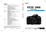
EOS D60
SERVICE
MANUAL
C12-6011
Technical Documents
Application
This CD-ROM is issued by Canon Inc. for qualified persons to learn technical theory and
product repair. This CD-ROM covers all localities where the products are sold. For this
reason, there may be information in this CD-ROM that does not apply to the product sold in
your locality.
The following paragraph does not apply to any countries where such provisions are
inconsistent with local law.
Trademarks
The product names and company names described in this CD-ROM are the registered
trademarks of the individual companies.
Copyright
Canon Inc. retains the copyright to all data contained on this CD-ROM.
Reproduction, publication (including on the World Wide Web) alteration, translation into
another language, or other use of the data in whole or part, contained on this CD-ROM
without the written consent of Canon Inc., is prohibited.
PDF Files
This CD-ROM contains PDF files created using Adobe® Acrobat® 4.0J. PDF files can be
viewed using Adobe® Acrobat® Reader 4.0 or later.
Copyright © 2002 Canon Inc.
First published April, 2002
PREFACE
This manual contains information for servicing the product, and has the following
sections:
Part 1 General Information
Provides the basic information needed to understand the product.
(Operating instructions are not included. Refer to the products instruction book if
necessary.)
Part 2 Technical Information
Provides technical information about the mechanism and electronics of the
product.
Part 3 Repair Information
Provides information about ths tools and expendables required for disassembly,
reassembly, adjustment and measurement of the product, and their locations and
method of use.
Part 4 Electrical Adjustments
No electrical adjustments for this product.
Part 5 Parts Catalog
Part 6 Circuit Diagrams
Part 7 Software Information
Appendix
I
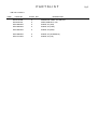
CONTENTS
Page
Part 1: General Information
1. FEATURES ............................................................................................1-1
1.1 Ultra-fine, high-image quality about 6.30 megapixel CMOS sensor...1-1
1.2 Retains EOS D30's Outstanding Features .....................................1-1
1.3 User Suggestions Incorporated for Better Basic Performance ......1-1
2. OVERVIEW ............................................................................................1-2
2.1 EOS D60 body ...............................................................................1-2
2.2 EOS D60 software .........................................................................1-5
3. SPECIFICATIONS .................................................................................1-7
4. NOMENCLATURE .................................................................................1-26
5. VISUAL INDICATORS ...........................................................................1-27
5.1 Viewfinder Information ...................................................................1-27
5.2 LCD Panel Information ...................................................................1-28
5.3 LCD Monitor Display ......................................................................1-29
6. CUSTOM FUNCTION ............................................................................1-30
7. DIMENSIONS & PROGRAM DIAGRAMS .............................................1-31
7.1 Dimensions ....................................................................................1-31
7.2 Program Diagrams .........................................................................1-32
8. SYSTEM ACCESSORIES COMBATIBILLITY TABLES ........................1-34
8.1 System Accessories .......................................................................1-34
8.2 EOS System Accessories ..............................................................1-35
9. COMPARISON WITH OTHER MODELS ...............................................1-37
9.1 Comparison with Competing Models .............................................1-37
9.2 Comparison with EOS Cameras ....................................................1-38
10. OPERATION CAUTIONS .....................................................................1-40
10.1 Operaton Cautions .......................................................................1-40
10.2 Built-in Flash and EF Lens Compatibility ......................................1-41
II
Part 2: Technical Information
1.TECHNICAL DESCRIPTION ..................................................................2-1
1.1 CMOS sensor imaging element .....................................................2-1
1.2 Image recording and processing ....................................................2-4
1.3 AF system ......................................................................................2-6
1.4 Viewfinder ......................................................................................2-7
1.5 Exposure control mechanism .........................................................2-8
1.6 Drive ...............................................................................................2-8
1.7 LCD panel ......................................................................................2-9
1.8 Built-in flash ....................................................................................2-9
1.9 Basic operation concept and LCD panel display ............................2-9
1.10 Improved firmware .......................................................................2-11
1.11 Internal construction .....................................................................2-12
1.12 Custom Functions ........................................................................2-12
1.13 Compatibility with accessories .....................................................2-13
2. FUNCTION OF MAJOR CIRCUIT BOARDS .........................................2-15
2.1 Description of Major Circuit Boards ................................................2-15
3. SWITCHES AND THEIR FUNCTIONS ..................................................2-18
4. CIRCUIT OUTLINES ..............................................................................2-21
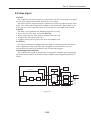
4.1 Power Supply Control ....................................................................2-21
4.2 Main System ..................................................................................2-22
4.3 Camera System .............................................................................2-22
4.4 Video Signal ...................................................................................2-23
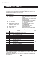
5. ERROR CODE DISPLAY .......................................................................2-24
III
Part 3: Repair Information
1. PREPARATION FOR REPAIR ...............................................................3-1
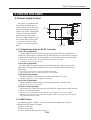
1.1 Flash High Voltage Circuit Precaution ...........................................3-1
1.2 Power Consumption .......................................................................3-1
1.3 Tools and Expendables List ...........................................................3-2
1.4 Locally Fabricated Tools ................................................................3-3
1.5 Body Serial Number Position .........................................................3-4
1.6 Flexible Connectors .......................................................................3-4
2. DISASSEMBLY/ASSEMBLY ..................................................................3-5
2.1 Terminal Cover and Front Cover ....................................................3-5
2.2 Main Battery Cover, Grip and Bottom Cover ..................................3-6
2.3 Rear Cover .....................................................................................3-7
2.4 Top Cover, Flash Cover and OLC Window ....................................3-8
2.5 Rear Frame, Eyepiece Cover and Strap Holder ............................3-9
2.6 OLC, TFT PCB and TFT LCD ........................................................3-10
2.7 D PCB, CF FPC and Right Cover ..................................................3-12
2.8 CMOS Sensor and A PCB .............................................................3-13
2.9 DC/DC PCB, MD FPC, AF Auxiliary Indicator part .......................3-15
2.10 Left Body Unit ...............................................................................3-16
2.11 FRONT FPC and Front Panel Unit ...............................................3-17
2.12 Front Body ....................................................................................3-18
2.13 Eyepiece Lens and SPC Unit .......................................................3-19
2.14 Shutter Unit and C-MAIN PCB. ....................................................3-20
2.15 ILC and AF Unit ............................................................................3-21
2.16 Focusing Screen, Lens Mount and Lens Mount Contact Assembly...3-22
2.17 Rear Cover Block .........................................................................3-23
2.18 Screw List......................................................................................3-24
3. MECHANICAL ADJUSTMENT ...............................................................3-25
3.1 Main Mirror and Sub Mirror Adjustment .........................................3-25
3.2 AF Sensor Position Setting ............................................................3-25
3.3 Flange to Focal Plane Distance (FFD) Adjustment.........................3-26
3.4 Finder Focus Adjustment ...............................................................3-28
4. SIMPLIFIED MEASUREMENT METHOD OF EXPOSURE AND SHUTTER ...3-30
IV
Part 4: Electrical Adjustments
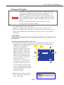
1. ELECTRICAL ADJUSTMENTS ..............................................................4-1
1.1 Cautions .........................................................................................4-1
1.2 Installation Procedure ....................................................................4-2
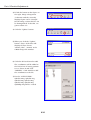
1.3 Description of Camera's Electrical Adjustments..............................4-5
1.4 Required Electrical Adjustment Chart Upon Camera Disassembly ...4-6
1.5 Checking and Adjusting the AE, E-TTL, and Exposure ................4-7
1.6 Digital Section Adjustment and Standard Data Generation ...........4-10
1.7 Maintenance of Light Source .........................................................4-12
1.8 Imager File Update .........................................................................4-13
1.9 AF Focus Adjustment Procedure ...................................................4-16
1.10 Checking the Version ...................................................................4-18
1.11 SPC Positioning Adjustment ........................................................4-19
1.12 Color Matrix Adjustment ...............................................................4-20
1.13 Storing Settings and Adjustment Data .........................................4-22
1.14 Defragmenting the Adjustment Area ............................................4-24
Part 5: Parts Catalog
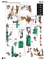
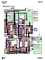
Part 6: Circuit Diagrams
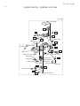
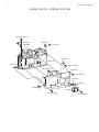
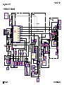
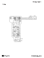
1. WIRING DIAGRAM
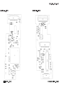
2. BLOCK DIAGRAM
2-1. GENERAL
2-2. POWER SUPPLY
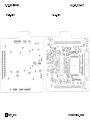
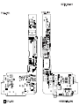
3. P.C.B DIAGRAM
A P.C.B._SIDE A
A P.C.B._SIDE B
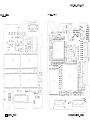
C-MAIN P.C.B._SIDE A
C-MAIN P.C.B._SIDE B
D P.C.B._SIDE A
D P.C.B._SIDE B
TFT. P.C.B._SIDE A
TFT. P.C.B._SIDE B
EL F.P.C
ILC F.P.C
Part 7: Software Information
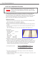
1. GENERAL INFORMATION ....................................................................7-1
1.1 Product Overview ...........................................................................7-1
1.2 Compatible Operating Systems and Computer Environments .......7-2
1.3 Connecting the EOS D60 to the Computer ....................................7-2
1.4 EOS D60 Software Overview .........................................................7-3
V
Appendix
AGC Chart
AF Standard Chart (Horizontal)
AF Standard Chart (Vertical)
SPC Positioning Mask
3D Chart
VI
Part 1
General
Information
Part 1: General Information
1. FEATURES
1.1 Ultra-fine, high-image quality about 6.30 megapixel CMOS
sensor
• Newly developed, large, single-plate CMOS sensor of 22.7 x 15.1 mm effective size
• Effective pixels: Approx. 6.30 megapixels (6.52 megapixels total)
• Effective angle of view: Equivalent to 1.6x normal EF lens focal length
1.2 Retains EOS D30's Outstanding Features
• Continuous shooting speed of approx. 3 fps and maximum burst of 8 shots
• Same features, performance, operation ease, and shooting-priority concept as
the EOS D30
• Completely compatible with all Canon EF lenses
• Compatible with EOS D30 system accessories
• Three AF points and three AF modes (ONE SHOT, AI SERVO, AI FOCUS)
• 35-zone AE sensor, three metering modes (evaluative metering, partial,
centerweighted average)
• Eleven shooting modes (8 programmed AE modes, Tv, Av, M)
• 1/4000 sec. - 30 sec., bulb, X-sync at 1/200 sec.
• ISO speed: 100, 200, 400, 800, 1000
• E-TTL autoflash (with built-in flash and EX-series Speedlites)
• Built-in flash: Guide No. 12 (at ISO 100 in meters)
• Single/continuous shooting, self-timer
• Dioptric adjustment from -3 dpt. to +1 dpt.
• Compatible with CF card Type I/II
• Seven white balance modes
• Menu settings, Custom Functions
• Noise reduction during long exposures
• 1.8-in. TFT liquid-crystal monitor
• USB interface, video output
• Dimensions: 149.5×106.5×75 mm / 5.9×4.2×3.0 in, weight 780 g /27.5 ounce
• Bundled software for image manipulation, etc.
1.3 User Suggestions Incorporated for Better Basic Performance
•
•
•
•
•
•
Superimposed display for AF points
LCD panel (EL) illumination
Better AF performance in low light (EOS D30: EV2 - EV18 → EOS D60: EV0.5 - EV18)
Shorter and more stable shutter release time lag
Improved metering table for stable exposure control
Additional viewfinder information (Flash exposure compensation icon,
maximum burst indicator, and remaining shots counter added.)
• Processing parameters settable with the on-screen menu
• More menu functions and Custom Functions
• Shorter startup time from power-off
1-1
Part 1: General Information
2. OVERVIEW
2.1 EOS D60 body
While retaining the best features of the EOS D30, the EOS D60 has many more
pixels and new and improved specifications desired by users. The EOS D60's
improvements over the EOS D30 are outlined below. (All specifications not
mentioned below are the same as the EOS D30.)
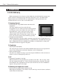
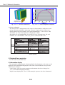
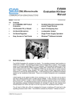
1) Imaging element
• Newly developed, large CMOS sensor with about 6.30
megapixels
The large CMOS sensor has 6.30 effective
megapixels (out of a total of about 6.52 megapixels),
an effective sensor size of 22.7×15.1 mm (same as
the EOS D30's), aspect ratio (2:3), large single
CMOS sensor and separate filters for the three
primary RGB colors. It boosts the camera to the top
of its class for fine image detail and image quality.
Fig. 1-1 CMOS sensor
• Red ghost countermeasures
With the EOS D30, red ghost outline sometimes appeared near a bright light source
or at a symmetrical point in the field. As a countermeasure, the EOS D60's low-pass
filter configuration has been modified. The IR filter is a hybrid with a coating and
absorption function to suppress red ghost.
2) Viewfinder
• Superimposed (SI) display
The same SI optics found in the EOS 55/ELAN II/50 has been incorporated in
front of the pentaprism so that the AF points can be illuminated.
• Easier manual focusing
The New Laser Matte focusing screen has improved diffusion characteristics to
make it easier to distinguish peak focus.
3) AF
• Improved AF operation in low light
With the EOS D30, AF operation was possible in the EV 2 - EV 18 range. This
has been improved to EV 0.5 - EV 18 (normal temperature with ISO 100) with
the EOS D60. The algorithm for the AF-assist beam has also been modified to
improve AF operation in low light.
4) Metering and exposure control
• Shorter and more stable shutter release time lag
With improved firmware, the shutter release time lag is much shorter and more
stable than the EOS D30's.
1-2
Part 1: General Information
• Improved metering algorithm
Some users complained about how the meter reading changed even after the
picture was slightly recomposed. To address this problem, the α compensation
steps has been made finer (1/4f instead of 1/2f).
5) Drive
• Continuous shooting speed: Approx. 3 fps, Maximum burst: 8 frames
The EOS D30's maximum burst during continuous shooting in the Large/Fine
mode is approx. 8 shots. With other recording/compression modes, this
maximum burst increases or decreases.
The EOS D60 has a larger buffer memory to better handle the image's larger
data resulting from the high pixel count. The maximum burst of 8 shots can be
attained regardless of the image-recording format and ISO speed. The maximum
burst countdown is also displayed at the bottom of the viewfinder. With the EOS
D30, the maximum burst was 3 shots in the RAW mode.
With the EOS D60, it is now 8 shots. Thus, during continuous shooting, the
RAW mode has become more practical.
6) Image-recording format
• Middle/Fine and Middle/Normal added
• Extracting JPEG-Middle/Fine files from RAW files
During RAW mode shooting, a JPEG-Middle/Fine file is also simultaneously
recorded within the .crw file. The JPEG-Middle/Fine file can be extracted from
the RAW file and saved (.jpg) with the dedicated driver (provided).
• File size and compression rate settable in Programmed Image Control modes
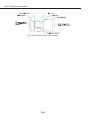
7) Information display
• More viewfinder information provided
At the bottom of the viewfinder, the
following information has been added: 1.
Flash exposure compensation, 2.
Maximum burst during continuous
shooting, 3. Shots remaining. (Since SI
display is provided, there is no AF point
icons.)
1-3
Fig. 1-2 Comparison of viewfinder
information.
Part 1: General Information
• LCD panel illumination provided
The LCD panel now has EL backlight illumination (bluish-green). When it is
turned on with the on-screen menu (off by default), the illumination turns on
when you press the SET button.
• LCD monitor easier to read
The TFT monitor's sheet material has been changed so that the visibility at
higher angles (over 40 deg. vertically and horizontally) is brighter.
8) Menu functions
• Processing parameters settable with the camera
With the camera's on-screen menus, you can set processing parameters
(contrast, sharpness, color saturation, and the newly added color tone). You can
set each parameter to one of three settings (-, 0, +). Up to three sets of
parameter settings can be set and registered. (The parameters cannot be saved
with the bundled software.)
• New menu items added
• Image-recording quality/Compression rate: Middle/Fine, Middle/Normal
• LCD panel illumination: 0: Off, 1: On
• C.Fn setting cancel: Cancel/OK
• Firmware Ver. 1.0.0
9) Custom Functions
• New Custom Functions and modified settings
New Custom Functions
Modified Settings
Canceled item
C.Fn-1: Noise reduction during long exposures, 0: Off, 1: On
10) Design
The EOS D60's exterior design differs from the EOS D30 as follows:
• The main switch has a different shape (for easier operation).
• The color on the top of the mode dial is metallic titanium instead of black.
• The PC terminal and remote control terminal now share a joint rubber cap
instead of a separate cap for each terminal.
• The shape of the interface-terminal cover (DIGITAL terminal, VIDEO terminal)
is different.
1-4
Part 1: General Information
• A "DIGITAL" nameplate is added on the lower right of the camera front.
11) Power source
• Shorter startup time from power off
During the camera's auto power off, information about the recording medium's
usable area is saved in the camera's memory. Therefore, when you turn on the
camera again, the startup time is faster. This feature is especially effective for
MicroDrive storage devices.
• Excellent shooting performance
About 490 shots can be captured under the following conditions: fully charged
batteries, 2-sec. image playback, Large/Fine recording format, and 50% flash
use.
12) Dimensions and weight
Dimensions: 149.5 (W)× 106.5 (H)×75 (D) mm/5.9 (W)×4.2 (H)×3.0 (D) in
(identical to EOS D30), Weight: 780 g/27.5 ounce
2.2 EOS D60 software
Besides Adobe Photoshop 5.0 LE, the following software for Windows and
Macintosh will be bundled with the camera.
The software will be compatible with Windows 98 SE/Me/2000/XP and Mac OS
8.6 to 9.2.
1) Windows software
• TWAIN Driver
• This TWAIN-standard driver operates under Windows 98SE or 2000. It
enables you to view and download images and process RAW images stored in
the camera's CF card while the camera is connected to a personal computer
with the interface cable (provided).
• The major specifications are the same as the EOS-1D's TWAIN Driver for
Camera.
* This driver can start up only within a TWAIN-compatible program (such as
Photoshop LE).
• WIA Driver
• Compatible with Microsoft's WIA (Windows Image Acquisition) standard, this
driver works with Windows Me and XP.
• When connected to a personal computer with the interface cable (provided),
the camera can be mounted on the computer's Explorer desktop as if it were a
removable disk. Explorer can then be used to download images without using
any other driver.
• RAW Image Converter
• Utility program that enables you to process RAW images saved on any drive.
• Compatible with RAW images captured by the EOS D60, EOS-1D, and EOS
D30.
1-5
Part 1: General Information
• Zoom Browser EX
• Image management utility program bundled with the latest PowerShot-series
cameras. It has the added feature of processing EOS D60 RAW images. Only
the Japanese version enables CIG (Canon Image Gateway) access.
• Photo Record
• Layout printing utility program. It works with ZoomBrowser EX for printing
with an automatic layout, printing on borderless perforated paper with Canon
BJ printers, borderless (on all four sides) printing, etc.
• Remote Capture
• Utility program that enables the camera to be controlled with a personal
computer. The captured image can be received directly by the personal
computer. Besides single-frame shooting, timer and interval timer operations
are possible.
• PhotoStitch
• Utility program for compositing multiple images into a single image. Images
can be stitched together very precisely to create panorama photos, etc.
2) Macintosh software
• Photoshop Plug-in Module
• This has the same features as the TWAIN Driver for Windows.
• USB Mounter
• Utility program that enables the camera to be mounted on the Macintosh
desktop as if it were a removable disk while the EOS D60 is connected to the
Mac with the interface cable (provided). Images captured by the EOS D60 can
then be easily copied to the Mac.
• RAW Image Converter
• Macintosh version of RAW Image Converter for Windows.
• Image Browser
• This image management utility program has the same features as Zoom
Browser EX for Windows.
• Regarding the printing function, it has the same features as PhotoRecord for
Windows which is a printing layout program.
• Remote Capture
• Macintosh version of Remote Capture for Windows.
• PhotoStitch
• Macintosh version of PhotoStitch for Windows.
1-6
Part 1: General Information
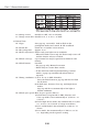
3. SPECIFICATIONS
1.Type
1-1 Type:
1-2
1-3
1-4
1-5
1-6
Digital AF/AE single-lens reflex camera with focal-plane
shutter (vertical travel) and built-in flash.
CMOS sensor for direct imaging
Image size:
22.7×15.1 mm
Compatible lenses: Canon EF lenses (Due to max. aperture metering,
stopped-down shooting not possible.)
Lens mount:
Canon EF mount
Lens restrictions: None
Lens focal length: Equivalent to 1.6x the normal lens focal length
2. Imaging Element
2-1 Type:
2-2
2-3
2-4
2-5
2-6
2-7
2-8
2-9
Image size:
Total pixels:
Effective pixels:
Pixel unit:
Aspect ratio:
Color filter type:
Low-pass filter:
Cleaning mode:
High-sensitivity, high-resolution, single-plate, color
CMOS
22.7 mm×15.1 mm (APS C size)
About 6.52 megapixels: 3152 (H)×2068 (V) pixels
About 6.30 megapixels: 3072 (H)×2048 (V) pixels
7.4 µm square
2:3 (Vertical:Horizontal)
Three separate RGB primary color filters
Fixed in front of the imaging element
Provided with C.Fn-13-1
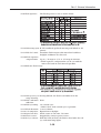
3. Recording System
3-1 Recording medium: Compact Flash (CF) card
3-2 Recording format: In accordance with the CF card standard
* Formatting possible with the EOS D60.
* The formatted CF card's volume name will be “EOSDigital.”
3-3 Image recording
format:
3-4 RAW+JPEG
simultaneous recording: A JPEG-Middle/Fine file is also simultaneously
recorded within the .crw file. The JPEG-Middle/Fine file
can be extracted from the RAW file and saved (.jpg) with
the dedicated driver (provided).
1-7
Part 1: General Information
3-5 File size and recording capacity:
4. Information Recorded
4-1 Image recording format:
4-2 Folder setting:
4-3 Image file name:
(1) Shutter speed (2) Aperture (3) Exposure compensation amount
(4) ISO speed (5) Image-recording format (6) Shooting mode
(7) White balance (8) Metering mode (9) AEB (10) Flash mode
(11) Flash exposure compensation (12) AF mode
(13) Focal length used (14) Erase protection (15) Date (16) Time
(17) Folder name (18) File name/number (19) Active AF point
(20) Selected AF points (21) Camera owner (22) Body No.
(23) Drive mode (24) Flash sync timing (25) Custom Functions
(26) Processing parameters (27) Red-eye reduction
Complies with the Design rule for Camera File (DCF)
standards.
Automatic
The file name consists of file name, file number, and
extension:
* The file number setting set with the on-screen menu
will apply to the number.
* The file name and extension for RAW images will be
CRW_ and CRW respectively.
* The extension for thumbnail images in the index
display will be THM.
* Conforms with DCF File standards.
4-4 File No.:
The following two types of file numbers can be set:
The captured images are automatically assigned a file
number from 0001 to 9900. And each folder is assigned
a number from 100 to 998.
(1) Serial numbering
* The serial numbering of captured images will continue
even after you replace the camera's CF card.
1-8
Part 1: General Information
(2) Auto reset
* When you replace the camera's CF card, the
numbering will be reset, starting with 100-0001. If the
new CF card already contains images, the numbering
will continue from the last recorded image in the CF
card.
4-5 Processing parameters: Besides the standard processing parameters applied by
the camera automatically during image recording, the
user can create and register up to three sets of
parameters (contrast, sharpness, color saturation, color
tone).
* The parameters can be set with the EOS D60's onscreen menu (not with the dedicated software).
5. Disk Drive
5-1 Type:
5-2 Slots:
5-3 CF card access indicator:
5-4 Read error warning:
Accepts CF card Types I and II; has cover
One
Blinking access lamp
The respective error warning is displayed on the LCD
panel and in the viewfinder.
* Shutter release also locks.
5-5 CF card format:
Enabled with the on-screen menu.
5-6 Misloading prevention Provided
mechanism:
6. White Balance
6-1 Type:
6-2 Modes:
Auto white balance using the imaging element.
The LCD panel indicates the white balance mode.
6-3 White balance bracketing: Not provided
7. Viewfinder
7-1 Type:
SLR-type, eye-level viewfinder (with fixed pentaprism
but no condenser lens)
7-2 Focusing screen: Fixed, New Laser Matte screen
7-3 Dioptric adjustment: Adjustable from -3.0 dpt to +1.0 dpt.
1-9
Part 1: General Information
7-4
7-5
7-6
7-7
Eyepoint:
20 mm
Coverage:
95% vertically and horizontally (For the effective pixels)
Magnification:
0.88X. (with 50mm lens at infinity, -1 dpt)
Viewfinder information:(1) On the screen
1) AF points
2) Partial metering circle (6.1 mm dia., approx. 9.5%)
(2) Below the screen
• Numerals and letters displayed by 7-segment LCD
(yellowish-green)
3) Shutter speed (If there is a camera shake or the
shutter speed is unsuitable, it blinks at 2 Hz as a
warning.), bulb, FEL indicator
4) Aperture (If unsuitable, it blinks at 2 Hz as a
warning.)
5) Max. burst during continuous shooting: Max. 8
6) Shots remaining (Displayed when the CF card has
room for 8 or fewer images)
7) Busy (buSY)
8) CF card full warning (FuLL CF)
9) CF card error warning (Err CF)
10) No CF card warning (with C.Fn-15-1/CF)
• LCD mask (yellowish-green) display
11) AE lock/FE lock icon, AEB in-progress indicator
(blinks at 2 Hz)
12) Exposure level (+/-2 stops in 1/3- or 1/2-stop
increments)
12)-1: AE exposure compensation amount, 12)-2:
Manual exposure level,
12)-3: AEB level, 12)-4: Red-eye reduction lamp
on time display,
12)-5: Flash exposure compensation amount
13) Flash exposure compensation icon
14) Flash icon on: Flash ready
Flash icon blinking: Flash exposure beyond range
warning during FE lock (2 Hz)
15) High-speed sync (FP flash)
16) AF focus confirmation light (blinks at 2 Hz when
focus cannot be achieved), MF focus confirmation
light
* The viewfinder information display cannot be turned
off.
7-8 Mirror:
Quick-return half mirror (Transmittance:reflectance
ratio of 40:60)
7-9 Viewfinder blackout time: Approx. 300 ms at 1/60 sec. or faster shutter speeds.
1-10
Part 1: General Information
7-10 Mirror lockup:
7-11
7-12
7-13
7-14
Enabled with C.Fn-3-1
* Mirror locks up when the shutter button is pressed
completely (SW-2). The picture is taken when the
shutter button is let go and pressed completely again.
Mirror lockup duration: Max. 30 sec. after which the
mirror returns.
Mirror cut-off:
No cut-off with lenses up to EF 600mm f/4
Depth-of-field preview: Enabled with depth-of-field preview button
* Enabled in the Creative Zone modes (disabled in Full
Auto and Programmed Image Control modes).
* With Speedlite 550EX, 420EX, MR-14EX, or MT24EX, pressing the depth-of-field preview button fires
a modeling flash.
Eyepiece shutter: None (Eyepiece cover provided on strap)
Misc.:
Eyecup Eb provided
*Angle Finder C, Angle Finder B, Magnifier S, Eyepiece
Extender EP-EX15 attachable to eyepiece.
8. Autofocus
8-1 Type:
8-2 AF points:
8-3 Focusing modes:
Multi-BASIS, TTL-CT-SIR (TTL secondary phase
difference detection)
Three
(1) Autofocus
Switchable between the following three modes:
1) One-Shot AF
When focus is achieved, the autofocus operation
stops and locks (AF lock).
* AF-priority (The shutter can be released only when
focus is achieved.)
* During evaluative metering, AE lock is set when
focus is achieved.
* In the partial metering and centerweighted average
metering modes, exposure metering continues in
real-time until the shutter is released.
* With applicable USM lenses, electronic ring manual
focusing can be used after focus is achieved with
One-Shot AF or if focus is cannot be achieved with
One-Shot AF.
* Set automatically in the Portrait, Landscape, Closeup, and Night Scene modes.
2) Predictive AI Servo AF
Tracks subject movement and focuses continuously
until the start of exposure.
* Single shot or 1st shot during continuous shooting:
Shutter-priority (in Creative Zone modes)
* Single shot or 1st shot during continuous shooting:
AF-priority (in Full Auto and Sports modes)
1-11
Part 1: General Information
8-4 AF point display:
* From 2nd shot onward during continuous shooting:
AF-priority
* Focus confirmation light provided. No focus
confirmation beeper.
* If focusing is impossible, the • indicator blinks at 2
Hz.
3) One-Shot/Predictive AI Servo AF switching
For still subjects: When focus is achieved, AF
operation stops (AF lock).
For moving subjects: Subject tracking and focusing
continues until the start of
exposure.
* With applicable USM lenses, electronic ring manual
focusing can be used after focus is achieved with
One-Shot AF or if focus is cannot be achieved with
One-Shot AF.
(2) Manual focusing
After the lens focus mode is set to MF (or M), manual
focusing is enabled with the focusing ring.
* During automatic AF point selection, focus aid is
provided for the three AF points. During manual AF
point selection, focus aid is provided for the selected
AF point.
* An focus confirmation light is provided. No focus
confirmation beeper.
The selected AF point is indicated by: (1) Superimposed
display in the viewfinder, (2) Current selected AF point
indicated on the LCD panel.
(1) Automatic selection or (2) Manual selection
8-5 AF point selection
method:
8-6 AF point switching: P, Tv, Av, M: Manual and automatic AF point selection
enabled.
Other shooting modes: Automatic AF point selection is
set automatically.
8-7 AF point selection: Selectable with the Main Dial or Quick Control Dial.
(1) Automatic AF point selection
• In the One-Shot AF mode: Based on the subject
information obtained by the three AF points, the AF
point focusing the optimum (closest) subject is
selected automatically.
• In the AI Servo AF mode: At the start of focusing, one
of the three AF points must focus the subject. That
AF point then will continue to focus-track the
subject. If the subject moves away from the AF point,
focusing is attempted again by all three AF points.
(The focus-tracking cannot jump to another AF point.)
• In the AI FOCUS AF/ONE-SHOT AF mode: Based on
the subject information obtained by the three AF
1-12
Part 1: General Information
points, the AF point focusing the optimum subject is
selected automatically. If a moving subject is
detected, all three AF points are used to focus. When
one of the AF points detect a moving subject, it
switches to AI SERVO AF. Then the AF point tracking
the subject focuses the subject. If the tracked subject
moves away from the AF point, focusing is attempted
again by all three AF points. (The focus-tracking
cannot jump to another AF point.)
(2) Manual AF point selection
One or three AF points can be selected for focusing.
8-8 AF activation:
AF is activated by pressing the shutter button halfway
(SW-1)
8-9 AF operation speed: Same as EOS D30
8-10 Focus confirmation Superimposed AF point displayed in viewfinder and
indication:
focus confirmation beeper
* The focus confirmation beeper can be enabled or
disabled in all the shooting modes.
* With automatic AF point selection and the ONE-SHOT
AF mode, the active AF point lights in red.
* With automatic AF point selection and the AI SERVO
AF mode, there is no superimposed AF point
displayed.
8-11 AF precision:
Same as the EOS 650's
8-12 AF working range: EV 0.5-18 (at normal temperature and ISO 100, with
the standard chart)
8-13 AF-assist beam: (1) Beam emission: Lamp
Effective range: Approx. 3.8 m (at center), beam
coverage: 28mm (135 equivalent) lens angle covered
(2) Conditions for emission: Emitted automatically
under low light (EV 4 or lower at ISO 100)
* Emitted in shooting modes except Landscape and
Sports.
* Emission can be disabled with C.Fn-5 (including
external Speedlite).
(3) Emissions: 6 times in three bursts
* Emission stops when focus is achieved.
(4) Light source: Halogen krypton lamp
(5) With EX-, EZ-, and E-series Speedlites
• With 550EX, 540EZ, and ST-E2: The external
Speedlite's AF-assist light will be emitted regardless
of AF point selection mode (automatic or manual).
• With other EOS-dedicated Speedlites: When the
center AF point has been selected, the external
Speedlite's AF-assist light will be emitted. If a
peripheral AF point is selected, the camera's AFassist light will be emitted.
1-13
Part 1: General Information
9. Exposure Control
9-1 Type:
TTL full aperture metering with 35-zone SPC. Three
metering modes provided:
1) Evaluative metering
2) Partial metering at center (approx. 9.5% of
viewfinder)
3) Centerweighted average metering
* In Full Auto and Programmed Image Control modes: 1)
is set automatically.
* (2) and 3) cannot be set.)
* In the Creative Zone modes, 1), 2), or 3) can be set.
9-2 Shooting modes: The following AE modes and manual can be set:
1) Intelligent Program AE (shiftable)
2) Shutter-priority AE (No safety shift)
3) Aperture-priority AE (No safety shift)
4) Depth-of-field AE (A-DEP, shiftable)
5) Full Auto (Intelligent Program AE/non-shiftable)
6) Programmed Image Control modes (5)
6) Portrait, Landscape, Close-up, Sports, Night Scene
7) Manual
8) E-TTL autoflash program AE
8) High-speed flash (FP flash), FE lock
* No A-TTL/TTL autoflash program AE
9-3 Metering range:
EV 2-20 (at normal temperature with 50mm f/1.4 lens
at ISO 100)
9-4 Exposure beyond LCD digital display blinks at 2 Hz on the LCD panel and
range warning:
in the viewfinder.
9-5 Exposure metering: Activated when shutter button is pressed halfway (SW-1
ON)
* Metering remains active for 4 sec. after the halfwaydepressed shutter button is let go.
9-6 ISO Speeds:
The following ISO speeds are selectable with the onscreen menu:
1) 100 (Default), 2) 200, 3) 400, 4) 800, 5) 1000
9-7 Exposure Compensation: (1) AEB (Auto Exposure Bracketing)
1) Compatible shooting modes: See the table below (at
4) ) for the shooting modes which enable AEB with the
on-screen menu.
* During AEB: The AEB icon on the LCD panel blinks,
and the *mark and AEB level blinks in the viewfinder.
2) Bracketing range: Up to +/- 2 stops in 1/2- or 1/3stop increments
3) Bracketing sequence: Standard exposure, decreased
exposure, and increased exposure
* Taken in accordance with the drive mode (single or
continuous).
1-14
Part 1: General Information
* If the self-timer is used, the three bracketed shots
will be exposed successively after the 10-sec. selftimer delay.
* With C.Fn-7, the bracketing sequence can be
changed or AEB can be set to continue even after
the three bracketed shots are taken.
4) Bracketing factor: See the bracketing factor used for
the respective shooting mode below.
5) AEB cancellation: Set the AEB amount to 0.
6) AEB automatic cancellation: Canceled by any of the
following operations: Main switch off, lens changed,
flash ready, battery replaced, or CF card replaced.
* AEB cannot be set in the Full Auto and Programmed
Image Control modes.
(2) Manual exposure compensation
1) Compatible shooting modes: See the table below for
the shooting modes which enable manual exposure
compensation.
2) Bracketing range: Up to +/- 2 stops in 1/2- or 1/3stop increments
3) Bracketing factor: See the bracketing factor used for
the respective shooting mode below.
4) Exposure compensation cancellation: Set the
exposure compensation amount to 0.
* Exposure compensation cannot be set in the Full
Auto and Programmed Image Control modes.
* If both AEB and manual exposure compensation are
set, the AEB amount will be shifted by the exposure
compensation amount.
(3) Flash exposure compensation
1) Compatible flash: Built-in flash and EX-series
Speedlites
2) Method: Flash exposure compensation button
3) Exposure compensation: Up to +/- 2 stops in 1/2- or
1/3-stop increments
1-15
Part 1: General Information
9-8 AE Lock:
9-9 Multiple exposures:
4) Flash exposure compensation cancellation: Set the
flash exposure compensation amount to 0.
* If flash exposure compensation has been set with
the external Speedlite, the external Speedlite's flash
exposure compensation will override the camera's
flash exposure compensation setting.
* Flash exposure compensation cannot be set in the
Full Auto and Programmed Image Control modes.
* The flash exposure compensation icon in the
viewfinder lights.
(1) Auto AE lock
* In the One-Shot AF mode with evaluative metering, AE
lock takes effect when focus is achieved.
(2) AE lock button
* Sets AE lock at any time.
* AE lock button does not work in the Full Auto and
Programmed Image Control modes.
* Regardless of the metering mode, center partial
metering will be used.
* During AE lock, pressing the AE lock button again
renews the AE lock.
* When the built-in flash or an external Speedlite is
used, the AE lock button works as an FE lock button.
Not possible
10. Shutter
10-1 Type:
Vertical-travel, mechanical, focal-plane shutter with all
speeds electronically-controlled
* Mechanical shutter: Both curtains have dedicated
magnet control. (Curtain speed: 2.9 ms/15.0mm)
10-2 Shutter speeds: 1/4000 to 30 sec. (1/3- and 1/2-stop increments),
bulb, X-sync at 1/200 sec.
* For bulb exposures, the elapsed exposure time is
displayed on the LCD panel.
10-3 Shutter release: Soft-touch electromagnetic release (No cable-release
socket)
10-4 Shutter-release time lag: Stop-down by up to 4.5 stops from maximum aperture
and excluding AF operation time:
(1) During SW-1 ON, time lag between SW-2 ON and
start of exposure: 100 ms
(2) Time lag between simultaneous SW-1/SW-2 ON and
start of exposure: 240 ms
10-5 Long exposure
None
noise reduction:
10-6 Self-timer:
Electronically-controlled 10-sec. delay
* Operates in all shooting modes.
1-16
Part 1: General Information
* After starting, the self-timer is cancelable by pressing
the drive button, turning the mode dial, pressing the
flash button, or changing the lens.
* After focus is achieved, self-timer starts when the
shutter button is pressed fully (SW-2). (In the AI
SERVO AF/MF mode, self-timer starts immediately at
SW-2.)
* With C.Fn-3-1, the self-timer delay can be set to 2 sec.
instead.
10-7 Self-timer indicator: Red-eye reduction lamp (blinks at 2 Hz for the first 8
sec., then lights for the remaining 2 sec.)
LCD panel (Frame counter counts down from 10 to 1
sec.)
Beeper (beeps at 2 Hz for the first 8 sec., then beeps at
8 Hz for the remaining 2 sec.)
* The beeper sounds only if it has been enabled with the
on-screen menu.
10-8 Camera shake warning: Provided in Full Auto and Programmed Image Control
modes.
* If the shutter speed (Tv-auto) is 0 to 0.5 stops slower
than the reciprocal of the lens focal length ×1.25, the
shutter speed display blinks at 2 Hz.
11. Drive
11-1 Drive modes:
(1) Single frame (2) Continuous (3) Self-timer (10 sec.)
* Creative Zone modes: Settable with the drive mode
button.
* Full Auto and Programmed Image Control modes:
Single frame or continuous set automatically
depending on the shooting mode.
11-2 Continuous shooting: Continuous shooting with images recorded in the builtin buffer memory.
* When the buffer memory becomes full, further
shooting is disabled until one image is completely
transferred to the Compact Flash card.
* While no pictures are taken (SW-1 OFF), images
stored in the buffer memory are constantly transferred
to the Compact Flash card to free up the buffer
memory.
11-3 Continuous shooting speed: Approx. 3 fps (at 1/250 sec. or faster shutter speeds)
11-4 Maximum burst 8 shots
during continuous shooting:
11-5 Battery life:
With Battery Pack BP-511 (Approx. shots)
1-17
Part 1: General Information
11-6 Image review:
Settable to OFF, ON, or ON (Info).
11-7 Image review time: Settable to 2, 4, or 8 sec. or Hold.
12. Built-in Flash
12-1 Type:
12-2
12-3
12-4
12-5
12-6
12-7
12-8
Auto pop-up, retractable, built-in flash in the
pentaprism with serial control, E-TTL autoflash
Guide No.:
Guide No. 12 (at ISO 100 in meters)
Recycling time:
Approx. 3 sec.
Flash ready indicator: Flash-ready icon lights on in viewfinder
* When the flash is not ready, the flash-ready icon is off
and the shutter release is locked.
Flash coverage:
Up to 18mm lens angle (equivalent to 28mm in 135
format)
Flash button:
Provided
* For pop-up only. Manual retraction.
* Works only in Creative Zone modes.
* In the Full Auto and Programmed Image Control
modes, it pops up automatically when flash is
required.
Firing conditions: (1) In P, Tv, Av, A-DEP, M modes:
Press the flash button to pop-up and fire the flash
for all shots.
(2) In Full Auto, Portrait, Close-up, and Night Scene
modes:
Pops up and fires automatically in low light or
backlit conditions.
Flash sync speed: Max. X-sync speed 1/200 sec.
1) In Full Auto, Program AE, A-DEP, Portrait, and
Close-up modes: Set automatically to 1/200 sec. to
1/60 sec.
2) In the Night Scene mode: Set automatically to 1/200
sec. to 2 sec. (in 1/2-and 1/3-stop increments)
3) In Tv and M modes: Set manually to 1/200 sec. or
slower.
4) In Av mode: Set automatically to 1/200 sec. to 30
sec. depending on the aperture setting.
1-18
Part 1: General Information
12-9 Flash aperture:
The flash aperture is set as shown below.
12-10 Flash metering system: E-TTL autoflash (preflash metering and linked to AF
points)
12-11 Flash level control: Automatic flash output reduction when backlit or
daylight conditions are detected.
12-12 Flash exposure
compensation: Up to +/-2 stops in 1/3- or 1/2-stop increments.
* Flash exposure compensation can be set with the
camera for built-in and external Speedlite.
12-13 Effective flash range:
12-14 Flash exposure beyond During FE lock, the flash icon blinks for 2 Hz.
range warning:
12-15 Flash confirmation None
indicator:
12-16 Flash-sync timing: 1st-curtain sync
* With C.Fn-8, 2nd-curtain sync is possible.
12-17 Flash duration: 1 ms or shorter
12-18 Color temperature: Equivalent to daylight
12-19 Optical axis offset: Flash center to lens axis: 73.8 mm
12-20 Power source:
Supplied by camera's power source.
12-21 Red-eye reduction: With the built-in flash, the flash is fired after the redeye reduction lamp lights.
1-19
Part 1: General Information
1) Type: Illumination by lamp (lamp also used for AFassist light)
2) Shooting modes: Operates in all modes except
Landscape and Sports.
3) Operation setting: On-screen menu
4) Conditions for illumination: Lights after focus is
achieved when the shutter button is pressed halfway
(SW-1) in the One-Shot AF or MF mode. (In the AI
SERVO AF mode, shutter-release priority takes effect
and red-eye reduction lamp lights immediately at
SW-1.)
5) Illumination duration: Under the conditions of 4,
lamp lights during SW-1 (with the self-timer, it lights
2 sec. before shutter release). Light level decreases
after 1.5 sec.
6) Lamp ON indicator: Exposure level display in
viewfinder (dot display sequence for the first 1.5 sec.)
7) Shutter-release lock: None (Shutter-release priority)
* The control condition above also apply when an
external Speedlite is used.
13. External Speedlite
13-1 Flash sync contacts: (1) Hot shoe: X-sync contacts
* Locking pin hole provided to prevent Speedlite
slippage.
(2) Lower side terminal: PC terminal (JIS B-type socket)
* Screw lock and shock protection feature provided on
the hot shoe.
13-2 Flash auto:
Enabled with the camera's Program AE mode.
(1) With EX-series Speedlites: E-TTL autoflash
1) Normal flash
When the flash is ready, the flash sync speed (1/60
sec. - 1/200 sec.) is set automatically. The camera's
E-TTL program automatically sets the flash aperture.
When the shutter button is pressed fully (SW-2), a
fixed-output preflash is fired right before the mirror
goes up. The AE sensor takes an available light
reading (before the preflash is fired) and a reflectedlight reading when the preflash is fired. The suitable
output of the main flash is then calculated, and the
main flash is fired. If an EX-series Speedlite is set for
high-speed sync (FP flash) and the light level exceeds
the lens’ minimum aperture, high-speed sync takes
effect automatically. When highspeed sync is set, the
icon lights in the viewfinder. Daylight sync (fill
flash) can also be controlled automatically.
2) FE lock
When an EX-series Speedlite is used and the flash is
1-20
Part 1: General Information
ready, the AE lock button functions as an FE lock
button. Pressing this button fires a preflash and the
AE sensor meters (by partial metering) the light
reflected off the main subject. The suitable flash
output is then calculated and stored in memory.
When the shutter button is pressed fully, the flash is
fired at the output stored in memory. If an EX-series
Speedlite is set for high-speed sync (FP flash) and the
light level exceeds the lens’ minimum aperture, highspeed sync takes effect automatically. When highspeed sync is set, the
icon lights in the viewfinder.
After the FE lock button is pressed and the flash is
ready, a preflash is fired and FE lock takes effect. If
the flash will be beyond the range (the flash output is
0.5 or more stops insufficient for obtaining a proper
flash exposure) the icon blinks at 2 Hz. Daylight
sync (fill flash) can also be controlled automatically.
* With the 550EX, MR-14EX, MT-24EX: Enables 3group (A, B, C) wireless control, flash ratio control
(A:B), FEB, and modeling flash (with flash ratio).
(2) With built-in flash: E-TTL autoflash
Specifications are the same as (1) above, except highspeed sync is not possible.
(3) With EZ-, E-, EG-, ML-, and TL-series Speedlites:
Autoflash not possible.
1) With the 540EZ, 430EZ, and 420EZ:
Compatible only in the manual (Multi) mode (ATTL/TTL autoflash modes will not work.).
• Set the camera to the manual (M) mode
(recommended).
• Set sync speed manually to 1/200 sec. or slower.
• Set the flash aperture manually to suit the subject
distance and brightness.
* Since the 300EZ does not have a manual flash
mode, it will be the same as 2) in (3).
2) With other EOS Speedlites:
Incompatible since they do not have a manual flash
mode. (Flash cannot be fired.)
* The 480EG can be fired by using the sync contacts.
(4) With other Speedlites:
1) With M-, T-, A-series Speedlites
Compatible in the manual flash mode or with
external flash metering.
• Set the camera to the manual (M) mode
(recommended).
• Set sync speed manually to 1/200 sec. or slower.
• Set the flash aperture manually to suit the subject
distance and brightness.
1-21
Part 1: General Information
2) With non-Canon flash units:
On-camera unit can synchronize at 1/200 sec. or
slower.
Studio flash can synchronize at 1/60 sec. or slower
(testing recommended).
13-3 Wireless flash:
Enabled with the 550EX, 420EX, MR-14EX, MT-24EX,
or ST-E2.
* Three-group (A, B, C) slave control, a flash ratio (A:B)
setting, FEB, and modeling flash (with flash ratio) are
enabled.
* The 420EX can function as a slave, while the MR14EX or MT-24EX serves as the master unit.
13-4 Flash exposure compensation: Settable with the camera or external Speedlite.
* Up to +/-2 stops in 1/3- or 1/2-stop increments.
* If flash exposure compensation is set with both the
camera and Speedlite, the Speedlite's setting will
override the camera's setting.
13-5 Flash Exposure Settable with the 550EX, MR-14EX, or MT-24EX.
Bracketing (FEB): * Not settable with the camera.
* When the flash fails to recycle fast enough during
continuous shooting with FEB, the shutter release
locks. After the shutter button is released from the
fully depressed position, AE metering takes effect
before the flash is ready.
13-6 Modeling flash:
With the 550EX, 420EX, MR-14EX, or MT-24EX, press
the depth-of-field preview button (fires at 70 Hz for 1
sec.).
14. LCD Monitor
14-1 Type:
14-2 Monitor size:
14-3 Pixels:
14-4 Coverage:
14-5 Brightness adjustment:
14-6 Refresh rate:
14-7 Angle adjustment:
14-8 Protective cover:
TFT color, liquid-crystal monitor
1.8 in.
Approx. 114,000 pixels
Approx. 100% (with effective pixels)
2-level (standard/brighter) adjustment provided.
Approx. 1/60 sec.
None
None
15. Playback
15-1 Image display format: (1) Single image, (2) Single image (Info.),
(3) 9-image index (4) Magnified, (5) Auto play
15-2 Display conditions: Images saved in DCF system.
* If the image is not in the DCF system, [?] is displayed
on the LCD monitor.
* Also applicable to thumbnail images (index display).
15-3 Highlight alert:
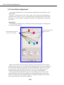
In the single image (Info.) display mode, the highlight
portions which do not contain image information will
blink.
1-22
Part 1: General Information
16. Information display
16-1 Display format:
(1) Standby mode
1) Auto power-off setting time, 2)Image review,
3) Image review time, 4) Processing parameters (when set),
5) Custom Function setting No.,
6) Flash exposure compensation amount, 7) AEB increments,
8) Shots remaining, 9) CF card space remaining, 10) ISO speed
(2) Playback/Single (INFO.)
1) File No., 2) Shooting mode, 3) Shutter speed, 4) Aperture,
5) Exposure compensation amount,
6) Flash exposure compensation amount (only when flash is used),
7) White balance, 8) Metering mode, 9) ISO speed,
10) Image No./Total images captured,
11) Image erase protection (when set),
12) File size/Compression rate, 13) Date, 14) Time, 15) Histogram
* If an image not in the DCF system is selected, [?] is
displayed on the LCD monitor.
* If an image that cannot be displayed is selected, [!] is
displayed on the LCD monitor.
* Information display does not work in the index display
mode and magnified display mode.
17. Protection/Deletion of Recorded Images
17-1 Protection:
A single image can be protected or unprotected.
17-2 Erase:
A single image or all images stored in a Compact Flash
card can be erased if they are unprotected.
* Protected images cannot be erased with the camera.
18. Menus
18-1 Description:
24 menus (8 shooting menus, 4 playback menus, 12
setup menus)
* See the list of menu items on page 33.
18-2 LCD monitor display language: Japanese, English, French, or German can be selected.
18-3 Firmware updating: Updating by the user is not possible.
18-4 Print setting feature (DPOF): For Version 1.1
19. Sound recording:
Not provided
20. Customization
20-1 Custom Functions: 14 Custom Functions with 38 settings settable with the
camera.
* See the list of Custom Functions on page 34.
20-2 Personal Functions: None
21. External Interface
21-1 Digital terminal:
21-2 Video output terminal:
USB Ver. 1.1
NTSC/PAL
1-23
Part 1: General Information
21-3 Remote control terminal:
22. Power Source
22-1 Battery:
22-2 Main switch:
22-3 Battery check:
22-4 Power-saving feature:
(Auto power off)
22-5 Back-up battery:
22-6 Backup battery warning:
22-7 Backup function:
N3-type terminal
One Battery Pack BP-511 (lithium ion rechargeable
battery)
* With Battery Grip BG-ED3, two BP-511 packs can be
used.
OFF turns off the power.
Automatic battery check when the main switch is
turned on. The battery level is indicated by one of three
levels on the LCD panel.
With the menu, settable to 1, 2, 4, 8, 15, or 30 min.
Power turns off automatically after the set time of nonoperation elapses.
One CR2025 lithium battery
7-segment, 4-digit display on LCD panel
* During backup battery replacement, the backup
function is maintained if the attached battery pack
has power.
Menu settings (including the current date and time) are
maintained.
23. Body (Chassis) Material:
Stainless steel and polycarbonate with glass fiber
24. Exterior
24-1 Exterior material: Polycarbonate resin
24-2 Exterior color:
Black paint finish and dark blue grain leather
24-3 Tripod socket:
CU 1/4
24-4 Interchangeable grip: None
24-5 LCD panel illumination: Provided (Bluish-green, When it is turned on with the
on-screen menu, the illumination turns on when you
press the SET button.)
25. Dimensions:
26. Weight:
149.5 (W)×106.5 (H)×75 (D) mm
5.9 (W)×4.2 (H)×3.0 (D) in.
780 g/27.5 oz.
(Excluding the Battery Pack, Compact Flash card and
back-up battery.)
27. Operating Environment
27-1 Guaranteed
temperature range: 0ºC to 40ºC
27-2 Operating
humidity range:
85% or less
1-24
Part 1: General Information
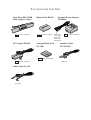
28. Major Accessories:
(1) Battery Pack BP-511
(2) Compact Power Adapter CA-PS400
(3) DC Coupler DR-400
(4) Interface Cable IFC-200PCU
(5) Video Cable VC-100
(6) Battery Grip BG-ED3
(7) Dedicated strap
* Also see page 39 for system accessories.
1-25
Part 1: General Information
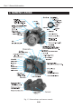
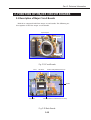
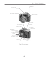
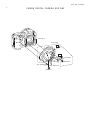
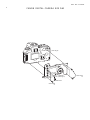
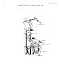
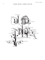
4. NOMENCLATURE
Fig. 1-3 Nomenclature and camera controls.
1-26
Part 1: General Information
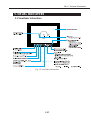
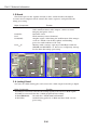
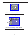
5. VISUAL INDICATORS
5.1 Viewfinder Information
Fig. 1-4 Viewfinder Information
1-27
Part 1: General Information
5.2 LCD Panel Information
Fig. 1-5 LCD Panel Information
1-28
Part 1: General Information
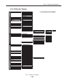
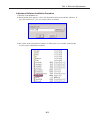
5.3 LCD Monitor Display
Fig. 1-6 Menu Commands
1-29
Part 1: General Information
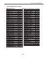
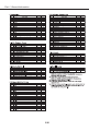
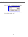
6. CUSTOM FUNCTION
Fig. 1-7 Custom Functions
1-30
Part 1: General Information
7. DIMENSIONS & PROGRAM DIAGRAMS
7.1 Dimensions
Fig. 1-8 Six Exterior Views
1-31
Part 1: General Information
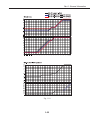
7.2 Program Diagrams
Fig. 1-9 AE Programs
1-32
Part 1: General Information
Fig. 1-10
1-33
Part 1: General Information
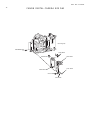
8. SYSTEM ACCESSORIES COMBATIBILLITY TABLES
8.1 System Accessories
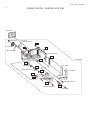
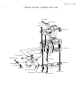
Fig. 1-11 System Accessories
1-34
Part 1: General Information
8.2 EOS System Accessories
1-35
Part 1: General Information
1-36
Part 1: General Information
9. COMPARISON WITH OTHER MODELS
9.1 Comparison with Competing Models
Table 7 Comparison with Competing Models
1-37
Part 1: General Information
9.2 Comparison with EOS Cameras
Table 1 Comparison of EOS D60, EOS D30, and EOS-1D Specifications
1-38
Part 1: General Information
1-39
Part 1: General Information
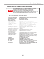
10. OPERATION CAUTIONS
10.1 Operaton Cautions
1-40
Part 1: General Information
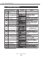
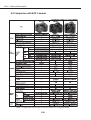
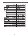
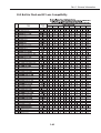
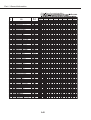
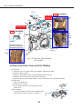
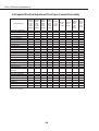
10.2 Built-in Flash and EF Lens Compatibility
1-41
Part 1: General Information
1-42
Part 2
Technical
Information
Part 2: Technical Information
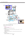
1.TECHNICAL DESCRIPTION
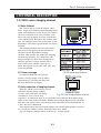
1.1 CMOS sensor imaging element
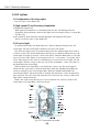
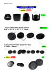
1) Major features
The camera has a Canon-developed, ultralarge, single-piece CMOS (complementary metal
oxide semiconductor) sensor to give the camera
the best resolution in its class. Primary-color
filters are used to obtain accurate and vibrant
color reproduction. Except for the smaller pixel
size, the CMOS sensor's size is the same as the
EOS D30's. The major specifications are shown
in Table.
The imaging element now has more pixels.
The area of each pixel is about half that of
the pixels on the EOS D30's imaging
element. This smaller size makes the imaging
element less sensitive. To compensate, the
design and process have been revamped so
that the aperture is larger and the micro
lenses have more efficient convergence.
Thus, ISO speeds of 100, 200, 400, 800, and
1000 are possible.
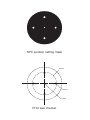
Fig. 2-1 CMOS sensor (actual size)
CMOS Sensor Specifications
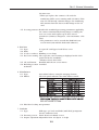
2) Picture coverage
As with the EOS D30, the effective
picture coverage (angle of view) will be
equivalent to a lens with 1.6 times the
EF lens' marked focal length.
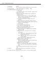
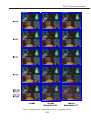
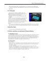
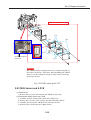
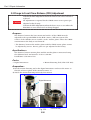
3) Noise reduction of imaging element
With the CMOS sensor's dark current
reduction and the image-reading
circuit's noise reduction, the image
Fig. 2-2 Picture coverage comparison (actual size).
recording is clear even for long
exposures. As shown by Fig.2-4, it even looks better than the EOS D30's image
taken in the noise reduction mode. Thanks to this major improvement, the EOS
D60 does not require noise reduction for long exposures as the EOS D30 did, so
C.Fn-1 has been eliminated.
This improvement also has helped enhance the normal photographic sequence.
As a result, the shutter-release time lag is also more stable.
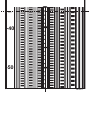
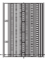
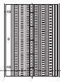
Fig.2-4 compares images taken at the 30-sec. shutter speed.
2-1
Part 2: Technical Information
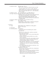
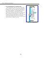
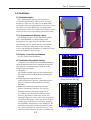
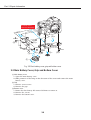
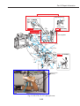
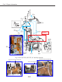
4) Countermeasures for red ghosting
With the EOS D30, when there was a strong light
source within the picture, red ghosting would appear
symmetrically or near the light source depending on
the shooting conditions. In the EOS D60's Low Pass
Filter (LPF) assembly, by switching to a hybrid
construction consisting of the optical low-pass/IR cut
filter, the dichroic mirror with a new coating that
changes the spectral transmittance in front of the LPF
and the IR absorption glass with new absorption
characteristic behind the LPF, the red ghosting problem
has been almost completely resolved.
Fig. 2-3 LPF construction.
2-2
Part 2: Technical Information
Fig. 2-4 Comparison of images taken at 30 sec. (cropped portions)
2-3
Part 2: Technical Information
1.2 Image recording and processing
1) Imaging engine
The EOS D60's imaging engine (system LSI) is an improved version of the EOS
D30's imaging engine that was designed to incorporate primary-color filters. The
major features are as follows:
• Newly-developed signal-processing algorithm
• Faster signal processing
• Faster JPEG compression and decompression
• Thumbnail image-generating circuit produces better image quality
2) Image quality
Images can be recorded in one of six JPEG settings (lossy compression) and
RAW (lossless compression)/12 bit). The EOS D60 has two more image quality
settings (Middle/Fine and Middle/Normal) than the EOS D30 for a total of seven
image quality settings. You can select the image quality setting according to the
pixel count or compression rate.
Also, the EOS D60's RAW images have a JPEG-Middle/Fine image in the
thumbnail-recording area within the .crw file. By using the dedicated driver
(provided), you can now extract the JPEG file from the RAW image.
With the EOS D30, the image quality was fixed at Large/Fine in the Easy
Shooting Zone modes. However, with the EOS D60, you can set any image quality.
Image Quality
3) ISO speed setting
The ISO speed can be set to 100, 200, 400, 800, or 1000. All the ISO speeds are
equivalent to the respective film speeds.
Although ISO 1600 is provided by the EOS D30, the EOS D60 does not. Since
the EOS D60's imaging element has more pixels, the smaller pixel size results in
lower sensitivity and S/N ratio. Since the EOS D30's image quality at ISO 1600
would be difficult to obtain with the EOS D60, ISO 1600 was not included.
2-4
Part 2: Technical Information
4) Processing parameters (image-processing settings)
Besides the three processing parameters
(contrast, sharpness, color saturation) provided by
the EOS D30, the EOS D60 also has color balance
for a total of four processing parameters. Besides
the "Standard (all set to 0)" setting, up to three
sets of parameter settings can be set with the
camera.
"Color balance" is mainly used to adjust flesh
Fig. 2-5 Processing parameters.
tones for portraits. Adjustment toward the minus
side makes it redder, and the plus side makes it yellower.
To set the processing parameters with the EOS D30, the camera must be
connected to a personal computer and a driver is necessary. However, with the
EOS D60, the processing parameters can be set with the menu functions
displayed on the rear LCD monitor.
5) White balance
With a TTL system that uses the imaging
element, optimum white balance can
always be attained under various shooting
conditions. The selectable settings are the
same as the EOS D30's white balance
settings.
The only difference is that the color
temperature for the "Daylight" setting has
been changed from 5500 K to 5200 K for
better image quality.
6) File numbering system for recorded images
It is the same as with the EOS D30.
2-5
White Balance Settings
Part 2: Technical Information
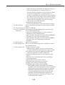
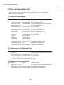
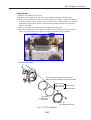
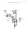
1.3 AF system
1) Configuration of focusing optics
It is the same as the EOS D30.
2) High-speed AF and focusing computation
(1) Brightness range for AF
With improved maximum accumulation time for the AF and improved AF
algorithm, AF performance limit in low light has been improved by 1.5 stops (EV
2 to EV 0.5).
(2) AF speed, AF point automatic selection algorithm, and predictive AF control
These are all the same as the EOS D30.
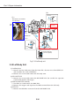
3) AF-assist light
As with the EOS D30, the EOS D60 has a built-in krypton lamp for the AFassist light. The AF-assist light is linked to the three AF points.
The AF-assist light turns on automatically when the ambient light level is EV 4
or lower or when the AF has difficulty achieving focus. With the EOS D30, the AFassist light can light up to three consecutive times. With the EOS D60, it can light
up to six consecutive times (current point of focus → near point → far point: twice
each). This improves the chances of obtaining accurate focus in low light. The AFassist light's effective range is about 3.8 m at the viewfinder's center, the same as
the EOS D30's AF-assist light.
When an EX-series Speedlite is used with the camera, the AF-assist light is
emitted in the same way as with the EOS D30. With the 550EX and 420EX, AFassist is emitted by the external Speedlite. With the 220EX and 380EX, the
external Speedlite's AF-assist beam is emitted only when the center AF point has
been selected. If an off-center AF point has been selected, the camera's AF-assist
light will be emitted instead.
With C.Fn-5 (AF-assist/flash), you can now disable the camera's built-in AFassist light or the Speedlite's AF-assist beam.
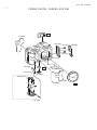
Fig. 2-6 Cross section at center.
2-6
Part 2: Technical Information
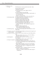
1.4 Viewfinder
1) Viewfinder optics
The configuration and specifications (0.88×
viewfinder magnification, 95% picture coverage,
20mm eye relief) are the same as the EOS D30's
viewfinder. Note that although the focusing screen is
the same New Laser Matte type, the dispersion
characteristics have been improved to make it easier
to discern the focus point during manual focusing.
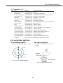
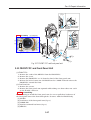
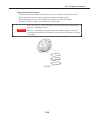
2) SI (Superimpose) display optics
The SI display optics for the AF points include
three small SI-LEDs (1.9 dia) in front of the
pentaprism. The light from the SI-LEDs passes
through SI prisms 1 and 2 and the main mirror
before reaching the AF points on the focusing
screen. The SI display brightness is about the same
as the EOS ELAN 7/7E, 30/33's.
Fig. 2-7 SI display optics.
3) Dioptric correction mechanism
It is the same as the EOS D30.
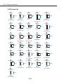
4) Viewfinder information display
Compared to the EOS D30's information display,
the EOS D60 provides more information with the
following four new information displays at the
bottom of the viewfinder:
(1) SI display
The display and AF point selection method are
the same as with the EOS ELAN II/ELAN II E,
50/50E.
(2) Flash exposure compensation icon
Lights when flash exposure compensation has
been set with the built-in flash or external
Speedlite.
(3) Maximum burst during continuous shooting
During continuous shooting, the current
maximum burst is displayed from 0 to 8
according to the amount of available buffer
memory. Regardless of the drive mode, the
maximum burst decreases with each shot taken.
(As with the EOS D30, while the shutter button
is fully depressed during continuous shooting,
the viewfinder information is not displayed. The
maximum burst thus cannot be known.) When
the captured images are saved on the CF card
and more buffer memory becomes available, the
2-7
Fig. 2-8 Maximum burst display
during continuous shooting.
Fig. 2-9 Remaining shots
display.
Part 2: Technical Information
maximum burst increases. Normally, "8" is displayed for the maximum burst.
(4) Shots remaining
When the CF card has room for less than 8 shots taken in the current image
quality mode, the shots remaining will be displayed automatically in place of the
maximum burst. The shots remaining decreases from [8] to [0] with each shot
taken. When the CF card becomes full, "FULL CF" is displayed.
1.5 Exposure control mechanism
1) Metering
The metering optics, 35-zone AE sensor, and metering modes (evaluative, partial,
center weighted average) are the same as the EOS D30's. The metering algorithm
is based on the EOS D30's, but since there were a few user complaints about the
exposure shifting when the picture was slightly recomposed, the metering
algorithm's α compensation increment has been made finer, from 1/2 to 1/4, to
obtain more stable exposure control.
2) Exposure control
It is the same as with the EOS D30.
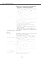
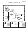
1.6 Drive
1) Continuous shooting speed
It is the same as with the EOS D30.
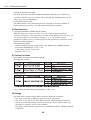
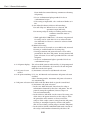
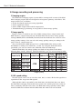
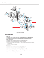
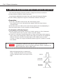
2) Maximum burst during continuous shooting
With the EOS D30, the maximum burst for Large/Fine is about 8 as shown in
Table 11. In the other image quality settings, the
maximum burst varies. However, with the EOS
D60, the maximum burst is always 8 regardless of
the image quality and ISO speed.
* Despite the EOS D60's higher number of pixels
(more data per shot), the maximum continuous
shooting speed of 3 fps is maintained and the
maximum burst during continuous shooting is
also maintained at the same level as the EOS
D30's. To achieve this, the buffer memory was
increased and the image processing that the
EOS D30 executed during continuous shooting
Maximum Burst
was eliminated (as shown by Fig. 2-10's red
arrows, the image is processed in accordance
with the stipulated image quality and
parameters from the 1st to 2nd buffers). As a
result, the maximum burst is always 8, limited
only by the 1st buffer memory's capacity.
* During RAW shooting with the EOS D30, the
maximum burst during continuous shooting
Fig. 2-10 Image-processing flow.
was 3 shots due to the 2nd buffer's capacity
2-8
Part 2: Technical Information
limit. With the EOS D60, a maximum burst of 8 is possible in the RAW mode.
Continuous shooting in the RAW mode is therefore now more practical with the
EOS D60.
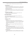
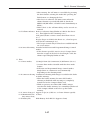
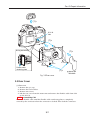
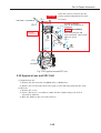
1.7 LCD panel
Except for the addition of Middle/Fine and
Middle/Normal, the information displayed is the
same as the EOS D30's LCD panel.
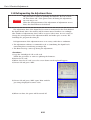
EOS D60 now has LCD panel illumination (EL
backlight).
When "LCD panel illumination" is enabled with
the on-screen menu, pressing the SET button
turns the LCD panel illumination on or off. The
illumination time is about 4 sec, but it will stay on
Fig. 2-11 LCD panel illumination
if you operate any buttons or dials to take a
picture.
* If C.Fn-12-1/2/3 (SET button function during shooting) has been set, pressing
SET will not turn off the LCD panel illumination (it will turn off automatically).
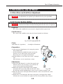
1.8 Built-in flash
It is the same as the EOS D30's built-in flash.
1.9 Basic operation concept and LCD panel display
1) Operation concept
The EOS D60's operation concept is based on the EOS D30. Regardless of what
mode the camera is currently in, the camera will immediately be able to take a
picture when you press the shutter button or any of the shooting-related buttons
(metering mode/flash exposure compensation button, drive mode button, AF
mode/WB button, AE/FE lock button, AF point selector).
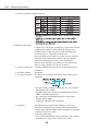
2) LCD monitor
(1) LCD monitor
The 1.8-in. TFT color monitor on the back of the camera is the same size as the
EOS D30's. You can check the images you shot and view on-screen menus to
set various options.
The TFT color monitor has a sheet of material which increases the screen
brightness. The brightness at a viewing angle from 0ºC to about +/-40ºC is the
same as the EOS D30's TFT monitor. The brightness at viewing angles greater
than 40ºC is now much higher as shown in Fig. 2-13.
2-9
Part 2: Technical Information
Enhanced
brightness sheet
Fig. 2-12 TFT monitor construction.
Fig. 2-13 TFT monitor brightness comparison.
(2) Menu configuration
The menu's basic configuration is the same as the EOS D30's with three menu
groups: Shooting, playback, and setup. They are looping menus. Three new
menu options have been added: "LCD panel illumination," "C.Fn cancel," and
"Firmware ver." The menu options are displayed in Table.
Regarding CF card initialization, the name has been changed from "CF card
initialize" to "Card initialize." This is to prevent confusion with C.Fn.
Menu Options
3) Playback/Erase protection
It is the same as the EOS D30.
4) Information display
The method for displaying the shooting/playback information is the same as the
EOS D30. The information displayed is the same as the EOS D30 except for the
following two changes:
Camera Info.: The processing parameter information has been changed to "/0/+" to match the displayed setting.
Single-frame display Info.: The "F" indicating the aperture has been eliminated.
2-10
Part 2: Technical Information
Fig. 2-14 Camera Info.
Fig. 2-15 Single-frame display Info.
5) Jump feature
It is the same as the EOS D30's.
1.10 Improved firmware
1) Shorter shutter-release time lag and better stability
The firmware has been revamped for the EOS D60. As a result, the shutterrelease time lag is now shorter and more stable.
Regardless of the shutter speed, the shutter-release time lag (stop-down by up
to 4.5 stops from maximum aperture and excluding AF operation time) will be as
follows:
With SW-1 ON, the time between SW-2 ON and the start of exposure:
Approx. 100 ms.
The time from simultaneous SW-1 and SW-2 ON to the start of exposure:
Approx. 240 ms.
Also, the viewfinder blackout time is about 300 ms. This is about the same as
film-based EOS cameras.
2) Shorter startup time from power off
With the EOS D30, each time the camera started up from power off (main switch
off or auto power off), it accessed the recording media and read the occupied-area
information. For the EOS D60, the firmware has been modified so that the
recording media's occupied-area information remains in the camera's memory
when the power is turned off. Therefore, there is no need to read the occupiedarea information during startup. This makes the startup time shorter.
Since the CF card is a semiconductor integrated circuit, there is little startup
time difference compared with the EOS D30. However, with a MicroDrive storage
device, there is a big difference in the startup time.
When the power is turned off, the camera still detects
whether the CF card slot cover has been opened or
closed. If the slot cover has been opened or closed, the
occupied-area information will be read during startup as
Comparison of Startup Time
with the EOS D30.
2-11
Part 2: Technical Information
1.11 Internal construction
1) Internal construction
It is based on the EOS D30. The chassis is made of stainless steel and
engineering plastic. The external cover's inner side has a high-frequency, ion
plating finish for better protection against electromagnetic fields, static charge, etc.
Fig. 2-15 shows a cross-section diagram. Fig. 2-16 shows the location of the
major mechanical components, and Fig. 2-17 shows the location of the major
circuit boards.
2) Parts count
The EOS D60's parts count is shown below.
• The shutter unit is counted as 1 part.
• The DC/DC converter is counted as 1
part.
• When there are multiple units of the
same part, they are all individually
counted.
• The official total excludes the screws
and washers.
Parts Count
3) Shutter-release mechanism
It is the same as the EOS D30's.
1.12 Custom Functions
The Custom Functions different from those of the EOS D30 are listed in the
tables below.
The EOS D30's C.Fn-1 (noise reduction for long exposures) is not provided in the
EOS D60 because, as mentioned in 1.1 3), the improved CMOS sensor has
eliminated the need for noise reduction. The image quality is now better than the
EOS D30's even without noise reduction. C.Fn-1 is left unused, and the camera
does not display the C.Fn-1 number.
New Custom Functions
2-12
Part 2: Technical Information
Modified Settings
1.13 Compatibility with accessories
Compatible with all EOS D30 accessories.
Fig. 2-16 Cross section at center.
Fig. 2-17 Location of major mechanical components.
2-13
Part 2: Technical Information
Fig. 2-18 Location of major circuit boards.
2-14
Part 2: Technical Information
2. FUNCTION OF MAJOR CIRCUIT BOARDS
2.1 Description of Major Circuit Boards
EOS 60 is composed with four major circuit boards. The following are
descriptions of the four major circuit boards.
Super impose
SP Light PCB
C-MAIN PCB
Fig. 2-19 Front Boards
EF-IC
AE Sensor
DC/DC PCB (located below OLC)
D PCB
TFT-LCD
TFT PCB
A-PCB (located on C-MOS below TFT LCD)
Fig. 2-20 Back Boards
2-15
Part 2: Technical Information
1. D Board
This board process the signals of main section, and it includes the digital
section's microcomputer which controls the entire sequence and performs the
image processing.
Major Components
IC3(CPU)
Function
Reads all operation and status switches, and controls
USB communication, video output, camera section's
imaging and power source.
Real-time clock
Flash memory (stores firmware)
Graphic engine. After fixing the malfunction of the images
such as C-MOS scratch data update and shading,
processes and readouts to CF card.
Memory with a storage capacity of 128 Mbytes with the
SDRAM and 256 Mbits × 4. Serves as a temporary storage
for the data after image processing
IC4(RTC)
IC11
IC12(DSP)
IC14
17
IC14
IC16
IC15
IC17
IC3
IC12
IC4
IC11
Fig. 2-21 D1 Board
Fig. 2-22 D2 Board
2. A (analog) Board
Generates the CMOS-driving pulse and converts the C-MOS output from analog to digital.
Major Components
Function
IC5004(A/D converter) Converts the analog signal to the 12 bit C-MOS signal.
IC5006(D/A converter) Sets the C-MOS peripheral bias voltage.
IC5008(EEPROM)
Records the C-MOS initial information
IC5010(TG)
Sends driving pulse for C-MOS and does dark current
processing.
2-16
Part 2: Technical Information
IC5006
IC5010
IC5008
IC5004
Fig. 2-23 A Board
3. TFT Board
The TFT board interfaces the display system with other systems.
Major Components
IC7(LCD driver)
IC15, IC6 (Video amp)
Interface part
Function
Controls TFT-LCD display.
Video signal amp
Cable release part and USB communication part.
Cable release
IC7
IC15
USB port
Fig. 2-24 TFT Borad
4. C-MAIN Board
Controls light metering,focusing, flash, and communicate with EF lens.
Major Components
MPU
Function
Camera microcomputer
2-17
Part 2: Technical Information
3. SWITCHES AND THEIR FUNCTIONS
The following switches are found on the EOS D60.
(1) Operation Switches
No. Code
1 SW1
2 SW2
3 MAIN SW
4 AEL SW
Name
Focusing/metering
Release
Main
AE lock
5 FPSEL SW
Focusing point
selector
6 DRIVE MODE SW Drive mode
selector
7 AF/WB SW AF/WB selector
8 MES SW
Metering mode
selector
9 POP UP SW POP UP
10 SPDN SW Depth-of-field
preview
11 MENU
Menu button
12 INF0.
Info. button
13 JUMP
14 MG SW
18 PLAY SW
Jump Button
Enlarge button
Play button
19 ERASE
Erase button
20 SET
Setting button
Function
Starts autofocusing and metering.
Starts the exposure.
When ON, turns on camera.
When ON, AE lock applied. (AE lock also
applied while metering is active.)
When ON, enables manual focusing point
selection with the electronic dial. (Sub
electrical dial can also be used.)
ON+ electronic dial operation enables
drive mode selection.
ON+ electronic dial operation enables AF mode
selection. ON+ sub electronic dial operation
enables
WB mode selection.
ON+ electronic dial operation enables metering
mode selection. ON+ back cover Quick Control
dial operation enables flash exposure
compensation.
When ON, the flash pops up.
When ON, metering starts and the diaphragm
stops down at the set aperture value.
When ON, the back cover Quick Control dial
selects the tag.
When ON, enables checking the settings. When
PLAY, displays the image infomation.
When ON, jumps to next/former 10th frame.
ON+ the Quick Control dial enlarges the image.
When ON, the image is displayed, Serial play
with the sub electric dial operation.
Erases captured images. When ON, erase
selection menu is displayed.
When ON, enables setting functions.
2-18
Part 2: Technical Information
Mode dial button
Built-in flash button
Main Dial button
POP UP SW button
SPDN SW button
Drive mode SW button
MES SW button
AF /WB SW button
AEL SW button
FPSEL SW button
MAIN SW button
MENU button
INFO button
MG button
Jump button
PLAY SW button
Setting button
Erase button
Quick Control Dial button
Fig. 2-25 Switch Names
2-19
Part 2: Technical Information
(2) Status & Mechanical Switches
No. Code
1 MIF SW
2 BATSEL SW
3 BAT SW
4 SWBIRI SW
5 CHG1,2 SW
6 SWX SW
7 CN2 SW
8 CFCVR SW
Name
Lens SW
Function
Detects whether a lens is attached or
not.
Battery detection SW Detection switch for Lithium-ion battery
Battery cover detection Open when a battery is installed, and
SW
battery cover open / close status is
detected.
Shock prevention SW Prevents electrical shock.
Shutter-cocking
Detects shutter cocking, etc.
phase SW
X SW
Flash synchronization detection
2nd-curtain SW
Detects the end of the 2nd shutter
curtain's movement.
CF card cover
Detects the opening/closing of the CF
detection SW
card cover.
BATSEL SW
BAT SW
CFCVR SW
Fig. 2-26 CF Cover
Fig. 2-27 Battery cover
Fig. 2-28 Battery Chamber
CHG . SW
CN2 SW
SWX SW
Fig. 2-29 CHG . SW
Fig. 2-30 Shutter lead wires
2-20
Part 2: Technical Information
4. CIRCUIT OUTLINES
4.1 Power Supply Control
The power is supplied from
the battery terminal and is
input to the DC/DC PCB. The
input power takes two signal
paths. One power supply path
is directly connected to the
MD PCB where the input
power is called VBAT. It is not
fused. The other power path
is connected to the DC/DC
converter circuit through the
fuse.
CPU
V30
DC/DC PCB
E41,10,11
E0,2,3,40
FUSE
BATTERY
TERMINAL
DC/DC
CONVERTER
V0 (3.35V)
(E0) CNTL 0
V1 (3.35V)
(E2) CNTL 1
V2 (5.2V)
(E2) CNTL 1
V4 (4.25V)
(E40) CNTL 2
V33 (15.0V)
(E40) CNTL 2
V32 (6.0V)
(E3) CNTL 3
V31 (6.0V)
VBAT
REG.
3.2V
4.8V
MD FPC
CPU
MPU
SW
FLASH,MOTOR
Fig. 2-31
4.1.1 Output Power from the DC/DC Converter
1) E0 (CNTL0) (Regulated)
The E0 (CNTL0) control signal is always turned ON while the main power is
turned ON. This signal is temporarily ON when the lens is attached, the CF door
is opened/closed and the CF is attached even if the main power is turned OFF.
• V0 (3.35 V): Power for the D PCB, TFT PCB circuit and A PCB TG
• V1 (3.35 V): Power for the CF card
2) E2 (CNTL1) (Regulated)
The E2 (CNTL1) control signal is turned ON while the camera is operating.
This signal is temporarily ON when the lens is attached and the flash unit is
popped up.
• V4 (4.25 V): Power for the camera (mechanism system)
• V2 (5.2 V): Power for the camera (microprocessor system)
3) E40 (CNTL2) (Regulated)
The E40 (CNTL2) control signal is ON when the TFT LCD is ON.
• V32 (6 V), V33 (15 V): Power supply for TFT PCB.
4) E3 (CNTL3) (Regulated)
The E3 (CNTL3) control signal is ON when driving the C MOS sensor.
• V31 (6.0 V): Power for the A PCB.
5) E10, E11: E41 (Regulated)
These E10, E11 control signals turn ON/OFF the output power of the DC/DC
converter as described below.
• E41: This control signal turns ON/OFF the power supplied to the video output
amplifier. The signal is turned ON when insertion of the video jack is detected by the
video jack insertion detection.
4.1.2 VBAT Power
The following power supplies are generated from the VBAT power that is
supplied from the battery terminal.
1) Power to the CPU
2) Power to the MPU
3) Power to the flash and motor circuits
2-21
D PCB
REG.
Part 2: Technical Information
4.2 Main System
The CPU (V30) on the D PCB is the main system control IC. It performs the
controls such as receiving the operation switch data, power supply control, USB
communication and OLC display and performs the following IC controls also.
• TG : Creation of the C MOS drive pulse • RTC: Clock count for clock
• LCD DRIVER: Driving the TFT LCD • FLASH: Firmware memory
• MPU (H12): Camera system control • DSP: Image processing
A PCB
TFT PCB
C-MAIN PCB
LCD
DRIVER
TG
MPU
H12
POWER
CONT.
SW,KEY
CF
CARD
CPU
V30
DSP
OLC
DIGITAL
TERMINAL
(USB)
FLASH
RTC
D PCB
Fig. 2-32
4.3 Camera System
The MPU (HC12) on the C-MAIN PCB performs the following controls.
• AE/EF/AF sensor
• Shutter, AF auxiliary lamp
• Motor (for shutter, mirror and pop-up the flash)
• ILC (finder LCD) display
• EF lens
• Flash charging circuit
EF
LENS
AF
AUXILIARY
LAMP
SHUTTER
UNIT
FLASH
CHARGE
CIRCUIT
MOTOR
DRIVER
M
PHASE
SW
AE
SENSOR
C-MAIN
PCB
MPU
H12
EF
SENSOR
AE
SENSOR
SP LIGHT PCB
ILC
Fig. 2-33
2-22
ACC
SHOE
Part 2: Technical Information
4.4 Video Signal
1) A PCB
The C-MOS sensor drive pulses are generated by the TG circuit that is operated
by the clock signal from the DSP and by the sync signal.
The video signal is output from the C MOS sensor when it is driven by the drive
pulse. The output video signal from C MOS is converted to the digital data by the
A/D converter, passes through the TG circuit and is sent to DSP of the D PCB.
2) D PCB
The DSP circuit performs the following signal processing.
• Processes the video data. (Using the SDRAM)
• Writes and reads the video data to and from the CF card.
• Outputs the video data to the CPU.
• Outputs analog video signal to the LCD and VIDEO OUT.
3) TFT PCB
The video signal that is supplied form the DSP is controlled by the LCD driver
and is displayed on the LCD. The video amplifier is activated when a jack is
inserted into the video jack and drives the 75 ohm video signal.
4) Selecting the ISO sensitivity
The C-MOS sensor gain is switched by changing the amplifier gain (supporting
ISO100 to 400) on the A PCB and the DSP amplifier gain (supporting ISO800 to
1600).
A PCB
D PCB
TG
DRIVE PULSE
SDRAM
TFT PCB
C MOS
HD,VD
CLK
SENSOR
AMP
DSP
A/D
CF
CARD
LCD
DRIVER
VIDEO
AMP
CPU
Fig. 2-34
2-23
TFT
LCD
VIDEO
OUT
USB
Part 2: Technical Information
5. ERROR CODE DISPLAY
As with other cameras, you can check the camera's condition in the inhibit
mode. In the camera's inhibit mode, Err XXX is displayed. The user can see five
types of error codes. Using the service adjustment software, you can check the
detailed error codes and also erase error codes.
<User-viewable Errors>
Display XX
Description
01
Lens faulty
02
CF card faulty
04
Folder limit / CF card has
inadequate storage space.
05
99
Flash pop up error
Other defects
Probable Cause and Countermeasures
• Lens communication error at shutter
release.
• Lens diaphragm does not stop down
at shutter release.
• Lens detection SW does not change.
• CF card connector pin faulty.
• CF card faulty.
• The number of folders created
exceeded the limit.
Delete unnecessary folders.
• Pop-up switch error
• Faulty system, DC/DC fuse blown.
<Detailed Error Codes> (Viewable with the adjustment software.)
Error code
The part that is suspected
Contents
1
2
as the cause of the error
10000000 00000000 Lens aperture blades does not operate Lens
01000000 00000000 Lens aperture blades is not Lens
set in the full open state
00100000 00000000 Lens communication error
Lens
00010000 00000000 Mirror up cannot be implemented Mirror box unit
00001000 00000000 Mirror down cannot be implemented Mirror box unit
00000100 00000000 Shutter charge cannot be implemented Mirror box unit
after mirror is raised up
00000010 00000000 Rear screen switch is not turned Shutter unit
off after release
00000001 00000000 Completion of charging is not output Shutter unit
after the pre-illumination
00000000 01000000 X-contact does not turn on
Shutter unit
00000000 00010000 X-contact is turned on at mirror up Shutter unit
00000000 00001000 Flash cannot be popped up
Top cover unit
00000000 00000100 * CGE is open during standby Mirror box unit
00000000 00000010 * Mirror up is short-circuited at standby Mirror box unit
00000000 00000001 * CN2 is open at standby
Shutter unit
OLC
99
* When any digit other than the specified digit goes "1", the specific trouble may be
caused by the other error.
In such a case, clear the error once and check the operation again in order to
specify the error.
2-24
Part 3
Repair
Information
Part 3: Repair Information
1. PREPARATION FOR REPAIR
Be sure to read the following before starting the repair work
1.1 Flash High Voltage Circuit Precaution
• As soon as the front cover is removed, be sure to bleed the main capacitor.
(Bleeder resistor: 500 ohms, approx. 10 W.)
• The bleeding contacts are the XE (+) side and GND onthe STR PCB.
Contact the bleeder resistor with GND first, then with the XE (+) side.
CAUTION
HIGH VOLTAGE! Be careful of electric shock !
TOP FPC, lower
TOP FPC
Fig. 3-1 Flash Capacitor Bleeding Points
1.2 Power Consumption
Regulated Power Supply
Power Consumption Standard
Lens : EF 50mm f/1.8
Power Supply : Regulated
Power
Supply:7.5V, 0.4Ω
Ambient conditions: Room temperature, normal
humidity (below 60%)
Digital Multimeter
(Amp range)
Tool Battery
-
+
+
-
To camera under test
Fig. 3-2 Power Consumption Measurement Method
Camera Setting
Product Standard
Actual Measured Value*
Stand-by
SW-1 On
Less than 150µA
Less than 300mA
Approx.45µA
Approx.280mA
* : Values measured from early production cameras. Values may vary somewhat
with later lots.
3-1
Part 3: Repair Information
1.3 Tools and Expendables List
The following tools, test equipment and expendables are necessary during
repair. Have them on hand.
1) Tools and Test Equipment
New Name
EF-8000 Multi-camera Tester
EF-5000
Color Viewer (5600K)
Color Bar Chart
Regulated DC Power Supply
Mount Fastening Tool
Digital Micrometer
AF Standard Tool Lens
Video Light
Flash meter
Penlight
Tripod
Dark Bag
Multimeter
AF Standard Chart
C12 Filter (2 each)
Luminance Meter BM-300
Luminance Meter BM-3000
Part No.
CY9-7073-000
CY9-7086-000
DY9-2039-100
DY9-2002-000
CY9-1547-000
Local Purchase
CY9-1072-001
Local Purchase
Local Purchase
Local Purchase
Local Purchase
Local Purchase
Local Purchase
CY9-1124-000
CY9-1546-000
NPN
CY9-7052-000
Areas where used
Light Source ("A" Light Source)
Light Source ("A" Light Source)
Electrical Adjustments
Electrical Adjustments (Color Adjustment)
Electrical Adjustments
FFD adjustment
FFD Adjustment
AF Accuracy Adjustment
AF Focus Adjustment, etc.
Flash Exposure Adjustment
SPC Positioning
AF Adjustment
White Balance Adjustment
Light Source Calibration
Light Source Calibration
2) Charts and Locally Fabricated Tools
New Name
Part No.
Areas where used
18% Gray Standard Panel
Flash Exposure Adjustment
3D chart
See EF 300mm f/4.0L IS Service Manual
SPC Positioning Mask Local Fabrication As necessary
X-sync Time-lag Tool Local Fabrication X-sync time lag
Tool Battery
Local Fabrication Inhibit Voltage adjustment
* : Refer to Locally Fabricated Tools for details.
3) Products necessary for Testing
New Name
Part No.
EF 50mm f/1.8 Lens
EF Speedlite (A-TTL type) 300EZ, 540EZ
EF Speedlite (E-TTL type) 380EX, 550EX
3-2
Areas where used
Various Operational Checks and Adjustments
Flash Exposure Adjustment
Flash Exposure Adjustment
Part 3: Repair Information
4) Expendables List
New Name
Light-shield Tape
Scotch tape
Double-sided tape
Aron-Alpha 201
Arontite L
Three bond 1401C
UTLM-10
Silicon KE347B
Grease H-26
IF10
Barrierta SJF-102 Grease
Oil Retardent
Logenest Lambda A-74
Dia-bond 1663G
Logenest Lambda NK-74C
Cemidine Super XNo8008
NoxGuard ST-420
Logenest Lambda NFH-743C
PL015JG
Part No.
CY9-4026-000
CY9-4031-000
CY9-4034-000
CY9-8007-000
CY9-8008-000
CY9-8011-000
CY9-8031-000
CY9-8064-000
CY9-8079-000
CY9-8088-000
CY9-8100-000
CY9-8101-001
CY1-8102-000
CY9-8129-000
CY1-8117-000
CY9-8118-000
CY9-8123-000
CY1-8125-000
CY9-8073-000
Areas where used
Motor
Pentaprism assembly
Fixing lens mount contact ass'y leads
Fixing the SPD and SI
Staking screw heads
Staking screws
Mirror Mechanism
Protecting high voltage and other cables
Dial Unit, etc.
Mount spring
Release contacts
Prevent oil smear around mount
M2 gear shafts
Attaching parts together
Shafts, other friction surfaces
Fixing Mount Ring, etc.
Parts assembly
Front Panel friction surfaces
Sliding part of back cover dial
1.4 Locally Fabricated Tools
1) SPD Positioning Mask
2) X-sync Time-lag Tool
Open holes in flat black paper as shown
Assemble a 4.7kΩ resistor from CCC
to GND.
ø 57mm
ø 4~6mm
ø 2~3mm
Fig. 3-3 SPD Positioning Mask
Fig. 3-4 X-sync Time-lag Tool
3-3
Part 3: Repair Information
1.5 Body Serial Number Position
This is a serial number for after-service information.
Products for sale start from No. 0110100001.
X X X X X X X X X X
Serial No. (00001~99999)
Classification No. (01~99)
Type of model (1. NTSC (DOM), 2. NTSC (USA, CAN),
3. PAL)
Date of production (2002, JAN.=00~2003, oct.=21)
1.6 Flexible Connectors
The product uses three kinds of the locking connector.
[1] Type A
[2] Type B
The connector
should face
UNLOCK
downwards
The connector
should face
UNLOCK downwards
Unlocked
Unlocked
[3] Type C
UNLOCK
The connector
should face
upwards
Unlocked
Fig. 3-5 Flexible connectors
CAUTION
1. Before inserting or removing the flexible cable,
be sure to unlock the connector. After
insertion, be sure to lock it.
2. The Type B has a two-stage connection
structure. Insert it to the deep end to avoid
short-circuiting the terminals. Insert it so that
the clearance between the cut-out of the
flexible cable reinforcement plate and the
connector is about 0.3 mm.
3. The flexible cable has holes for insertion and
removal. Use them for removal and insertion
by inserting the tweezers into the holes as
required. (Fig. 3-7)
3-4
Holes
Fig. 3-6 Holes for removal
Flex holes
Part 3: Repair Information
2. DISASSEMBLY/ASSEMBLY
(1)-1
(1)-2
f
5.5mm
g
CAUTION
Be Carefull!! High-voltage Circuit
may cause an electric shock.
TOP FPC, lower
Black
Orange
Dowel
(2)-3
NOTE : Assembling
The switch
(SW) on the
flexible board
must be
inside the
dowel.
(2)-1
l
v
3.5mm
Attach with DB1663B
Route the leads so
that they do not
overlap in the
shaded area
during assembly.
5.5mm
Dowel
m
4.5mm
(2)-2
NOTE : Assembling
Fig. 3-7 Terminal cover and front cover
CAUTION
Discharging the main capacitor.
When the front cover is removed, be sure to discharge the main
capacitor before proceeding to the next step.
2.1 Terminal Cover and Front Cover
(1) Terminal cover
1. Remove two screws.
2. Open and pull the extension terminal cover, then
remove it together with the terminal cover.
(2) Front cover
1. Remove the grip rubber.
2. Remove five screws.
3. Remove the front cover.
3-5
NOTE : Assembling
When attaching the front cover,
confirm that the cables and other
wires are not pinched.
Part 3: Repair Information
Be careful not to
loose the cable door.
(2)-2
(3)-3
u
3.0mm
v
3.5mm
(2)-1
(2)-1
5.0mm
ad
(1)-2
4.0mm
ab
4.0mm
(2)-1 ab
(3)-2
h
2.5mm
(3)-1
(3)-2
A
(1)-1
Fig. 3-8 Main battery cover, grip and bottom cover
2.2 Main Battery Cover, Grip and Bottom Cover
(1) Main battery cover
1. Open the main battery cover.
2. Slide portion A of the hinge in the direction of the arrow and remove the main
battery cover.
(2) Grip
1. Remove seven screws.
2. Remove the grip.
(3) Bottom cover
1. Rotate the date battery lid counterclockwise to remove it.
2. Remove five screws.
3. Remove the bottom cover.
3-6
Part 3: Repair Information
(1)-1
D P.C.B.
CN4
(1)-4
During assembling
(1)-2
k
4.5mm
h
2.5mm
Flexible cable
reinforcing plate
h
2.5mm
(1)-3
Attach with
DB1663B
Fig. 3-9 Rear cover
2.3 Rear Cover
(1) Rear cover
1. Remove the eye-cup.
2. Remove the back rubber.
3. Remove six screws.
4. Lift the rear cover from the main unit and remove the flexible cable from CN4
on the D PCB.
NOTE : Assembling CN4
Insert the flexible cable until the flexible cable reinforcing plate is completely
covered by the connector when the connector is locked. Then lock the connector.
3-7
Part 3: Repair Information
(1)-1
(1)-2
(1)-2
5.0mm
i
NOTE : Assembling
Be careful
not to loose
the buttons.
Cushion
Fix by
tape
6.5mm
j
Be careful not to
loose the buttons.
(1)-5
NOTE : Assembling
Hole
Fix by tape
(1)-3 (1)-4
White
Yellow
(1)-4
White
Yellow
Dowel
Orange Orange
The SW on the FPC
should be attached to
the dowels and holes.
(1)-4
(1)-4
Blue
Blue
B
FRONT FPC
CN TOP
Yellow
Black
A
Black
Yellow
Fig. 3-10 Top cover, flash cover and
OLC window
2.4 Top Cover, Flash Cover and OLC Window
(1) Top cover
1. Remove the screw and remove the diopter adjustment knob.
2. Remove three screws.
3. Remove the flexible cable from the FRONT FPC CN TOP.
4. Remove the six lead wires on portions A and B.
5. Remove the top cover while being careful not to loose the operation buttons.
(2) Flash cover
1. Raise the flash unit.
(2)-3
2. Remove two screws.
3. Press down the flash unit and remove the
flash cover.
(2)-1
(3) OLC window
(3)-1
(2)-3
Push the flash side of the OLC window from
Claw
Double-sided
the bottom of the top cover to remove it.
tape
e
4.0mm
(2)-2
3-8
Part 3: Repair Information
(4)-1
Be careful not to loose the bracket
w
5.5mm
n
2.5mm
Be careful
(3)-1
Apply Screw lock
(3)-1
(4)-1
Be careful
(1)-1
w
5.5mm
Normally not
necessary
to remove
ae
4.5mm
(1)-2
Be careful
Be careful
z
4.5mm
(2)-1
2.5mm
p
Apply Three Bond 1401C
to the screw head.
(1)-1
Fig. 3-11 Rear frame, eyepiece cover and strap holder
2.5 Rear Frame, Eyepiece Cover and Strap Holder
(1) Rear frame
1. Remove ten screws.
2. Remove the rear frame.
(2) Eyepiece cover
1. Remove the screw and eyepiece cover.
(3) Strap holder (right)
1. Remove the screw and remove the strap holder (right).
(4) Strap holder (left)
1. Remove two screws and remove the strap holder (left).
3-9
r
2.5mm
(2)-1
Part 3: Repair Information
(1)-1
Remove the
lead wire
Remove the
soldering
(1)-1
4.5mm
ac
(1)-2
Remove two
screws
(3)-2
(2)-3
4.0mm
ab
A
CN3
(2)-3
CN1
(3)-1
CN4
CN7
ab
4.0mm
aa
3.5mm
CN2
Replacing TFT LCD.
ab
4.0mm
3.5mm
aa
(2)-1
(2)-2
Fig. 3-12 OLC, TFT PCB and TFT LCD
2.6 OLC, TFT PCB and TFT LCD
(1) OLC unit
1. Remove two lead wires for EL.
2. Remove two screws.
3. Remove the OLC unit from CN3 on D PCB.
(2) TFT PCB
1. Remove the flexible cable and cables from the connectors CN2, 1, 3, 4 and 7
on the TFT PCB.
2. Remove three screws.
3. While removing the two dowels "A", pull up the TFT PCB from the above to
remove it.
(3) TFT LCD unit
1. Remove four screws.
2. Remove the TFT LCD, lifting it from its top.
3-10
Part 3: Repair Information
Normally not necessary to disassemble
Align with this line.
Attach together
after overlapping
them.
Shaft
Shaft position
(3)-1
NOTE 3 : Assembling
NOTE 2 : Assembling
Be careful not to
loose the bracket. y
4.0mm
(3)-3
(3)-2
n
2.5mm
Screw lock is applied.
(4)-1
4.0mm
CN5001
y
(2)-1
(4)-2
(2)-1
(1)-4
CN2 (1)-2
(1)-1
2.0 CN1
mm
q
t
3.5mm
(1)-3
ab NOTE 1 : Assembling
4.0mm
(1)-1
(1)-1
CN8
(1)-2
4.0mm
CN7
B
3.0mm
u
ab
(1)-3
DA32
FPC
Remove these
soldering
Put the flexible cable
in-between the shield
Fig. 3-13 D PCB, CF FPC and right cover
3-11
Chassis
Part 3: Repair Information
2.7 D PCB, CF FPC and Right Cover
(1) D PCB
1. Remove the soldering from the flexible connector and shield plate.
2. Remove the flexible board from the connectors CN5001 on the A PCB and the
connectors CN2, 7 and 8 on the D PCB.
3. Remove four screws.
4. Remove the connector CN1 (B to B) and remove the D PCB.
NOTE 1 : Assembling
1. The connector "B" of DA32 FPC must be inserted between the screw and the D
PCB.
(2) CF FPC unit
1. Remove four screws and remove the CF FPC unit.
(3) Right cover
1. Unsolder three points on the flexible connector.
2. Remove two screws.
3. Remove the right cover.
NOTE 2,3 : Assembling
3. Align the position of the shaft of the CF cover with the line and attach the CF
cover from the lower flexible connector retainer. Then, fasten the screw.
4. Overlap the two upper flexible connectors, then attach them.
3-12
Part 3: Repair Information
Normally not necessary to disassemble
s
3.0mm
(1)-1
s
3.0mm
(1)-3
(1)-3
(1)-4
(1)-3
(1)-2
(1)-1
(1)-5
(1)-2
4.5mm
ac (1)-1
Sensor focus washers
attach here
4.5mm
ac
(1)-2
(1)-2
(1)-4
CAUTION
The CMOS sensor is fragile and can be easily damaged by
the static electricity. Therefore, when handling the CMOS
sensor, use the antistatic strap, or other static electricity
protective devices
Fig. 3-14 CMOS sensor and A PCB
2.8 CMOS Sensor and A PCB
(1) CMOS sensor
1. Remove three screws and remove the CMOS sensor unit.
(2) Disassemble CMOS sensor and A PCB
1. Unsolder at three points and remove the shield case.
2. Remove three screws, then remove the LPF and LPF rubbers.
3. Unsolder the foot of the CMOS sensor from the A PCB.
4. Separate the A PCB from the CMOS sensor.
3-13
Part 3: Repair Information
(1)-2
(1)-3
B
ae
4.5mm
ab
4.0mm
(1)-7
(2)-1 c
SH
FPC
(1)-5
(1)-3
(1)-3
Normally not
necessary
to disassemble
CN MD
(1)-5
(1)-1
(2)-2
ae
4.5mm
PHASE
FPC
(1)-4
(1)-2
(3)-1
Fix with double-sided tape
Fig. 3-15 DC/DC PCB, MD FPC, AF auxiliary indicator
Remove the black and pink lead
wires
Remove the blue and orange lead
wires
Remove the comb
Remove the soldering
B
C
Remove the lead wire of the AF
auxiliary indicator
3-14
Part 3: Repair Information
2.9 DC/DC PCB, MD FPC, AF Auxiliary Indicator part
(1)Remove MD FPC
1. Unsolder the seven lead wires near the lens mount on the MD FPC and the
SH FPC and PHASE FPC connectors.
2. Peel off the MD FPC beside the lens mount from the chassis (fixed with
double-sided tape) and open the unit so that the top of the MD FPC becomes
visible.
3. Remove the four lead wires(the motor and the lead wire of AF auxiliary
indicator part), from MD FPC and also remove the comb of the portion "A".
4. Unsolder the two lead wires from the ILC FPC.
5. Remove the flexible boards from the CN MD of the C-MAIN PCB, remove the
screw.
6. Remove the MD FPC.
(2) Remove DC/DC PCB
1. Remove the soldering from the portion "C".
2. Unsolder the two lead wires from the battery terminal.
3.Remove two screws from DC/DC PCB and remove DC/DC PCB.
(3) AF auxiliary indicator part
1. Remove the screw and AF auxiliary indicator part.
3-15
Part 3: Repair Information
(4)-1
STR FPC
(1)-1
Remove the 6 lead wires
and STR FPC
SP LIGHT
PCB
STR
FPC
Normally not
necessary
to disassemble
Z
4.5
mm
aa
3.5mm
(4)-1
(2)-1
(1)-2
(1)-2
FRONT FPC
3.5
aa mm
(3)-1
(2)-1
A
RMC
FPC
(3)-2
(3)-1
Double-sided tape
(for main capacitor)
Fig. 3-16 Left body unit
2.10 Left Body Unit
(1) Left Body Unit
1. Remove the four lead wires from the front FPC, the two wires from STR PCB
and unsolder the comb of STR FPC.
2. Remove two screws and remove the left body unit.
(2) SP LIGHT PCB
1. Remove two screws and remove the SP LIGHT PCB. (Be careful, the capacitor
is fixed with double-sided tape.)
(3) RMC terminal/FPC, left body
1. Unsolder at A and remove the RMC FPC.
2. Remove the stopper and separate the RMC terminal from the left body.
(4) STR FPC
1. Remove the STR FPC connector from the SP LIGHT PCB.
3-16
Part 3: Repair Information
(1)-1
The PC terminal leads
must be routed under
the FPC.
(1)-4
NOTE : Assembling
[1]
[1] [2] [3] [4] [5]
[5]
(2)-2
[2]
[4]
CN FRONT
1
2
5
[3]
(1)-4
4
ac
4.5mm
3
4.5mm
ae
(2)-1
A (1)-3
q
2.0mm
(1)-2
Fig. 3-17 FRONT FPC and front panel unit
2.11 FRONT FPC and Front Panel Unit
(1) FRONT FPC
1. Remove the comb of the MIF FPC from the FRONT FPC.
2. Remove the screw.
3. Remove the FRONT FPC at "A" from the dowel of the front panel unit.
4. Release the lock of connector CN FRONT on the C-MAIN PCB and remove the
FRONT FPC toward the front.
(2) Front Panel Unit
1. Remove five screws.
2. Remove the front panel unit upwards while taking care that it does not catch
on the flexible connector.
NOTE : Assembling
Before starting to install the front panel unit, be sure to pull these lead wires of
the front panel unit to the front through the clearance with the FRONT body.
[1] SH FPC
[2] Lead wires of the front panel unit (5 pcs.)
[3] PHASE FPC
[4] Synchro terminal lead wires (2 pcs.)
[5] MIF FPC
3-17
Part 3: Repair Information
r (3)-1
2.5mm
(3)-6
(3)-2
ac
4.5mm
(2)-1
(3)-5
Black
4.5mm
ac
(1)-2
90˚
A
(1)-1
4.5mm
a
(3)-4
o
2.0mm
ae
4.5mm
(3)-3
(3)-2 (2)-1
B
(2)-4
(1)-1
aa
3.5mm
Don't lose !
(2)-3
Be careful spring loaded.
a
4.5mm
(1)-1
(2)-2
4.5mm
ac
(2)-1
Fig. 3-18 Front body
2.12 Front Body
(1) Main dial
1. Remove three screws, and remove the main dial and the RELEASE FPC.
2. Unsolder at "A" and separate the main dial from the RELEASE FPC.
(2) Main battery case
1. Remove three screws and remove the main battery case.
2. Remove the screw and remove the battery terminal.
3. Push thru the hole of the portion "B" with tweezers and remove the battery
spring holder.
4. Remove the battery spring.
(3) Front body
1. Remove three screws and remove date battery case.
2. Remove four screws and remove the tripod socket.
3. Remove two screws and remove the battery door hinge.
4. Remove the black lead wires of the synchro terminal.
5. Rotate the stopper 90 degrees to remove the stopper. Then remove the
synchro terminal.
6. Remove the front body insulation sheet.
3-18
Part 3: Repair Information
CAUTION
(1)-2
Flat head ( ) screwdriver
If the SPC unit is removed, the AE
sensor position adjustment becomes
necessary.
5.0mm ad
(2)-2
(2)-3
Normally not
necessary
to disassemble
Connect by adhesive
(such as Aron-Alpha 201 or
equivalent)
NOTE : Assembling
After adjusting the AE
sensor position, attach with
adhesive agent.
(2)-1
(1)-2
aa
3.5mm
(1)-1
CN SENS
Fig. 3-19 Eyepiece lens and SPC unit
2.13 Eyepiece Lens and SPC Unit
(1) Eyepiece lens unit
1. Remove the FPC from the CN SENS of the C-MAIN PCB.
2. Remove two screws and remove the eyepiece lens unit along with the SPC Unit.
(2) SPC unit
1. Remove the screw.
2. Insert a flat head (-) screwdriver under the SPC holder and peel it off. It is
attached by adhesive.
3. Move the holder to the rear and remove it.
3-19
Part 3: Repair Information
CAUTION
V
Regulated power supply
(0.7 V approx.)
A
GN
D
(2)-1
(2)-2
CN ILC
(1)-1
Blue
(2)-2
Orange
Light shield attachment position
Shutter position
4.0mm
ab
ac
4.5mm
(1)-2
A
(1)-1
CN BA
aa 3.5mm
NOTE : Assembling
NOTE : Assembling
(1)-2
lead wires
layout
Black
Yellow
The mirror-down state
Charged state
Align the lever with the groove when installing the shutter unit.
Fig. 3-20 Shutter unit and C-MAIN PCB
2.14 Shutter Unit and C-MAIN PCB.
(1) Shutter unit
1. Apply about 0.7 volts to the shutter motor and stop the shutter at the position "A".
2. Remove three screws and remove the shutter unit.
NOTE : Assembling
(1) Attach the light-shield, the flexible cable, and the lead wire to the shutter unit.
(2) Set the shutter unit in the charged state, and the mirror in the mirror-down position.
CAUTION
Install the shutter unit.
(2) C-MAIN PCB
1. Remove the flexible connector from the connectors CN ILD and CN BA.
2. Remove two screws and remove C-MAIN PCB.
3-20
Part 3: Repair Information
NOTE 2 : Assembling
NOTE 1 : Assembling
ILC holder
Insert the
black sheet of
the AF unit
into this
clearance.
Backlight LED
(2)-1
4.0mm b
(1)-1
ab
4.0mm
(1)-1
Fig. 3-21 ILC and AF unit
2.15 ILC and AF Unit
(1) ILC unit
1. Remove the screw and remove the ILC unit.
NOTE 1 : Assembling
Confirm that the backlight LED is correctly inserted in the ILC holder.
(2) AF unit
CAUTION
When AF unit is removed, the AF sensor position adjustment becomes necessary.
After adjusting the AF sensor position, fix the head of the fixing screw with the
adhesive.
1. Remove two screws and remove the AF unit.
NOTE 2 : Assembling
Insert the black sheet of the AF unit into the position shown in the illustration.
3-21
Part 3: Repair Information
Adjustment required. (Finder’s focus adjustment)
NOTE 1 : Assembling
Be careful
Loose parts.
Inside the mirror box
(4)-1
ab
4.0mm
Coat IF10
(On the rear of the spring)
Adjustment required.
(FFD adjustment)
A
Matte surface
(1)-2
Claws
NOTE 2 : Assembling
d
6.5
mm
Fresnel
lens
A (1)-1
(2)-1
d
6.5mm
4.0mm ab
Apply
adhesive.
Black
Pink
Double-sided tape
(3)-2
(3)-1
(2)-1
Apply screw lock
Fig. 3-22 Focusing screen, lens mount and lens mount contact assembly
2.16 Focusing Screen, Lens Mount and Lens Mount Contact
Assembly
(1) Focusing Screen
1. Place the tweezers' in the hole at "A", and push to the rear until the claws are
unlocked, then press down to remove.
2. Remove the focusing screen and focusing adjustment washer.
NOTE 1 : Assembling
Insert the focusing screen and focusing washer into the respective specified
positioning holes.
(2) Lens mount
1. Remove four screws and remove the lens mount.
(3) Lens mount contact assembly
1. Remove two screws.
2. Remove the two lead wires from the front panel unit and remove the lens
mount contact assembly.
NOTE 2 : Assembling
Fix the lead wire to the position shown in the figure 3-23.
(4) Mirror box cover
1. Remove two screws and remove the mirror box cover.
3-22
Part 3: Repair Information
(3)-1
With double-sided tape
NOTE : Assembling
Be careful Loose
parts.
Coat the face of back cover dial with PL-015
(2)-2
Ball
(1)-3
Spring
(2)-3
Fix it using
D1663B
(1)-4
(1)-1
LED window
Be careful Loose
parts.
(1)-3
(1)-4
Insert the tweezers
from inside and
remove it upwards.
(1)-2
Be careful
Loose
parts.
(1)-5
c 2.5
mm
(1)-6
x
3.5mm
Screw
hole
(1)-8
(1)-7
Screw hole Dowel holes
(2)-1
Fix it using
D1663B
ab
4.0mm
(1)-1
4.0mm ab
Be careful Loose
parts.
Fig. 3-23 Rear cover block
2.17 Rear Cover Block
(1) BUZZER FPC
1. Remove six screws.
2. Remove the FPC holder plate.
3. Remove the washer, connector, and switch from the back cover (quick-control) dial switch block.
4. Remove the access lamp block from the rear cover with the FPC attached to
the LED window.
5. Unsolder the FPC from the buzzer.
6. Remove the BUZZER FPC from the rear cover.
7. Peel off the main dial FPC from the BUZZER FPC.
8. Peel off the adhesive and remove the LED window.
(2) Back cover dial
1. Remove two screws. Remove the washer and connector from the back cover dial block.
2. Remove the back cover dial while taking care not to drop the click spring and ball.
3. Remove the E-ring and remove the SET button.
NOTE : Assembling
When assembling the back cover dial, insert the spring and ball into the dial first.
After assembling, check the click stops as you rotate the dial.
(3) TFT LCD window
1. Remove the TFT LCD window by pushing on it from inside the rear cover.
3-23
Part 3: Repair Information
2.18 Screw List
a
b
c
d
e
CB1-0279
CB1-1902
CB1-2678
CB1-4085
XA4-6170-409
4.5mm
METAL
M1.7
(SELF TAPPING)
4.0mm
6.5mm
2.5mm
BLACK
M1.7
(SELF TAPPING)
METAL
M1.7
4.0mm
BLACK
M1.7
(SELF TAPPING)
METAL
M2.0
(SELF TAPPING)
f
g
h
i
j
CB2-0719
CB2-0720
CB2-0721
CB2-0722
CB2-0723
2.5mm
6.0mm
5.5mm
5.0mm
FLAT BLACK
M1.7
(SELF TAPPING)
FLAT BLACK
M1.7
FLAT BLACK
M1.7
FLAT BLACK
M1.7
6.5mm
FLAT BLACK
M2.0
(SELF TAPPING)
k
l
m
n
o
CB2-0724
CB2-0726
CB2-0727
FC2-9551
XA1-3170-207
4.5mm
FLAT BLACK
M1.7
5.5mm
FLAT BLACK
M1.7
(SELF TAPPING)
2.5mm
4.5mm
METAL
M2.0
with adhesive
FLAT BLACK
M1.7
(SELF TAPPING)
2.0mm
METAL
M1.7
p
q
r
s
t
XA1-3200-257
XA1-7170-207
XA1-7170-259
XA1-7170-309
XA1-7170-357
2.5mm
METAL
M2.0
2.0mm
2.5mm
METAL
M1.7
3.0mm
BLACK
M1.7
METAL
M1.7
3.5mm
METAL
M1.7
u
v
w
x
y
XA1-7200-307
XA1-7200-359
XA4-9200-559
XA4-5140-357
XA4-5170-407
3.0mm
METAL
M2.0
3.5mm
BLACK
M2.0
z
aa
XA4-8200-459
XA4-9170-357
4.5mm
BLACK
M2.0
(SELF TAPPING)
3.5mm
ae
XA4-9200-457
4.5mm
METAL
M2.0
(SELF TAPPING)
3-24
4.0mm
METAL
M1.7
(SELF TAPPING)
ac
ad
XA4-9170-457
XA4-9170-509
4.0mm
BLACK
M1.7
(SELF TAPPING)
3.5mm
METAL
M1.4
(SELF TAPPING)
ab
XA4-9170-409
METAL
M1.7
(SELF TAPPING)
BLACK
M2.0
5.5mm
4.5mm
METAL
M1.7
(SELF TAPPING)
5.0mm
BLACK
M1.7
(SELF TAPPING)
Part 3: Repair Information
3. MECHANICAL ADJUSTMENT
3.1 Main Mirror and Sub Mirror Adjustment
CAUTION
No adjustment is required. (pre-adjusted service parts provided)
3.2 AF Sensor Position Setting
CAUTION
Perform the AF Sensor Position Setting when the AF sensor is replaced.
<Purpose>
The center of the middle AF sensor must be aligned with the optical axis.
<Specifications>
The center of the middle sensor must be located inside the AF frame.
Fig. 3-24 AF frame and BASIS
<Tools>
• EF 50mm f/1.8 (product)
• Penlight or illuminator
<Preparation>
1) Close the lens diaphragm to f/8 using the product
body of EOS-D60.
* Set the EOS-D60 to MANUAL mode and set the
aperture to f/8. Then remove the lens while
depressing the rear depth-of-field button.
2) Set the distance scale of the lens to the × (infinity)
end.
(The AF frame can be viewed more easily.)
<Adjustment>
1) Attach the EF 50mm f/1.8 to the front panel unit
with the mirror unit, focusing screen and the AF
sensor unit (tentatively fixed) installed.
2) While directing the output light of the penlight
Fig. 3-25
toward the AF sensor unit, look into the lens. Then
the AF frame and the BASIS image can be seen as shown in Figure 3-26.
3) Move the AF sensor unit right and left until the center is located in the center
of the AF frame.
4) Tighten the screw fixing the AF sensor unit gently, and apply Three Bond
1401B to the screw head (If over-tightened, the sensor position may change.)
3-25
Part 3: Repair Information
3.3 Flange to Focal Plane Distance (FFD) Adjustment
CAUTION
Perform the FFD Adjustment when the mirror box unit or mount is
replaced.
No adjustment is required for the CMOS sensor service parts (preadjusted at the factory).
Perform the FFD Adjustment when tilt focus error occurs when the
EOS-D60 receives shock such as being dropped.
<Purpose>
The distance between the lens mount and surface of the CMOS must be
adjusted to the specified FFD for the EOS camera / EF lens system. The
surface of the CMOS is not accessible, so the "washer plane" where the CMOS
unit mounts to the body is used instead.
* The distance between the washer plane and the CMOS sensor plane cannot
be adjusted by service. Service parts are pre-adjusted at the factory.
<Specifications>
The distance between mount plane and the washer plane is measured using
the dedicated tool, and must be 41.30 ± 0.02 mm.
Parallelism: 0.04 mm or less
<Tools>
• Digital micrometer
• Mount Fastening Tool (CY9-1547-000)
<Preparation>
1) Set the mount fastening tool to the digital micrometer and reset the meter so
that the reference plane of the mount becomes "0".
2) Attach the mount fastening tool to the lens mount.
set to "0"
0.000
Digital Micrometer
Fig. 3-26
3-26
CY9-1547-000
Part 3: Repair Information
<Adjustment>
1) Remove the CMOS censor unit.
2) Measure the distances to the respective CMOS mounting washer planes.
3) If the measured distance does not satisfy the specifications, adjust the distance
by replacing the mount with the service mount (CY1-1280) and by selecting the
appropriate adjustment washer (CB2-0682-000-XXX) until the specification
value is satisfied.
* Refer to the Part List for details of the adjustment washers.
4) After the adjustment, take a picture of the 3-D chart and check the best focal
point. If an adjustment is required, perform AF shift at same position.
CB2-0682 x3 (See Detail)
Service mount (The service mount is thinner
than the normal mount that is used in the product)
XD1-1102-120
XD1-1102-121
XD1-1102-122
(Service Only)
Adjustment washer
CB1-2659
(Service Only)
(See Detail)
CA1-7777
CY1-1280 (Service Only)
Fig. 3-27 FFD adjustment
3-27
Part 3: Repair Information
3.4 Finder Focus Adjustment
CAUTION
Perform the Finder Focus Adjustment only after the FFD Adjustment
is completed.
<Purpose>
The sensor focus point and the finder focus point must be the same.
<Specifications>
The center of the × (infinity) mark must be positioned within the 1.5 index line
widths of the index line as shown below.
8
2.5
22
15
5
ft
m
11
11
22
Fig. 3-28 Focusing scale window of lens
<Tools>
• Magnifier AD-S
• Lens with focusing scale. Lens of 100 mm focal length or less is desirable.
• General purpose 500mm collimator
<Adjustment>
1) Without the lens attached to the EOS-D60, adjust so the AF frame in the
center of the finder is using the diopter adjustment dial of the camera.
2) Attach the magnifier to the camera eyepiece and adjust the diopter of the
magnifier. (Adjust the diopter without the lens attached.)
- Dioptor adjustment method With the camera pointed at a wall having the high brightness and high
reflectance (such as white wall having EV12 or the light source of the shutter
testing equipment), adjust the diopter adjustment ring of the magnifier until
the AF frame is sharpest.
3) Attach the lens, and set the distance scale to × (infinity). (If the center of the ×
(infinity) mark is positioned within the 1.5 lines widths of the index line, it is
satisfactory.)
4) Shoot an object that is located at least 250m away (such as lightening rod or
chimney) and select the finder focus washer that gives the clearest view of the
object.
* When a collimator is used, select the focus washer that gives the clearest view
of the collimator scale.
3-28
Part 3: Repair Information
- Replacement of focus washer Push in the two round holes of the focusing screen retainer with tweezers, then
the focus washer can be removed together with the focusing screen.
When doing so, take care not to push too strongly. If you do, the spring
pressure of the focusing screen retainer becomes weak.
CAUTION
Take care not to scar the focusing screen and print-type mask during
the above adjustment work.
When re-assembling the parts back to the original product, check to
see that the focusing screen and the focusing screen retainer are surely
set in place.
Fig. 3-29
3-29
Part 3: Repair Information
4. SIMPLIFIED MEASUREMENT METHOD OF EXPOSURE AND SHUTTER
The histogram display function provides a simple but effective method of
checking exposure and the shutter operation.
Removing the DIGITAL block takes time and using the histogram display
function enables judgment of exposure and shutter without removing it.
<Preparation>
1) Press the <AF/WB> button in the left of the display panel.
Turn ON the back cover dial and let the display show the white balance
selection mode.
2) Turn the back cover dial to select the desired option name by highlighting it.
3) Set the white balance to the incandescent lamp marking.
<Confirmation of Shutter Speed>
1) Set the shutter speed of the camera to 1/4000, aperture to f/2.8, luminance
LV15 and K value to 12.5. Let the camera close the shutter.
2) Check to see that the normal histogram as shown in the figure below appears.
If the center of the histogram is either in the right or in the left, the histogram
indicates that the amount of incident light on the CMOS sensor is either
excessive or short. It is suspected that the shutter speed of 1/4000 is actually
not realized.
CAUTION
If luminance of EV15 is not correct, center of a picture is not
positioned in the center as shown in the figure below. Luminance at
EV15 and K value 12.5 is 4096 cd/m2.
When the histogram has a symmetrical
shape, it indicates that the correct shutter
speed is obtained. Refer to the figure in the
right.
Normal
The shutter
closes early
The shutter
closes late
3-30
Part 3: Repair Information
<Confirmation of Exposure>
1) Be sure to set the white balance in
tungsten.
2) Set the camera to the program mode
(select either TV or AV mode).
Let the camera close the shutter at each
luminance level.
3) When the exposure is correct, the correct
histogram as shown in the right appears.
The histogram graphs when exposure is
changed, are shown as follows.
0.5 stop under
1 stop under
1.5 stop over
2 stop under
0.5 stop over
1 stop over
1.5 stop over
2 stop over
3-31
Part 4
Electrical
Adjustments
Part 4: Electrical Adjustments
1. ELECTRICAL ADJUSTMENTS
1.1 Cautions
• The adjustment software is compatible with Windows 98 SE, Windows ME, and
Windows 2000. The computer must have a Pentium II 233 MHz or higher
processor, 128 MB of RAM, and a 800×600 (1024×768 recommended) or larger
monitor. To install all the adjustment software, about 20 MB of hard disk space
is required.
• The manuals for the adjustment software are bundled together with the
respective adjustment software program. On the initial screen, you can select
"no camera" so that you can use the software without connecting a camera.
• Before servicing, jot down the user's settings, such as Custom Function (C.Fn)
settings, owner's name, and the serial number. All of the data of the camera
section and the digital section can be saved with the adjustment software by
doing "data save".
• Since the color chart or light source (EF8000, 5000) will have slight
idiosyncrasies, first use a known-good (non-defective) camera to check the
characteristics. For details, see "1.8 Digital Adjustment and Standard Data
Creation."
• Before doing the adjustment, be sure to turn off the "Auto Power Off." If the
power turns off during the adjustment, an error may occur.
• Perform maintenance of the light source (EF-8000, 5000) at regular intervals.
See "1.7 Light Source Maintenance."
• Imager file data is appended in a floppy disk with the replacement parts. If the
imager file data has been lost due to the replacement of the D board, etc., you
can obtain it from the Canon FTP site. To access the Canon FTP site, contact
your local HQ. (FTP site is planned to open up in early 2002.)
• The imager file can be updated (Pixcel dot update added). See "1.10 Updating
the Imager File."
• When exporting the image to an image-editing program such as Photoshop,
make sure the "processing parameters" are set to the standard settings.
• A replacement digital board unit (CG2-0710) from stock may have the old
firmware. Before doing the adjustment, check the firmware version. If it is an old
version, update the firmware before doing the adjustment.
• For the AF adjustment, there is no need to input the flange focal distance. After
the AF adjustment, photograph a 3-D chart and check the focus. If fine
adjustment is necessary, adjust by shifting the AF focus. See "1.9 AF Adjustment."
• If the user says that focusing is faulty, avoid shifting the focus at first. Instead,
try and obtain the user's lens and check it.
• When adjusting the camera's exposure, check the "SPC Positioning Adjustment."
After the digital section adjustments, do a final check.
• New main board units (CG2-0770) already have the initial data written within.
Therefore, initialization is not necessary.
• When adjusting the digital section, defragmentation of the adjusting area may
be required. (Especially when you are transfering the imager file.) See"1.14
Defragmenting the Adjusting Area."
4-1
Part 4: Electrical Adjustments
1.2 Installation Procedure
The TWAIN driver from EOS DIGITAL SOLUTION DISK must be installed.
Supplied software:
• Adjustment software: EOS_D60.exe
• Defragmentation program: EOSD60_Defrag.exe
• CMOS scratch data update program: EOSD60_Compiler.exe
Software to be procured locally:
• Internet Explorer 4 or higher
• EOS D60, TWAIN driver (EOS DIGITAL SOLUTION DISK )
Installation procedure:
Adjustment software installation
1) Install Internet Explorer 4 or higher.
2) Install TWAIN driver (EOS DIGITAL SOLUTION DISK).
* Before installing the adjustment software, make sure it works.
3) Install the adjustment software.
4) Install the CMOS scratch data update program.
5) Re compression the defragmentation program.
Uninstall procedure:
Adjustment software uninstall procedure
1) Move the holder containing the CMOS scratch data update program
(EOSD60_Compiler.exe) to the trash bin.
2) Move the holder containing the adjustment software (EOS_D60.exe) to the
trash bin.
3) Uninstall the TWAIN driver. (See manual.)
4-2
Part 4: Electrical Adjustments
Adjustment Software Installation Procedure
1) Double-click EOSD60.exe.
2) From the list that appears, select the desired location to install the software. If
you click "Reference," you can choose where to install.
3) The name of the adjustment software is "EOS_D60. exe" Double-click this file
to start up the adjustment software.
4-3
Part 4: Electrical Adjustments
CMOS Scratch Data Update Program Installation Procedure
1) Double-click EOSD60Compiler.exe.
2) From the list that appears, select the desired location to install the software.
3) The name of the adjustment software is EOSD60_Compiler. exe" Double-click
this file to start up the adjustment software.
4-4
Part 4: Electrical Adjustments
1.3 Description of Camera's Electrical Adjustments
CAUTION
For AF adjustment, there is no flange focal distance to be input.
After the AF adjustment, photograph a 3-D chart. If fine
adjustment is necessary, adjust by shifting the AF focus.
Before doing the adjustment, be sure to turn off "Auto Power Off." If
the power turns off during the adjustment, an error may occur.
The electrical adjustments consist of the following:
Temperature adjustment
Serial number resetting
Imager file transfer
AE adjustment menu
• Shutter adjustment
• SPC positioning
• AE basic adjustment
• AE shift
Adjustment of the camera's temperature sensor.
Set the serial number.
Transfers the imager file.
Adjust the shutter speed at 1/4000 sec.
Adjustment and check of the AE sensor's position
Adjustment of AE sensor's output.
The exposure level can be shifted in 1/8-stop
increments to suit user preferences.
CMOS Exposure adjustment
Adjustment for the CMOS to obtain the correct
exposure level.
• Black level • ISO Exposure • Shading
White balance adjustment
Adjustment of white balance sensor.
Color matrix adjustment
Adjustment of the color matrix.
AF adjustment menu
• Basic adjustment
Optimum adjustment of the AF sensor's output.
• AF focus adjustment
Adjustment for optimum focus position.
• Image/Focus data
The AF sensor's output data is used for waveform
and chart setting and for AF precision checking,
and displays the focus data.
• AF shift
AF compensation shift
Flash adustment
Adjust EFIC's gain and level
TFT adjustment
Adjust the TFT-LCD's display position.
Self-check
All the camera's LCDs are turned on, error codes
are erased, and the error No.is displayed.
Data transfer
The camera's data can be initialized and the data
can be transferred to be saved.
4-5
Part 4: Electrical Adjustments
1.4 Required Electrical Adjustment Chart Upon Camera Disassembly
Adjustment Items
Shutter speed adjustment
SPC positioning
AE accuracy adjustemt
AE shift adjustment
Basic AF adjustment
AF focus adjustment
Image data/focus data output
Gain adjustment
Level adjustment
LCD full-lighting
Error code deletion
SI luminance adjustment
Error codes
Shutter counter reset
Temperature compensation
Initialization
Data storage
Data transfer
Imager file transfer
Writing camera ID
C-MOS exposure level
adjustment
White balance adjustment
Color matrix adjustment
Writing TFT data
TFT position adjustment
TFT luminance adjustment
Initialization
Data storage
Data transfer
Digital
Board
(CG20773)
(Data
illegible)
Digital
Board
(CG20773)
(Data
legible)
Main
Board
(CG20770)
(Data
illegible)
Main
Board
(CG20770)
(Data
legible)
Shutter
Unit
(CG20761)
AE Unit
(CG13798)
AF Unit
(CG137951)
C-MOS,
Analog
Board
(CY31393
CG10771)
TFT
Board
Unit
(CG10772)
2
3
1
2
*
2
*
4
5
1
2
*
6
7
*
1
None
1
None
1
2
3
1
4
5
6
*
*
3
4
2
1
*
*
* Perform as necessary
4-6
Part 4: Electrical Adjustments
1.5 Checking and Adjusting the AE, E-TTL, and Exposure
CAUTION
The light source (EF8000, 5000) must be maintained as indicated
in "Light Source Maintenance." It must produce the correct
brightness (LV 9 = 64cd/m2) especially if you will check the
exposure level.
The user may request that the exposure level be increased or
decreased. In such a case, first check the exposure level and do the
adjustment with the camera.
Checking the Exposure Level
If the EOS D60's camera metering sensor (SPC) output and the shutter
adjustment are correct, the camera will obtain correct exposure. And if the digital
section's ISO setting is adjusted correctly, the digital section should obtain the
correct exposure. If the user wants the exposure level to be increased or
decreased, check the total exposure level, then refer to it when making the
exposure level adjustment with the camera.
To check the total exposure level, you will need the adjustment software or an
image-editing program like Photoshop. The procedure using the adjustment
software is explained below.
* This procedure is for checking if the exposure level is correct as it would be with
film in a film-based camera.
Total Check
1) Connect the camera and start up the digital adjustment software.
2) Select "Test shooting"
3) Set the camera settings as follows. Take pictures while changing the ISO speed
and shutter speed.
Camera settings
• Camera mode: Aperture-priority AE
• Aperture: f/8.0 (f/5.6 is acceptable)
• Shutter speed: Auto
• ISO: All ISO speeds
• White balance: Tungsten
• Image size: JPEG, L size
4) Press the shutter button.
5) The image will be captured. Drag (select) the mouse at the center of the image.
6) The image's RGB and YCrCb will be displayed. Check that the RGB's G value is
120 count +/-10 count. This 120 ount is the same at all ISO speeds. If you use
an image-editing program like Photoshop, do the same as above by selecting
the image center to display the RGB outputs. If the G value is the same, it is
okay.
4-7
Part 4: Electrical Adjustments
If it does not meet the standard:
Reference
With exposure, each count is equivalent to 0.020EV, so the
exposure becomes 0.20EV at 10 counts. For this reason, you can
judge overexposure and underexposure taking about 120 counts
(dependent on white balance) as the reference when a surface of
uniform brightness is photographed.
Check the CMOS brightness level adjustment and SPC sensor positioning. If it
is not the correct value, correct it. Also, if the user requests an increase or
decrease of the exposure, do the AE shift adjustment with the camera.
Checking the CMOS Sensor Output
1) Connect the camera and start up the adjustment software.
2) Select "Check the Image"
3) Set the camera settings as follows. Take pictures while changing the ISO speed
and shutter speed.
Camera settings
• Camera mode: Manual
• Aperture: f/8.0
• Shutter speed: 1/125 sec. (ISO: 100), 1/250 sec. (ISO: 200), 1/500 sec. (ISO:
400), 1/1000 sec. (ISO: 800)
• ISO: See above "Shutter speed"
• White balance: Tungsten
• Image size: JPEG, L size
4) Press the shutter button.
5) The image will be captured. Drag (select) the mouse at the center of the image.
6) The image's RGB and YCrCb will be displayed. Check that the RGB's G value is
120 count +/-10 count. This 120 count is the same at all ISO speeds. If you
use an image-editing program like Photoshop, do the same as above by
selecting the image center to display the RGB outputs. If the G value is the
same, it is okay.
If it is not 120 count +/-10 count:
• The light source's brightness is in error. --> See "1.6 Light Source
Maintenance."
• The camera's ISO speed adjustment is wrong. --> Adjust the ISO speed. (When
the ISO speed is adjusted, you will also have to do all the CMOS-related digital
adjustments.)
Checking the Camera and AE Sensor Output
CAUTION
Be sure to use a normal EF 50mm f/1.8 lens.
Check the amount of light that the camera's AE sensor receives.
1) Attach an EF 50mm f/1.8 lens to the camera and start up the adjustment
software.
2) Select "AE adjustment" and then "SPC positioning"
4-8
Part 4: Electrical Adjustments
3) Face the camera toward the light source (EF8000, 5000).
4) Change the light source to LV 9, LV 12, and LV 15, and check the SPC output
value. If "12.5" is displayed for the output value when the light source is set to
LV 12, the camera is receiving too much light. Control the exposure by
decreasing it by 0.5 EV.
Required standard: Within +/-0.25 EV at every brightness
If it does not meet the required standard, shift the AE or do the AE basic
adjustment. With AE shift, increase or decrease the overall exposure level. If the
required standard is met at LV 9, but not at LV 15, the exposure's gain must be
adjusted. In such a case, do the AE basic adjustment.
4-9
Part 4: Electrical Adjustments
1.6 Digital Section Adjustment and Standard Data Generation
CAUTION
This procedure must be done before the digital section adjustment.
(Especially, generating this standard data is very important. If it is
not generated, the correct color reproduction will not occur.)
Do the regular maintenance (data generation). (This is not
necessary each time you do the adjustment. However, be sure to do
it when the light source bulb has been replaced or the location has
been changed.
A known-good camera is required for a data generation.
A standard data will be stored in the Reference folder where the
adjustment software has been installed. It is recommended to back
up the data, because it will be deleted when the adjustment
software is deleted or updated.
Before doing the digital section adjustments, the light source and color chart
characteristics must be measured and saved in the personal computer.
Required standard data:
• CMOS white balance data (WhiteBalanceRef.wb)
• Color matrix chart data (MatrixChart.pos)
• Color matrix adjustment data (ColorMatrixRef.mat)
* The name of the file in the Reference folder is in parentheses.
These data are saved within Reference in the folder where the adjustment
software is installed. Be sure to make a back-up copy of these data.
CMOS White Balance Basic Data
The CMOS white balance adjustment is for fixing the irregular output caused by
the CMOS's color. As explained below, use a known-good camera to measure the
light source's characteristics and filter characteristics.
•Required tools
• Light source (EF8000, 5000)
• C12 filter × 2
Adjustment procedure:
1) Attach an EF 50mm f/1.8 lens to the known-good camera and connect the
camera to the computer. Start up the digital section adjustment software.
2) Select "CMOS white balance adjustment."
3) Select "Basic data generation."
4) Set the light source (EF8000, 5000) to LV 12. Set the lens to manual focus and
infinity.
5) After everything is set, click "Set completed."
6) Attach a C12 filter to the lens, and click "Set completed."
7) Attach another C12 filter (total 2 filters) to the lens, and click "Set completed."
The CMOS white balance data's basic data can now be generated. Click "Check
standard data" to check the data. Jot down this data on a piece of paper.
4-10
Part 4: Electrical Adjustments
Color Matrix Basic Data
CAUTION
"Colors" drawn in the graph change according to the overall
exposure level. For this reason, adjust the exposure so that the "Y"
level of the white on the color bar is 178±10 counts during
measurement.
The color matrix basic data is used as the index for judging colors.
Required tools
• Color viewer
• Color bar chart
Measurement procedure
1) Attach a normal EF 50mm f/1.8 lens to the known-good camera and connect
the camera to the computer. Start up the digital section adjustment software.
2) Select "Color matrix adjustment."
3) Select "White balance setting", adjust the white balance to the color viewer. Put
the camera close to the color viewer and press "Release." By releasing, the
white balance
will be memorized.
4) Select "Color setting"
5) Set the camera as follows(It will be set automatically):
• Shooting mode:
Aperture-priority AE
• Aperture:
f/5.6
• ISO:
100
• White Balance:
Auto
• Image size:
JPEG, L-size
5) Place the color bar chart on the color viewer, and adjust so that the chart is
correctly
positioned. For details, see the adjustment screen. After
everything is set, click "Cancel."
6) Select "Image evaluation," and click "Release." When you click "Release," the
image will appear. Select the center of each color.
7) Put the cursor over the graph's point, and right-click the mouse to select "Set."
That point will then be saved. Repeat this step for all seven color bars.
*If the "Y" level is not 178±10 counts, adjust the exposure setting.
If you selected "Set" by mistake, right-click the mouse and select "Clear."
The points you set will become the color bar chart's characteristics. This pointmatching adjustment will be done later.
4-11
Part 4: Electrical Adjustments
1.7 Maintenance of Light Source
CAUTION
Do regular maintenance (data generation). (This is not necessary
each time you do the adjustment. However, be sure to do it when
the light bulb has been replaced or the location has been changed.)
The maintenance procedure is presented in a video called "Repair
Technique Basic 1, 2" (CY8-1310-007, 008 for Japanese and CY81320-007, 008 for English).
For digital cameras, maintaining the light source is very important for adjusting
the ISO sensitivity. With the EOS D60, the standard amount of light for each ISO
speed is set based on the LV12 light source.
* According to the ISO standard, ISO 100's standard exposure amount is
stipulated as 0.1 lux/sec. where the exposure amount (lux/sec.) is expressed in
lux (the light's brightness) and sec. (time of light radiation). Therefore, if you use
ISO 100 film, you can obtain the same result with the same amount of light
regardless of the film's manufacturer.
Required tools
• Light source (EF8000, 5000)
• Luminance meter BM-300, 3000
Procedure
1) Turn on the light source. Wait at least 10 minutes before starting the
measurement. While you wait, thoroughly clean the surface of the light source.
2) Use the luminance meter to measure the light source.
Required standard:
LV 9:
64 cd/m2 (59.7 - 68.6 cd/m2)
LV 12: 512 cd/m2 (477 - 548 cd/m2)
LV 15: 4096 cd/m2 (3821 - 4389 cd/m2)
* The K value is 12.5, correctable within +/-0.1 EV.
3) If adjustment is necessary, adjust with the variable resistor. (see the manual of
EF8000, 5000)
4-12
Part 4: Electrical Adjustments
1.8 Imager File Update
CAUTION
To find the correct location of CMOS defects, a RAW image must be
used instead of JPEG which blurs the defect. The defect location
coordinates to be input are also based on the RAW image.
EOSD60_complier.exe will calculate the location with the full size
pixel of CMOS.That causes the number of pixels' differece from the
full size pixel images(3152 × 2068) to the JPEG (Large-Fine : 3072 ×
2048).
The "defect" found could also be a piece of dust, etc. Before
starting, be sure to clean the CMOS.
The CMOS's defect data can be updated.
* CMOS is susceptible to ultraviolet rays and cosmic rays. Therefore, avoid
leaving a bare CMOS in the open. Store it in a dark place. Also, beware of static
charge. When handling the CMOS with bare hands, be sure to wear grounded
wrist bands.
1. Procedure
<Obtain the imager data of the camera. (Contact Head quarters in your region or access
the FTP site.)>
<Find the defect location specified by the user.>
1) Start up EOSD60Compiler.exe, and open the problem file specified by the user.
Compiler.exe can handle only RAW images. If the image file is JPEG format,
handle the file as a RAW image
(1.1)
(0.0)
referring to "Confirmation
16
Method." The figure on the right
shows the differences between a
72
8
RAW image (2496 × 1662) and
JPEG (Large-Fine: 2646 × 1648)
image. With image processing
software such as Photoshop, the
top left coordinate is expressed
as (0,0), whereas on
Compiler.exe, it is expressed as
(1,1). For this reason, in the case
of positions pointed out by the
user, the defect location at (1234,
321) on a JPEG (Large-Fine) image
is expressed differently as follows:
X=1234+72+1=1307
Y=321+16+1=338
JPEG image
RAW image
4
2) Find the defect. Select the RAW
file by "OPEN" from "FILE" in the
figure on the right.
4-13
Part 4: Electrical Adjustments
3) PClick the button in the figure on
the right. Image enlargement
/reduction and the currently
displayed gain can be changed.
Set the image so that defects can
be distinguished. To do this, set
gain to about 1.0.
4) Click the "Update" button.
5) When you click the "Update"
button, choice of the files will
displayed. Then choose
"xxxxxx_1def." "xxxxxx" is the
CMOS imager file number.
6) Click the defects desired to add.
The coordinates will be added to
the Defect List. If wrong position
is set, choose it and click
"DELETE." Click "SAVE" to add
the coordinates to the file.
7) For the "OUTPUT FILE,"
AjDef00.imag, AjDef01.img,
AjDef02.img, AjDef04.img,
AjDef05.img, AjDef06.img,
AjObSkip.img will be created.
4-14
Part 4: Electrical Adjustments
<Rewrite the data>
1) Connect the camera to the computer, and start up the adjustment software.
2) Select "Transfer imager file."
3) In the text box, type the imager number and click "Update."
4) A dialog box for selecting the imager file will appear. Select the AjDef0?. img,
and AjObSkio. img, files that were created before. The files will then be written
to the camera.
5) After the writing is completed, quit the adjustment software program and turn
on the camera. (If the camera is not turned on, the files will not be updated.)
* When you update the imager file, the CMOS brightness level adjustment need
not be done again.
2. Check Procedure
There are two types of CMOS defects: "White defects" which light up in low light,
and "black defects" which do not light up in bright light. Therefore, depending on
the shooting conditions, there will be defects you can and cannot see. To see the
defects, use the methods described below.
If you cannot obtain a RAW image, also follow the methods below.
<Settings for finding white defects>
1) Attach the body cap to the camera and close the eyepiece shutter. Set the
camera as follows:
Shooting mode:
Shutter-priority AE
Shutter speed:
1 sec.
ISO:
1000
White balance:
Auto
Image size:
RAW
<Settings for finding black defects>
1) Attach an EF 50mm f/1.8 lens to the camera, and set the camera as follows:
Shooting mode:
Aperture-priority AE
Aperture:
f/8
ISO:
100
White balance:
Auto
Image size:
RAW
2) Photograph.
3) Open the captured image with EOSD60 Compiler.exe.
4) Check if the image has been corrected.
4-15
Part 4: Electrical Adjustments
1.9 AF Focus Adjustment Procedure
CAUTION
For the AF adjustment, there is no need to input the flange focal
distance. After the AF adjustment, photograph a 3-D chart and
check the focus. If fine adjustment is necessary, adjust by shifting
the AF focus.
With film-based SLR cameras, the flange focal distance was input during AF
focus adjustment and then the adjustment was made. Since it is difficult to
measure the distance to the CMOS surface, follow the procedure below. Note that
as with mechanical adjustments, the flange focal distance must be adjusted.
(Since it also affects the CMOS's tilt and viewfinder focus.)
<Adjustment Procedure>
1) Attach the tool lens and connect the camera to the HS-I/F or Multiple Tool II.
Then start up the camera adjustment software.
2) Select "AF adjustment" and "AF focus adjustment."
3) Follow the on-screen instructions and do the adjustment with aging and three
charts.
4) Obtain a 3-D chart and place the camera 2.5 meters away from the center of
the 3-D chart.
(Be sure to illuminate the chart with a video light or other light source.)
5) Photograph.
• Shooting conditions
Shooting mode
: Aperturepriority AE
Aperture
: f/1.8
ISO : 100
White balance
: Auto
Image size
: JPEG (Fine)
AF point
: Center only
6) Import the image to an image-editing program such as Photoshop. Check the
image to see how much it is off from the chart. (Good only at the center)
7) If there is no error, the adjustment is completed. If the focus is shifted, correct
the focus with AF focus shift. Calculate the shift amount as shown below. The
AF focus shift can be adjusted in 0.005 mm increments. After completing the
AF shift, repeat from step 5 above to check the adjustment.
CCD off-position amount
Off-position amount relative to subject × 1
(magnification) 2
Off-position amount relative to subject × 1
=
2500 (EF 50mm f/1.8, at 2.5 m)
=
*
• The defocus amount relative to the subject is the 3-D chart's off-position
amount expressed in mm.
• Positive correction (+) will result in a front focus, and negative correction (-) will
result in a rear focus.
4-16
Part 4: Electrical Adjustments
* Reference (Correction amount with an EF 50mm f/1.8, at 2.5 m.)
Distance to Subject
mm
cm
m
Correction Amount
mm
Distance to Subject
mm
cm
m
Correction Amount
mm
12.5
1.3
0.013
0.005
262.5
26.3
0.263
0.105
25.0
2.5
0.025
0.010
275.0
27.5
0.275
0.110
37.5
3.8
0.038
0.015
287.5
28.8
0.288
0.115
50.0
5.0
0.050
0.020
300.0
30.0
0.300
0.120
62.5
6.3
0.063
0.025
312.5
31.3
0.313
0.125
75.0
7.5
0.075
0.030
325.0
32.5
0.325
0.130
87.5
8.8
0.088
0.035
337.5
33.8
0.338
0.135
100.0
10.0
0.100
0.040
350.0
35.0
0.350
0.140
112.5
11.3
0.113
0.045
362.5
36.3
0.363
0.145
125.0
12.5
0.125
0.050
375.0
37.5
0.375
0.150
137.5
13.8
0.138
0.055
387.5
38.8
0.388
0.155
150.0
15.0
0.150
0.060
400.0
40.0
0.400
0.160
162.5
16.3
0.163
0.065
412.5
41.3
0.413
0.165
175.0
17.5
0.175
0.070
425.0
42.5
0.425
0.170
187.5
18.8
0.188
0.075
437.5
43.8
0.438
0.175
200.0
20.0
0.200
0.080
450.0
45.0
0.450
0.180
212.5
21.3
0.213
0.085
462.5
46.3
0.463
0.185
225.0
22.5
0.225
0.090
475.0
47.5
0.475
0.190
237.5
23.8
0.238
0.095
487.5
48.8
0.488
0.195
250.0
25.0
0.250
0.100
500.0
50.0
0.500
0.200
4-17
Part 4: Electrical Adjustments
1.10 Checking the Version
The EOS D60 has version numbers for two software programs.
<Camera section>(Main board unit)
ROM Version(1603)
<Digital back section>(Digital board unit)
Firmware (1.0.0.)
* The version number in parentheses applies to the initial production lot.
The digital back version can be checked with the TFT monitor. However, minor
versions cannot. (They are uploaded without informing the user due to
manufacturing or servicing circumstances.) To check the minor versions, the
digital back adjustment software is necessary. They will appear at the bottom of
the main menu.
4-18
Part 4: Electrical Adjustments
1.11 SPC Positioning Adjustment
The SPC positioning adjustment can be done with or without the adjustment
software. If you do not use the software, you will need a small flashlight and very
refined servicing skills. The procedure without the adjustment software is
explained below.
<Required tools>
Bright penlight
Normal EF 50mm f/1.8 lens
Aron Alpha
<Preparation>
1) Attach the EF 50mm f/1.8 lens to the camera.
2) Cover the viewfinder with your hand matching the AF centering range.
Illuminate the side (the clear portion) of the SPC with the flashlight.
3) Look through the lens, and move the flashlight so that you can see the SPC's
S0 and the border lines. It would be best if you cover the viewfinder so that the
AF point at the center looks dim. Also, if the flashlight is fixed in place, it will
be easier to move the SPC.
<Adjustment Procedure>
1) Move the SPC so that the SPC's S0 is aligned with the AF point at the center of
the viewfinder.
2) Do fine adjustments so that the left and right AF points are centered as well.
Center of the viewfinder
S0
4-19
Part 4: Electrical Adjustments
1.12 Color Matrix Adjustment
Color matrix adjustment is a very important adjustment in determining "color"
on EOS D60.
However, as unevenness in the "color" of the color chart used at adjustment is
reflected on the camera as it is, color matrix basic data and reference data must
be made by "1.5 Description of Digital Section Electrical Adjustments, preparing
basic data."
<Description>
The following is displayed by evaluating the image during image checking and
color matrix adjustment.
Reference data prepared
during servicing
Factory/development reference
color values and standards
When color matrix reference data is prepared, some points may not coincide
with the factory reference color values and standards. This is because a difference
occurs between the factory color bar charts and individual color bar charts. For
this reason, the color may differ from the actual color when adjustments are
performed matched to the factory reference color values and standards.
During color matrix adjustment, the color is matched to the reference data
prepared during servicing. As a guideline for the standard values, the factory
reference color values and standard ranges are shifted centrally to the reference
data prepared during servicing for judgment.
4-20
Part 4: Electrical Adjustments
<Adjustment Method>
If reference data is already made, the adjustment itself is completed by "Setting"
-> "Start adjustment". Note, however, that to respond to user preferences (e.g.
stronger red, blue is too predominant), reference data must be changed, readjusted, and checked.
CAUTION
Before changing the reference data, be sure to record the original
values. Once reference data is changed, the original values are
overwritten.
"Color" drawn in the graph changes according to the overall
exposure level. For this reason, offset exposure during
measurement so that the "Y" level of white on the color bar
becomes 225±10 counts. (This is the same as color matrix basic
data and reference data made by "1.3 Description of Camera's
Electrical Adjustments".)
-
+
-
+
-
+
+
+
-
4-21
Part 4: Electrical Adjustments
1.13 Storing Settings and Adjustment Data
The following tables summarize where the various setup data and adjustment
data are saved, and how to save the data. Refer to these tables when saving data.
* Setup Data
Setup Data
C.Fn (custom function)
Storage Location
Camera (MPU)
Image review time
Red-eye reduction function time
AEB setting
ISO sensitivity
LCD panel illumination
Beep
LCD monitor brightness
Video system
Time
Owner name
Development parameters
Image-recording quality
Auto-power OFF
Language
Date Format
Digital section
Camera
Camera
Camera
Digital section
Camera
Digital section
Digital section
Camera (RTC)
Digital section
Digital section
Digital section
Digital section
Digital section
Digital section
* Camera section
Adjustment Item
SPC positioning
AE adjustment
AE shift
Change exposure program
AF basic adjustment
AF focus adjustment
Image data output
Focus data output
E-TTL gain shift
E-TTL level shift
SI brightness adjustment
Light all LCDs
Erase error code
Temperature adjustment
Shot counter reset
Version/Error code
(RAM)
(RAM)
(RAM)
(flash ROM)
(RAM)
(RAM)
(RAM)
(RAM)
(flash ROM)
(flash ROM)
Storage Location
None
MPU
MPU
MPU
MPU
None
None
MPU
MPU
MPU
None
MPU
MPU
MPU
MPU
4-22
Save Method
Camera section
or TWAIN driver
Not possible
Camera section
Camera section
Camera section
Not possible
Camera section
Not possible
Digital section
Not possible
Not possible
Not possible
Not possible
Not possible
Digital section
Digital section
Save Method
Camera section
Camera section
Camera section
Camera section
Camera section
Camera section
Camera section
Camera section
Camera section
Camera section
Camera section
Camera section
Camera section
Camera section
Camera section
Camera section
Part 4: Electrical Adjustments
Digital Section
Adjustment Item
Imager file transfer
Camera ID writing
CMOS sensitivity adjustment
White balance adjustment
Color matrix adjustment
White balance sensor
adjustment
TFT board data transfer
TFT position adjustment
TFT brightness adjustment
Storage Location
Digital section (flash
Digital section (flash
Digital section (flash
Digital section (flash
Digital section (flash
Digital section (flash
ROM)
ROM)
ROM)
ROM)
ROM)
ROM)
Save Method
Digital section
Digital section
Digital section
Digital section
Digital section
Digital section
Digital section (flash ROM)
Digital section (flash ROM)
Digital section (flash ROM)
Digital section
Digital section
Digital section
4-23
Part 4: Electrical Adjustments
1.14 Defragmenting the Adjustment Area
CAUTION
The procedure is same as updating the firmware. Be sure to turn
off "Auto Power Off." If the power turns off during the adjustment,
an error may occur.
When the defragmentation of the adjustment of adjustment area is
done, the data will not to be deleted.
The adjustment data of the digital back section is memorized to the flash ROM of
the digital board. Since the memory will be written into a blank area accordingly,
after number of adjustments, there will be no space left to write. It is necessary to
change the arrangements of the adjustment data and make space to write. The
"D60dfrg0.fir" program does this job.
Defragmentation of the adjustment area is necessary under these conditions:
• The adjustment software recommends to do so. (initializing the digital back,
transfering data, transferring an imager file)
• The Error message comes up during the adjustment.
<Procedure>
1) Copy the "D60dfrg0.fir" file to CF card.
Follow the procedure as same as updating the firmware.
2) Insert the CF card.
3) When close the CF card cover, the screen shown on the right will appear.
4) Choose OK and press "SET".
5) Choose OK and press "SET" again. Wait until the
percentage displayed becomes 100%.
6) When it is done, the power will be turned off.
4-24
Part 5
Parts
Catalog
EOS D60
REF.NO.C12-6011
PARTS
CATALOG
REF. NO. C12-6011
1
CANON DIGITAL CAMERA EOS D60
N.S
CF1-3855
CB2-0568
CB2-0719
CB3-0329
CB2-0720
(See Pg 2)
CB2-0686
N.S
CY3-1390
XA1-3170-207
x2
CB2-0666
(CB2-0589)
CB2-0680
N.S
CG1-3786
PARTSLIST
Pg1
REF.NO. C12-6011
NEW
*
*
PARTS No
DESCRIPTION
CLASS QTY
CB2-0568-000
C
1
COVER, DIGITAL TERMINAL
1
CB2-0589-000
C
1
CUSHION
1
CB2-0666-000
C
1
COVER, DATE BATTERY
1
CB2-0680-000
B
1
RUBBER, GRIP
1
CB2-0686-000
C
1
HINGE, B-DOOR
1
CB2-0719-000
C
1
SCREW M17X5.5
1
CB2-0720-000
C
1
SCREW M17X6
1
CB3-0329-000
B
1
CAP, DIGITAL TERMINAL
1
CF1-3855-000
B
1
RUBBER, BACK
1
CG1-3786-000
B
1
DOOR ASS'Y, MAIN BATTERY
1
CY3-1390-000
B
1
PLATE, NAME
1
XA1-3170-207
F
2
SCREW M17X2
1
REF. NO. C12-6011
2
CANON DIGITAL CAMERA EOS D60
(See Pg 3)
CG2-0778
N.S
N.S
CS2-5855
CB2-0726
x2
XA1-7200-359
x2
(XD2-1100-172)
CB2-0727
CB1-6578
PARTSLIST
Pg2
REF.NO. C12-6011
NEW
*
PARTS No
DESCRIPTION
CLASS QTY
CB1-6578-000
C
1
BUTTON, UNLOCK
2
CB2-0726-000
C
2
SCREW M17X5.5
2
CB2-0727-000
C
1
SCREW M17X4.5
2
CG2-0778-000
B
1
COVER ASS'Y, FRONT
2
CS2-5855-000
E
1
SPRING, UNLOCK BUTTON
2
XA1-7200-359
F
2
SCREW M2X3.5
2
XD2-1100-172
F
2
E RING
2
REF. NO. C12-6011
3
CANON DIGITAL CAMERA EOS D60
(See Pg 5)
CB2-0721
(See Pg 4)
CB2-0721
CB2-0724
x2
x3
PARTSLIST
Pg3
REF.NO. C12-6011
NEW
PARTS No
CLASS QTY
DESCRIPTION
CB2-0721-000
C
4
SCREW M17X2.5
3
CB2-0724-000
C
2
SCREW M17X4.5
3
REF. NO. C12-6011
4
CANON DIGITAL CAMERA EOS D60
CB2-0637
(CB2-0629)
(CS3-5071)
(XG8-1100-591)
N.S
(CB2-0630)
N.S
N.S
(XD2-1100-132)
(XA1-7140-307)
N.S
CG2-0783
N.S
N.S
(CB2-0639)
(CG1-1963)
N.S
(XA4-5140-357 x2)
(CG1-1969)
N.S
N.S
N.S
(XA4-9170-409 x3)
N.S
(XA4-9170-409 x2)
N.S
(CB1-2678)
PARTSLIST
Pg4
REF.NO. C12-6011
NEW
*
PARTS No
DESCRIPTION
CLASS QTY
CB1-2678-000
C
1
SCREW M17X2.5
4
CB2-0629-000
C
1
BUTTON, BC DIAL
4
CB2-0630-000
C
1
DIAL, BACK COVER
4
CB2-0637-000
B
1
WINDOW, TFT LCD
4
CB2-0639-000
C
1
CONTACT, BC DIAL
4
CG1-1963-000
C
1
FPC ASS'Y, BUZZER
4
CG1-1969-000
C
1
FPC ASS'Y, BACK COVER
4
CG2-0783-000
B
1
COVER ASS'Y, BACK
4
CS3-5071-000
C
1
SPRING, COIL
4
XA1-7140-307
F
1
SCREW M14X3
4
XA4-5140-357
F
2
SCREW M14X3.5
4
XA4-9170-409
F
5
SCREW M17x4
4
XD2-1100-132
F
1
E RING
4
XG8-1100-591
F
1
BALL, STEEL
4
REF. NO. C12-6011
5
CANON DIGITAL CAMERA EOS D60
CB2-0614
CB2-0722 x2
CB2-0615
CB2-0723
(See Pg 6)
(See Pg 7)
XA1-7200-359
XA1-7200-307
x2
x2
XA4-9170-409
CB2-0661
CB2-0654
CB2-0687
CS3-6164
CB2-0684
CB2-0681
XA4-9170-509 x2
XA4-9170-509
XA4-9170-409
CB2-0721 x3
XA4-9170-409
PARTSLIST
Pg5
REF.NO. C12-6011
NEW
PARTS No
DESCRIPTION
CLASS QTY
CB2-0614-000
C
1
SCREW, STEP
5
CB2-0615-000
C
1
KNOB, DIOPTOR ADJ.
5
CB2-0654-000
B
1
COVER, BOTTOM
5
CB2-0661-000
C
1
DOOR, CABLE
5
CB2-0681-000
C
1
LEVER, B-LOCK
5
CB2-0684-000
C
1
GRIP
5
CB2-0687-000
C
1
PLATE, B-LOCK
5
CB2-0721-000
C
3
SCREW M17X2.5
5
CB2-0722-000
C
2
SCREW M17X5
5
CB2-0723-000
C
1
SCREW M2X6.5
5
CS3-6164-000
C
1
SPRING, B-LOCK
5
XA1-7200-307
F
2
SCREW M2X3
5
XA1-7200-359
F
2
SCREW M2X3.5
5
XA4-9170-409
F
3
SCREW M17x4
5
XA4-9170-509
F
3
SCREW M17X5
5
REF. NO. C12-6011
6
CANON DIGITAL CAMERA EOS D60
CG2-0786
(CB2-0640)
N.S
N.S
N.S
N.S
N.S
(XA4-6170-409 x2)
N.S
CB2-0566
N.S
N.S
(CS2-5656)
(CB2-0587)
N.S
N.S
(XD2-1100-132)
(CB1-6588)
(CB2-0554)
(XA4-9170-357)
(CB2-0552)
(CB1-6589)
N.S
N.S
(CB2-0560)
(CH2-5298)
(CH2-5299)
(CB2-0551)
(XA4-9170-509) CB2-0601
N.S
N.S
(XA4-9200-457)
N.S
N.S
(XA4-9170-509 x2)
PARTSLIST
Pg6
REF.NO. C12-6011
NEW
*
PARTS No
DESCRIPTION
CLASS QTY
CB1-6588-000
C
1
BUTTON, AE-LOCK
6
CB1-6589-000
C
1
BUTTON, AF-SELECT
6
CB2-0551-000
C
1
BUTTON, AE MODE
6
CB2-0552-000
C
1
BUTTON, AF MODE
6
CB2-0554-000
C
1
WINDOW, SUPPORT LIGHT
6
CB2-0560-000
C
1
BUTTON, DRIVE
6
CB2-0566-000
B
1
WINDOW, LCD DISPLAY
6
CB2-0587-000
C
1
BUTTON, RELEASE
6
CB2-0601-000
C
1
CUSHION, FIBER
6
CB2-0640-000
B
1
COVER, SP LIGHT
6
CG2-0786-000
C
1
COVER ASS'Y, TOP
6
CH2-5298-000
C
1
CONTACT, AE/AF SWITCH
6
CH2-5299-000
C
1
CONTACT, TOP SWITCH
6
CS2-5656-000
C
1
SPRING, COIL
6
XA4-6170-409
F
2
SCREW M17X4
6
XA4-9170-357
XA4-9170-509
F
F
1
3
SCREW M17X3.5
SCREW M17X5
6
6
XA4-9200-457
F
1
SCREW M2X4.5
6
XD2-1100-132
F
1
E RING
6
REF. NO. C12-6011
7
CANON DIGITAL CAMERA EOS D60
XA4-9200-559 x2
CB2-0565
CB2-0570
FC2-9551
CB2-0564
CB2-0576
(See Pg 8)
CB2-0573
XA4-9200-559
XA4-9200-457
CB2-0555
XA4-9200-457
CB2-0578
CB2-0577
XA4-8200-459
x2
CF1-3851
XA1-3200-257
x5
XA1-7170-259
PARTSLIST
Pg7
REF.NO. C12-6011
NEW
PARTS No
DESCRIPTION
CLASS QTY
CB2-0555-000
C
1
FRAME, REAR
7
CB2-0564-000
C
1
RAG, NECK
7
CB2-0565-000
C
1
HOLDER, STRAP L
7
CB2-0570-000
C
1
HOLDER, STRAP R
7
CB2-0573-000
C
1
RAG, REMOTE
7
CB2-0576-000
C
1
RAG, DISPLAY SUPPORT
7
CB2-0577-000
C
1
SHEET, SHIELD
7
CB2-0578-000
C
1
HOLDER, SHIELD SHEET
7
CF1-3851-000
C
1
COVER ASS'Y, EYEPIECE
7
FC2-9551-000
C
1
SCREW M2X2.5
7
XA1-3200-257
F
5
SCREW M2X2.5
7
XA1-7170-259
F
1
SCREW M17X2.5
7
XA4-8200-459
F
2
SCREW M2X4.5
7
XA4-9200-457
F
2
SCREW M2X4.5
7
XA4-9200-559
F
3
SCREW M2X5.5
7
REF. NO. C12-6011
8
CANON DIGITAL CAMERA EOS D60
XA4-9170-457
x2
CG2-0774
(See Pg 9)
CG2-0782
CG2-0772
XA4-9170-409
XA4-9170-409
XA4-9170-409
XA4-9170-357
x4
PARTSLIST
Pg8
REF.NO. C12-6011
NEW
PARTS No
DESCRIPTION
CLASS QTY
*
CG2-0772-000
C
1
PCB ASS'Y, TFT
8
*
CG2-0774-000
C
1
OLC DISPLAY ASS'Y
8
*
CG2-0782-000
C
1
TFT LCD ASS'Y (STN)
8
XA4-9170-357
F
4
SCREW M17X3.5
8
XA4-9170-409
F
3
SCREW M17x4
8
XA4-9170-457
F
2
SCREW M17X4.5
8
REF. NO. C12-6011
9
CANON DIGITAL CAMERA EOS D60
FC2-9551 x2
CG1-3782
XA4-5170-407
(CG1-1967)
(XA4-5170-407 x2)
N.S
N.S
N.S
XA4-5170
-407
N.S
N.S
N.S
N.S
CB2-1371
(See Pg 10)
CG1-1968
(CB2-1372)
N.S
XA1-7170-357 x2
N.S
XA4-9170-409
CG2-0773
XA1-7170-207 x2
CH1-6864
XA4-9170-409
CH1-6865
XA4-9170-409
CH1-6863
N.S
CB2-1373
XA1-7200-307
PARTSLIST
Pg9
REF.NO. C12-6011
NEW
*
PARTS No
DESCRIPTION
CLASS QTY
CB2-1371-000
C
1
CUSHION
9
CB2-1372-000
C
1
SHEET, SHIELD
9
CB2-1373-000
C
1
SHEET, SHIELD
9
CG1-1967-000
C
1
FPC ASS'Y, DOOR DET.SWITCHES
9
CG1-1968-000
C
1
FPC ASS'Y CF
9
CG1-3782-000
B
1
COVER ASS'Y, RIGHT SIDE
9
CG2-0773-000
C
1
PCB ASS'Y, DIGITAL
9
CH1-6863-000
C
1
FPC (ANALOG-DIGITAL)
9
CH1-6864-000
C
1
FPC (DIGITAL-TFT)
9
CH1-6865-000
C
1
FPC (DIGITAL-CAMERA MAIN)
9
FC2-9551-000
C
2
SCREW M2X2.5
9
XA1-7170-207
F
2
SCREW M17X2
9
XA1-7170-357
F
2
SCREW M17X3.5
9
XA1-7200-307
F
1
SCREW M2X3
9
XA4-5170-407
F
4
SCREW M17X4
9
XA4-9170-409
F
3
SCREW M17x4
9
REF. NO. C12-6011
10
CANON DIGITAL CAMERA EOS D60
(See Pg 11)
(XA1-7170-309 x2)
CY3-1393
(XA1-7170-309)
(CY3-1392)
(CB2-0670)
XA4-9170-457
CB3-0331
CG2-0771
N.S
XA4-9170-457
x2
PARTSLIST
Pg10
REF.NO. C12-6011
NEW
PARTS No
DESCRIPTION
CLASS QTY
CB2-0670-000
C
1
SHIELD, C-MOS RUBBER
10
*
CB3-0331-000
C
1
SHEET, ANALOG PCB
10
*
CG2-0771-000
C
1
PCB ASS'Y, ANALOG
10
*
CY3-1392-000
C
1
FILTER, IR/LPF
10
*
CY3-1393-000
C
1
C-MOS ASS'Y
10
XA1-7170-309
F
3
SCREW M17X3
10
XA4-9170-457
F
3
SCREW M17x4
10
REF. NO. C12-6011
11
CANON DIGITAL CAMERA EOS D60
CG1-1964
XA4-9200-457
N.S
XA4-9170-409 x2
CH9-0322
N.S
CB2-0558
CF1-3856
XA4-9170-357
(See Pg 12)
XA4-9200-457
PARTSLIST
Pg11
REF.NO. C12-6011
NEW
PARTS No
DESCRIPTION
CLASS QTY
CB2-0558-000
C
1
BODY, RIGHT
11
CF1-3856-000
C
1
LAMP ASS'Y, AF SUPPORT
11
CG1-1964-000
C
1
FPC ASS'Y, MD
11
CH9-0322-000
C
1
PCB ASS'Y, DC/DC
11
XA4-9170-357
F
1
SCREW M17X3.5
11
XA4-9170-409
F
2
SCREW M17x4
11
XA4-9200-457
F
2
SCREW M2X4.5
11
REF. NO. C12-6011
12
CANON DIGITAL CAMERA EOS D60
(See Pg 13)
XA4-8200-459
x2
CH1-6870
XA4-9170-357
x2
CB2-0557
CG1-1970
CH9-0321
CB1-7756
CA1-9125
PARTSLIST
Pg12
REF.NO. C12-6011
NEW
PARTS No
DESCRIPTION
CLASS QTY
CA1-9125-000
C
1
STOPPER, RT CONNECTOR
12
CB1-7756-000
C
1
CONNECTOR, REMOTE
12
CB2-0557-000
C
1
BODY, LEFT
12
CG1-1970-000
C
1
FPC ASS'Y, REMOTE
12
CH1-6870-000
C
1
FPC (DE-SP LIGHT)
12
CH9-0321-000
C
1
PCB ASS'Y, SP LIGHT
12
XA4-8200-459
F
2
SCREW M2X4.5
12
XA4-9170-357
F
2
SCREW M17X3.5
12
REF. NO. C12-6011
13
CANON DIGITAL CAMERA EOS D60
XA1-7170-259 x3
CG1-3779
(XA4-9170-357
x2)
(See Pg 14)
CB2-0571
CB2-0556
XA4-9170-457 x3
XA4-9200-457 x2
XA4-9170-357
CG1-3773
CA1-9007
CB2-0660
CG1-1966
CB1-0279
CG1-1965
CB1-0279
XA4-9200-457
CG1-3781
XA4-9170-457
x2
XA4-9200-457
x4
CB2-0662
CB2-0659
XA4-9170-457
CS3-5064
CB2-0657
CB2-0658
CB2-0652
XA1-7170-207
PARTSLIST
Pg13
REF.NO. C12-6011
NEW
PARTS No
DESCRIPTION
CLASS QTY
CA1-9007-000
C
1
STOPPER, PC TERMINAL
13
CB1-0279-000
C
2
SCREW M17X4.5
13
CB2-0556-000
C
1
BODY, FRONT
13
CB2-0571-000
C
1
SOCKET, TRIPOD
13
CB2-0652-000
C
1
CASE, MAIN BATTERY
13
CB2-0657-000
C
1
CONTACT, BATTERY 1
13
CB2-0658-000
C
1
CONTACT, BATTERY 2
13
CB2-0659-000
C
1
HOLDER, BATTERY SPRING
13
CB2-0660-000
C
1
PLATE, SW HOLDER
13
CB2-0662-000
C
1
HOLDER, CONTACT
13
CG1-1965-000
C
1
FPC ASS'Y, FRONT
13
CG1-1966-000
C
1
FPC ASS'Y, RELEASE
13
CG1-3773-000
C
1
TERMINAL ASS'Y, PC
13
CG1-3779-000
C
1
CASE ASS'Y, DATE BATTERY
13
CG1-3781-000
C
1
MAIN DIAL ASS'Y
13
CS3-5064-000
XA1-7170-207
C
F
1
1
SPRING, COIL
SCREW M17X2
13
13
XA1-7170-259
F
3
SCREW M17X2.5
13
XA4-9170-357
F
3
SCREW M17X3.5
13
XA4-9170-457
F
5
SCREW M17X4.5
13
XA4-9200-457
F
8
SCREW M2X4.5
13
REF. NO. C12-6011
14
CANON DIGITAL CAMERA EOS D60
CB2-0604
CB1-6315
XA4-9170-357
XA4-9170-509
x2
CG1-3798
XA4-9170-457 x2
CG1-3797
XA4-9170-409
XA4-9170-359
CB2-0599
CG2-0776
CG2-0761
CG2-0770
XA4-9170-409
x2
CH1-6869
(See Pg 15)
CG1-3795
CB1-1902 x2
PARTSLIST
Pg14
REF.NO. C12-6011
NEW
PARTS No
DESCRIPTION
CLASS QTY
CB1-1902-000
C
2
SCREW M17X4
14
CB1-6315-000
C
1
SHEET, SHUTTER SHADE
14
CB2-0599-000
C
1
SPRING, PLATE
14
CB2-0604-000
C
1
SPRING, PLATE
14
CG1-3795-000
C
1
AUTO FOCUS ASS'Y
14
CG1-3797-000
C
1
EYEPIECE LENS ASS'Y
14
CG1-3798-000
C
1
SPC SENSOR ASS'Y
14
*
CG2-0761-000
C
1
SHUTTER ASS'Y
14
*
CG2-0770-000
C
1
PCB ASS'Y, CAMERA MAIN
14
*
CG2-0776-000
C
1
VF LCD ASS'Y
14
CH1-6869-000
C
1
FPC, SHUTTER
14
*
XA4-9170-357
F
1
SCREW M17X3.5
14
XA4-9170-359
F
1
SCREW M17X3.5
14
XA4-9170-409
F
3
SCREW M17x4
14
XA4-9170-457
F
2
SCREW M17X4.5
14
XA4-9170-509
F
2
SCREW M17X5
14
REF. NO. C12-6011
15
CANON DIGITAL CAMERA EOS D60
CY3-1394
CB2-0682 x3 (See Detail)
CS2-5020
CF1-1948
CB2-0606
XA4-9170-409 x2
CB2-0715
CS2-7205
XD1-1102-120
XD1-1102-121
XD1-1102-122
CG1-3791
(Service Only)
XA4-9170-409 x2
CB2-0714
(See Detail)
CB1-2659
(Service Only)
(See Detail)
YN2-3018
CB1-4085
x4
CB2-0622
CA1-7777
CY1-1280 (Service Only)
CB1-2659-000 (XXX) detail
CB2-0682-000 (XXX) detail
A
0.03
mm
A (XXX)
0.05 mm
0.08 mm
0.10 mm
0.12 mm
0.15 mm
0.18 mm
0.20 mm
SIZE
(003)
(005)
(008)
(010)
(012)
(015)
(018)
(020)
B
0.05
mm
B (XXX)
0.08 mm
0.10 mm
0.12 mm
0.15 mm
0.18 mm
CB2-0714-000 (XXX) detail
SIZE
(005)
(008)
(010)
(012)
(015)
(018)
C
0.05
mm
C (XXX)
0.10 mm
0.15 mm
0.20 mm
0.25 mm
0.30 mm
0.35 mm
0.40 mm
0.45 mm
0.50 mm
SIZE
(005)
(010)
(015)
(020)
(025)
(030)
(035)
(040)
(045)
(050)
PARTSLIST
Pg15
REF.NO. C12-6011
NEW
*
*
*
PARTS No
DESCRIPTION
CLASS QTY
CA1-7777-000
C
1
MOUNT, BODY
15
CB1-2659-000 (XXX)
C
1
SPACER, MOUNT
15
CB1-4085-000
C
4
SCREW M2X6.5
15
CB2-0606-000
C
1
COVER, MIRROR BOX
15
CB2-0622-000
C
1
SPRING, SCREEN
15
CB2-0682-000 (XXX)
C
3
WASHER, FB ADJ.
15
CB2-0714-000 (XXX)
C
1
WASHER, SCREEN ADJ.
15
CB2-0715-000
C
1
CUSHION
15
CF1-1948-000
C
1
LEVER, LENS LOCK
15
CG1-3791-000
C
1
CONTACT ASS'Y, LENS MOUNT
15
CS2-5020-000
C
1
SPRING, COIL
15
CS2-7205-000
C
1
SPRING, MOUNT
15
CY1-1280-000
C
1
MOUNT, BODY (0.1mm under)
15
CY3-1394-000
C
1
MIRROR BOX ASS'Y
15
XA4-9170-409
F
4
SCREW M17x4
15
XD1-1102-120
XD1-1102-121
F
F
1
1
WASHER (0.05mm)
WASHER (0.1mm)
15
15
XD1-1102-122
F
1
WASHER (0.2mm)
15
YN2-3018-000
C
1
SCREEN, FOCUSING
15
ELECTRICPARTSLIST
Pg16
REF.NO. C12-6011
NEW
PARTS No
DESCRIPTION
CLASS QTY
*
CH2-7211-000
C
1
LEAD
16
*
CH2-7212-000
C
1
LEAD
16
*
CH2-7213-000
C
1
LEAD
16
*
CH2-7235-000
C
1
LEAD
16
Y11-3706-000
C
1
LEAD (ORANGE)
16
Y11-3711-000
C
1
LEAD (BLUE)
16
Y11-3901-000
C
1
LEAD (WHITE)
16
Y11-3902-000
C
1
LEAD (BLACK)
16
Y11-3903-000
C
1
LEAD (RED)
16
Y11-3906-000
C
1
LEAD (ORANGE)
16
Y11-3907-000
C
1
LEAD (YELLOW)
16
Y11-3909-000
C
1
LEAD (GREEN)
16
Y11-3911-000
C
1
LEAD (BLUE)
16
Y11-5002-000
C
1
LEAD (BLACK)
16
Y11-5003-000
C
1
LEAD (RED)
16
Y11-5004-000
C
1
LEAD (PINK)
16
A c c es s o r i e s Se c ti o n
Neck Strap EW-100DB
(with eyepiece cover)
Battery Pack BP-511
N.S (Product Available)
N.S (Product Available)
DC Coupler DR-400
CompactFlash Card
FC-16M
Compact Power Adapter
CA-PS400
WT3-5062
WT3-5063
WT3-5064
WT3-5115
WT3-5066
N.S (Product Available)
Interface Cable
IFC-200 PCU
N.S (Product Available)
N.S (Product Available)
Video Cable VC-100
FH6-3922
FH6-0775
PARTSLIST
Pg17
REF.NO. C12-6011
NEW
PARTS No
CLASS QTY
DESCRIPTION
FH6-0775-000
C
INTERFACE CABLE IFC-200 PCU
17
FH6-3922-010
C
VIDEO CABLE VC-100
17
WT3-5062-000
C
CABLE, AC (JPN)
17
WT3-5063-000
C
CABLE, AC (USA)
17
WT3-5064-000
C
CABLE, AC (EUR)
17
WT3-5066-000
C
CABLE, AC (AUSTRALIA)
17
WT3-5115-000
C
CABLE, AC (UK)
17
PARTS INDEX
Pg18
REF.NO. C12-6011
NEW
*
PARTS No
PAGE
NEW
PARTS No
PAGE
CA1-7777-000
CA1-9007-000
CA1-9125-000
CB1-0279-000
CB1-1902-000
15
13
12
13
14
CB2-0629-000
CB2-0630-000
CB2-0637-000
CB2-0639-000
CB2-0640-000
4
4
4
4
6
CB1-2659-000 (XXX)
CB1-2678-000
CB1-4085-000
CB1-6315-000
CB1-6578-000
15
4
15
14
2
CB2-0652-000
CB2-0654-000
CB2-0657-000
CB2-0658-000
CB2-0659-000
13
5
13
13
13
CB1-6588-000
CB1-6589-000
CB1-7756-000
CB2-0551-000
CB2-0552-000
6
6
12
6
6
CB2-0660-000
CB2-0661-000
CB2-0662-000
CB2-0666-000
CB2-0670-000
13
5
13
1
10
CB2-0554-000
CB2-0555-000
CB2-0556-000
CB2-0557-000
CB2-0558-000
6
7
13
12
11
CB2-0680-000
CB2-0681-000
CB2-0682-000 (XXX)
CB2-0684-000
CB2-0686-000
1
5
15
5
1
CB2-0560-000
CB2-0564-000
CB2-0565-000
CB2-0566-000
CB2-0568-000
6
7
7
6
1
CB2-0687-000
CB2-0714-000 (XXX)
CB2-0715-000
CB2-0719-000
CB2-0720-000
5
15
15
1
1
CB2-0570-000
CB2-0571-000
CB2-0573-000
CB2-0576-000
CB2-0577-000
7
13
7
7
7
CB2-0721-000
CB2-0722-000
CB2-0723-000
CB2-0724-000
CB2-0726-000
3,5
5
5
3
2
CB2-0578-000
CB2-0587-000
CB2-0589-000
CB2-0599-000
CB2-0601-000
7
6
1
14
6
CB2-0727-000
CB2-1371-000
CB2-1372-000
CB2-1373-000
CB3-0329-000
2
9
9
9
1
CB2-0604-000
CB2-0606-000
CB2-0614-000
CB2-0615-000
CB2-0622-000
14
15
5
5
15
CB3-0331-000
CF1-1948-000
CF1-3851-000
CF1-3855-000
CF1-3856-000
10
15
7
1
11
*
*
PARTS INDEX
Pg19
REF.NO. C12-6011
NEW
PARTS No
PAGE
NEW
PARTS No
PAGE
CG1-1963-000
CG1-1964-000
CG1-1965-000
CG1-1966-000
CG1-1967-000
4
11
13
13
9
CH9-0322-000
CS2-5020-000
CS2-5656-000
CS2-5855-000
CS2-7205-000
11
15
6
2
15
CG1-1968-000
CG1-1969-000
CG1-1970-000
CG1-3773-000
CG1-3779-000
9
4
12
13
13
CS3-5064-000
CS3-5071-000
CS3-6164-000
CY1-1280-000
CY3-1390-000
13
4
5
15
1
CG1-3781-000
CG1-3782-000
CG1-3786-000
CG1-3791-000
CG1-3795-000
13
9
1
15
14
CY3-1392-000
CY3-1393-000
CY3-1394-000
FC2-9551-000
FH6-0775-000
10
10
15
7,9
17
*
*
*
CG1-3797-000
CG1-3798-000
CG2-0761-000
CG2-0770-000
CG2-0771-000
14
14
14
14
10
FH6-3922-010
WT3-5062-000
WT3-5063-000
WT3-5064-000
WT3-5066-000
17
17
17
17
17
*
*
*
*
*
CG2-0772-000
CG2-0773-000
CG2-0774-000
CG2-0776-000
CG2-0778-000
8
9
8
14
2
WT3-5115-000
XA1-3170-207
XA1-3200-257
XA1-7140-307
XA1-7170-207
17
1
7
4
9,13
*
*
*
CG2-0782-000
CG2-0783-000
CG2-0786-000
CH1-6863-000
CH1-6864-000
8
4
6
9
9
XA1-7170-259
XA1-7170-309
XA1-7170-357
XA1-7200-307
XA1-7200-359
7,13
10
9
5,9
2,5
CH1-6865-000
CH1-6869-000
CH1-6870-000
CH2-5298-000
CH2-5299-000
9
14
12
6
6
XA4-5140-357
XA4-5170-407
XA4-6170-409
XA4-8200-459
XA4-9170-357
4
9
6
7,12
6,8,11,12,13,14
CH2-7211-000
CH2-7212-000
CH2-7213-000
CH2-7235-000
CH9-0321-000
16
16
16
16
12
XA4-9170-359
XA4-9170-409
XA4-9170-457
XA4-9170-509
XA4-9200-457
14
4,5,8,9,11,14,15
8,10,13,14
5,6,14
6,7,11,13
*
*
*
*
*
*
*
*
*
PARTS INDEX
Pg20
REF.NO. C12-6011
NEW
*
PARTS No
PAGE
XA4-9200-559
XD1-1102-120
XD1-1102-121
XD1-1102-122
XD2-1100-132
7
15
15
15
4,6
XD2-1100-172
XG8-1100-591
Y11-3706-000
Y11-3711-000
Y11-3901-000
2
4
16
16
16
Y11-3902-000
Y11-3903-000
Y11-3906-000
Y11-3907-000
Y11-3909-000
16
16
16
16
16
Y11-3911-000
Y11-5002-000
Y11-5003-000
Y11-5004-000
YN2-3018-000
16
16
16
16
15
NEW
PARTS No
PAGE
Part 6
Circuit
Diagrams
Part 7
Software
Information
Part 7: Software Information
1. GENERAL INFORMATION
1.1 Product Overview
The software for the EOS D60 consists of the applications listed below (Table 1)
and is provided on the enclosed Windows/Macintosh hybrid CD-ROM.
Adobe Photoshop 5.0 LE CD-ROM (in 9 languages) is also enclosed as image
retouching software that is compatible with the TWAIN Driver/Plug-In Module.
These software applications are compatible with the EOS D60, EOS-1D and EOS
D30 cameras.
However, note that only the EOS D60 supports Windows XP. Windows XP
support on the EOS-1D and EOS D30 is under consideration.
Support for Mac OS X will be provided as an after-sales upgrade.
Table 7-1 EOS D60 Software Configuration
7-1
Part 7: Software Information
1.2 Compatible Operating Systems and Computer Environments
Table 7-2 shows the compatible operating systems and computer environments.
The EOS D60 software will support 6 languages (Japanese, English, French,
German, Italian and Spanish) and will be provided in 3 versions on separate CDROMs (Japanese-English, English-French-Spanish, and English-German-Italian).
Table 7-2 Compatible Operating Systems and Computer Environments
1.3 Connecting the EOS D60 to the Computer
The EOS D60 connects to the computer by means of a USB connection (ver. 1.1,
transfer speed: 10 Mbps) using the dedicated interface cable provided. Images can
also be downloaded to the computer by a card reader.
* At present, images captured with the EOS-1D and EOS D30 can only be
downloaded to the computer by a card reader.
7-2
Part 7: Software Information
1.4 EOS D60 Software Overview
1) For Windows
• TWAIN Driver
This driver complies with the TWAIN standard and runs on Windows 98 SE and
Windows 2000. This driver allows the user to connect the EOS D60 to a
computer using the interface cable provided and then display and download
images saved on a CF card in the EOS D60 and process the RAW images. The
main driver functions are listed in the table below.
* This driver can only be launched from a software application that supports
TWAIN functions (such as Photoshop LE).
Table 7-3 Main TWAIN Driver Functions
7-3
Part 7: Software Information
• WIA Driver
This driver complies with the Microsoft WIA (Windows Image Acquisition)
standard and runs on Windows Me and Windows XP. This driver allows the user
to connect the EOS D60 to a computer using the interface cable provided and
then access the camera in the same way as a removable disk. The “Scanners
and Cameras Wizard” or the Microsoft Explorer can then be used to quickly and
easily display the images on a CF card and download the images to the
computer.
RAW images can be processed by selecting the RAW images from the window
and launching RAW Image Converter.
• RAW Image Converter
This is a standalone utility that allows you to display images copied from any
disk drive and process RAW images.
However, because RAW Image Converter is a standalone utility, it provides no
camera settings functions or image transfer functions. In all other respects, it
offers the same functionality and window design as the TWAIN Driver.
• ZoomBrowser EX
This is an image displaying and image management utility. Its main functions
conform to the products supplied with the latest PowerShot series cameras.
RAW images can be processed by selecting the RAW images from the window
and launching RAW Image Converter.
The Japanese version of ZoomBrowser EX includes a CIG (Canon Image
Gateway) access function.
• PhotoRecord
This is a layout and printing utility. Used in conjunction with ZoomBrowser EX,
PhotoRecord provides functions such as automatic layout printing and index
printing. Its main functions conform to the products supplied with the latest
PowerShot series cameras.
• RemoteCapture
This utility allows users to control the camera from a computer and to download
images directly from the camera to a computer. As well as shooting single
images, RemoteCapture can take pictures using a timer or interval timer. Its
main functions conform to the products supplied with the EOS-1D.
• PhotoStitch
This is a utility for merging images. It can be used to merge multiple images into
a single image with great precision and is ideal for creating panorama shots. Its
main functions conform to the products supplied with the latest PowerShot
series cameras.
2) For Macintosh
• Photoshop Plug-In Module
• This plug-in module provides the same functionality as the Windows TWAIN
Driver for Camera.
* This driver can only be launched from software application that supports
plug-in functions (such as Photoshop LE).
• USB Mounter
• This is a utility that mounts a EOS D60 camera connected using the enclosed
interface cable as a read-only removable disk on the desktop. Images shot
7-4
Part 7: Software Information
using the EOS D60 can then be easily copied to the Macintosh's hard disk.
• RAW Image Converter
• Macintosh version of RAW Image Converter for Windows.
• Image Browser
• This is an image displaying and image management utility that provides the
same functions as ZoomBrowser EX for Windows.
• This software also provides the same functions as the PhotoRecord layout and
printing utility for Windows.
• RemoteCapture
• Macintosh version of RemoteCapture for Windows.
• PhotoStitch
• Macintosh version of PhotoStitch for Windows.
7-5
Appendix
AGC Chart
(Print size : A3)
AF STANDARD CHART(HORIZONTAL)_Sample
A-1
A-2
A-3
A-4
AF STANDARD CHART(HORIZONTAL)
A-1
Cutting line
Cutting
line
AF STANDARD CHART(HORIZONTAL)
(Print size : A3)
Cutting
line
A-2
Cutting line
Cutting
line
Cutting
line
AF STANDARD CHART(HORIZONTAL)
(Print size : A3)
AF STANDARD CHART(HORIZONTAL)
(Print size : A3)
Cutting
line
A-3
Cutting
line
Cutting
line
Cutting
line
AF STANDARD CHART(HORIZONTAL)
(Print size : A3)
Cutting
line
AF STANDARD CHART(HORIZONTAL)
Cutting
line
A-4
AF STANDARD CHART(VERTICAL)_Sample
A-1
A-2
A-3
A-4
AF STANDARD CHART(VERTICAL)
A-1
Cutting line
Cutting
line
Cutting
line
AF STANDARD CHART(VERTICAL)
(Print size : A3)
A-2
Cutting line
Cutting
line
Cutting
line
AF STANDARD CHART(VERTICAL)
(Printsize : A3)
AF STANDARD CHART(VERTICAL)
(Print size : A3)
Cutting
line
A-3
Cutting line
Cutting line
Cutting
line
AF STANDARD CHART(VERTICAL)
(Print size : A3)
Cutting
line
AF STANDARD CHART(VERTICAL)
Cutting line
A-4
SPC position setting mask
ø 57mm
ø 4-6mm
ø 2-3mm
Print size checker
CUT
-40
-50
3D chart 1
-20
-30
CUT
3D chart 2
+10
0
-10
CUT
3D chart 3
+30
+20
3D chart 4
+60
+50
+40
CUT
3D chart 5
SERVICE MANUAL REPORT
©
CANON
Report No. ACD-0054 1/3
Date : July, 2002
CCI Products Support Dept., CENV
EOS D60
Service Adjustment Software Upgrade (1.1
1.2)
1. Reason for Change
Reliability enhancement
2. Details of Change
Service adjustment software (File name: EOS_D60.exe) has been changed as follows.
1) The error code in the service manual is written differently compared to the adjustment software.
This has been unified.
2) With firmware ver. 1.0.1 or later, digital error codes are indicated in detail.
Please refer to the attachment for the detail. However, in ver. 1.0.1 or later error codes may not
be properly indicated unless the error really occurs.
3) When the LCD monitor is ON at the time of shutter release from the adjustment software, a
communication error would occur. This has been corrected.
4) Errors in descriptions have been corrected.
Report No. ACD-0054 2/3
User
Notice
Internal
Error
99
6
99
8
This error occurs when Image Processor IC ・Digital circuit board
(DSP) operates abnormal.
(CG2-0773-000)
99
9
This error occurs when the processing time ・Digital circuit board
of D60’s self-checking system exceeds a
(CG2-0773-000)
specified limit. This could occur when
more than one switch is pressed at the
same time.
99
10
This error occurs when "Accumulation →
・Rewrite the firmware.
Readout" in the sensor is being processed
again before the first completion.
2
21
CF card writing error.
2
22
Probable Cause and
Countermeasure
This error occurs when the ISO setting is not ・Digital circuit board
correct.
(CG2-0773-000)
Contents
・Use the DC Coupler or recharge
the battery. Check if the CF card
is properly inserted.
・Format the CF card
・Replace CF card connecter
(CG1-1968).
This error occurs when image data cannot ・Use the DC Coupler or recharge
be written to the CF card in the following
the battery.
conditions:
・Check if the CF card is properly
1) If the CF card is not fully seated in the
inserted.
camera, the D60 cannot detect a "card
・Format the CF card. Replace the
ready" signal within a specified time limit.
CF card connecter (CG1-1968).
2) When the CF card is not usable because
it has been destroyed or physically
damaged.
3) When the camera's battery level is
insufficient to completely write the file to the
CF card.
This error occurs when the free space
・Use a CF card with sufficient
of the CF card is insufficient for the image free space.
file that has been created.
4
23
99
25
This error occurs due to a defect in the
buffer memory during image processing.
99
50
This error occurs when the CF card cannot ・Format the CF card (first on the
be formatted in the camera.
PC and then in the camera).
・Replace the CF card.
99
51
This error occurs when the images stored
on the CF card cannot be played back in
the camera.
99
70
This error occurs when the image is not
・Digital circuit board
proper. (Does not occur to the cameras for (CG2-0773-000)
mass production.)
99
71
This error occurs when renewal of internal ・Digital circuit board
processing data does not succeed.
(CG2-0773-000)
・Digital circuit board
(CG2-0773-000)
・Format the CF card (in the
camera)
・Replace the CF card.
Report No. ACD-0054 3/3
User
Notice
Internal
Error
99
80
99
81
99
82
This error occurs when the built-in flash
cannot be charged.
・Charging circuit base or
main capacitor defect.
・Charging defect could occur
even with X-contact short circuit.
99
83
This error occurs when the built-in flash's
pop-up signal cannot be detected even
after requested three times.
・Top cover
1
84
This error occurs in the following
conditions:
1) When electronic communication with the
lens in main SW ON or SW1-ON
condition cannot be established.
2) When the lens diaphragm cannot be
controlled during shutter release.
・Clean the electronic contacts on
the lens mount.
・Lens defect (main circuit base,
EMD etc.)
99
85
In case of communication error between
digital board and camera's MPU.
・Digital board
・Camera main board
99
86
In case of communication error between
digital board and camera’s MPU.
・Digital board
・Camera main board
99
87
In case of damage or abnormality in the
digital firmware. (Does not occur to the
cameras for mass production.)
・Rewrite the firmware.
Contents
This error occurs in the following
conditions:
1) When initial position of X contact and
CN2 are not detected.
2) When the shutter operation sequence
was not completed correctly.
3) When the built-in flash cannot be
recharged after the E-TTL pre-flash but
before the main exposure.
This error occurs in the following
conditions:
1) When the mirror-down status with
SW1 ON cannot be verified.
2) When the condition of the phase switch
is not changed during shutter release.
Probable Cause and
Countermeasure
・Shutter Defect
・Replace the shutter unit
(CG2-0761-000).
・Clean and check the phase
switch
・Replace the mirror box unit
(CY3-1394-000).