1
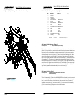
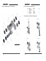
AUTOHRIZED BRAND LOGOS : 2/1/09
MARIN BIKES : CORPORATE BRAND LOGOTYPE
Marin FRS Quad-Link Service Manual
Marin FRS Quad-Link Service Manual
For use on white and light colored backgrounds
12.0: Rear Suspension Set-up - QUAD-Link FRS - Preload
Table of Contents:
These bikes are fitted with either a Fox or an X-Fusion rear air shock unit. The air pressure
in the shock determines the spring rate.
The correct ‘sag’ can be found using the sliding ‘o’ ring fitted to the shaft of the shock piston. Slide the ‘o’ ring against the shock body. Then gently sit on the bike in your normal
riding position. Carefully dismount and measure the distance the ‘o’ ring has moved away
from the shock body.
1.0
Figure 1, Exploded Diagram: Rear Shock Assembly.
For use on black and dark colored backgrounds
1.1
Parts List: Rear Shock Assembly
MARIN BIKES : BOLD STROKE LOGOTYPE & BEAR HEAD ICON
2.0
Removal of Rear Shock
3.0
Figure 2, Exploded Diagram: Rear Suspension Assembly
For use on white and light colored backgrounds
The optimum distance for the QUAD system is 12mm displacement from the ‘o’ ring
back up to the shock body. If there is less than 12mm fit a shock pump and release air
pressure. Conversely if there is greater than 12mm of travel, fit the shock pump and increase air pressure. Repeat the ‘sag’ test until the 12mm displacement is achieved.
3.1
Parts List: Rear Suspension Assembly
4.0
Removal of Swinging Arm
5.0
Removal of Links
6.0
Figure 3, Exploded Diagram: 1 Piece Link Assembly
6.1
Parts List: 1 Piece Link Assembly
For use on black and dark colored backgrounds
LOGOS MAY NOT BE ALTERED IN ANY WAY. If you have any questions or special considerations please contact
."3*/#*,&4t"UUO5PN(PSUPO71#SBOEJOH%FTJHOt 5&-YUt&."*-UPNH!NBSJOCJLFTDPN
12.1: Rear Suspension Set-up - QUAD-Link FRS - Rebound Damping
When the damper unit is being compressed, this is known as the compression stroke. As
the suspension unit recovers from compression back towards its full length, this is called
the re-bound stroke. All the shocks fitted as standard to Marin QUAD-LINK FRS bikes have
factory set compression damping, and manually adjustable rebound damping.
AUTOHRIZED BRAND LOGOS : 2/1/09
Rebound Damping adjustment.
This adjustment fine-tunes the speed at which the rear wheel returns to its normal ride
MARIN BIKES : CORPORATE BRAND LOGOTYPE
height after
hitting a bump. The adjuster is coloured red and is found on the rear damper
unit. An arrow marked slower indicates the direction to turn the dial to slow down the rebound speed of the suspension. To demonstrate the effect of this, turn the adjuster to its
slowest setting. Press down on the saddle to compress the suspension, then release the
load. You will see that the suspension recovers very slowly to its original position.
use on
white and lightService
colored backgrounds
QUAD-LINK
Manual
Repeat the above withForFRS
the
adjuster
turned
to the fastest setting and you will see the
2004 Edition 1
difference immediately the load is released. We recommend the optimum setting is to
adjust the re-bound damping to be as slow as possible, but not so slow that the normal
ride height is not recovered. On very rough terrain, if the rear of the bike becomes
progressively lower as more bumps are hit then the re-bound damping is set too slow. On
the other hand if the bike feels choppy and not plush then the re-bound damping is too
fast. A bit of trial and error is needed to get the exact setting. Riders may choose to
For use stationary,
on black and dark colored
backgrounds
change their settings, while
depending
on the terrain they are riding.
13.0: Front Suspension Set-up
MARIN BIKES : BOLD STROKE LOGOTYPE & BEAR HEAD ICON
When you have set the rear suspension, follow the Owners Manual to fine tune the front
forks. It is important to achieve a balance between the front and rear of the bike. In time,
you will be able to make these small adjustments required to optimise the way in which
the front and rear suspension work together over all types of terrain. In order to achieve
maximum traction, we recommend that it is best to run a small amount of initial “sag” on
For use way
on white
andon
lightthe
colored
backgrounds
the front forks, in the same
as
rear.
7.0
Figure 4a,4b,4c,4d. Illustration of KP5AX Bearing Extraction
7.1
Extracting KP5AX Bearings from 1 Piece Links
8.0
Figure 5, Illustration of KP5AX Bearing Installation
8.1
Parts List: Assembly of KPAX Bearings for Installation
8.2
Installation of KP5AX Bearings
8.3
Figure 6, Diagram of Centre Spacer Installation
8.4
Parts List: Assembly of Centre Spacer Installation
8.5
Installation of Centre Spacer and Remaining KP5AX Bearing
9.0
Figure 7, Illustration of Assembly of Links to Main Frame
9.1
Fitting of Link Assemblies
10.0
Fitting of Swinging Arm
11.0
Fitting of Rear Shock
12.0
Rear Suspension Set-up: Pre-Load
12.1
Rear Suspension Set-up: Rebound Damping
13.0
Front Suspension Set-up
14.0
Torque Settings
15.0
Notes
Page 1
Page 12
2004 Edition 1
For use on black and dark colored backgrounds
Page 1
2004 Edition 1
AUTOHRIZED BRAND LOGOS : 2/1/09
AUTOHRIZED BRAND LOGOS : 2/1/09
MARIN BIKES : CORPORATE BRAND LOGOTYPE
MARIN BIKES : CORPORATE BRAND LOGOTYPE
Marin
FRS
Quad-Link
Service
Manual
Marin
FRS
Quad-Link
Service
Manual
For use on white and light colored backgrounds
1.0:
Figure
Exploded
Diagram
Shock
Assembly.
Ensure
the1,
KP5AX
Bearing
(2) andRear
Link (1)
surfaces
are clean and apply Loctite 641 on the
outside of the KP5AX Bearing (2) and the inside bearing surface of the Link (1). Before
sliding the Center Spacer (3) into position, it is essential that each end of the Center
Spacer (3)
has a large amount of MOLYCOAT grease on both ends to create a donut of the
For use on black and dark colored backgrounds
grease. This will then spread and fill the Labyrinth on assembly. Pass the Centre Spacer (3)
MARIN
BIKES : BOLD STROKE
HEAD taking
ICON
though
theLOGOTYPE
Link& BEAR
(1),
care not to contaminate any bearing surfaces, and locate
against the bearing already pressed in. Using an engineers vice with ‘soft jaws’ to prevent
any damage to the Link, align the Bearing Insertion Tool (9) and Bearing (2) to be pressed
into theForLink
(1) correctly. Press the Bearing (2) into the Link (1), ensuring that the Centre
use on white and light colored backgrounds
Spacer (3) is located in both it’s Labyrinth gaps. Remove any excess Molycoat grease from
around the area. Once all the KP5AX bearings (2) and Link Centre Spacer (3) have been
assembled, the final application of lubricants can be applied before assembly into the Bicycle.
For use on black and dark colored backgrounds
Before re-assembling the Shield Washer Components (4) (5) (6), apply large quantities of
Molycoat Grease on top of the KP5AX Bearings (2) seated in the link (1). The grease should
completely cover each bearing and be applied on both sides of the bearing as it is assembled into the Link (1). Next assemble the Shield Washer Components (4) (5) (6). If you
have applied enough Molycoat grease, grease should spread from under the Shield Washer
component as they are positioned. Wipe excess grease away from around the Shield
Washer Components.
LOGOS MAY NOT BE ALTERED IN ANY WAY. If you have any questions or special considerations please contact
."3*/#*,&4t"UUO5PN(PSUPO71#SBOEJOH%FTJHOt 5&-YUt&."*-UPNH!NBSJOCJLFTDPN
Application of SKF LGAF 3 Compound.
Once the Link has been assembled and correctly greased, SKF LGAF 3 Compound
must be applied to all outside faces of the Shield Washer Components (4) (5) (6)
that contact the Main Frame and Swinging Arm. It is additionally suggested to
apply SKF LGAF 3 compound to the link contact surfaces on the Main Frame and
Swinging Arm.
9.0: Figure 7: Installation of Links onto Mainframe.
Marin
FRS
Quad-Link
Service
Manual
Marin
FRS
Quad-Link
Service
Manual
For use on white and light colored backgrounds
1.1:
PartsofList,
Shock Assembly
9.1
Fitting
LinkRear
Assemblies
to Mainframe. Figure 2
Tools Required:
10mmA/F socket with ratchet or T-Bar drive
5mm A/F Allen Key
wrench
No.Torque
Description
Part Code
Qty
For use on black and dark colored backgrounds
1.
Frame Shock Mount
N/A (Part of Frame)
1
2.
M5 used
x 16 Socket
cap QUAD97-0000
2 the fitting
The
two link assembly’s
(3)
on thehead
MARIN
FRS are identical, as are
MARIN BIKES : BOLD STROKE LOGOTYPE & BEAR HEAD ICON
M5 Washer
Supplied
with No. Both
2
2 are fitted to
procedures, which is3.basically
the reverse of the removal
procedure.
links
4.
Collar
97-3035
2
the bike with the central
crosspiece,
part of the link, on
the bottom of the link
assembly, as
5.
Shaft
97-3036
1
illustrated in Figure 7.
Carefully
slide
the link assembly
(3) onto the main frame
making
6.
Top
Hat
bushes
TOPHAT2012
2
For use on white and light colored backgrounds
sure the shield washers
notbushes
drop out.
Insert screw FOXBUSH4
(4), (70mm), through2the link and
7. do
FOX
(22mm)
main frame (2) replace
(5) and
torque tighten using
the 5mm allen key 1
and torque
8. nut
Glacial
Bearing
FOXBUSH1
wrench. Refer to torque
in section 14.0
9. settings
M6 Sleeve
1
10. FOX bushes (35,5mm)
FOXBUSH5
2
For use on black and dark colored
11.backgrounds
Glacial
Bearing
FOXBUSH1
1
10.0: Fitting
of Swinging
Arm.
Figure 2
12.
Plastic socket
Plug
97-3032
2
Tools Required:
10mmA/F
with ratchet or T-Bar
drive
13.
Nylock
NYLOCKM6
1
5mmM6
A/F
AllenNut
Key
14.
Flat
Washer
WASHERM6
1
4mmM6
A/F
Allen
Key – 2 off
15.
M6 wrench
x 55mm Socket Head Cap M6X55
1
Torque
LOGOS MAY NOT BE ALTERED IN ANY WAY. If you have any questions or special considerations please contact
."3*/#*,&4t"UUO5PN(PSUPO71#SBOEJOH%FTJHOt 5&-YUt&."*-UPNH!NBSJOCJLFTDPN
Offer the swing arm (1) into position with the main frame (2). Align the boss at the front of
the swing arm (1) with the front link assembly (3), making sure the shield washers have
not fallen out. Insert the bolt (6) (85mm), through the washer (7), swing arm (1), main
2.0:
Removal
of Rear
Shock
frame
(2),
swing arm
(1) and
washer (7), replace nut (5) and tighten with the torque
Tools required:
10mmA/F socket with ratchet or T-Bar drive
wrench. Next align the rear boss in the swing arm (1) with the rear link assembly (3) mak5mm A/F Allen Key
ing sure the shield washers
have Allen
not fallen
out.
4mmA/F
Key - 2
off Insert the bolt (6) (85mm), through the
washer (7), swing arm (1), main frame (2), swing arm (1) and washer (7), replace nut (5)
and Support
tighten the
withbike
the by
torque
wrench.
The swing
(1) stand.
shouldRemove
now be the
fixed
to wheel.
the main
clamping
the seat
post inarm
a work
rear
Usframe
should
with
no sideways
movement.
settings,
refer
ing(2)
theand
5mm
Allen move
key tofreely
hold the
Socket
head cap
screw (15)For
andtorque
the 10mm
A/F socket
to section
14.0.
to re-fit
brake
and
check
theythe
arebolt
functioning
to loosen
nutRemember
(13), remove
nut (13)
andassemblies,
washer (14)
then
remove
(15) andcorrectly
before(14)
riding
thethe
bike.
washer
from
other side of the bike. The shock unit should now be disconnected
from the swing arm. Next, in order to remove the shock unit from the main frame (1)
11.0:
of4mm
RearAllen
Shock.
Figure
1 the screws (2). Whichever screw loosens first,
useFitting
the two
keys
to loosen
Tools required:
A/F socket with ratchet or T-bar drive x 2
remove the shaft10mm
(5) from
the opposite side. The shock unit may now be removed from
5mm A/F Allen Key
the bike. Ensure you
the top
4mmcollect
A/F Allen
key hat
x 2 bushes (6) from the shock mount (1) as you
remove the shock.
AUTOHRIZED BRAND LOGOS : 2/1/09
MARIN BIKES : CORPORATE BRAND LOGOTYPE
Basically this is the reverse of the removal procedure. Ensure that the Top Hat Bushes (9)
are installed into the inside of the mainframe mounting point (2). It is best to loosely assemble both ends of the Shock to ensure correct alignment before finally tightening Nut (5)
and Bolts (13). Refer to torque settings in section 14.0. Refit plastic plugs (14)
For use on white and light colored backgrounds
For use on black and dark colored backgrounds
MARIN BIKES : BOLD STROKE LOGOTYPE & BEAR HEAD ICON
Page 2
Page
Page
2 10
For use on white and light colored backgrounds
2004
Edition
2004
Edition
1 1
For use on black and dark colored backgrounds
LOGOS MAY NOT BE ALTERED IN ANY WAY. If you have any questions or special considerations please contact
."3*/#*,&4t"UUO5PN(PSUPO71#SBOEJOH%FTJHOt 5&-YUt&."*-UPNH!NBSJOCJLFTDPN
Page 3
Page
Page
11 3
2004
Edition
2004
Edition
1 1
AUTOHRIZED BRAND LOGOS : 2/1/09
AUTOHRIZED BRAND LOGOS : 2/1/09
MARIN BIKES : CORPORATE BRAND LOGOTYPE
MARIN BIKES : CORPORATE BRAND LOGOTYPE
Marin
FRS
Quad-Link
Service
Manual
Marin
FRS
Quad-Link
Service
Manual
For use on white and light colored backgrounds
3.0:
Figure
2, Exploded
Diagram
Rear
Suspension
Assembly
7.1:
Extraction
of KP5AX
Bearings
from
1 Piece Link
Assembly: Figs 3,4a,4b,4c,4d
Remove all the outer shield washers (4,5,6) and wipe off old grease from the Labyrinth
areas. Assemble
the link as shown in Fig 4a on top of the jaws of an engineer’s vice, supFor use on black and dark colored backgrounds
porting the link whilst allowing the KP5AX bearing to be drifted out between the vice jaws.
Slide
the
M8x65mm
(7) through the top KP5AX bearing, and drift out the Centre
MARIN
BIKES : BOLD
STROKE
LOGOTYPE & BEAR HEADbolt
ICON
Spacer (3) and KP5AX bearing (2) together as shown in figure 4b. Once the Centre Spacer
(3) has been removed from the assembly, the remaining KP5AX bearings can be removed.
To remove
the remaining 3 KP5AX bearings (2) from the one piece link body (1) assemble
For use on white and light colored backgrounds
the components as illustrated in Figure 4c. Using an inner top hat washer (4) seated in the
bearing, slide the M8x65mm bolt (7) through the top KP5AX bearing, and repeat the procedure to drift out the lower KP5AX bearing. Once these bearings have been removed, it
should be possible to remove the remaining two KP5AX bearings with a normal size drift
For use on black and dark colored backgrounds
tool.
LOGOS MAY NOT BE ALTERED IN ANY WAY. If you have any questions or special considerations please contact
Marin
FRS
Quad-Link
Service
Manual
Marin
FRS
Quad-Link
Service
Manual
For use on white and light colored backgrounds
Part
List,
Rear
Suspension
Figure
It 3.1:
is vital
the
Link
Spacer
Tool (8)Assembly:
is placed here
to 2
prevent bending of the One
Piece Link during installation of the Bearings. Apply Loctite 641 on the outside of the
Part Code
KP5AX bearing (2)No.
and onDescription
the inside bearing surface
of the Link (1). UsingQty
the Bearing
1.
Swing Arm
1
insertion Tool
(9),
assemble
For use on
black and dark
colored backgrounds as shown in figure 5 using an engineers vice with ‘soft jaws’ to
2.
Main Frame
1
prevent any damage
Link.
Align the components and press the bearing
3. to theLink
Assembly
2 into the link.
MARIN BIKES the
: BOLD STROKE
LOGOTYPE & presses
BEAR HEAD ICON in squarely, and is correctly seated in the bottom of it’s housEnsure
bearing
4.
M6 Cap Head Bolt
BOLTM6x70-4B
2
ing. Repeat until three
are installed.
The final bearing will require
the Cen5. KP5AX
Nylocbearing
nut
M6 Nyloc
5
6. at the
M6 Cap
Head
Boltas pressing
BOLTM6x85-4B
2
ter Spacer to be fitted
same
time
the bearing in.
7.
Washer
M6 Washer
6
8.
Screw socket head cap BOLTM6x55-4B
1
9.
hat bush
TOPHAT2012
2
8.3 Figure 6: Diagram
ofTop
KP5AX
Bearing and
Centre Spacer Installation
10.
Shaft
CRO3036
1
11.
Collar
97-3035
2
12.
Washer
M5 Washer
2
For use on black and dark colored backgrounds
13.
Screw socket head cap M5 x 16
2
14.
Plastic Plug
97-3032
4
For use on white and light colored backgrounds
LOGOS MAY NOT BE ALTERED IN ANY WAY. If you have any questions or special considerations please contact
."3*/#*,&4t"UUO5PN(PSUPO71#SBOEJOH%FTJHOt 5&-YUt&."*-UPNH!NBSJOCJLFTDPN
."3*/#*,&4t"UUO5PN(PSUPO71#SBOEJOH%FTJHOt 5&-YUt&."*-UPNH!NBSJOCJLFTDPN
8.0: Figure 5: Diagram of KP5AX Bearing Installation
Not Pictured:
Fox shock
Air Vanilla Float R 35.5/22 1
4.0: Removal of Swinging Arm. Figure 2
Tools required:
To remove the swinging arm from the bike, follow the procedure to remove the shock unit
(Section 2.0). Next remove the rear disc brake calliper from the drop-out, and detach hose
from the stops. Do not allow calliper to dangle unsupported by it’s hose. Remove rear derailleur mechanism from the swing arm (1). Next remove the two Plastic Plugs (14). Now
using the 5mm Allen key to hold the bolt (6) at the front of the swing arm (1) and using
the 10mm A/F socket loosen and remove the nut (5) and washer (7), now remove the bolt
(6) and washer (7). The swing arm (1) should now be released form the front link. Next
use the 5mm Allen key to hold the bolt (6), in the swing arm (1) just behind the seat tube,
use the 10mm A/F socket loosen and remove the nut (5) and washer (7), now remove the
8.4: Parts List. Centre Spacer and KP5AX Bearing Installation into 1 Piece Link.
bolt (6) and washer (7). It should now be possible to remove the Swinging arm (1) by lifting it vertically upwards
then forwards away from the main frame Qty.
(2).
No.
Description
8.1: Part List. KP5AX Bearing Installation into 1 Piece Link.
No.
1
2
3
MARIN BIKES : CORPORATE BRAND LOGOTYPE
8
9
Description
AUTOHRIZED BRAND LOGOS : 2/1/09
35mm 1 Piece Link
KP5AX Bearing
Centre Spacer
Link Spacer Tool
Bearing Insertion Tool
4mm A/F & 5mm A/F Allen keys
1
35mm/1 Piece Link
2
KP5AX Bearing
3
Centre Spacer
5.0: Removal of Links.
Figure
2
8 10mmA/F
Link Spacer
Tool
Tools Required:
socket
with ratchet or T-Bar drive
9 5mmBearing
Insertion
A/F Allen
Key Tool
Qty.
2
4
1
1
1
For use on white and light colored backgrounds
8.2: Installation of KP5AX Bearings into One Piece Link
To install the KP5AX (2) bearings into the links, first ensure all bearing surfaces and faces
are free from grease old retaining compound and all other contamination. Slide the Link
For use on black and dark colored backgrounds
spacer tool (8) in between the inner faces of the One Piece Link (1), as shown in Figure 5.
2
4
1
1
1
The two link assembly’s (3) used on the MARIN QUAD FRS are identical, as are the removal
8.5
Installation
of KP5AX
Bearing
and Centre
Spacer
procedures.
Having
followed
the procedures
above
to remove the shock unit and swinging
arm (1), use the 5mm Allen key to hold the bolt (4) then use the 10mm A/F socket to
The
final and
bearing
will require
Spacer the
(3) bolt
to be(4),
fitted
the same
pressloosen
remove
the nut the
(5),Center
next remove
nowatremove
thetime
link as
assembly
ing(3)
the
bearing
in. Place
the Link
Spacer
Tool
in between
the One Piece Link (1) as
from
the main
frame(2),
taking
care
not(8)
to drop
the washers.
shown in Figure 6. It is vital the Link Spacer Tool (8) is placed here to prevent
bending of the One Piece Link during installation of the Bearing.
MARIN BIKES : BOLD STROKE LOGOTYPE & BEAR HEAD ICON
Page 4
Page
Page
4 8
Page 5
For use on white and light colored backgrounds
For use on black and dark colored backgrounds
2004
Edition
2004
Edition
1 1
Page
Page
9 5
2004
Edition
2004
Edition
1 1
AUTOHRIZED BRAND LOGOS : 2/1/09
AUTOHRIZED BRAND LOGOS : 2/1/09
MARIN BIKES : CORPORATE BRAND LOGOTYPE
MARIN BIKES : CORPORATE BRAND LOGOTYPE
Marin
MarinFRS
FRSQuad-Link
Quad-LinkService
ServiceManual
Manual
Marin
MarinFRS
FRSQuad-Link
Quad-LinkService
ServiceManual
Manual
For use on white and light colored backgrounds
For use on white and light colored backgrounds
6.0:
6.0:
Figure
Figure
3,3,
Exploded
Exploded
Diagram
Diagram
11
Piece
Piece
Link
Link
Assembly
Assembly
6.1:
6.1:
Parts
Parts
List:
List:
11
Piece
Piece
Link
Link
Assembly.
Assembly.
Figure
Figure
33
No.
No. Description
Description
1. 1.
1 Piece
1 Piece
Link
Link
body
body
2. 2.
KP5AX
KP5AX
Bearing
Bearing
3. &3.
CentreSpacer
MARIN BIKES : BOLD STROKE LOGOTYPE
BEAR HEADCentreSpacer
ICON
4. 4.
Shield
Shield
washer
washer
5. 5.
Shield
Shield
washer
washer
6. 6.
Shield
Shield
washer
washer
For use on black and dark colored backgrounds
For use on black and dark colored backgrounds
MARIN BIKES : BOLD STROKE LOGOTYPE & BEAR HEAD ICON
For use on white and light colored backgrounds
Part
Part
Code
Code
Qty
Qty
1 1
4 4
1 1
2 2
2 2
2 2
KP5A
KP5A
Spacer4B
Spacer4B
Washin4B
Washin4B
Washpl4B
Washpl4B
Washout4B
Washout4B
For use on white and light colored backgrounds
7.0:
7.0:
Figures
Figures
4a,4b,4c,4d,
4a,4b,4c,4d,
Illustration
Illustration
ofof
Bearing
Bearing
Removal
Removal
For use on black and dark colored backgrounds
For use on black and dark colored backgrounds
Figure
Figure
4a:
4a:
LOGOS MAY NOT BE ALTERED IN ANY WAY. If you have any questions or special considerations please contact
LOGOS MAY NOT BE ALTERED IN ANY WAY. If you have any questions or special considerations please contact
."3*/#*,&4t"UUO5PN(PSUPO71#SBOEJOH%FTJHOt 5&-YUt&."*-UPNH!NBSJOCJLFTDPN
."3*/#*,&4t"UUO5PN(PSUPO71#SBOEJOH%FTJHOt 5&-YUt&."*-UPNH!NBSJOCJLFTDPN
Figure
Figure
4c4c
Figure
Figure
4b:
4b:
Figure
Figure
4d4d
AUTOHRIZED BRAND LOGOS : 2/1/09
MARIN BIKES : CORPORATE BRAND LOGOTYPE
For use on white and light colored backgrounds
For use on black and dark colored backgrounds
MARIN BIKES : BOLD STROKE LOGOTYPE & BEAR HEAD ICON
Page 6
Page
Page
6 6
Page 7
For use on white and light colored backgrounds
2004
2004
Edition
Edition
1 1
For use on black and dark colored backgrounds
LOGOS MAY NOT BE ALTERED IN ANY WAY. If you have any questions or special considerations please contact
."3*/#*,&4t"UUO5PN(PSUPO71#SBOEJOH%FTJHOt 5&-YUt&."*-UPNH!NBSJOCJLFTDPN
Page
Page
7 7
2004
2004
Edition
Edition
1 1
AUTOHRIZED BRAND LOGOS : 2/1/09
AUTOHRIZED BRAND LOGOS : 2/1/09
MARIN BIKES : CORPORATE BRAND LOGOTYPE
MARIN BIKES : CORPORATE BRAND LOGOTYPE
Marin
FRS
Quad-Link
Service
Manual
Marin
FRS
Quad-Link
Service
Manual
For use on white and light colored backgrounds
3.0:
Figure 2, of
Exploded
Diagram from
Rear 1
Suspension
7.1:
Extraction
KP5AX Bearings
Piece Link Assembly
Assembly: Figs 3,4a,4b,4c,4d
Remove all the outer shield washers (4,5,6) and wipe off old grease from the Labyrinth
areas. Assemble
the
as shown in Fig 4a on top of the jaws of an engineer’s vice, supFor use on black and dark
coloredlink
backgrounds
porting the link whilst allowing the KP5AX bearing to be drifted out between the vice jaws.
MARIN BIKESthe
: BOLD STROKE
LOGOTYPE & BEAR bolt
HEAD ICON(7) through the top KP5AX bearing, and drift out the Centre
Slide
M8x65mm
Spacer (3) and KP5AX bearing (2) together as shown in figure 4b. Once the Centre Spacer
(3) has been removed from the assembly, the remaining KP5AX bearings can be removed.
To remove
the remaining 3 KP5AX bearings (2) from the one piece link body (1) assemble
For use on white and light colored backgrounds
the components as illustrated in Figure 4c. Using an inner top hat washer (4) seated in the
bearing, slide the M8x65mm bolt (7) through the top KP5AX bearing, and repeat the procedure to drift out the lower KP5AX bearing. Once these bearings have been removed, it
should be Forpossible
to remove the remaining two KP5AX bearings with a normal size drift
use on black and dark colored backgrounds
tool.
LOGOS MAY NOT BE ALTERED IN ANY WAY. If you have any questions or special considerations please contact
Marin
FRS
Quad-Link
Service
Manual
Marin
FRS
Quad-Link
Service
Manual
For use on white and light colored backgrounds
It is
vital
theRear
LinkSuspension
Spacer ToolAssembly:
(8) is placed
here
3.1:
Part
List,
Figure
2 to prevent bending of the One
Piece Link during installation of the Bearings. Apply Loctite 641 on the outside of the
Description
Partsurface
Code of the Link (1). Using
Qty the Bearing
KP5AX bearingNo.
(2) and
on the inside bearing
1. assemble
Swing Arm
1 with ‘soft jaws’ to
insertion ForTool
(9),
as shown in figure 5 using an engineers vice
use on black
and dark colored
backgrounds
2.
Main
1
prevent any damage
to
theFrame
Link. Align the components and press the bearing
into the link.
3.
Link Assembly
2
MARIN BIKES : BOLD
STROKE
LOGOTYPE & BEARpresses
HEAD ICON
Ensure
the
bearing
in squarely, and is correctly seated in the bottom of it’s hous4.
M6 Cap Head Bolt
BOLTM6x70-4B
2
ing. Repeat until
KP5AX
5. threeNyloc
nutbearing are installed.
M6 Nyloc The final bearing will
5 require the Center Spacer to be
atCap
theHead
sameBolt
time asBOLTM6x85-4B
pressing the bearing in.
6. fittedM6
2
7.
Washer
M6 Washer
6
8.
Screw socket head cap BOLTM6x55-4B
1
9.
Topof
hat
bush Bearing
TOPHAT2012
2
8.3 Figure 6: Diagram
KP5AX
and Centre Spacer Installation
10.
Shaft
CRO3036
1
11.
Collar
97-3035
2
For use on black and
dark colored backgrounds
12.
Washer
M5 Washer
2
13.
Screw socket head cap M5 x 16
2
14.
Plastic Plug
97-3032
4
For use on white and light colored backgrounds
LOGOS MAY NOT BE ALTERED IN ANY WAY. If you have any questions or special considerations please contact
."3*/#*,&4t"UUO5PN(PSUPO71#SBOEJOH%FTJHOt 5&-YUt&."*-UPNH!NBSJOCJLFTDPN
."3*/#*,&4t"UUO5PN(PSUPO71#SBOEJOH%FTJHOt 5&-YUt&."*-UPNH!NBSJOCJLFTDPN
8.0: Figure 5: Diagram of KP5AX Bearing Installation
Not Pictured:
Fox shock
Air Vanilla Float R 35.5/22 1
4.0: Removal of Swinging Arm. Figure 2
Tools required:
AUTOHRIZED BRAND LOGOS : 2/1/09
MARIN BIKES : CORPORATE BRAND LOGOTYPE
For use on white and light colored backgrounds
8.1: Part List. KP5AX Bearing Installation into 1 Piece Link.
No.
1
2
3
8
9
Description
35mm 1 Piece Link
KP5AX Bearing
Centre Spacer
Link Spacer Tool
Bearing Insertion Tool
Qty.
2
4
MARIN BIKES : BOLD STROKE LOGOTYPE & BEAR HEAD ICON
1
1
1
For use on black and dark colored backgrounds
For use on white and light colored backgrounds
8.2: Installation of KP5AX Bearings into One Piece Link
4mm A/F & 5mm A/F Allen keys
AUTOHRIZED BRAND LOGOS : 2/1/09
To remove the swinging arm from the bike, follow the procedure to remove the shock
unit
(Section 2.0). Next remove the rear disc brake calliper from the drop-out, and detach hose
from the stops. Do not allow calliper to dangle unsupported byMARIN
it’s
BIKEShose.
: CORPORATERemove
BRAND LOGOTYPE rear derailleur mechanism from the swing arm (1). Next remove the two Plastic Plugs (14). Now
using the 5mm Allen key to hold the bolt (6) at the front of the swing arm (1) and using
the 10mm A/F socket loosen and remove the nut (5) and washer (7), now remove the bolt
For use on white and light colored backgrounds
(6) and washer (7). The swing arm (1) should now be released form the front link. Next
use the 5mm Allen key to hold the bolt (6), in the swing arm (1) just behind the seat tube,
use
theParts
10mmList.
A/F Centre
socket loosen
and
remove
theBearing
nut (5) Installation
and washer (7),
now
remove
the
8.4:
Spacer
and
KP5AX
into
1 Piece
Link.
bolt (6) and washer (7). It should now be possible to remove the Swinging arm (1) by liftFor use on black and dark colored backgrounds
ing it vertically upwards
forwards away from the main frame (2). Qty.
No.thenDescription
1
35mm/1 Piece Link
2
MARIN BIKES : BOLD STROKE LOGOTYPE & BEAR HEAD ICON
2
KP5AX Bearing
4
3 Figure
Centre
1
5.0: Removal of Links.
2 Spacer
8
Link
Spacer
Tool
1
Tools Required:
10mmA/F
socket
with
ratchet or T-Bar drive
9 A/FBearing
Insertion Tool
1
5mm
Allen Key
For use on white and light colored backgrounds
The two link assembly’s (3) used on the MARIN QUAD FRS are identical, as are the removal
8.5 Installation of KP5AX Bearing and Centre Spacer
procedures. Having followed the procedures above to remove the shock unit and swinging
arm (1), use the 5mm Allen key to hold the bolt (4) then use the 10mm
A/F
socket
to
For use
on black and
dark colored backgrounds
The final bearing will require the Center Spacer (3) to be fitted at the same time as pressloosen and remove the nut (5), next remove the bolt (4), now remove the link assembly
ing the bearing in. Place the Link Spacer Tool (8) in between the One Piece Link (1) as
(3) from the main frame(2), taking care not to drop the washers.
shown in Figure 6. It is vital the Link Spacer Tool (8) is placed here to prevent
bending of the One Piece Link during installation of the Bearing.
LOGOS MAY NOT BE ALTERED IN ANY WAY. If you have any questions or special considerations please contact
To install the KP5AX (2) bearings into the links, first ensure all
bearing surfaces and faces
For use on black and dark colored backgrounds
are free from grease old retaining compound and all other contamination. Slide the Link
spacer tool (8) in between the inner faces of the One Piece Link (1), as shown in Figure 5.
."3*/#*,&4t"UUO5PN(PSUPO71#SBOEJOH%FTJHOt 5&-YUt&."*-UPNH!NBSJOCJLFTDPN
LOGOS MAY NOT BE ALTERED IN ANY WAY. If you have any questions or special considerations please contact
."3*/#*,&4t"UUO5PN(PSUPO71#SBOEJOH%FTJHOt 5&-YUt&."*-UPNH!NBSJOCJLFTDPN
Page 8
Page
Page
8 4
Page 9
2004
Edition
2004
Edition
1 1
Page
Page
5 9
2004
Edition
2004
Edition
1 1
AUTOHRIZED BRAND LOGOS : 2/1/09
AUTOHRIZED BRAND LOGOS : 2/1/09
MARIN BIKES : CORPORATE BRAND LOGOTYPE
MARIN BIKES : CORPORATE BRAND LOGOTYPE
MarinFRS
FRSQuad-Link
Quad-LinkService
ServiceManual
Manual
Marin
For use on white and light colored backgrounds
1.0: Figure 1, Exploded Diagram Rear Shock Assembly.
Ensure the KP5AX Bearing (2) and Link (1) surfaces are clean and apply Loctite 641 on the
outside of the KP5AX Bearing (2) and the inside bearing surface of the Link (1). Before
sliding the Center Spacer (3) into position, it is essential that each end of the Center
Spacer (3)
adarklarge
amount of MOLYCOAT grease on both ends to create a donut of the
For usehas
on black and
colored backgrounds
grease. This will then spread and fill the Labyrinth on assembly. Pass the Centre Spacer (3)
MARIN
BIKES : BOLD
STROKELink
LOGOTYPE(1),
& BEAR HEAD
ICON
though
the
taking
care not to contaminate any bearing surfaces, and locate
against the bearing already pressed in. Using an engineers vice with ‘soft jaws’ to prevent
any damage to the Link, align the Bearing Insertion Tool (9) and Bearing (2) to be pressed
into the Link
(1) correctly. Press the Bearing (2) into the Link (1), ensuring that the Centre
For use on white and light colored backgrounds
Spacer (3) is located in both it’s Labyrinth gaps. Remove any excess Molycoat grease from
around the area. Once all the KP5AX bearings (2) and Link Centre Spacer (3) have been
assembled, the final application of lubricants can be applied before assembly into the Bicycle.
For use on black and dark colored backgrounds
Before re-assembling the Shield Washer Components (4) (5) (6), apply large quantities of
Molycoat Grease on top of the KP5AX Bearings (2) seated in the link (1). The grease should
completely cover each bearing and be applied on both sides of the bearing as it is assembled into the Link (1). Next assemble the Shield Washer Components (4) (5) (6). If you
have applied enough Molycoat grease, grease should spread from under the Shield Washer
component as they are positioned. Wipe excess grease away from around the Shield
Washer Components.
LOGOS MAY NOT BE ALTERED IN ANY WAY. If you have any questions or special considerations please contact
."3*/#*,&4t"UUO5PN(PSUPO71#SBOEJOH%FTJHOt 5&-YUt&."*-UPNH!NBSJOCJLFTDPN
Application of SKF LGAF 3 Compound.
Once the Link has been assembled and correctly greased, SKF LGAF 3 Compound
must be applied to all outside faces of the Shield Washer Components (4) (5) (6)
that contact the Main Frame and Swinging Arm. It is additionally suggested to
apply SKF LGAF 3 compound to the link contact surfaces on the Main Frame and
Swinging Arm.
9.0: Figure 7: Installation of Links onto Mainframe.
For use on white and light colored backgrounds
For use on black and dark colored backgrounds
Page 10
MARIN BIKES : BOLD STROKE LOGOTYPE & BEAR HEAD ICON
For use on black and dark colored backgrounds
10mmA/F socket with ratchet or T-Bar drive
5mm A/F Allen Key
Torque wrench
No.
Description
Part Code
Qty
For use on black and dark colored backgrounds
1.
Frame Shock Mount
N/A (Part of Frame)
1
The
two link assembly’s
onhead
the MARIN
QUAD
FRS are identical, 2as are the fitting
2.
M5 (3)
x 16used
Socket
cap
97-0000
MARIN BIKES : BOLD STROKE LOGOTYPE & BEAR HEAD ICON
procedures, which
the reverse of the removal
3. is basically
M5 Washer
Supplied procedure.
with No. 2 Both
2 links are fitted to
Collar
97-3035
2 link assembly, as
the bike with the 4.
central
crosspiece, part of the link,
on the bottom of the
5. 7. Shaft
97-3036
illustrated in Figure
Carefully slide the link assembly
(3) onto the main1 frame making
6.colored backgrounds
Top
bushes
TOPHAT2012
2
For use on white and light
sure the shield
washers
doHat
not
drop out. Insert screw
(4), (70mm), through
the link and
7.
FOX bushes (22mm)
FOXBUSH4
2
main frame (2) replace
nut
(5)
and
torque
tighten
using
the
5mm
allen
key
and torque
8.
Glacial Bearing
FOXBUSH1
1
wrench. Refer to 9.
torque
M6settings
Sleeve in section 14.0
1
10. FOX bushes (35,5mm)
FOXBUSH5
2
For use on blackof
and dark
colored backgrounds
10.0: Fitting
Swinging
Figure 2
11.
Glacial Arm.
Bearing
FOXBUSH1
1
Plastic Plugsocket with ratchet97-3032
2
Tools Required: 12. 10mmA/F
or T-Bar drive
A/F Allen
13. 5mm
M6 Nylock
Nut Key
NYLOCKM6
1
A/F
Allen Key – 2 off
14. 4mm
M6 Flat
Washer
WASHERM6
1
wrench
15. Torque
M6 x 55mm
Socket Head Cap M6X55
1
LOGOS MAY NOT BE ALTERED IN ANY WAY. If you have any questions or special considerations please contact
."3*/#*,&4t"UUO5PN(PSUPO71#SBOEJOH%FTJHOt 5&-YUt&."*-UPNH!NBSJOCJLFTDPN
Offer the swing arm (1) into position with the main frame (2). Align the boss at the front of
the swing arm (1) with the front link assembly (3), making sure the shield washers have
not fallen out. Insert the bolt (6) (85mm), through the washer (7), swing arm (1), main
2.0: Removal
of Rear
Shock
frame
(2), swing
arm (1)
and washer (7), replace nut (5) and tighten with the torque
Tools required:
10mmA/F
ratchet
or T-Bar
drive
wrench.
Next align the
rear bosssocket
in thewith
swing
arm (1)
with the
rear link assembly (3) mak5mm A/F
Allen
Key
ing sure the shield washers
have
not
fallen out. Insert the bolt (6) (85mm), through the
4mmA/F Allen Key - 2 off
washer (7), swing arm (1), main frame (2), swing arm (1) and washer (7), replace nut (5)
and tighten with the torque wrench. The swing arm (1) should now be fixed to the main
Support the bike by clamping the seat post in a work stand. Remove the rear wheel. Usframe (2) and should move freely with no sideways movement. For torque settings, refer
ing the 5mm Allen key to hold the Socket head cap screw (15) and the 10mm A/F socket
to section 14.0. Remember to re-fit brake assemblies, and check they are functioning corto loosen nut (13), remove nut (13) and washer (14) then remove the bolt (15) and
rectly before riding the bike.
washer (14) from the other side of the bike. The shock unit should now be disconnected
from the swing arm. Next, in order to remove the shock unit from the main frame (1)
11.0: Fitting of Rear Shock. Figure 1
use the
two 4mm Allen
keysA/F
to socket
loosen with
the screws
Whichever
loosens first,
Tools
required:
10mm
ratchet(2).
or T-bar
drive xscrew
2
remove the shaft (5)5mm
fromA/F
the Allen
opposite
Key side. The shock unit may now be removed from
the bike. Ensure you 4mm
collect
the
top key
hat x
bushes
(6) from the shock mount (1) as you
A/F
Allen
2
remove the shock.
Basically this is the reverse of the removal procedure. Ensure that the Top Hat Bushes (9)
are installed into the inside of the mainframe mounting point (2). It is best to loosely assemble both ends of the Shock to ensure correct alignment before finally tightening Nut (5)
and Bolts (13). Refer to torque settings in section 14.0. Refit plastic plugs (14)
For use on white and light colored backgrounds
For use on black and dark colored backgrounds
Page 11
MARIN BIKES : BOLD STROKE LOGOTYPE & BEAR HEAD ICON
2004
Edition
2004
Edition
1 1
For use on white and light colored backgrounds
For use on black and dark colored backgrounds
LOGOS MAY NOT BE ALTERED IN ANY WAY. If you have any questions or special considerations please contact
LOGOS MAY NOT BE ALTERED IN ANY WAY. If you have any questions or special considerations please contact
."3*/#*,&4t"UUO5PN(PSUPO71#SBOEJOH%FTJHOt 5&-YUt&."*-UPNH!NBSJOCJLFTDPN
Tools Required:
MARIN BIKES : CORPORATE BRAND LOGOTYPE
Page
Page
102
For use on white and light colored backgrounds
9.1Parts
Fitting
of Link
to Mainframe. Figure 2
1.1:
List,
RearAssemblies
Shock Assembly
AUTOHRIZED BRAND LOGOS : 2/1/09
AUTOHRIZED BRAND LOGOS : 2/1/09
MARIN BIKES : CORPORATE BRAND LOGOTYPE
MarinFRS
FRSQuad-Link
Quad-LinkService
ServiceManual
Manual
Marin
For use on white and light colored backgrounds
."3*/#*,&4t"UUO5PN(PSUPO71#SBOEJOH%FTJHOt 5&-YUt&."*-UPNH!NBSJOCJLFTDPN
Page
Page
3 11
2004
Edition
2004
Edition
1 1
AUTOHRIZED BRAND LOGOS : 2/1/09
AUTOHRIZED BRAND LOGOS : 2/1/09
MARIN BIKES : CORPORATE BRAND LOGOTYPE
MARIN BIKES : CORPORATE BRAND LOGOTYPE
Marin
MarinFRS
FRSQuad-Link
Quad-LinkService
ServiceManual
Manual
Marin FRS Quad-Link Service Manual
For use on white and light colored backgrounds
For use on white and light colored backgrounds
14.0: Torque Settings
12.0: Rear Suspension Set-up - QUAD-Link FRS - Preload
AUTOHRIZED BRAND LOGOS : 2/1/09
These bikes are fitted with either a Fox or an X-Fusion rear air shock unit. The air pressure
in the shock
determines
the spring rate.
For use on
black and dark colored backgrounds
MARIN BIKES
: BOLD STROKE
LOGOTYPE can
& BEAR HEAD
The
correct
‘sag’
beICONfound using the sliding ‘o’ ring fitted to the shaft of the shock piston. Slide the ‘o’ ring against the shock body. Then gently sit on the bike in your normal
riding position. Carefully dismount and measure the distance the ‘o’ ring has moved away
from the shock
body.
For use on white and light colored backgrounds
The optimum distance for the QUAD system is 12mm displacement from the ‘o’ ring
back up to the shock body. If there is less than 12mm fit a shock pump and release air
pressure. ForConversely
if there is greater than 12mm of travel, fit the shock pump and inuse on black and dark colored backgrounds
crease air pressure. Repeat the ‘sag’ test until the 12mm displacement is achieved.
Table of Contents:
MARIN BIKES : CORPORATE BRAND LOGOTYPE
1.0
Figure 1, Exploded Diagram: Rear Shock Assembly.
For use on black and dark colored backgrounds
QUAD-LINK REAR SUSPENSION
1.1
Parts List: Rear Shock Assembly
For use on white and light colored backgrounds
2.0
Removal of Rear Shock
3.0
Figure 2, Exploded Diagram: Rear Suspension Assembly
SHOCK REAR PIVOT BOLT (8)
lbs.ft
8.0
6.0
5.5
4.0
8.0
6.0
8.0
6.0
For use on black and dark colored backgrounds
For use on white and light colored backgrounds
3.1
Parts List: Rear Suspension Assembly
4.0
Removal of Swinging Arm
SHOCK FRONT MOUNTING BOLTS (13)
MARIN BIKES : BOLD STROKE LOGOTYPE & BEAR HEAD ICON
For use on white and light colored backgrounds
5.0
Removal of Links
For use on black and dark colored backgrounds
SWING ARM - TO - LINK THROUGH BOLT M6x85mm (6)
LOGOS MAY NOT BE ALTERED IN ANY WAY. If you have any questions or special considerations please contact
LOGOS MAY NOT BE ALTERED IN ANY WAY. If you have any questions or special considerations please contact
."3*/#*,&4t"UUO5PN(PSUPO71#SBOEJOH%FTJHOt 5&-YUt&."*-UPNH!NBSJOCJLFTDPN
."3*/#*,&4t"UUO5PN(PSUPO71#SBOEJOH%FTJHOt 5&-YUt&."*-UPNH!NBSJOCJLFTDPN
12.1: Rear Suspension Set-up - QUAD-Link FRS - Rebound Damping
6.0
Figure 3, Exploded Diagram: 1 Piece Link Assembly
6.1
Parts List: 1 Piece Link Assembly
For use on black and dark colored backgrounds
When the damper unit is being compressed, this is known as the compression stroke. As
the suspension unit recovers from compression back towards its full length, this is called
the re-bound stroke. All the shocks fitted as standard to Marin QUAD-LINK FRS bikes have
factory set compression damping, and manually adjustable rebound damping.
LINK - TO - MAIN FRAME THROUGH BOLT M6x70mm (4)
LOGOS MAY NOT BE ALTERED IN ANY WAY. If you have any questions or special considerations please contact
."3*/#*,&4t"UUO5PN(PSUPO71#SBOEJOH%FTJHOt 5&-YUt&."*-UPNH!NBSJOCJLFTDPN
7.0
Figure 4a,4b,4c,4d. Illustration of KP5AX Bearing Extraction
7.1
Extracting KP5AX Bearings from 1 Piece Links
8.0
Figure 5, Illustration of KP5AX Bearing Installation
8.2
Installation of KP5AX Bearings
8.3
Figure 6, Diagram of Centre Spacer Installation
8.4
Parts List: Assembly of Centre Spacer Installation
8.5
Installation of Centre Spacer and Remaining KP5AX Bearing
9.0
Figure 7, Illustration of Assembly of Links to Main Frame
9.1
Fitting of Link Assemblies
10.0
Fitting of Swinging Arm
11.0
Fitting of Rear Shock
12.0
Rear Suspension Set-up: Pre-Load
12.1
Rear Suspension Set-up: Rebound Damping
13.0: Front Suspension Set-up
13.0
Front Suspension Set-up
When you have set the rear suspension, follow the Owners Manual to fine tune the front
forks. It is important to achieve a balance between the front and rear of the bike. In time,
you will be able to make these small adjustments required to optimise the way in which
the front and rear suspension work together over all types of terrain. In order to achieve
maximum traction, we recommend that it is best to run a small amount of initial “sag” on
the front forks, in the same way as on the rear.
14.0
Torque Settings
15.0
Notes
Torque explained: If no suitable Torque Wrench is available a Torque of 6 lbf.ft can be obtained by applying a force 8.1
of 6lb, with
Spring
Balance,
to theBearings
end of afor1 Installation
Foot long wrench.
PartsaList:
Assembly
of KPAX
Rebound Damping adjustment.
This adjustment fine-tunes the speed at which the rear wheel returns to its normal ride
height after hitting a bump. The adjuster is coloured red and is found on the rear damper
unit. An arrow marked slower indicates the direction to turn the dial to slow down the rebound speed of the suspension. To demonstrate the effect of this, turn the adjuster to its
slowest setting. Press down on the saddle to compress the suspension, then release the
load. You will see that the suspension recovers very slowly to its original position.
15.0: Notes
Repeat the above with the adjuster turned to the fastest setting and you will see the
difference immediately the load is released. We recommend the optimum setting is to
adjust the re-bound damping to be as slow as possible, but not so slow that the normal
ride height is not recovered. On very rough terrain, if the rear of the bike becomes
progressively lower as more bumps are hit then the re-bound damping is set too slow. On
the other hand if the bike feels choppy and not plush then the re-bound damping is too
fast. A bit of trial and error is needed to get the exact setting. Riders may choose to
change their settings, while stationary, depending on the terrain they are riding.
Page 12
Page 12
Nm
MARIN BIKES : BOLD STROKE LOGOTYPE & BEAR HEAD ICON
Page 13
2004 Edition 1
Page
Page
1 13
2004
Edition
2004
Edition
1 1


![TSE Series - User Manual [ES]](http://vs1.manualzilla.com/store/data/006232823_1-6e8b23ae158bff6df1360bba873002cc-150x150.png)