1
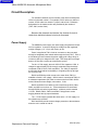
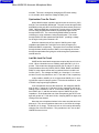
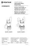
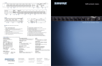
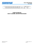
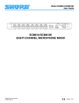
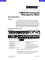
Previous
Products
Service Manual
AMS8100 Automatic
Microphone Mixer
Characteristics
General
The AMS8100 is an automatic microphone mixer using Shure’s
patented Directional Intellimixr that activates only those microphones
being addressed, minimizing poor audio caused by multiple open microphones. Each AMS8100 is an eight-channel microphone mixer capable
of handling up to eight AMS microphones and two aux-level sources and
can be expanded for installations as large as 400 input channels. The
AMS8100 microphone mixer works only with Shure AMS microphones
and can be linked with Shure’s SCM810 and FP410 automatic mixers.
Controls and Connectors
ÁÁÁÁÁÁ
ÁÁÁÁÁÁÁÁÁÁÁÁÁÁÁÁÁÁÁÁÁÁÁ
ÁÁ
Á
Á
ÁÁÁÁ
Á
ÁÁ
Á
ÁÁ
ÁÁÁ
Á
ÁÁ
Á
ÁÁ
Á
ÁÁ
Á
ÁÁÁ
Á
ÁÁ
Á
ÁÁÁ
ÁÁ
Á
ÁÁ
Á
ÁÁ
Á
ÁÁ
Á
ÁÁ
Á
ÁÁ
Á
ÁÁÁ
Á
Á
Á
Á
ÁÁ
Á
Á
Á
ÁÁÁ
Á
Á
ÁÁ
Á
Á
Á
Á
ÁÁÁÁ
ÁÁ
ÁÁ
Á
Á
ÁÁ
ÁÁ
Á
Á
ÁÁ
ÁÁ
Á
Á
Á
Á
Á
Á
ÁÁ
Á
ÁÁ
ÁÁ
ÁÁ
Á
Á
Á
Á
ÁÁ
Á
Á
Á
ÁÁ
ÁÁ
Á
Á
Á
Á
Á
Á
Á
Á
Á
Á
Á
Á
Á
ÁÁ
ÁÁ
ÁÁ
ÁÁ
ÁÁ
ÁÁ
Á
Á
ÁÁ
ÁÁ
ÁÁ
ÁÁ
ÁÁ
ÁÁ
ÁÁ
ÁÁ
ÁÁÁÁÁ
Á
ÁÁÁÁÁÁÁÁÁÁÁÁÁÁÁÁÁÁÁÁÁÁÁÁÁÁÁÁÁ
ÁÁÁ
ÁÁÁ
ÁÁÁÁÁÁ
ÁÁÁÁÁÁ
ÁÁÁ
ÁÁÁÁÁ
ÁÁ
ÁÁÁÁ
ÁÁÁ
ÁÁÁ
ÁÁ
ÁÁÁÁÁ
ÁÁÁÁÁ
ÁÁ
ÁÁÁÁ
ÁÁÁ
ÁÁ
Á
Á
ÁÁ
Á
ÁÁ
Á
Á
ÁÁ
ÁÁÁ
ÁÁ
Á
Á
ÁÁ
Á
Á
ÁÁÁ
Á
ÁÁ
ÁÁÁ
Á
ÁÁ
ÁÁÁÁ
ÁÁ
Á
Á
Á
Á
ÁÁ
ÁÁ
Á
Á
Á
ÁÁ
Á
ÁÁ
ÁÁ
ÁÁ
ÁÁ
ÁÁÁÁ
ÁÁ
Á ÁÁ
ÁÁ
ÁÁÁ
ÁÁÁ
ÁÁ
ÁÁ
Á
ÁÁ
ÁÁ
ÁÁÁ
Á
ÁÁ
ÁÁ
ÁÁ
ÁÁ
ÁÁÁÁ
ÁÁÁÁÁ
ÁÁÁÁÁÁ
Á
Á
Á
Á
Á
Á
Á
Á
Á
Á
Á
Á
ÁÁÁÁ
Á
Á
ÁÁÁ
ÁÁÁÁ
Á
1
3
2
4
8
0
11
4
6
2
1
5
4
6
2
0
10
12
4
8
2
10
4
6
2
8
0
3
10
13
6
2
4
8
0
14
4
10
6
2
4
8
0
5
10
15
6
2
4
8
0
6
10
6
2
4
8
0
7
10
17
8
7
6
6
2
8
10
30 12 0 +12
LIMITER
8
0
9
AMS8100
POWER
10
AUX INPUT
18
+20
MASTER
PHONES
19
16
1.
2.
3.
4.
5.
6.
7.
8.
9.
10.
Low-Cut Filter, 1–8
Microphone Channel Gain Controls, 1–8
Input LEDs, 1–8
High-Frequency Shelving Filter, 1–8
AUX Level Control
Aux INPUT Jack
MASTER Level Control
Output Level Meter
PHONES Control and Phone Jack
Power On LED
11.
12.
13.
14.
15.
16.
17.
18.
19.
Power Connector and Rocker Switch
Microphone Logic Pin
DIP Switch
LINK IN/LINK OUT Jacks
OUTPUT Removable Block Connector
Output Level Switch (behind connector)
AUX/D.O/D.O Slide Switch (behind connector)
Input Removable Block Connectors, 1–8
DIRECT OUT Phone Jacks
Figure 1. AMS8100 Controls and Connectors
Service Note: Shure recommends that all service procedures be
performed by a Factory-Authorized Service Center or that the
product be returned directly to Shure Brothers Inc.
E1998, Shure Brothers Inc.
25A1041 (RA)
Printed in U.S.A.
Previous
Products
Shure AMS8100 Automatic Microphone Mixer
Circuit Description
For individual channels, the first number of the reference designator
refers to its channel number. For example, R1027 refers to a channel 1
resistor, X7216 refers to a channel 7 jumper, and so forth. Reference
designators for the master section are preceded by the number 9
(T901, X901, and so forth).
Because the channels are identical, the channel 8 circuit is
used when individual channel circuitry is discussed.
Power Supply
The AMS8100 power supply is a linear supply using discrete transistors for regulation. It converts varying line voltage into well regulated,
multiple voltages (+15, –15) for the circuitry to use.
Power is supplied to T901 via the ac connector on the rear panel
through its integrated power switch and through the fuse (F901). F901 is
a slow-blow type fuse because the power supply pulls a large surge of
current on start-up to charge the filter caps. T901 steps the line voltage
down to 30 Vac with a center tap connected to ground.
For the +15 Vdc supply, the main 2200 uF filter capacitor, C954, is
charged to approximately 20 Vdc through a standard full-wave bridge
comprised of D912, D913, D918, and D919. The 1000 pF capacitors
across each diode reduce susceptibility to rf signals picked up through
the ac power cord.
R9216 and R9218 provide current to the zener diode, Z903, to
establish a fixed 8.2 Vdc voltage. Q932’s base is connected to Z903 via
a resistance-capacitance (RC) filter to reduce noise from Z903. Q932’s
emitter follows the base voltage, minus about .5 Vdc.
R9212 and R9213 force Q932 to pull current through Q919, Q921,
Q922, and Q923 to turn them on. These transistors then are biased
through R9219 so that the big transistors’ collectors provide a stable
+15 Vdc. R9209, R9211, R9214, and R9217 help prevent current
hogging between the big output transistors.
The –15 Vdc supply operates the same as the +15 Vdc supply, but
the polarities are reversed.
D915 and D922 provide reverse voltage protection to the transistors
when the unit is turned on and off.
Replacement Parts and Drawings
2
25A1041 (RA)
Previous
Products
Shure AMS8100 Automatic Microphone Mixer
Microphone Preamps
The microphone preamps convert the current signals from the two
microphone elements of an AMS microphone into voltage signals.
The microphone preamps are only suitable for use with Shure AMS
microphones. Conventional, balanced microphones usually have about
a 150 Ω impedance and supply a small voltage for a conventional microphone to amplify.
However, AMS microphones are unbalanced, have two microphone
capsules per microphone, have high impedance outputs, and supply a
current output. Each output from the AMS microphone, taken between
the red conductor and shield and between the black conductor and
shield, has an approximate equivalent output impedance of 51 kΩ.
U801 and associated components form two identical preamps; one
for the front microphone capsule, and one for the rear microphone capsule. Both channels are simple current to voltage converters with R8015
and R8014 determining the gain.
Bias for the microphones is supplied from the 7.5 Vdc supply via
R8012 and R8009. L801–L804, R8001–R8002, and C801–C802 form a
broadband rf filter to keep rf from getting into the subsequent circuitry.
After the microphone preamp, the signal from the front microphone
element (from the U801B output) goes through the equalizer (EQ) and
then the channel fader gain stage. This gain stage, comprised of U812A
and associated components, has a gain of 32 dB (40 times).
Following the channel fader stage is a buffer, U803B, that has a gain
of 0 dB (1 times). This buffer is used to lower the impedance of a signal
fed into the direct-out jack if it is modified to be a send/return insert.
Channel EQ
Equalizing (EQ) is provided to make different microphones sound
similar. The low frequency EQ is a single pole (6 dB per octave) low cut.
It is a simple resistance-capacitance (RC) filter comprised of C834,
VR802, and R8147. The high frequency EQ is a boost or cut Baxandall
type filter. Its frequency and boost, or cut amount, is defined by C836,
VR804, R8151, R8152, R8148, and R8149.
Channel LED Circuit
U807C, D816, and surrounding resistors, are hooked up as a full
wave peak detector. If the signal at D816, pin 3, reaches about ± 7.5
Vdc peak, U807, pin 14, goes low. When this pin goes low (–15 Vdc),
Q814 conducts and pulls current through the red LED inside LED801.
C826 acts as a pulse stretcher to extend the on-time of the LED
on peaks.
25A1041 (RA)
3
Characteristics
Previous
Products
Shure AMS8100 Automatic Microphone Mixer
U807B controls the green section of the LED. U807B, pin 1, is low
(–15 Vdc) when the green section of LED101 is off. When U802, pin 7
goes high, then U807, pin 7, goes higher than pin 6, so that U807B’s
output goes high. This turns the green LED on by pulling R8122 up on
Q813’s base, turning Q813 on, and pushing current through LED801.
Mixer Circuitry
Directional Intellimix
The Directional Intellimix circuitry is the part of the circuit that turns
a channel’s microphone on or off. Directional Intellimix has three main
sections:
1. Direction-Sensitive AMS Microphones
2. Maxbus
3. Last Mic Lock On Circuit
These sections work together to decide whether the channel’s
microphone should be turned on or off.
To turn a microphone on, U808, a Light Dependent Resistor (LDR),
or optoisolator, goes from high resistance (> 1 MΩ) to low resistance
(< 1 kΩ). This connects the audio from U801, pin 7, to the main mixing
bus (Link A) and sends audio to the output.
To turn a microphone off, U808’s resistance goes high so that no
audio is passed through it. However, listening to the output of the mixer
as normally set up, the microphone will still be heard when it goes off
because of the off-attenuation circuit. Instead of turning a microphone
completely off, it sounds better to turn it down to only –15 dB from its “on”
level. This is done through the Link B mixing bus. The audio signal on
this bus is not turned on or off by the Directional Intellimix circuitry.
Direction-Sensitive AMS Microphones
The heart of the Directional Intellimix circuitry is the directionsensitive microphones. Each of these microphones contains two backto-back cardioid microphone capsules. Each of these capsule’s signals
is sent separately to the AMS8100 mixer via a three-conductor microphone cable.
These microphones, in conjunction with the microphone-ratio
circuitry, determine if someone is speaking within a 120 degree
“acceptance angle” in front of an AMS microphone.
The microphone-ratio circuitry is comprised of U802, U807, and
associated circuitry. U802A and U802B are two identical bandpass filters
that allow voice-band frequencies (300 Hz – 5 kHz) to pass through while
attenuating other frequencies.
U807A and U807B form matched one-half wave rectifiers that also
convert the signal to a logarithmic dc level representing the input signal.
Characteristics
4
25A1041 (RA)
Previous
Products
Shure AMS8100 Automatic Microphone Mixer
VR801 is an adjustment pot that changes the dc level at U807, pin 5,
effectively changing the “acceptance angle” of the AMS microphone.
This angle is factory pre-set to 120 degrees, which is 9.5 dB difference
between the front and rear microphone capsules.
Maxbus
The Maxbus tries to turn on only one microphone that hears the
same signal. If three microphones are connected to a unit and spoken
into, only one microphone should turn on.
The Maxbus circuitry is comprised of U805C, U804B, U803C, and
their associated components. The rectified signal from above is fed into
the Maxbus circuitry via U805C. U805C steps the signal up by 6 dB
(2 times) if a channel is turned on. The signal is then fed to U804B which
connects the signal to the actual Maxbus (Link D).
If the signal from a given channel is the highest of all the channels
connected to the Maxbus, then the lower half of D815 will be conducting.
If the signal is not the highest, then that diode will be reverse biased.
U803B checks to see if the diode is conducting. If it is conducting, then
the Maxbus criterion has been met, and U803B, pin 1, goes high. If the
output of U803B and U803A goes high, the channel will gate on.
Last Mic Lock On
The Last Mic Lock On circuit keeps the last microphone that was
activated turned on.
The first sub-block that feeds all of the circuits is the full-wave
rectifier circuit comprised of U106 and its associated components. C824,
C827, C828, C829, R8115, R8116, and R8117 form a filter circuit that
only passes mid-band frequencies. On positive half cycles, U806, pin 2,
causes pin 1 to go low, which turns on Q808. This directs all of the current flowing through R8106 down through Q808 and into C823. On the
negative half cycles Q808 is turned off, and no current flows through it.
The negative half cycles are inverted by U806D and then rectified in the
same way as above by U806B. C823, R8107, and R8108 form a filter
for the rectified signal. U806C buffers this rectified signal for subsequent
circuitry.
Hold Time Circuit
When a channel is allowed to turn on, U803C, pin 8, goes higher
than U803C, pin 9. This pulls the output of U803C low, immediately
discharging C819. This, in turn, brings U802A, pin 5, lower than U802A,
pin 4, causing the output of U802A to go low (ground). This causes the
transistors to turn the optoisolator on, thus turning the channel on.
After the channel is on and the decision is made to turn it off, the
output of U803C changes to high-impedance. U802A, pin 5, does not
immediately go high, however. C819 gets charged up via R8062 and
R8061. The channel will go off after the voltage across C819 reaches
the level at U802, pin 4 (hold time bus). This is typically about 0.4
25A1041 (RA)
5
Characteristics
Previous
Products
Shure AMS8100 Automatic Microphone Mixer
seconds. This time is changed by changing the DIP switch setting
to 1.0 seconds, which raises the voltage at U802, pin 4.
Optoisolator Turn-On Circuit
When U802A’s output is pulled to ground to turn the circuit on, C818
and C817 are immediately discharged. This pulls current through R1063
and R8064, which pulls their current through the base-emitter junction of
Q806. Q806 and Q805 are connected as a current mirror, so that Q805
turns on along with Q806 and sends a proportionally higher current
through U808’s LED. The current through U808 makes its internal
resistors go to a low-resistance, letting the audio pass. The current
through U808’s LED also passes through R8057, providing a voltage
for the logic circuitry that a channel is on.
When the channel turns off, the output of U802A goes to high
impedance and allows C817 and C818 to be slowly charged up by
R8064 and R8063, respectively. This tapers the current down smoothly
through the base-emitter junction of Q806, in turn tapering the current
through the optoisolator and giving the audio through the optoisolator a
smooth fade out.
Last Mic Lock On Circuit
U803D and its associated components comprise the last mic lock on
circuit. When a channel turns on, U802A’s output pulls D811, pin 3, to
ground. This creates two voltages at U803D, pin 10 and pin 11, due to
resistive dividers formed by R8076, R8075, R8084, R8083, and R8087.
R8087 is in the master section and is connected via the Last Mic Lock
On Bus (Link F). The voltages at U803D, pin 10 and pin 11, for a channel when it is the only channel on, are 7.5 Vdc and 6.0 Vdc, respectively.
In this condition, U803D, pin 10, is higher than U803D, pin 11, causing U803D’s output to clamp to ground. This locks the channel on, even
if U803C’s output goes high-impedance.
If two microphones are on at the same time, the voltages at U803D,
pins 10 and 11, change to 5.0 Vdc and 6.0 Vdc, respectively, due to the
loading of more resistors on Link E. In this state, U803D, pin 10, is lower
than U803D, pin 11, and this causes the output of U803D to go highimpedance. At the instant that one of the microphones goes off, the voltages will go back to 7.5 Vdc and 6.0 Vdc, clamping U803D on again, and
locking on the last channel.
More than two microphones behave in the same way that two microphones do. The more microphones that come on, the lower the voltage
at U803D, pin 10, drops. The last mic lock on circuit can be defeated by
changing one of the DIP switches. This grounds the Link F bus so that
U803D can never turn on.
Characteristics
6
25A1041 (RA)
Previous
Products
Shure AMS8100 Automatic Microphone Mixer
Logic Circuitry
GATE 1
GATE 3
MUTE 1
GATE 5
MUTE 3
GATE 7
MUTE 5
MUTE 7
LOGIC
GROUND
ÁÁÁÁÁÁÁÁÁÁÁÁÁÁ
Á
Á
ÁÁ
ÁÁÁÁÁÁÁÁÁÁÁÁÁÁ
ÁÁÁÁÁÁÁÁÁÁÁÁÁÁ
Á
ÁÁ
ÁÁÁ
Á
Á
ÁÁÁÁÁÁÁÁÁÁÁÁÁÁ
O’RIDE 2
O’RIDE 4
O’RIDE 1
O’RIDE 3
MUTE 8
GATE 8
GATE 6
GATE 4
O’RIDE 8
MUTE 6
MUTE 4
MUTE 2
GATE 2
O’RIDE 6
O’RIDE 5
O’RIDE 7
Figure 2. Logic connector
The logic circuitry allows a user to remotely force individual microphones off or on, or to get a signal as to which microphone is turned on.
The user accesses these functions via the Microphone Logic 25–pin connector on the rear of the unit. The MUTE (to force a microphone off) and
OVERRIDE (to force a microphone on) inputs are standard transistor–
transistor logic (TTL) compatible inputs that are active when pulled low
(below 0.8 Vdc).
The GATE output is an open-collector transistor output tied to +5 Vdc
through 10 kΩ. The GATE terminal goes low (sinks current) when a
channel is on.
The MUTE terminal for each channel goes through a 3.01 k resistor
and a .047 uF capacitor near the 25-pin connector before going to the
channel circuitry. These are to bypass rf.
U802D and its associated components form the main MUTE circuitry.
When the MUTE signal is pulled low, D804, pin 1 and pin 3, are pulled
low. This allows U802, pin 11, to drop to 2.0 Vdc. This drops U802, pin
11, lower than U802, pin 10 (2.5 Vdc), causing U802D’s output to clamp
to ground. R8050 and C814 slow down this clamped signal so that it
doesn’t make a tick in the audio circuits.
When this signal goes low, it does several things. First, it pulls
U802, pin 8, low, so that U802C cannot turn on, disabling the OVERRIDE
function. Second, it mutes the Link A audio by turning on Q807, which
immediately kills any current going to U808, the optoisolator, causing its
resistance to go high. Third, U802A (the main gating comparator) and
U803D (the last mic lock on) are disabled via Q810 and U805B, respectively. The channel reacts to it as if it were off, and another channel can
turn on, in case the muted channel was the only microphone that was on.
Fourth, the Link B audio is muted, accomplished via U807A and Q815/
Q816.
When the output of U802D goes low, U807, pin 5, is pulled low, causing U807A’s output to go low. This, in turn, pulls the gates of Q815 and
Q816 to about –12.5 Vdc, causing the junction field-effects transistors
25A1041 (RA)
7
Characteristics
Previous
Products
Shure AMS8100 Automatic Microphone Mixer
(JFETs) to go high-impedance between their source and drain pins.
Q817, C830, R8130, and R8135 again are for de-ticking.
The OVERRIDE terminal for each channel works similarly to the
MUTE until the output of U802C. When this point pulls low, current is
pulled through D806, clamping the output of U803C to ground, and
turning the channel on.
The GATE circuitry is comprised of U802B, Q901 (near 25-pin
connector), and its associated components. When current flows through
U808 (channel on), current also flows through R8057, which creates a
voltage across R8057. When this voltage goes above about 150 mVdc,
U802, pin 7, is higher than U802, pin 6, causing U802B’s output to go
high-impedance.
When the channel is off, U802B’s output is clamped to ground.
When this happens, R8041 and R8042 provide current to Q901’s base
to turn Q901 on. R8043 provides hysteresis so that U802B does not
buzz when turning on or off.
Mix Stage
The mix stage mixes the audio from the channels to go to the
output stage.
Link A is the gated audio signal from the output to the optoisolator
for each channel. Each channel has a 4.99k resistor following the optoisolator; after this resistor is Link A. When a new channel turns on, the
impedance of Link A drops, because of the additional 4.99k resistors on
the bus. This lowering of impedance drops the audio level on Link A.
This effect performs the number of open microphones attenuation
(NOMA).
As more microphones come on, the level of audio coming out of the
mixer should be dropped. R9125 and R9126 are grounded via Q926
when mixers are unlinked. These resistors set the proper impedance for
Link A. U904A is a non-inverting gain stage that feeds the signal to the
master stage.
Link B operates similar to Link A, except that the audio is not gated,
and the impedance and level of this bus are lower.
Link A Local and Link B Local perform identically to the normal Link
A and B, except that this bus is not connected to the link jacks, and thus
is not linked to other mixers. When mixers are linked, the Global/
Local DIP switch selects which of these mix stages connects to the
output stage. U905 performs this switching.
When the Off-Attenuation switch is set to minus infinity, Link B is
switched out of the audio. This switching is done by U902C and U905C.
Characteristics
8
25A1041 (RA)
Previous
Products
Shure AMS8100 Automatic Microphone Mixer
Master Gain Stage and Output
The master gain stage is U906B and its associated components.
The master gain stage is an inverting gain stage.
The output stage is U901 and its associated components. The
SSM–2142 chip is an active balanced line driver. The ac output voltage
seen across U901, pin 3 and pin 14, is 6 dB higher than the input voltage
at pin 6. If either the positive (+) or negative (–) pin at the output is
grounded, the output across U901, pins 3 and 14, will stay the same.
C910 and C911 protect the chip from phantom power. C901, C902,
L901, L903, L903, and L904 are for rf filtering.
Limiter
The limiter circuit prevents the output stage from clipping and keeps
the maximum peak output level below a certain level set by the user.
The limiter is a high quality, full-wave peak limiter with a high limiting
ratio. It has a very fast attack time (about 4 mS) and relatively slow
decay time (100 mS). U911, an optoisolator, performs the actual gain
adjustment, but the limiter circuit provides the dc control voltage necessary for the optoisolator’s action.
U907A, U907B, and associated components, form a full-wave peak
rectifier with 6 dB of gain. This rectified signal is fed to U907D and its
surrounding components, which is an inverting gain block with different
gains set by the limiter DIP switch. These different gains manifest themselves as different limiter thresholds. When this amplified rectified signal’s level reaches a certain level, current will flow through D923, U911’s
LED, and R9186. This current flowing through U911’s LED causes
U911’s resistor to drop in value, which lowers the gain of U906B.
This current also generates a voltage across R9186. When this
voltage goes below –15 mV, U908C’s output will clamp to –15 Vdc. This
turns off U908B, which turns off Q928. This allows current to flow
through the limiter LED segment on LED902. C959, R9169, and U908B
act as a pulse stretcher to extend the “on” time of the limiter LED.
Output Meter
The output meter gives a visual indication to the ac voltage level at
the line output connector. The meter is a full-wave, peak-responding
type with a relatively slow decay.
The rectified output signal as provided by U907A and U907B is fed
into U907C. U907C is a half-wave rectifier/ buffer. When the signal at
U907, pin 12, is higher than the voltage across C948, then U907, pin 14,
swings higher, causing current to flow through D917 and R9173, thus
charging C948. When the voltage at pin 12 is lower the C948, C948 is
discharged through R9173, R9174, R9175, and D917. The output of
U907C sinks this current.
25A1041 (RA)
9
Characteristics
Previous
Products
Shure AMS8100 Automatic Microphone Mixer
The voltage across C948 is fed to the string of comparators, U908,
U909, and U912. When the outputs of these comparators are low
(–15V), the individual LEDs of LED902 are off.
Q929, Q931, R9189, and R9191 form a current source. This current
is consumed by the comparator outputs until they go high-impedance,
one by one. This allows this current to flow through the LED segments
one by one.
Mixer Link Circuitry
The link circuit allows two or more mixers to be interconnected.
When two mixers are linked “Link Out to Link In, several busses get
tied together directly: Link A, Link B, Link D (Maxbus), Link E (Reverb
Inhibit), Link F (Last Mic Lock On), and Aux In Bus.
In all but one mixer of a linked system, certain elements must be
switched out to maintain proper bus impedances: R9087 (Link F bus);
R9125, R9126 (Link A bus); and R9141, R9142 (Link B bus).
Pin 2 of the link connectors is the link sense pin. When pin 2 of the
Link Out jack is grounded (mixers are linked), Q925 is turned on. This
pulls the gates of Q926 and Q927 low (–14 Vdc), which makes these
JFET high-impedance between their source and drain pins. Q925 also
switches U902B, which takes R9087 out of the circuit.
Characteristics
10
25A1041 (RA)
Previous
Products
Shure AMS8100 Automatic Microphone Mixer
Disassembly and Assembly
! CAUTION !
Observe precautions when handling this static-sensitive device.
! WARNING !
Voltages in this equipment are hazardous to life. No user-serviceable
parts are inside. Refer all servicing to qualified service personnel.
The safety certifications of the AMS8100 do not apply when
the operating voltage is changed from the factory setting.
Front Panel Pots
In this state of disassembly, most components can be accessed
and the mixer can be powered and work properly. To replace front
panel pots:
1. Do not remove any of the snap-in LEDs from the front panel.
2. Remove the top and bottom covers.
3. Remove the six nuts behind the front panel
4. Remove the two nuts and washers on the front panel
phone jacks.
5. Remove the four screws holding the front panel to the chassis.
6. Carefully lift the front panel out of the way (with the snap-in
LEDs still connected).
7. Loosen the pot to be replaced.
8. Desolder the pot, lift it out, and install new pot.
9. Reassemble the unit in reverse order.
25A1041 (RA)
11
Disassembly and Assembly
Previous
Products
Shure AMS8100 Automatic Microphone Mixer
Front Panel Phone Jacks
1. Disassemble as above, through step 6.
2. Remove all nuts holding pots to the pot bracket.
3. From the bottom of the printed circuit board (pcb), remove the
three screws and two standoffs holding the pot bracket to the
pcb.
4. Slide the pot bracket forward and remove it.
5. Replace the jacks and reassemble the unit in reverse order.
Rear Panel Connectors
1. Remove the top and bottom covers.
2. Remove the four screws from the front panel that hold the
front panel to the chassis.
3. Remove the five screws holding the printed circuit board (pcb)
to the chassis through the holes in the top of the chassis.
4. Remove the eight nuts and washers holding the rear panel
phone jacks to the chassis.
5. Unplug the blue and brown power wires from the pcb.
6. Remove the chassis from the unit, replace the parts,
and reassemble the unit in reverse order.
Disassembly and Assembly
12
25A1041 (RA)
Previous
Products
Shure AMS8100 Automatic Microphone Mixer
Service Procedures
Reference Material
Refer to the Service Equipment Manual for standard test equipment.
Changing the Voltage
The AMS8100 can be internally modified to operate from either
120 Vac or 230 Vac power. Follow these steps to change the
operating voltage:
1. Disconnect the unit from the ac power source.
2. Remove the eight Phillips head screws to remove the top cover.
3. Locate voltage selector switch SW903 adjacent to the power
transformer (T901).
4. Use a screwdriver to turn the center rotor to the 230 V position
for 230 V operation, or to the 120 V position for 120 V operation.
5. Locate fuse F901 and remove it.
6. Replace fuse F901 with a 100 mA, 250 V, time-delay fuse for
230 V operation, or a 200 mA, 250 V, slow-blow fuse for 120 V
operation.
7. If changing to 230 V operation, replace the power cord with a
cord rated for 230 V operation (an IEC appliance connector on
the equipment end and a CEE 7/7 Schuko mains connector on
the other end).*
8. If changing to 120 V operation, replace the power cord with a
cord rated for 120 V operation (an IEC appliance connector on
the equipment end and a mains connector suitable for 120 V
operation on the other end).*
*For systems that require other mains connectors, obtain a power
cord with an IEC 320 type mating connector for connection to the
unit, and an appropriate plug on the other end for connection to the
mains.
25A1041 (RA)
13
Service Procedures
Previous
Products
Shure AMS8100 Automatic Microphone Mixer
Product Specifications
After all tests are completed, the unit should perform to the following
specifications.
Measurement Conditions (unless otherwise specified)
Line voltage:
120 Vac, 60 Hz (230 Vac, 50 Hz)
Full gain:
1 kHz, one channel activated
Mic 150 Ω, Line 150 Ω
Source impedances:
Line, 10 kΩ; Phones, 300 Ω (tip-sleeve
and ring-sleeve); Direct Out, 10 kΩ
Terminations:
Auto mode:
Equalization controls adjusted for flat response
Frequency Response (Ref 1 kHz, channel controls centered)
80 Hz to 20 kHz ±2 dB; -3 dB corner at 25 Hz
Voltage Gain
Controls at full clockwise
Output:
Mic
Aux
Line
Headphones
Direct Out
AMS26 mic
(72 dB SPL in):
–20
dB
+5
dB
+20
dB
––
–38
dBu
Aux:
4
dB
29
dB
44
dB
52
dB
––
Send / Return:
–20
dB
5
dB
20
dB
28
dB
––
Input
Inputs:
Impedance:
Designed for
use with:
Actual
(typical):
Input Clipping
Level:
Mic:
AMS Mics only
400 kΩ
+132 dB SPL
Aux:
v2 Ω
10 kΩ
+ 24 dBu
Send / Return:
v2 Ω
100 kΩ
+ 20 dBu
Input:
Outputs:
Impedance:
Designed for
use with:
Actual
(typical):
Output Clipping
Level:
u600 Ω
60 kΩ
+ 24 dBu
8 – 200 Ω,
60Ω recommended
1 kΩ
+ 6 dBu
Direct Out:
u2 Ω
1 kΩ
+ 18 dBu
Send / Return:
u2 Ω
1 kΩ
+ 18 dBu
Output:
Line:
Headphones:
Service Procedures
14
25A1041 (RA)
Previous
Products
Shure AMS8100 Automatic Microphone Mixer
Total Harmonic Distortion
<0.1% at +18 dBu output level, 80 Hz to 20 kHz (through
80 Hz – 20 kHz filter; Input 1 and Master at 5; all other controls
at full counterclockwise.
Hum and Noise
Equivalent Input Noise:
27 dBu (A-weighted)
Output Hum and Noise:
through 20 Hz to 20 kHz filter,
channel controls full counterclockwise:
Master full counterclockwise, –90 dBu
Master full clockwise, –65 dBu
Polarity
Mic/Line: send inputs to all outputs are non-inverting;
Aux input to all outputs is inverting.
Input Channel Activation
Attack time:
Hold time:
Decay time:
4 msec
0.4 sec (switchable to 1.0 sec)
0.5 sec
Off-Attenuation
15 dB (switchable to ∞)
Overload and Shorting Protection
Shorting outputs, even for prolonged periods, causes no damage. Microphone inputs are not damaged by signals up to 3 V. Line and
monitor inputs are not damaged by signals up to 20 V.
Equalization
Low-frequency:
6 dB/octave cut, adjustable corner from
50 Hz to 300 Hz
High-frequency:
±6 dB at 5 kHz, ±8 dB at 10 kHz, shelving
Limiter
Type:
Threshold:
Attack time:
Recovery time:
Indicator:
Peak
Switchable: off, +4, +8, +16 (dBu at output)
2 msec
300 msec
Lights red when limiting occurs
Input LEDs
Green on channel activation, red at 6 dB below clipping.
25A1041 (RA)
15
Service Procedures
Previous
Products
Shure AMS8100 Automatic Microphone Mixer
Notes
This page intentionally left blank.
Notes
16
25A1041 (RA)
Previous
Products
Shure AMS8100 Automatic Microphone Mixer
Bench Checks
Power Supply
General
Check to see if F901 is not blown. If it is blown, check the unit
to see why it blew. If nothing can be seen, replace F901 and
slowly bring the ac power up with a Variac while monitoring the
supply rails. If any of the supplies appear shorted, remove power and do more troubleshooting of the circuitry.
Check for about 40 Vp–p at the secondary of T901. The signal
should look like a sine wave with flattened peaks. If it is not
there, suspect T901, SW903, F901, the wires to the ac power
connector, the ac power connector, or the printed circuit board.
± 15 Vdc Supply
Check for about +20 Vdc across C954 and across C953. This
signal will have a ripple on it. If this voltage is not there, there
may be a short in subsequent circuitry, the diodes feeding these
capacitors may be open, or the capacitors themselves may be
shorted.
Check for 8.2 Vdc across Z903 and Z902. If not there, the
zener diodes may be shorted.
Check for 7.7 Vdc at Q932’s emitter and –7.7 Vdc at Q924’s
emitter. If not there, Q932 or Q924 may be bad.
Check for about 1.2 Vdc across the base emitter of Q919 and
Q915. If not there, Q919 may be bad.
Channel EQ
Apply a signal to the mic/line input.
Check for the signal at U801 pin 1.
Check for the signal on the other side of C834.
Check for the signal at U809 pin 7.
25A1041 (RA)
17
Bench Checks
Previous
Products
Shure AMS8100 Automatic Microphone Mixer
Notes
This page intentionally left blank.
Notes
18
25A1041 (RA)
Previous
Products
Shure AMS8100 Automatic Microphone Mixer
Replacement Parts and Drawings
Parts Designations
The following comments apply to the parts list and the schematic:
The first number of the reference designator refers to its channel
number. For example, R1027 refers to a channel 1 resistor, X7216
refers to a channel 7 jumper, and so forth. Reference designators for
the master section are preceded by the number 9 (such as T901, X901,
and so forth).
Resistors: All resistors are surface-mount with 1/10 W rating and 1%
tolerance.
Capacitors: Unless otherwise noted, non-polarized capacitors are
surface-mount NPO dielectric types with a 100 V capacity and a 5% tolerance, and polarized capacitors are tantalum or electrolytic types.
Table 1
Replacement Parts
Reference
Designation
25A1041 (RA)
Description
Shure Part
Number
A1
Printed circuit board assembly
C953,954
Capacitor, leaded, 3300 uF 20% 35V 86PD8982CD
F901
Fuse holder, 5 x 20 mm
80A8008
J102,202,302,
402,502,602,
702,802,906,
907
Phone jack, stereo, 13mm
95Z8322
J902,903
Connector, Mini-Din
95A8224
J908,909
Connector, .187 spade
56A8064
JF905
Connector and ribbon cable assy
95K8697G
LED101,201,
301,401,501,
601,701,801,
901
LED, bi-color (green/red)
95A8619
LED902
LED, bargraph, 10 segment,
86A8972
SW801, 901
Switch, slide, 3-position, DPTT
55A8022
SW902
Switch, side actuated DIP, 7PST
55F8052
SW903
Switch, rotary, voltage selector
55A8054
T901
Transformer, power
51E8056
W1
Line cord, ac, 2m (6 ft, 7 inches),
AMS8100
W2
Line cord, ac, 2.5 m (8 ft, 4 inches),
AMS8100E
19
90A8667B
Replacement Parts and Drawings
Previous
Products
Shure AMS8100 Automatic Microphone Mixer
Table 2
Surface Mount Components
Reference
Designation
Description
Shure Part
Number
D100–102,105,
107,109,115,116,
200–202,205,207,
209,215,216,300–
302,305,307,309,
315,316,400–402,
405,407,409,415,
416,500–502,505,
507,509,515,516,
600–602,605,607,
609,615,616,700–
702,705,707,709,
715,716,800–802,
805,807,809,815,
816,901,902,907,
909,914–917,
921–923,925–927
Diode, switching, dual
184A08
D103,104,203,
204,303,304,403,
404,503,504,603,
604,703,704,803,
804,906
Diode, switching, dual
184A07
D106,108,111,
206,208,211,306,
308,311,406,408,
411,506,508,511,
606,608,611,706,
708,711,806,811,
911
Diode, switching, dual
184A03
D112,113,212,
213,312,313,412,
413,512,513,612,
613,712,713,812,
813
LED, surface mount
184A18
D912,913,918,
919
Diode, power
184A20
L101,104,201,
204,301,304,401,
404,501,504,601,
604, 701,704,801,
804,901,904
Inductor, 100 uH
162BN18K
L102,103,202,
203,302,303,402,
403,502,503,602,
603, 702,703,802,
803,902,903,907,
908,909,911
Ferrite bead, surface mount
162A12
JM905
Connector, SMT top entry
170J10
Replacement Parts and Drawings
20
25A1041 (RA)
Previous
Products
Shure AMS8100 Automatic Microphone Mixer
Reference
Designation
25A1041 (RA)
Description
Shure Part
Number
Q102–109,111–
112,114,117,202–
209,211–212,214,
217,302–309,
311–312,314,317,
402–409,411–
412,414,417,
502–509,511–
512,514,517,
602–609,611–
612,614,617,
702–709,711–
712,714,717,
802–809,811–
812,814,817, 924,
928–929,931
Transistor
183A01
Q115,116,215,
216,315,316,415,
416,515,516,615,
616,715,716,815,
816,926,927
Transistor, JFET, N channel
183A22
Q901–908,910–
911,915–918
Transistor, Darlington NPN
183A24
Q912–913,919,
921–923
Transistor, Darlington PNP
183A34
U101,201,301,
401,501,601,701,
801
Dual Op-Amp
188A58
U102,103,107,
112,202,203,207,
212,302,303,307,
312,402,403,407,
412,502,503,507,
512,602,603,607,
612,702,703,707,
712,802,803,807,
812,903,904,906,
913
Dual Op-Amp
188A18
U104,105,110,
204,205,210,304,
305,310,404,405,
410,504,505,510,
604,605,610,704,
705,710,804,805,
810,908,909,912
Quad Comparator
188A123
U106,206,306,
406,506,606,706,
806
Transistor Array
188A263
U108,208,308,
408,508,608,708,
808,902,905
Analog switch, 3X SPDT
188A05
U109,209,309,
409,509,609,709,
809,907
Quad Op-Amp
188A260
U111,211,311,411,
511,611,711,811,
911
Optoisolator
86A8969
U901
Balanced Line Driver IC
188A143
21
Replacement Parts and Drawings
Previous
Products
Shure AMS8100 Automatic Microphone Mixer
Reference
Designation
Description
Shure Part
Number
VR102,202,302,
402,502,602,702,
802
Potentiometer, Blue Shaft
50 k
20%
46A8060
VR103,203,303,
403,503,603,703,
803,901–903
Potentiometer
46A8003
VR104,204,304,
404,504,604,704,
804
Potentiometer, Black Shaft
100 k 20%
Replacement Parts and Drawings
22
100 k 20%
46B8060
25A1041 (RA)