1
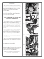
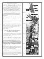
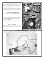
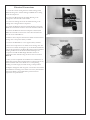
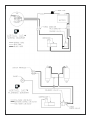
Installation Instructions
Compressor Kit
Harley Davidson Dyna Glide 91-07
ATTENTION
Statements in these instructions that are preceded by
the following words are of special significance:
W a r n i n g
This means there is the possibility of injury
to yourself or others.
Caution
This means there is the possibility of damage
to the motorcycle.
Note
Information of particular importance
has been placed in italics.
Important Notice
Note: Please read the following instructions completely
before starting installation!
Follow instructions in an authorized shop manual or take the
motorcycle to a competent dealer.
The motorcycle must be securely blocked to prevent it from
tipping over while work is being performed. Failure to do so
can cause serious damage and/or injury.
Progressive Suspension products are designed to be installed
and used on OEM (Original Equipment) frame and swingarm.
Installation and use of this product of other than OEM frame
and swingarm may produce an unsatisfactory ride and void the
warranty.
Warranty
Progressive Suspension Inc. warrants to the original purchaser
this Part to be free of manufacturing defects in materials and
workmanship for a period of one (1) year from the date of
purchase. In the event warranty service is required, you must
call Progressive Suspension immediately with a description of
the problem.
If it is deemed necessary for Progressive Suspension to make
an evaluation to determine whether the part is defective, a
return authorization number will be given by Progressive
Suspension. The parts must be packaged properly so as to not
cause further damage and returned prepaid to Progressive
Suspension with a copy of the original invoice of purchase and
a detailed letter outlining the nature of the problem. If after
the evaluation by Progressive Suspension the part was found to
be defective it will be repaired or replaced at no cost to you. If
we replace it, we may replace it with a reconditioned one of the
same design.
Progressive Suspension shall not be held liable for any
consequential or incidental damages resulting from the failure
of a Progressive Suspension part. Progressive Suspension shall
have no obligation if a part becomes defective as a result of
improper installation or abuse.
Warning
Lowering your motorcycle will decrease initial ground clearance.
The motorcycle will be lower to the ground and care should be
taken to avoid bottoming, especially over bumps or in turns.
Lowering a motorcycle can change the handling characteristics.
Always use extreme caution when riding after a change is made
and take time to get accustomed to any handling change.
5572 Fresca Drive, La Palma, CA 90623
Page 1/6
Note
The compressor, solenoid and T-fittings feature
high pressure quick disconnect fittings. To
connect the air lines, simply push them into the
fitting until they bottom out. They bottom out
about 3/16” past the first resistance you feel as
they go in. If you need to trim an air line it is VITAL
that you use a sharp razor blade and make a
square cut. DO NOT use Dykes or Wire Cutters,
these tools will cause the line to deform and leak.
If you need to disconnect an air line, simply push
the outer collar in and pull the air Line out of the
fitting. If you disconnect a line for any reason, we
recommend that you trim the line (approx. 1/8”)
prior to reinserting it in to the fitting to prevent any
leaks.
Note
This kit is designed specifically for use with our
AirTail IAS rear shocks. The shocks should be
installed prior to installing this kit. The use of this kit
replaces the need for the manual fill manifold
that comes standard with the shocks.
Tech line: 714.523.8700
Fax: 714.523.3220
[email protected]
Instruction Sheet Part # 3098-123 Rev A
Installation
1. Make sure that the AirTail IAS rear shocks are installed per
the installation instructions provided with the shocks. And that
you have connected the Bottoming Control air line (Black)
from each shock to a T-fitting under the seat and the Ride
Height Control air line (Blue) from each shock to a T-fitting
under the seat as instructed in the shock installation
instructions. Photo 1
2. Prepare your new compressor by installing it into the
appropriate mounting configuration. For Dyna Glide model
years 99-05 use steps 3 Through 7. For Dyna Glide model
years 91-98 use steps 3A Through 6A
Photo 1
STEPS 3 THROUGH 7 ARE FOR 1999 - 2005
DYNA GLIDE MODELS ONLY
3. Using the included 1/4-20 X 1 ½” Socket Head Cap Screws,
attach the Compressor, Mount and Bracket as shown in
Photo 2, be sure to match the orientation of the components
as shown in the photo. The Outlet Port should centered in, and
pushed through the open area shown as far as possible. Once
you have everything positioned properly, torque the two Cap
Screws to 6 ft/lbs. We recommend using blue loctite on these
two screws.
Photo 2
4. Using the included 1/4-20 X 3/4” Button Head Cap Screw,
1/4” Flat Washer and 1/4” Nylock Nut, install the Switch
manifold to the Bracket as shown. The Button Head Screw
must be installed as shown for adequate clearance when this
assembly in mounted to the Ignition Coil Mount. Photo 3
Photo 3
5. Following the procedures in your authorized shop manual,
remove the ignition coil.
6. Select the correct 1/4-20 Socket Head Cap Screws from the
included lengths. They will be approximately 1/4” longer than
stock.
1999-2003 Without Coil Cover: use 2” Screw
1999-2003 With Coil Cover: use 3 1/4” Screw
2004-2005 Without Coil Cover: use 2 ½”Screw
2004-2005 With Coil Cover: use 4” Screw
Photo 4
7. Install the Compressor / Switch assembly between the
Ignition Coil and Ignition Coil Mount using the selected Socket
Head Cap screws. We recommend putting a drop of blue loctite
on the screw threads and tightening them according to the
models authorized service manual. Photos 4 & 5
FOR 1999 - 2005 DYNA GLIDE MODELS,
CONTINUE WITH STEP #8
Photo 5
Page 2/6
Instruction Sheet Part # 3098-123 Rev A
Installation Continued
STEPS 3A THROUGH 6A ARE FOR 1991-1998
DYNA GLIDE MODELS ONLY
3A. Using the included 1/4-20 X 3/4” and 1/4-20 X 7/8”
Button Head Socket Screws, attach the Compressor, Mount
and Bracket as shown in Photo 2A, be sure to match the
orientation of the components as shown in the photo. The
Compressor Mount and Bushing should be pushed as far down
over the Compressor as possible. Once you have everything
positioned properly, torque the two Button Head Screws to 6
ft/lbs. We recommend using blue loctite on these two screws.
Refer to Photo 2A for proper location of the two different
length Screws.
Photo 2A
4A. Using the included 1/4-20 X 3/4” Button Head Cap Screw,
1/4” Flat Washer and 1/4” Nylock Nut, install the Switch
manifold to the Bracket as shown. Photo 3A
5A. Following the procedures in your authorizes shop manual,
remove the ignition coil.
Photo 3A
6A. Install the Compressor / Switch assembly between the
Ignition Coil and Ignition Coil bracket using the original Socket
Head Cap Screws We recommend putting a drop of blue loctite
on the screw threads and tightening them according to the
models authorized service manual.
Photos 4A & 5A
FOR 1991 - 2005 DYNA GLIDE MODELS,
CONTINUE WITH STEP #8
8. Run the Black, Red and 2 Orange wires from the Compressor
/Switch assembly straight up through the opening in the frame
into the open area under the seat.
9. Connect an 18” Black Air Line to the compressor outlet port.
Connect an 24” Black Air Line to the Top 45 degree air fitting
on the back of the Switch Manifold. Connect an 24” Blue Air
Line to the Bottom 45 degree air fitting on the back of the
Switch Manifold. Photos 5 & 5A Run all three Air Lines into
the area under the seat. To insure sufficient line lengths and
clearances for all lines and fittings, it is recommended that
you wait until the entire system has been connected before
trimming these airlines and making the final connections
to the “T” fittings that run to the shocks.
Photo 4A
Photo 5A
10. Place the solenoid valve in the vacant space under the seat.
You may need to re-arrange the wire loom bundles to place the
valve where shown on some models. Photo 6
11. Install short Air Lines into the two check valves coming out
of the Solenoid. Black Air Line to the Large Check Valve and
Blue Air Line to the Small Check Valve. Attach T- Fittings to the
ends of each of these short Air Lines. Insert the Black Air Line
from the Compressor Output Port into one side of the T-Fitting
that is attached to the Solenoid Valve. Photos 6 & 7
Page 3/6
Photo 6
Instruction Sheet Part # 3098-123 Rev A
Installation Continued
12. Connect the Black Air Line coming from the Switch Housing
into the new T-Fitting (Black Air Line) you installed in step 11.
Do the same with the Blue Air Line. Be sure to match the Air
Line Color when you connect the lines.
13. Using matching color Air Lines, connect the open end of the
new T-Fittings, from step 11, to the T-fittings that were installed
with the shocks. Again, be sure to match Air Line Colors.
Pressure Gauge Installation
1. On the right side of the bike, remove the two rear rocker box
bolts from the rear cylinder. It may be necessary to loosen and
raise or remove the fuel tank for clearance to remove the bolts.
2. Mount the air pressure gauge assembly to the rocker box with
the two bolts removed in step 1. Tighten these bolts according to
your models shop manual. Reinstall and tighten fuel tank if
removed in step 1. Photo 8
Photo 7
3. Route the pressure gauge airline into the area under the seat and
connect it into the open end of the T-Fitting attached to the
solenoid valve. Photo 7
Note
The air pressure gauge will normally leak back down to 0 psi after using the
compressor. This does not leak any air from the shocks and has no effect on
the performance of the system.
Photo 8
Electrical Connections
The next few steps will take you through the wiring of the system. Refer to Photo 9 below and the wiring diagram for
clarification. The final connection to the battery positive and installation of the fuse should be the final two steps.
Photo 9
Page 4/6
Instruction Sheet Part # 3098-123 Rev A
Electrical Connections
1. Locate the 3 wires coming from the switch housing, a Red,
Black & Orange wire. And the Orange and Black wires coming
from the Compressor
2. Connect the Red wire from the Switch Housing to the
Orange wire with the built in Fuse holder.
3. Connect the Orange wire from the Switch Housing to the
Orange wire coming from the Compressor.
4. Connect the Black wire from the Switch Housing to the Thin
Black wire with female connector that comes from the Solenoid.
5. Connect the Black wire from the Compressor and the Thin
Black wire with male connector that comes from the Solenoid
into the 2 into 1 Black Wire Y .
Photo 10
6. Remove the 15 amp fuse from the fuse holder and connect this
Orange wire to the positive battery terminal.
7. Connect the Black Wire Y to the negative battery terminal.
8. Insert the 15 amp fuse into it’s holder on the Orange wire. The
system is now “HOT”. Pressing the top of the Rocker Switch will
energize the Compressor and fill the Bottoming Control Chamber.
Pressing the Bottom of the Rocker Switch will energize the
Compressor and fill the Ride Height Chamber. Pressure is
released from each chamber using the release valve as shown in
Photo 11
9. Once you have completed the installation and verified that it is
functioning properly, We recommend that you trim and secure any
airlines and wires that need it. Make sure to avoid pinching,
bending at extreme angles, heat and moving or sharp surfaces.
Photo 11
10. Replace and tighten down any parts or accessories removed for
this installation according to the vehicle or accessory manufactures
instructions. Refer to the included Set Up instructions for
suspension set up information.
Page 5/6
Instruction Sheet Part # 3098-123 Rev A
Page 6/6
Instruction Sheet Part # 3098-123 Rev A