1
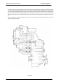
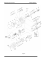
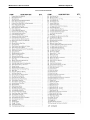
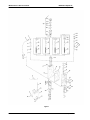
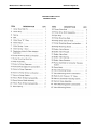
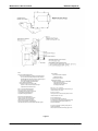
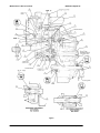
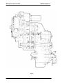
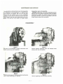
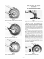
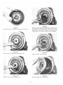
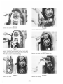
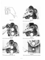
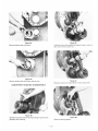
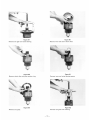
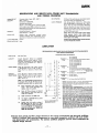
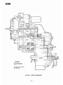
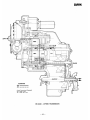
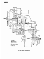
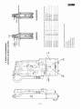
Service Manual
Powershift Transmission
24000 Series HR 4-Speed Long Drop
TSM-0009
April 2000
Maintenance & Service manual
HR24000 4 Speed LD
FOREWORD
This manual has been prepared to provide the customer and the maintenance personnel
with information and instructions on the maintenance and repair of the Spicer OffHighway Power Shift Transmission.
Extreme care has been exercised in the design" selection of materials and manufacturing
of these units. The slight outlay in personal attention and cost required to provide regular
and proper lubrication, inspection at stated intervals, and such adjustments as may be
indicated will be reimbursed many times in low cost operation and trouble free service.
In order to become familiar with the various parts of the transmission, its principal of
operation, trouble shooting and adjustments, it is urged that the mechanic study the
instructions in this manual carefully and use it as a reference when performing
maintenance and repair operations.
Whenever repair or replacement of component parts is required" only Spicer Off-Highway
approved parts as listed in the applicable parts manual should be used. Use of "will-fit" or
non-approved parts may endanger proper operation and performance of the equipment.
Spicer Off-Highway does not warrant repair or replacement parts, nor failures resulting
from the use thereof, which are not supplied by or approved Spicer Off-Highway.
IMPORTANT: Always furnish the Distributor with the transmission serial and
model number when ordering parts.
TOWING OR PUSH STARTING
Before towing the vehicle, be sure to lift the rear wheels off the ground or
disconnect the driveline to avoid damage to the transmission during towing.
NOTE : If the transmission has 4 wheel drive, disconnect both front and rear
drivelines. Because of the design of the hydraulic system, the engine cannot be
started by pushing or towing
©Copyright Dana Spicer Off-Highway Products Division
Unpublished Material – All rights reserved
Limited Distribution
No part of this work may be reproduced in any form
Under any means without direct written permission of
Dana Spicer Off-Highway Products Division
Date: Apr 2000
Maintenance & Service manual
HR24000 4 Speed LD
TABLE OF CONTENTS
Date: Apr 2000
Maintenance & Service manual
HR24000 4 Speed LD
HOW THE UNITS OPERATE
The transmission and hydraulic torque portion of the power train enacts an important role in transmitting engine power to the driving
wheels. In order to properly maintain and service these units it is important to first understand their function and how they operate.
The transmission and torque converter function together and operate through a common hydraulic system. It is necessary to consider
both units in the study of their function and operation.
To supplement the text below, and for reference use therewith, the following illustrations are provided:
The R, HR, and MHR Model Transmissions are of three basic designs.
The R Model consists of a separate torque converter" mounted to the engine with the powershlft transmission remotely mounted and
connected to the torque converter with a drive shaft,
The HR Model consists of a torque converter and powershifted transmission in one package mounted directly to the engine.
The MHR version is a mid-mount torque converter and transmission assembly connected to the engine by means of a drive shaft,
(See Fig, A for basic design silhouette.)
The shift control valve assembly may be mounted directly on the side of the converter housing or front transmission cover, or remote
mounted and connected to the transmission by means of flexible hoses. The function of the control valve assembly is to direct oil
under pressure to the desired directional and speed clutch. A provision is made on certain models to neutralize the transmission when
the brakes are applied. This is accomplished through use of a brake actuated shutoff valve. The speed and direction clutch assemblies are mounted inside the transmission case and are connected to the output shaft of the converter either by direct gearing or drive
shaft. The purpose of the speed or directional clutches is to direct the power flow through the gear train to provide the desired speed
range and direction.
An axle disconnect is optional and is located on the output shaft, The drive to the front or rear axle can be disconnected or connected
by manual shifting.
Date: Apr 2000
Maintenance & Service manual
HR24000 4 Speed LD
With the engine running, the converter charging pump draws oil from the transmission sump through the removable oil suction screen
and directs it through the oil filter and the pressure regulating valve.
The pressure regulating valve maintains pressure to the transmission control cover for actuating the direc tion and speed clutches,
This requires a small portion of the total volume of oil used in the system. The remaining volume of oil is directed through the torque
converter circuit to the oil cooler and returns to the transmission for positive lubrication, This regulator valve consists of a hardened
valve spool operating in a closely fitted bore. The valve spool is spring loaded to hold the valve in a closed position. When a specific
pressure is achieved, the valve spool works against the spring until a port is exposed along the side of the bore, This sequence of
events provides the proper system pressure.
After entering the converter housing the oil is directed through the stator support to the converter blade cavity and exits in the
passage between the turbine shaft and converter support, The oil then flows out of the converter to the oil cooler. After leaving the
cooler, the oil is directed to a lubricating fitting on the transmission and through a series of tubes and passages lubricates the
transmission bearings and clutches. The oil then gravity drains to the transmission sump.
The hydraulic torque converter consists basically of three elements and their related parts to multiply engine torque, The engine
power is transmitted from the engine flywheel to the impeller element through the impeller cover. This element is the pump portion of
the hydraulic torque converter and is the primary component which starts the oil flowing to the other components which results in
torque multiplication. This element can be compared to a centrifugal pump in that it picks up fluid at its center and discharges at its
outer diameter.
The torque converter turbine is mounted opposite the impeller and is connected to the output shaft of the torque converter. This
element receives fluid at its outer diameter and discharges at its center. Fluid directed by the impeller out into the particular design of
blading in the turbine and reaction member is the means by which the hydraulic torque converter multiplies torque.
The reaction member of the torque converter is located between and at the center or inner diameters of the impeller and turbine
elements, Its function is to take the fluid which is exhausting from the inner portion of the turbine and change its direction to allow
correct entry for recirculation into the impeller element.
The torque converter will multiply engine torque to its designed maximum multiplication ratio when the output shaft is at zero RPM,
Therefore, we can say that as the output shaft is decreasing in speed the torque multiplication is increasing.
The shift control valve assembly consists of a valve body with selector valve spools. A detent ball and spring in the selector spool
provides one position for each speed range. A detent ball and spring in the direction spool provides three positions, one each for
forward, neutral and reverse.
With the engine running and the directional control lever in neutral position, oil pressure from the regulating valve is blocked at the
control valve, and the transmission is in neutral. Movement of the forward and reverse spool will direct oil, under pressure to either
the forward or reverse direction clutch as desired, When either directional clutch is selected the opposite clutch is relieved of pressure
and vents back through the direction selector spool. The same procedure is used in the speed selector.
The direction or speed clutch assembly consists of a drum with internal splines and a bore to receive a hy draulically actuated piston,
The piston is "oil tight" by the use of sealing rings. A steel disc with external splines is inserted into the drum and rests against the
piston. Next a friction disc with splines at the inner diameter is inserted. Discs are alternated until the required total is achieved. A
heavy back-up plate is then inserted and secured with a snap ring, A Hub with O.D. splines is inserted into the splines of discs with
teeth on the inner diameter. The discs and hub are free to increase in speed or rotate in the opposite direc tion as long as no pressure
is present in that specific clutch.
Date: Apr 2000
Maintenance & Service manual
HR24000 4 Speed LD
To engage the clutch, as previously stated, the control valve is placed in the desired position. This allows oil under pressure to flow
from the control valve, through a passageway, to a chosen clutch shaft. This shaft has a drilled passageway for oil under pressure to
enter the shaft. Oil pressure sealing rings are located on the clutch shaft, These rings direct oil under pressure to a desired clutch.
Pressure of the oil forces the piston and discs against the heavy back-up plate, The discs, with teeth on the outer diameter, clamping
against discs with teeth on the inner diameter, enables the hub and clutch shaft to be locked together and allows them to drive as a
unit.
There are bleed balls or bleed orifices, depending upon the model, in the clutch piston which allow quick escape for oil when the
pressure to the piston is released.
FIGURE A
Date: Apr 2000
Maintenance & Service manual
HR24000 4 Speed LD
Figure B
Date: Apr 2000
Maintenance & Service manual
HR24000 4 Speed LD
CONVERTER AND TRANSMISSION
CASE GROUP
Date: Apr 2000
Maintenance & Service manual
HR24000 4 Speed LD
Figure C
Date: Apr 2000
Maintenance & Service manual
HR24000 4 Speed LD
CONVERTER & PUMP DRIVE GROUP
Date: Apr 2000
Maintenance & Service manual
HR24000 4 Speed LD
Figure D
Date: Apr 2000
Maintenance & Service manual
HR24000 4 Speed LD
CLUTCH AND GEAR GROUP
Date: Apr 2000
Maintenance & Service manual
HR24000 4 Speed LD
Figure E
Date: Apr 2000
Maintenance & Service manual
HR24000 4 Speed LD
CLUTCH ASSEMBLY-1ST
CLUTCH ASSEMBLY -FORWARD
CLUTCH ASSEMBLY 4TH & 3RD
CLUTCH ASSIEMBLY -REVERSE -2ND
Date: Apr 2000
Maintenance & Service manual
HR24000 4 Speed LD
Figure F
Date: Apr 2000
Maintenance & Service manual
HR24000 4 Speed LD
CONTROL VALVE ASSEMBLY
Date: Apr 2000
Maintenance & Service manual
HR24000 4 Speed LD
FIGURE G
Date: Apr 2000
Maintenance & Service manual
HR24000 4 Speed LD
CHARGING PUMP & VALVE
ASSEMBLY GROUP
Date: Apr 2000
Maintenance & Service manual
HR24000 4 Speed LD
Figure H
Date: Apr 2000
Maintenance & Service manual
HR24000 4 Speed LD
Notes
Hose Line Operating Requirements :
1 Pressure Lines-Suitable for operation from ambient to 250°F
[121°C] continuous operating temperature Must withstand
300 PSI [2068 kPa] continuous pressure, with 600 PSI [4137
kPa] intermittent surges Ref SA.E. Spec. No
J517, 100R1 Hydraulic Hose Specifications
2 See Lubrication Specifications.
3 All hose lines used must conform to SAE
Spec No J 1019 Tests and Procedures for High
Temperature Transmission Oil Hose.
Test Conditions
1 Converter Outlet Oil Temperature
180-220°F [82-104°C]
2 Transmission in Neutral.
Operating Specifications
1 25 PSI [173 kPa] Min pressure at 2000 RPM
engine speed and a max of
70 PSI [483 kPa] outlet pressure at
a no-load governed speed
Ports "A" , "F". "K", "L. and "M"
These ports can be used for field "Trouble Shooting" or
vehicle "Production Line.. tests
Port "L” Converter Outlet Temperature
Port is to be used for Converter Outlet
Temperature pick-up. Gauge is to be located
in the Operator Compartment See Oil
Temperature Gauge Specifications
Ports "F"' "L" and "M'.
These ports are to be used as check points for normal
vehicle "Production Line.. test
Port "M"-Converter Outlet Pressure.
Pressure must be measured during normal
vehicle "Production Line" test Converter
outlet pressure equals the total pressure
drop of the Heat Exchanger, Heat Exchanger
Lines and back pressure of the transmission lubrication system.
Port "F"-Clutch Pressure
It is recommended that clutch pressure
be monitored by a gauge having an indicator dial range
of 0 to 400 PSI [0 to 2758 kPa] and located in the
Operator Compartment
Ports "G" and "H"-Back-up Warning These ports are
provided for installation
of Back-up Pressure Switch for Warning Light or Horn
Figure H
Date: Apr 2000
Maintenance & Service manual
HR24000 4 Speed LD
Figure I
Date: Apr 2000
Maintenance & Service manual
HR24000 4 Speed LD
Figure I
Date: Apr 2000
Maintenance & Service manual
HR24000 4 Speed LD
Figure J
Date: Apr 2000
Copyright 2010 Dana Holding Corporation
All content is subject to copyright by Dana and may not
be reproduced in whole or in part by any means,
electronic or otherwise, without prior written approval.
THIS INFORMATION IS NOT INTENDED FOR SALE OR
RESALE, AND THIS NOTICE MUST REMAIN ON ALL
COPIES.
For product inquiries or support,
visit www.dana.com or call 419-887-6445
For other service publications,
visit www.SpicerParts.com/literature.asp
For online service parts ordering,
visit www.SpicerParts.com/order.asp