1
DCS800
Selection, Installation and Start-Up Manual for Rebuild Kits
DCS800 Drives
DCS800 Single Drive Manuals
All the documents available for the drive system DCS800 are listed below:
Public. number
3ADW000191
3ADW000211
E
x
x
D
p
Language
I
ES
p
p
F
p
CN
3ADW000190
3ADW000192
3ADW000194
3ADW000193
3ADW000032
3ADW000163
3ADW000195
3ADW000196
3ADW000136
3ADW000153
x
x
x
x
x
x
x
p
p
p
x
x
x
p
p
x
p
p
p
p
p
p
p
x
p
p
3BFE64560981
3BFE00073846
3AFE63988235
3BFE64285513
x
x
x
x
CoDeSys_V23
3ADW000199
3ADW000058
x
x
DCS800-E Panel Solution
Flyer DCS800-E Panel solution
Hardware Manual DCS800-E
3ADW000210
3ADW000224
x
x
DCS800-A Enclosed Converters
Flyer DCS800-A
System description DCS800-A
Installation of DCS800-A
3ADW000213
3ADW000198
3ADW000091
x
p
p
3ADW000007
3ADW000197
p
p
Extension Modules
RAIO-01 Analogue IO Extension
RDIO-01 Digital IO Extension
AIMA R-slot extension
3AFE64484567
3AFE64485733
3AFE64661442
x
x
x
Serial Communication
Drive specific serial communication
NETA Remote diagnostic interface
3AFE64605062
x
3AFE64504215
x
Fieldbus Adapter with DC Drives RCNA-01 (ControlNet)
3AFE64506005
x
Fieldbus Adapter with DC Drives RDNA- (DeviceNet)
3AFE64504223
x
Fieldbus Adapter with DC Drives RMBA (MODBUS)
3AFE64498851
x
3AFE64539736
x
DCS800 Quick Guide
DCS800 Tools & Documentation CD
DCS800 Converter module
Flyer DCS800
Technical Catalogue DCS800
Hardware Manual DCS800
Firmware Manual DCS800
Installation according to EMC
Technical Guide
Service Manual DCS800
Planning and Start-up for12-Pulse converters
CMA-2 Board
Flyer Hard - Parallel
Drive Tools
DriveWindow 2.x - User's Manual
DriveOPC 2.x - User's Manual
Optical DDCS Communication Link
DDCS Branching Units - User´s Manual
DCS800 Applications
PLC Programming with CoDeSys
61131 DCS800 target +tool description - Application Program
Winding with the DCS 800XXXXX
Winder application description
Flyer magnetic application
Magnetic application description
DCS800-R Rebuild System
Flyer DCS800-R
DCS800-R Manual
DCS500/DCS600 upgrade manual
Fieldbus Adapter with DC Drives RPBA- (PROFIBUS)
Fieldbus Adapter with DC Drives RCAN-02 (CANopen)
Fieldbus Adapter with DC Drives RETA (Ethernet)
x -> existing
p -> planned
Status 01.2007
DCS800 Drive Manuals-List_c.doc
x
x
p
p
p
x
p
p
p
x
DCS800 Drives
DCS800-R0x
Selection, Installation and
Start-Up Manual for Rebuild Kits
Code:
3ADW000195R0101 Rev A
DCS800 Service Manual e a.DOC
EFFECTIVE:
SUPERSEDES:
June 19th, 2006
3ADW000197R0101
DCS800-R
Sel e
ea
a
3ADW000195R0101
DCS800 Service
Manual
3
Table of contents
Introduction
How to use this manual .................................................................................................. 5
Contents of this manual.................................................................................................. 5
Associated publications .................................................................................................. 5
0H
1H
2H
Basic Selection
Technical preconditions and limits ................................................................................. 7
Selecting the suitable Rebuild kit ................................................................................... 7
Hardware conditions .................................................................................................... 8
Drive´s design conditions ............................................................................................. 9
Conditions caused by the application........................................................................... 9
Type coding and accessories..................................................................................... 10
3H
4H
5H
6H
7H
8H
Hardware
Basic components of the DCS800-R kit ....................................................................... 13
Housing for main electronics ........................................................................................ 13
Pre-assembled part ...................................................................................................... 14
Loose parts................................................................................................................... 14
Optional parts ............................................................................................................... 15
Dimensions main electronic housing ............................................................................ 16
Environmental conditions ............................................................................................. 17
Pulse transformer board SDCS-PIN-48........................................................................ 19
Wiring ......................................................................................................................... 19
Measurement board SDCS-PIN-51 .............................................................................. 20
Wiring ......................................................................................................................... 22
Fastening ................................................................................................................... 22
PTC temperature sensor............................................................................................ 22
HW type coding.......................................................................................................... 22
Voltage coding ........................................................................................................... 23
Nominal current coding .............................................................................................. 23
Additional settings ...................................................................................................... 25
Interface board SDCS-REB-1....................................................................................... 26
Power supply.............................................................................................................. 27
Functionality ............................................................................................................... 28
Fastening ................................................................................................................... 28
Diagram...................................................................................................................... 29
Interface board SDCS-REB-3....................................................................................... 30
Firing pulses............................................................................................................... 30
Signal flow and Thyristor designation ........................................................................ 30
Design hints ............................................................................................................... 32
Signal handling........................................................................................................... 32
Plug connectors X1113: and X2113:.......................................................................... 33
9H
10H
11H
12H
13H
14H
15H
16H
17H
18H
19H
20H
21H
22H
23H
24H
25H
26H
27H
28H
29H
30H
31H
32H
33H
34H
35H
36H
Interfacing the Electronics and Thyristors
Connection for 2-quadrant application – No parallel Thyristors ................................. 35
Connection for 4-quadrant application – No parallel Thyristors ................................. 36
37H
38H
Table of contents
3ADW000xxxR0101 DCS800-R Sel e a
4
Connection for 4-quadrant application - parallel thyristors ......................................... 37
Connection for 2-quadrant application - parallel thyristors ......................................... 38
39H
40H
Installation
Background for the figures of this chapter ................................................................. 39
Hints for Cabling......................................................................................................... 51
41H
42H
Safety Instructions
What this chapter contains ........................................................................................... 53
To which products this chapter applies ........................................................................ 53
Use of warnings and notes ........................................................................................... 53
Installation and maintenance work ............................................................................... 54
Grounding................................................................................................................... 55
Mechanical installation ................................................................................................. 56
Operation...................................................................................................................... 56
43H
44H
45H
46H
47H
48H
49H
Start-up
What this chapter contains ........................................................................................... 59
Safety Instructions...................................................................................................... 59
Points to be observed because of the situation ......................................................... 59
Maintenance work ...................................................................................................... 60
Tools .......................................................................................................................... 60
Measurements with the “old” equipment still working................................................. 60
Mounting the Kit ......................................................................................................... 61
Wiring the Kit .............................................................................................................. 61
Commissioning the Kit................................................................................................ 62
50H
51H
52H
53H
54H
55H
56H
57H
58H
Table of contents
3ADW000195R0101 DCS800 Service Manual e a
5
Introduction
How to use this manual
The purpose of this manual is to provide you with the information
necessary to select the right rebuild kit with all the necessary or
available options, to install it, do the start-up and operate it as a DC
drive system. Depending on the kit's configuration, different functionality and different options concerning the user interface are
available. As long as the hardware needs to be named or crossreferenced to in a very general way, the term Rebuild kit will be
used.
Contents of this manual
Introduction describes how to use this manual and the boundary
conditions applying.
Basic Selection provides the information about the types of the
Rebuild kits, their type designations and options.
Hardware description provides the information about the boards
and components
Interfacing the Electronics and Thyristors provides the information about the configurations and functions of drives and examples
of the whole circuit diagram.
Installation provides the information about required ambient conditions, space requirements, cabling and wiring and how to install a
rebuild system.
Start-up gives some general guidelines and cross references how
to commission and start up a DC drive system using a Rebuild kit.
Associated publications
Associated publications see inner page of the jacket of that manual.
Introduction
3ADW000xxxR0101 DCS800-R Sel e a
6
Introduction
3ADW000197R0101 DCS800-R Sel e a
7
Basic Selection
Technical preconditions and limits
If an electrical drive is in operation for several years, most often discussions will be
started about items like:
- better factory automation based on latest technology
- decrease of standstill time of production
- availability of spare parts
- increase of productivity; perhaps an enlargement of the whole installation using
both types of drives, DC and AC drives
- and other arguments
These wishes can be turned into real life by:
- upgrading the drive itself completely
- upgrading only the converter, which had controlled the DC motor
- upgrading the converter´s electronics only
- upgrading a part of the converter´s electronics.
For a final solution, all the benefits described by:
• higher production
• more accurate control
• design of state of the art
• others
will be compared with the disadvantages of revamping described by:
• standstill time of production • hardware cost • training etc.
If this comparison is based on an upgrade of the converter´s electronics the Rebuild kit, which is described within this document, may be a solution. Before the final decision is made to use a Rebuild kit, the configuration of the existing drive
needs to be checked more in detail to make sure the kit fulfills all demands.
Selecting the suitable Rebuild kit
The basic structure of a converter to control a DC motor looks like this:
Converter control electronics
with interface to:
- thyristor bridge
- PLC
thyristor
bridge
The electronics of the existing converter indicated by the left box above is splitted
into 2 boxes in the kit.
electronics:
interface to
PLC
electronics:
interface to
thyristor
bridge
Rebuild kit
thyristor
bridge
Existing
The Rebuild kit can be used for armature bridges in non-regenerative or regenera-
Basic Selection
3ADW000197R0101 DCS800-R Sel e a
8
tive mode with maximum 4 thyristors in parallel. In case there are more than 4 thyristors in parallel per current direction there is no standard kit prepared; please contact your local ABB organization.
To selecting the Rebuild kit, first the HARDWARE CONDITIONS must be checked
to become aware of critical limitations. If this is not a problem the DRIVE´S
DESIGN CONDITIONS will give some guidelines for the overall design. After that a
decision must be made for the functionality of the interface between the kit and the
Programmable Logic Controller. Depending on that, the Rebuild kit´s type code
can be fixed by using the type designations listed on the next pages. Afterwards
please check if all conditions are fulfilled as listed in CONDITIONS CAUSED BY
THE APPLICATION.
Hardware conditions
If a Rebuild kit is taken into consideration, the items listed afterwards will give
some help to decide whether a Rebuild kit or a converter module / enclosed converter is the better solution.
- Before an existing DC power part is upgraded by the Rebuild kit, it should be
checked if a brand new module may be easier to install or may be a more reliable solution (tested power stack).
- The existing power bridge should be build up by max. 4 thyristors in parallel per
current direction (solution for more thyristors in parallel on request). It doesn't
matter whether the bridges have the same number of thyristors in parallel.
- The supply voltage used for the existing thyristor bridge has to be lower than
990 V because of the devices used to interface the electronics to the thyristors
(higher mains voltages on request).
- The thyristors actually used should be of a disk type. One single thyristor
bridge should be capable of running around 1000 A or more, if the converter is
built up by more than one bridge in parallel. If a single bridge cannot give this
current a brand new converter is probably the more economical solution.
- The ratio between reverse / forward blocking voltage of the thyristors and the
nominal line voltage should be factor 3 or higher the blocking voltage has to be
measured on a thyristor test stand if the actual blocking voltage gives a lower
ratio the thyristor(s) need to be replaced. In such a case, please check if a
complete new converter may be more economical.
Basic Selection
3ADW000197R0101 DCS800-R Sel e a
9
Drive´s design conditions
It is intended to install the kit into the existing drive cabinet. The following drive equipment will be reused and should therefore be in good condition:
- Check all parts in the AC supply like main disconnecting switch with fuses or main
contactor or similar for good condition.
- Check the thyristor bridge itself (fixing devices, press clamps for thyristor mounting,
etc.) with cooling equipment for good condition.
- If a Rebuild kit is used for the armature supply the existing field supply can be reused or upgraded too.
- If the field supply will be upgraded one of these can be used:
SDCS-FEX-425-internal
(built in; 1 or 3 phase)
DCF803-0035
(external; 1 or 3 phase)
DCF803-0050 / ...4-0050
(external; 1 phase)
DCS800-S0x-xxxx-05
(external; 3 phase)
- If the old field supply will be reused check the overall strategy concerning
monitoring, fault tracing and overall control and performance of the drive. Either a binary or an analogue signal should be available indicating “field supply
equipment o.k.”. In case this signal is not available galvanic isolated then it
should be made potentially free for safety reasons. If the drive should also be
used in the field weakening range, an analogue signal, representing the actual
field current, is highly recommended. It will be used for monitoring and fault indications generated within the Rebuild kit´s software.
- Depending on the old control structure an analogue tacho generator can be reused. A pulse generator can only be (re)used if it generates a pulse train as an
output signal (see Hardware Manual).
- The Rebuild kit expects an armature current feedback signal for the current control
loop. This signal normally is taken from two current transformers on the a.c. side of
the thyristor bridge. The current transformers shall give 0.5 - 0.85 A, which corresponds to the nominal current of the thyristor bridge (other solutions on request).
- A 115V or 230 V AC supply for the Rebuild kit´s electronics is needed.
Conditions caused by the application
It has to be checked if the selected Rebuild kit type can handle the application of the
existing drive. As long as the existing one was used in a 6 pulse bridge configuration,
there is no limitation.
- If the existing bridge has been used in a configuration different to 6-pulse , additional engineering is needed. It should be checked at first, if a standard converter
DCS800-S0x can be used for such a configuration. Most likely the DCS800-R0x
can be designed similar as with a standard converter.
- There are drives used in the past in a configuration sometimes named MASTER FOLLOWER or MASTER - SLAVE or similar. In all these applications, one drive
had generated references or commands for the second, third etc. The Rebuild kit is
basically prepared for those configurations; the final wiring may be different. For
more details, please refer to the documentation.
- If the existing converter has been used in a non motor application most often a prepared solution is not available, but most often an engineered solution can be found.
Please contact your local ABB engineering organization.
Basic Selection
3ADW000197R0101 DCS800-R Sel e a
10
Type coding and accessories
There is only one mechanical construction for all the different versions of the kit. It
basically serves as a cover for that part named DCS800-R0x on the next figure.
Ordering of the kit is done with the ordering code shown on the right page. The options available for the Rebuild kit are identical as for a DCS800-S0x converter.
Some options (e.g. +K454 adapter module for PROFIBUS DP communication) will
be build in if ordered, some will come within the kits box and others need to be
specified seperate and will come in a separate box.
All applications, which can be done with a DCS800 converter, can be done with
this DCR kit too, as long as the components, necessary for that application can be
used for both systems. Engineering help is given within the DCS800 converter
module´s documentation (see inner page of the jacket of this manual). This manual
just focuses on items related to the engineering of the Rebuild kit.
DriveWindow
Door
mounting
kit
-NDPA-02
(PCMCIA)
-NDPC-12
-NISA-03 (ISA)
Panel
CDP 312
PC +
≤500V
Overriding
control
F2
T2
115/230 V
RJ45
a or b
NDBU95
DCS800-R00-0000-00
optical fibre
DCS800 CP
COM-8
RDIO
RAIO
Ch1
Slot1
Slot3
Ch0
optical fibre
AIMA
Slot2
SDCS-CCB4
Ch2
Slot 2
Slot 4
Slot 3
Memory Card
X19
Ch3
X2
24V-
X1
DSL
X51X52
X34
X3
X4
X5
X6
DSL
X53
X7
NDBU95
DCSLink
3
1
3
8
twisted pair
7
Advant
controller
IOB-2x
PC +
CoDeSys
DWL
8
RS232
Figure 1: Overview of DCS800-R System
Basic Selection
3ADW000197R0101 DCS800-R Sel e a
8
IOB-3
3
4
FEX-425 Internal
CON-4
Master/
Follower
POW
1
POW-4
Slot 1
Fieldbus
adapter Rxxx
or RDIO/RAIO
11
Ordering code:
DCS800 - R0 1 - 0000 - 01 + 0000
DC Drives
Product family
DCS800 converter
Rebuild kit
Bridge type
1 = single (2Q)
2 = anti (4Q)
Number of parallel / antiparallel thyristors
01 = 1 bridge
02 = 2 bridges in parallel
03 = 3 bridges in parallel
04 = 4 bridges in parallel
Options
+xxxx codes according
list for add-on options
selectable option
≤990V
Existing parts
Residual current detection
a
b
a or b
b
~
a
~
-
QUINT-PS
-
REB-1
REB-2
M
REB-3
PIN-48
existing field exciter
DCS800-S0x as field exciter
DCF 803-0050 / 804-0050
DCF 803-0035
PIN-48
PIN
1x
PIN-51
M
to motor field
T
T
DCS8-R_sys_ovw.dsf
Overview of DCS800-R System
Basic Selection
3ADW000197R0101 DCS800-R Sel e a
12
Basic Selection
3ADW000197R0101 DCS800-R Sel e a
13
Hardware
This chapter gives information about all the components and boards being exclusively used at the DCS800-R0x kit. Components which are used at DCS800-S0x
converter modules are just mentioned within that chapter, but not described in detail. In case those components need special handling it will be listed here. This for
example is valid for measuring actual signals at the existing power stack or doing
the galvanic isolation for the firing pulse transmission.
In addition to that environmental conditions, dimensions and some hints are listed
for better and straighter forward engineering.
All other components which may come or may had been ordered together with the
kit are described in detail either within the DCS800 Hardware Manual or within
their dedicated documentation.
Basic components of the DCS800-R kit
The kit is ordered according to the type designation at chapter Basic Selection.
The delivery can be subdivided into several parts, mostly two:
- rebuild kit´s main electronics already pre-assembled
- electronic boards and cables to measure signals at the power part and control
the existing thyristors; this will come as loose parts
The interface towards the PLC can be done via inputs / outputs. In this case optional parts may be added.
Housing for main electronics
DCS800-R0x kit´s main electronics, named DCS800-R00-0000-00
Hardware
3ADW000197R0101 DCS800-R Sel e a
14
Pre-assembled part
This part is pre-assembled and consists of:
- Housing for electronics (as shown on figure before)
- Control board SDCS-CON-4 built-in
- Electronic power supply SDCS-POW-4 built in (including flat cable to SDCSCON-4). This board needs to be feed by a 2-phase AC line voltage, either 115
V or 230 V
- Drive-to-drive interfacevia SDCS-DSL-4 board
- Control panel DCS800 CP
- Flat cable interconnection board SDCS-CCB4
Hint: The older version of the electronic power supply SDCS-POW-1 can be used
as a spare part for the actual one, SDCS-POW-4.
As shown at the end of chapter Basic Selection some options can be ordered using a so called plus code. Such options most often can only be used together with
the controller board; sometimes they need to be plugged on the controller board to
get their function. Those options will be put at their correct place during production
and therefore will come within the housing.
Plug-in modules (e.g. Prfibus, I/O extensions) and the field supply FEX-425 Internal are parts handled by plus codes.
Loose parts
The kit is available as a 2-Q or 4-Q version. Both of them are available for power
parts with one up to four thyristors in parallel. Because of the different versions
some components will be part of the delivery in every case like the SDCS-PIN-51
and SDCS-REB-1 board, others depend on the configuration:
DCS800-R01
(2-Q)
DCS800-R02
(4-Q)
-0000-01
(1 bridge)
1x PIN-48
-------
-0000-01
(1 bridge)
2x PIN-48
-------
-0000-02
(2 bridges)
2x PIN-48
2x QUINT-PS
1x REB-2
-0000-02
(2 bridges)
4x PIN-48
2x QUINT-PS
1x REB-2
Hardware
3ADW000197R0101 DCS800-R Sel e a
-0000-03
(3 bridges)
3x PIN-48
2x QUINT-PS
1x REB-2
-0000-03
(3 bridges)
6x PIN-48
2x QUINT-PS
1x REB-2
-0000-04
(4 bridges)
4x PIN-48
2x QUINT-PS
1x REB-2
-0000-04
(4 bridges)
8x PIN-48
2x QUINT-PS
1x REB-2
15
The boards serve for different purposes:
- SDCS-PIN-48:
Pulse transformer board is mounted on a card holder. For the interconnections
6 firing leads (twisted pair; system plug on one end) and a shielded flat cable
(round; 20-pole) will come with the kit. For cable length, please refer to chapter
Installation.
- SDCS-PIN-51:
Measuring board is mounted on a card holder. For the interconnections 5 leads
for the AC and DC voltage measurement (single core; 6,3 mm faston on one
end), 2 leads for the current measurement (twisted pair; system plug on one
end), 2 shielded flat cable (round; 16 pole) and a pluggable resistor for X22 will
come with the kit. For cable length, please refer to chapter Installation.
- SDCS-REB-1:
(Interface board)
- QUINT-PS:
(Power supply)
- SDCS-REB-2:
Pulse amplification board for more than one bridge in parallel is mounted on a
card holder. For the interconnections 2 flat cables (20-pole) will come with the
kit. For cable length, please refer to chapter Installation.
Optional parts
The options available differ in their usage. Some of them are related to the rebuild
kit, some to the drive itself or to the application the drive is used for:
- Subassembly SDCS-REB-3:
This board is used together with the SDCS-REB-2 and SDCS-PIN-48. With the
help of this board the firing pulse assignment can be changed and adapted to
the needs given by the existing power part construction. The board will come
mounted on a card holder. For the interconnections 4 flat cables (20-pole) will
come with the kit. For cable length, please refer to chapter Installation.
- Plus code +S164
(FEX-425 Internal):
This field supply can be build into the electronic housing. When ordered using
the plus code it will be mounted inside the housing during production. The board
can be connected to any 2- or 3-phase power supply with up to 500V.
Power rating:
with 2-phase supply:
16A max !
with 3-phase supply:
25A max !
When doing the engineering please make sure all conditions for the power supply configuration are taken into consideration.
- Subassembly SDCS-IOB-2x/IOB-3:
This subassembly is a part of the accessories of the DCS800-S0x converter
module. In case the inputs or outputs available at the controller board directly
do not fulfill the criteria concerning the input or output voltage range or the criteria of the input / output to ground this option may be a solution.
The subassembly needs to be placed close to the electronic housing.
Depending on the overall configuration and the needs caused by the application
itself it may be necessary to add other options. These options should be selected
based on the overview of the DCS800-R system shown at the end of chapter Basic
Selection.
Hardware
3ADW000197R0101 DCS800-R Sel e a
16
Dimensions main electronic housing
∅ 4.2
20
307
43.5
f. M6
Weight: 7 kg
90
100
DCS8-R dim draw.dsf
The electronics housing is just equipped with these components mentioned before.
There is no cooling fan. Nevertheless based on the components build in natural
convection is necessary to keep the temperature of the used components within
the limits. Because of that it is important to mount the housing as shown on the
figure before and to make sure the convection is not blocked.
165
225
250
270
40
80
264
M6
104
46.2
38.8
350
34.8
370.5
114
145.3
198
Hardware
3ADW000197R0101 DCS800-R Sel e a
10.5
Dimensional drawing of the DCS800-R
17
Environmental conditions
The next tables describe the technical specifications of the product, e.g. the
ratings, sizes and technical requirements, provisions for fulfilling the requirements
for CE and other markings.
Remark:
This chapter with exactly the same lay-out is used for all subsets of the
system DCS800. Because of this only headlines without (*) are applicable
to the product DCS800-R !
System connection
Voltage, 3-phase:
Voltage deviation:
Rated frequency:
Static frequency deviation:
Environmental limit values
Permissible cooling air temperat.
- at converter module air inlet:
with rated DC current: (*)
w. different DC curr. acc. Fig.
below: (*)
- Options:
Relative humidity (at 5...+40°C):
Relative humidity (at 0...+5°C):
Change of the ambient temp.:
230 to ≤ 1000 V acc. to IEC 60038
±10% continuous; ±15% short-time *
50 Hz or 60 Hz
50 Hz ±2 %; 60 Hz ±2 %
Dynamic: frequency range:
50 Hz: ±5 Hz; 60 Hz: ± 5 Hz
df/dt: 17 % / s
* = 0.5 to 30 cycles.
Please note: Special consideration must be taken for voltage deviation in regenerative mode.
Degree of protection
Converter Module and options (line chokes, fuse
holder,
field supply unit, etc.):
IP 00 / NEMA TYPE OPEN
Enclosed converters: (*)
IP 20/21/31/41
Paint finish (*)
Converter module:
light grey RAL 9002
Enclosed converter:
Size
D1
D2
D3
D4
D5
D6
D7
as module
55 dBA
55 dBA
60 dBA
66...70 dBA,
depending on fan
73 dBA
75 dBA
82 dBA
78 dBA
73 dBA
80 dBA
-40 to +55°C
-40 to +70°C
2
3M3 - D1...D4
3M1 - D5...D7
Site elevation
<1000 m above M.S.L.:
100%, without current reduction
with curr. reduct., see Fig.
below
>1000 m above M.S.L.:
Vibration
enclosed conv.
54 dBA
55 dBA
73 dBA
77 dBA
0 to +40°C
5 to 95%, no condensation
5 to 50%, no condensation
< 0.5°C / minute
Storage temperature:
Transport temperature:
Pollution degree (IEC 60664-1,
IEC 60439-1):
Vibration class
light grey RAL 7035
Sound pressure level LP (1 m distance) (*)
0 to +55°C
0 to +40°C
+30 to +55°C
Shock
Transport in
original package (*)
as module
1.2 m
1.5 mm, 2...9 Hz
0.5 g, 9...200 Hz
7 g / 22 ms
0.3 mm, 2...9 Hz
0.1 g, 9...200 Hz
4 g / 22 ms
Effect of the site elevation above sea level on the converter’s load capacity (*)
Short circuit withstand rating (*)
The DCS800 is suitable for use in a
circuit capable of delivering not more
than:
65 kA rms symmetrical amps at
maximum 600 VAC
1.0 m
0.25 m
Shock monitor
100 kA rms symmetrical amps at
maximum 600 VAC
Effect of the ambient temperature on the converter module
load capacity (*)
110
100
90
100
80
90
70
80
60
50
1000
70
2000
3000
Current reduction to (%)
4000
5000 m
30
35
40
45
50
55°C
Current reduction to (%) for converter modules
Hardware
3ADW000197R0101 DCS800-R Sel e a
18
Regulatory Compliance (*)
The converter module and enclosed converter components are designed for use in industrial environments. In EEA countries, the components fulfil the requirements of the EU directives, see table
below.
European Union Directive
Manufacturer's Assurance
Harmonized Standards
Converter module
Machinery Directive
98/37/EEC
93/68/EEC
Low Voltage Directive
73/23/EEC
93/68/EEC
EMC Directive
89/336/EEC
93/68/EEC
Enclosed converter
Declaration of Incorporation
EN 60204-1
[IEC 60204-1]
EN 60204-1
[IEC 60204-1]
Declaration of Conformity
EN 61800-1
[IEC 61800-1]
EN 60204-1
[IEC 60204-1]
EN 60204-1
[IEC 60204-1]
EN 60204-1
[IEC 60204-1]
Declaration of Conformity
EN 61800-3 ➀
[IEC 61800-3]
EN 61800-3 ➀
[IEC 61800-3]
➀ in accordance with
3ADW 000 032
➀ in accordance with
3ADW 000 032/3ADW 000
091
(Provided that all installation instructions concerning cable selection, cabling and EMC filters or
dedicated transformer are
followed.)
North American Standards (*)
In North America the system components fulfil the requirements of the table below.
Rated supply voltage
Standards
Converter module
Enclosed converter
to 600 V
• see UL Listingwww.ul.com / certificate no. E196914
UL types: on request
Approval: cULus
The spacings in the modules were
evaluated to table 36.1 of UL 508 C.
Spacings also comply with table 6 and
table 40 of C22.2 No. 14-05.
>600 V to 990 V
• or on request
EN / IEC xxxxx see table above.
Available for converter modules including field exciter units.
EN / IEC types: on request
(for details see table above)
Hardware
3ADW000197R0101 DCS800-R Sel e a
19
Pulse transformer board SDCS-PIN-48
10
This board is always required with the rebuild kit.
Normally one SDCS-PIN-48 board per 6 thyristors, if the board can be placed
close (gate wires <1 m) to all 6 thyristors of one bridge.
80
Card holder for SDCS-PIN-48
10
∅5
8
301
~ 60
317
7.5
85 270
85
∅4.8
G
C
G
C
85
G
C
G
C
G
C
G
C
Gate
Cathode
80
X1
A
B
X113
C
D
SDCS-PIN-48
E
X2
F
100
line potential !
X213
conductive supports
5
Pin48.dsf
10
260
SDCS-PIN-48 board and card holder
Wiring
The gate-cathode wires, which are a part of the rebuild kit's delivery, have to be
handled in this way:
- One end is equipped with a coded plug, which fits the C and G pins on the
SDCS-PIN-48
- The cable length in the delivery condition is 2 m. The cable routing should be
done, to end up with a cable length as short as possible; the max. cable length
is 1 m. The cables have to be shortened and have to be equipped with the plug
connector, demanded by the thyristor type in use.
Hardware
3ADW000197R0101 DCS800-R Sel e a
20
Measurement board SDCS-PIN-51
This board is always required with the rebuild kit.
One SDCS-PIN-51 board per kit.
10
The SDCS-PIN-51 board contains following functions:
- Connection to pulse transformer board / boards
- Interface for heat sink temperature measurement with a PTC resistor
- Measurement and scaling of AC and DC voltage via high ohmic resistors
- Measurement of the armature current and scaling with burden resistors to 1.5 V
for rated current; burden resistors for zero current detection
80
Card holder for SDCS-PIN-51
10
∅5
8
331
~ 60
347
W5
PTC
W2
W1
W9
W8
W7
W6
W1
W16
W15
W14
W13
W21
D1
∅4.8
W20
W26
W19
W25
W18
W24
W12
R1
1 X25 2
. . . . . . . R21
R22
W80 W81 W82
X12S
X413S
W83
X13S
X313S
R26
W17
W23
W22
SDCS-PIN-51
305
5
10
X24 2
1
W10 W70 W71 W72
X13
80
C1
Isolating
supports
W11
X12
S3
V1
1 X23 2
X22 X122
4 Two PTC
3
1
2 One PTC
182.5
SDCS-PIN-51 board and card holder
Hardware
3ADW000197R0101 DCS800-R Sel e a
100.7
S2 S1
100
W3
X313
W4
X413
W5
121.5
X213
U1
Conductive
supports
see diagram
power part
line potential !
X113
168.5
X513
R123
X13:
X12:
X13:
X12:
X13:
X12:
X13:
X12:
3ADW000197R0101 DCS800-R Sel e a
S1
S2
conductive
mounting holes
4.7 nF
DCS8_reb_diagr_wir_p48_p51.dsf
SDCS-PIN-48
X122:
X122:
X22:
X22:
SDCS-PIN-51
*
*
*
*
*
b
a
B
A
b
a
B
A
* Fuse data
1A, suitable voltage
V22
V26
V23
V25
V24
V21
thyristor designation of reverse Bridge
EXISTING PART
21
Typical rebuild connection with controller board, SDCS-PIN-48 and SDCS-PIN-51
boards
Hardware
X413 S
X313 S
X13 S
X12 S
22
Wiring
If the distance between the SDCS-PIN-51 terminals C1, D1, U1, V1, W1 and the
power terminals of the existing power part exceeds 1 m, an additional fuse has to
be used per wire (see fig. before). Make sure a jumper is installed connecting faston point S1 with S2 ! This connection is essential for proper grounding of the flat
cables x12: and X13:.
Fastening
The boards SDCS-PIN-48 and SDCS-PIN-51 will come with a card holder, which
has got six M4 mounting holes. Using this card holder care must be taken to have
a good connection to ground! When mounting these boards without card holder
(the figures for the corresponding boards shown before) show which of the holes
have to be grounded and which have to be isolated. 15 to 20 mm long metal standoffs and insulation stand-offs have to be used. The insulation clearance must be
rated for 990 V AC working voltage.
PTC temperature sensor
Normally there is no temperature sensor in existing converters; in this case, a
separate resistor (2.21 kohm; 0.5 W; 1%; delivered with the kit) must be connected
between terminals X22:1 and X22:3 on SDCS-PIN-51; jumper S3 on the same
board must be in position 1-2. Because of this, the temperature measurement
reads a fixed value and is out of operation.
Some kind of power part monitoring can be designed by using optional devices.
For more information see chapter Special Accessories.
HW type coding
-
All jumpers W70 to W72 and W80 to W83 and W10 should be kept untouched
(default condition).
In case a board should be used, which had been in operation or which had
been coded why ever reason with the above listed jumpers no additional actions need to be done. It can be used without further modification; just leave
the jumpers as they are. They will not be read by the converter´s software and
therefore not taken into calculation.
Hardware
3ADW000197R0101 DCS800-R Sel e a
23
Voltage coding
Use the settings given by the next table. Depending on the line voltage applied to
the existing power stack the jumpers need to be removed accordingly (lower line
voltage scaling on request).
Note:
At existing power parts with high supply voltage the option galvanic isolation
should be taken into consideration because of personal and functional safety reasons.
Voltage applied
to the power stack
Value for
S ConvScaleVolt (97.03)
W1, 6, 12, 17, 22
W2, 7, 13, 18, 23
W3, 8, 14, 19, 24
W4, 9, 15, 20, 25
W5, 11, 16, 21, 26
appr.
200...500 V 501...600 V 601...700 V 701...800 V 801...990 V
500
600
690
800
1000
indicates a removed jumper
Nominal current coding
At first make sure, that the current transformers are mounted and wired according
to the figure before.
In addition to that two other definitions are important:
• the nominal current IdN is equivalent to 1.5 V across the nominal current
burden resistors
• the current measurement is designed to handle peak currents up to twotimes of IdN
Most often the current IdN is the thermal current of the existing power part (thyristor
stack); the peak current may be the highest current running through the motor.
•
If the peak current is higher than two-times IdN the
nominal current needs to be redefined.
The value I dNDCR = 0.5 * I peak has to be used instead of
IdN at all the next equations!
•
The scaling for nominal current will be done by the resistors R1 to R21, which
are connected in parallel.
Hardware
3ADW000197R0101 DCS800-R Sel e a
24
If the ratio of the current transformer is either 2500:1 or 4000:1
The next table lists some burden resistor settings based on two types of current
transformers (2500:1 and 4000:1) and some values for the nominal current IdN.
As long as the nominal current of the power stack is close to these currents and the current transformers are identical as listed below this option for coding the current should be used!
In such a case remove the jumpers on the SDCS-PIN-51 board according to the
current selected and set parameter S ConvScaleCur (97.02) to exactly that selected rated current.
900
2500:1
1200 1500
2000 2500
3000 2600
3300
4000:1
4000 4800
5200
Zero current
detection
Rated current scaling
Current transf. ratio
Nominal current IdN [A]
18 Ω
R1-R4
18 Ω
R5
R6
18 Ω
18 Ω
R7
18 Ω
R8
18 Ω
R9
18 Ω
R10
18 Ω
R11
18 Ω
R12
18 Ω
R13
18 Ω
R14
18 Ω
R15
18 Ω
R16
33 Ω
R17
68 Ω
R18
120 Ω
R19
270 Ω
R20
560 Ω
R21
47 Ω
R22
47 Ω
R23
R24
47 Ω
47 Ω
R25
100 Ω
R26
indicates a removed jumper
DCS800-R volt & curr coding.dsf
Hint:
In case a DCS800-R0x will be used to replace a DCR500B or DCR600 keep the
coding of the SDCS-PIN-51 board as done in the past and set parameter 97.02
exactly to that value the SDCS-PIN-51 board was coded.
The zero current detection is done on the controller board SDCS-CON-4. Because
of that the resistors available for that function need not to be coded!
Hardware
3ADW000197R0101 DCS800-R Sel e a
25
If the ratio of the current transformer is different to 2500:1 or 4000:1
Calculate the total burden resistance Rbr:
Rbr =
1,5V
* roct
I dN
with:
IdN = nominal current of power part
roct = ratio of current transformer
Calculate the resistors to be cut off within R1 to R21 according to the next formula.
The resulting resistance Rr should be as close as possible to the burden resistance Rbr. If the resulting resistance Rr is smaller than Rbr, the nominal current IdN(Rr)
will be higher than the current the calculation was based on (keep the coding and
use the recalculated current at parameter S ConvScaleCur (97.02)):
1
1
1
1
1
1
=
+
+
+
+ ..... +
Rbr R1 R 2 R3 R 4
Rn
Additional settings
The following settings will be done by software parameters:
Converter
Parameter
Settings
Remarks
TypeCode
S ConvScaleCur
S ConvScaleVolt
S MaxBrdgTemp
Parameter
no.
(97.01)
(97.02)
(97.03)
(97.04)
type code
nominal current
nominal voltage
power stack
temperature
monitoring
2-Q or 4-Q mode
NONE
xxxxx (A)
xxx (V)
60 (°C)
as coded
as coded
S BlockBridge2
(97.07)
1
2
at 2-Q power part
at 4-Q power part
Hardware
3ADW000197R0101 DCS800-R Sel e a
26
Interface board SDCS-REB-1
Using SDCS-REB-1 plugged to SDCS-PIN-51 the firing commands are arranged in
such a manner, that one SDCS-PIN-48 gives firing pulses to the six forward bridge
thyristors and another one to the six reverse bridge thyristors.
If the REB-1 is plugged on SDCS-PIN-51 board connectors X513, X113 and X213,
the board routes the firing pulse so that the pulse transformer board for the forward
bridge is connected to X613 and the pulse transformer board for the reverse bridge
is connected to X713.
Thyristors in old bridges are often differently positioned on the heat sink than in
modern converter modules. At the bigger standard DCS800 modules firing commands are arranged on the pulse transformer board SDCS-PIN-48.
In this way three channels are used for forward bridge and three channels for reverse bridge. This solution keeps the gate leads as short as possible (see chapter
Interfacing the Electronics and Thyristors).
50
X213
X513
X613
X113
X713
70
SDCS-REB-1
front side of the board
Layout of the SDCS-REB-1 board
Hardware
3ADW000197R0101 DCS800-R Sel e a
27
Power supply
The power supply can be made with two +24 V power supplies, wired up in series.
For this connection suitable power supply is QUINT-PS; rated +24 V / 2.5 A.
2x QUINT-PS
100 V ...
240 V AC
L1
N
13
14
L
N
+24V =
SDCS-REB-2
DC ok
+
+
-
X1:1
2
3
4
13
14
L
N
+24V =
PE
+48V
+0V
conductive support
X2:1
DC ok
+
+
-
2
+24V
200µF
100µF
Power o.k.
66V
SDCS-CON-4
(DCS800-R0x)
X6:1
55
130
2
12
or
7
DI 7
8
9
DI 8
+24V
Quint_conn.dsf
QUINT-PS connection and dimensions
Mounting and wiring of the external power supply:
- the device is cooled by convection; because of that mounting direction is important
- the device needs to be connected to ground (e.g. because of the metal housing,
etc.)
- care must be taken for correct wiring and protection of the feeding lines
- for more details see description which comes with the device
Monitoring of the external power supply by the SDCS-REB-2:
- +48 V and +24 V are monitored
- if +48 V is below +41 V and +24 V below +19.5 V then firing pulses are suppressed, the green led V58 is not lit and the transistor switch connected to X2 is
open. Normally V58 should be lit and the transistor switch is closed.
- the transistor output rating is 60 V DC/ max. 50 mA; the output is isolated; see
figure above
Hardware
3ADW000197R0101 DCS800-R Sel e a
28
Hint:
The above mentioned monitoring signal should be read by the PLC (programmable
logic controller) or connected to an input (one of the 2 inputs, which have a fast
update time) of the DCS800-R0x electronics (as indicated above) to handle the
COASTING function of the converter. If the supply voltage is o.k. the converter can
be released by the PLC. If the supply voltage drops below the threshold, the signal
level changes at X2:1 /2. The COASTING function should be activated, which will
block the controllers of the converter and force the current to zero as fast as possible for safety reasons. To avoid a blocking and unblocking condition the “power ok”
signal should be latched off.
The PLC should release the system depending on other starting conditions.
Functionality
Electrical characteristics of the SDCS-REB-2
- Current requirement for +24 V is 100 mA
- Current requirement for +48 V is 0.4 A for each parallel connected thyristor; if
there are 4 parallel thyristors the requirement is about 1.6 A
- The power supply should contain sufficient amount of capacitance so that
+10% secondary voltage tolerance is not exceeded due to voltage ripple; 0 V
terminal of the electronics on SDCS-REB-2 is connected to the six mounting
holes on the board. Therefore it is grounded.
At the input plug connectors X613 and X713, firing pulse signals 1 to 6 are received, and the current-direction signals SR1 and SR2 as well. The board amplifies these signals and distributes them to 8 plug connectors named X11 to X42.
The current direction signal SR1 is assigned to plug connectors Xx1, and current
direction signal SR2 to plug connectors Xx2.
Fastening
The SDCS-REB-2 board has six M4 mounting holes. All of them must be grounded
using metal stand-offs (see figure Layout of the SDCS-REB-2 board below).
Hardware
3ADW000197R0101 DCS800-R Sel e a
29
Diagram
X2:1
X1:1
+48V
X1:3
40V
0V
ZD66V
POWER OK
&
X1:2
X2:2
19V
X1:4
0V
+24V
0V
X613
+48V
BZP1
BZP2
BZP3
BZP4
BZP5
BZP6
POWER SUPPLY +48V
&
6
X613
6
6x 0k5
6x
470pF
X613
0V
0V
0V
6
12k
6
0V
6
6
FWD
22nF
X713
+48V
12k
REV
22nF
X613
0V
separated potential range
0V
0V
0V
X11
X12
X21
X22
X31
X32
X41
X42
Diagram of the SDCS-REB-2 board
285
200
20
∅4.5
15
150
Card holder for SDCS-REB-2
X2
X1
V58
105
2 1
1
4
X21
X22
X41
X42
X11
X12
X31
X32
X613
X713
67.5
120
SDCS-REB-2
7
7
116
diameter of all supports: 4.6 mm
height: < 55 mm without clearance
supports are conductive
30
~ 65
45
218.5
233
Layout of the SDCS-REB-2 board
Hardware
3ADW000197R0101 DCS800-R Sel e a
30
Interface board SDCS-REB-3
This board is not included in the standard kit. In case the function described later
on gives some advantage it needs to be ordered separately!
In a single thyristor bridge the distance between the 6 thyristors and the pulse
transformer board is often quite short. The length of these cables, which is limited
to 1 meter, is sufficiently long. In big thyristor stages with parallel thyristors the distance can be longer than 1 meter.
In addition to that, there is another reason, which becomes more critical at big thyristor stages. The wiring of the SDCS-PIN-51, SDCS-REB1 and SDCS-REB-2 is
designed, that firing pulses for one complete thyristor bridge will be available at
SDCS-PIN-48.
To get flexible routing of the firing pulses, the SDCS-REB-3 board comes into use.
This board enables the firing pulses to be assigned to the pulse transformers and
therefore to the thyristors as well.
If the SDCS-REB-3 board is used, it must be installed between the SDCS-REB-2
and the pulse transformer board SDCS-PIN-48. This board represents a matrix
which is used for assigning the current direction signals and the firing pulses received at plugs X11: to X:42 to the output plugs X113: to X813:. If possible try to
avoid connecting thyristors of different bridges to the same SDCS-PIN-48. Commissioning and testing will become easier.
At a power part with parallel thyristors each thyristor gets a three digit number.
Every digit has the meaning (see chapter Interfacing the Electronics and Thyristors
figure Arrangement of thyristors in an anti parallel bridge):
- thyristors named 1xx, 2xx, 3xx or 4xx belong to the first, second, third or fourth
bridge
- thyristors named x1x belong to the forward bridge, which is activated by the
current direction signals SR_1ACE and SR_1BDF
- thyristors named x2x belong to the reverse bridge, which is activated by the
current direction signals SR_2ACE and SR_2BDF
- thyristors named xx1, xx2, up to xx6 indicate the normal firing sequence by
their number
Firing pulses
The pulse transformer board SDCS-PIN-48 contains 6 channels numbered A to F.
These are in turn subdivided into 2 groups, one with the channels A, C, E and one
with the channels B, D, F. These are controlled by two current direction signals.
The next figure shows the routing of the firing pulses and the activation of the two
groups for three different configurations, used with the bigger standard DCS800S0x modules.
Signal flow and Thyristor designation
Signal flow of firing pulses and doubling of current direction signals are shown
based on the relevant figures in chapter Interfacing the Electronics and Thyristors.
That results in the thristor designation.
Hardware
3ADW000197R0101 DCS800-R Sel e a
31
SDCS-PIN-51
1
2
3
X13
X13
4
6
SR_1ACE
SR_1
SR_1BDF
SR_2
SR_2ACE
SR_2BDF
1
2
X13
4
X13
3
5
E
6
SR_1ACE
SR_1
SR_1BDF
SR_2
SR_2ACE
SR_2BDF
B
D
V4
&
V6
V2
&
SR_1ACE
SR_1BDF
&
V1
&
V3
&
V5
F
SDCS-PIN-48 (forward &
reverse)
to thyristor
A
&
V23
C
V22
&
E
V25
&
SR_2ACE
SR_1BDF
B
V13
&
D
V12
&
F
V15
&
SDCS-PIN-51
signal routing
to thyristor
&
X113
SDCS-CON-4
A
C
X313 X413 X213 X113 X513
5
SDCS-PIN-48 (forward)
X113
signal routing
X313 X413 X213 X113 X513
SDCS-CON-4
X113
SDCS-PIN-48 (forward &
reverse)
to thyristor
A
&
V24
C
V21
&
E
V26
&
SR_2ACE
SR_1BDF
B
D
&
V14
&
V11
&
V16
F
X13
4
5
X13
3
6
SR_1ACE
SR_1
SR_1BDF
SR_2
SR_2ACE
SR_2BDF
A
to thyristor
&
V4
&
V6
C
E
X113
2
SDCS-PIN-48 (forward)
signal routing
X613
1
SDCS-REB-1
X713
signal routing
X113 X513
SDCS-PIN-51
X313 X413 X213 X113 X513
SDCS-CON-4
B
D
V2
&
SR_xACE
SR_xBDF
&
V1
&
V3
&
V5
F
SDCS-PIN-48 (reverse)
A
to thyristor
&
V4
&
V6
C
X113
E
B
D
V2
&
SR_xACE
SR_xBDF
&
V1
&
V3
&
V5
F
DCS8-R RB_sign.dsf
Signal flow of firing pulses and thyristor designation
Hardware
3ADW000197R0101 DCS800-R Sel e a
32
The following results from this configuration:
- A thyristor receives firing pulses when it has been addressed by one of the signals A to F and by one of the current direction signals SR_Xxxx.
- All members of one group have always to be assigned to the same current direction but not necessarily to the same bridge.
There are four horizontal groups of rows assigned to the input terminals, and eight
vertical rows assigned to the output terminals. There is one column for the SR_1
and another one for the SR_2 signal, and eight pair of rows for the outgoing
SR_ACE and SR_BDF signals. Penetrations are located in the intersections of
these signals, vertical to horizontal. If a wire is inserted in these penetrations and
soldered on both sides, an input-to-output connection has thus been established.
The multilayer construction used for this board enables this method to be employed.
Design hints
•
•
•
•
Name the AC terminals of the existing power part
Name all thyristors according to the list above
Look for a place, where the SDCS-PIN-48 board can be mounted and make
sure, that the distance to the gates of the thyristors does not exceed one meter; the best noise immunity can be achieved with the shortest gate leads
Assign the thyristors to a firing channel, bearing in mind the group assignments
Signal handling
The handling of the signals, controlling a thyristor is presented by an example:
• Stipulation
- Thyristor Vx26 is to be controlled via plug X32: to plug X813: and via channel D of SDCS-PIN-48 board
• Evaluation
- Thyristor Vx26 has been assigned to signal 6
- Thyristor Vx26 belongs to current direction 2 (SR_2)
- Channel D has been assigned to group SR_BDF
- Channels B and F are then likewise assigned to current direction 2
Hardware
3ADW000197R0101 DCS800-R Sel e a
33
•
Implementation
Solder in pin: row to X813: - intersection SR_2 - SR_BDF
Solder in pin: field 3/8 - intersection 6 – D
(Pins have to be soldered in by inserting the pin, solder it on both sides of
the board and shorten the pin)
3/7
4/7
-SR 2-
BDFACE
X713
-
-
1
3
5
4
6
2
1
3
5
4
6
2
-
-
SR ACE
SR BDF
3/8
4/8
-SR 2-
BDFACE
X813
SR ACE
SR BDF
X42
X32
Signal handling of SDCS-REB-3
•
Check the configuration
A firing pulse amplifier of the SDCS-REB-2 via plug connectors X11, X21,
X32 and X42 may operate only one firing pulse transformer per current direction
There is only one connecting point allowed per column at a 2-Q system
There are only two connecting points allowed per column at a 4-Q system
There is only one connection allowed per row
Precisely one matrix field with six connections should be assigned per outgoing plug connector (X113...X813).
The SR_ACE or SR_BDF outputs of plug connectors X113 to X813 must
always be assigned to only one current direction signal, either to SR1 or to
SR2
•
•
Assign SDCS-PIN-48 to SDCS-REB-3 board connections
Configure the SDCS-REB-3 board, complying with the information given by the
example
Inspect visually for clean solder points and remove undesired tin bridges
Check firing pulses
•
•
Plug connectors X1113: and X2113:
These plug connectors are only used in simple applications aiming solely at a redistribution of the firing pulses as compared to and deviating from the standard distribution in modular design. In this variant, REB-1 and REB-2 are dispensed with,
with the result that only two anti-parallel thyristor bridges can be controlled.
Hardware
3ADW000197R0101 DCS800-R Sel e a
1/2
BDFACE
2/2
-SR 1-
-
1
3
5
4
6
2
1
3
5
4
6
2
1
3
5
4
6
2
-
-
-
-
1/3
BDFACE
2/3
-SR 1-
3/3
BDFACE
4/3
-SR 2-
BDFACE
-
-
-
-
135462-
135462-
135462-
135462-
1/4
BDFACE
2/4
-SR 1-
3/4
BDFACE
4/4
-SR 2-
BDFACE
-
-
-
-
135462-
135462-
135462-
135462-
1/5
BDFACE
2/5
-SR 1-
3/5
BDFACE
4/5
-SR 2-
BDFACE
-
-
-
-
1
3
5
4
6
2
1
3
5
4
6
2
1
3
5
4
6
2
1
3
5
4
6
2
-
-
-
-
1/6
BDFACE
2/6
-SR 1-
3/6
BDFACE
4/6
-SR 2-
BDFACE
-
-
-
-
1
3
5
4
6
2
1
3
5
4
6
2
1
3
5
4
6
2
1
3
5
4
6
2
-
-
-
-
1/7
BDFACE
2/7
-SR 1-
3/7
BDFACE
4/7
-SR 2-
BDFACE
X713
-
-
-
-
1
3
5
4
6
2
1
3
5
4
6
2
1
3
5
4
6
2
1
3
5
4
6
2
-
-
-
-
1/8
BDFACE
2/8
-SR 1-
3/8
BDFACE
4/8
-SR 2-
BDFACE
X813
∅4.5
conuctive supports
Layout of the SDCS-REB-3 board
Hardware
3ADW000197R0101 DCS800-R Sel e a
45
80
340
360
-
3/2
BDFACE
-
1
3
5
4
6
2
X613
~ 45
1
3
5
4
6
2
-
4/2
-SR 2-
X513
30
-
1
3
5
4
6
2
-
BDFACE
80
-
1
3
5
4
6
2
-
Card holder for SDCS-REB-3
X413
320
75
5
170
1/1
-
1
3
5
4
6
2
X313
80
80
5
BDFACE
2/1
-SR 1-
3/1
BDFACE
4/1
-
X213
SR ACE
SR BDF
SR ACE
SR BDF
SR ACE
SR BDF
X1113
X1213
X11
X21
X32
X42
SR ACE
SR BDF
SR ACE
SR BDF
SR ACE
SR BDF
SR ACE
SR BDF
SR ACE
SR BDF
SR ACE
SR BDF
SR ACE
SR BDF
SR ACE
SR BDF
SR ACE
SR BDF
SR ACE
SR BDF
SR ACE
SR BDF
SR ACE
SR BDF
SR ACE
SR BDF
SR ACE
SR BDF
-SR 2-
BDFACE
X113
75
34
Fastening
The SDCS-REB-3 has nine fixing holes. All of them must be grounded.
221.5
45
35
Interfacing the Electronics and Thyristors
There are several ways to connect the firing commands from the measurement
board to the pulse transformer board(s). The assignment of power section, mains
connection and wiring to the SDCS-PIN-51 board is mandatory, since the computer board uses this assignment as the basis for computing the pulse sequence.
With existing systems, we recommend following our configuration when numbering
the semiconductor valves so as to preclude any errors. The arrangement of the
thyristors in an anti parallel bridge is presented in the figure below. Thyristors for
forward bridge (current direction 1; SR1) are numbered V11, V12...V16 and thyristors for reverse bridge (current direction 2; SR2) are numbered V21, V22...V26.
In two quadrant applications only the forward bridge is existing.
C1
(+)
(L1) U1
A
B
a
b
V11
V24 V13
V26 V15
V22
V14
V21 V16
V23 V12
V25
(L2) V1
A
B
a
b
(L3) W1
(-)
D1
DCS800 u i meas val.dsf
I actual
U AC actual
U DC actual
to SDCS-PIN-51
Arrangement of thyristors in an anti parallel bridge
V14
V11
V16
V13
V12
G
G
G
G
G
C
B
C
C
SDCS-PIN-48
X313
X413
X213
X113
X513
X13
X113
S2
S1
X413 S
X313 S
X13 S
X12 S
V1
X12
W1
A
SDCS-PIN-51
C1
C
G
C
D
V15
C
E
F
X213
X25
C
D1
X13
X24
U1
X22 X122 X23
X12
SDCS-CON-4
Connection for 2-quadrant application – No parallel Thyristors
2q_c34_c.dsf
2-quadrant application, no parallel connected thyristors
Interfacing the Electronics and Thyristors
3ADW000197R0101 DCS800-R Sel e a
36
Connection for 4-quadrant application – No parallel Thyristors
There are three ways shown on the next three figures, how to connect the thyristors, the pulse transformer board(s) and the measuring board to each other.
At figure below the flat cables are connected between
SDCS-PIN-51 X113 to
SDCS-PIN-48 X113 and
SDCS-PIN-51 X213 to
SDCS-PIN-48 X213,
which gives the result, that
- one SDCS-PIN-48 board transfers all the firing pulses for the thyristors, connected to D1 (see figure Arrangement of thyristors in an anti parallel bridge)
- the other SDCS-PIN-48 board transfers all the firing pulses for the thyristors,
connected to C1 (see figure Arrangement of thyristors in an anti parallel bridge)
X413 S
X313 S
C
C
T6
D
F
T2
E
F
X113
C
C
T3
SDCS-PIN-48
X313
X413
X213
X113
X513
X13
C
T1
B
X113
S2
S1
X13 S
X12
D1
X13
C
T4
A
SDCS-PIN-51
C1
W1
X12 S
V1
C
X213
X25
X213
X24
U1
X22 X122 X23
X12
SDCS-CON-4
SDCS-PIN-48
V25
V12
V23
V16
V21
V14
G
G
G
G
G
G
V11
V26
V13
V22
V15
V24
C
C
C
C
C
C
G
G
G
G
G
G
4q_c3a_c.dsf
Firing pulse assignment
At figure below the flat cables are connected between
SDCS-PIN-51 X413 to
SDCS-PIN-48 X113 and
SDCS-PIN-51 X313 to
SDCS-PIN-48 X113,
which gives the result, that
- one SDCS-PIN-48 board transfers all the firing pulses for the thyristors, connected to phase L1 and half of the thyristors, connected to phase L2 (see figure Arrangement of thyristors in an anti parallel bridge)
- the other SDCS-PIN-48 board transfers all the firing pulses for the rest of the
thyristors, connected to phase L2 and for the thyristors, connected to phase L3
(see figure Arrangement of thyristors in an anti parallel bridge)
SDCS-PIN-48
C
C
T1
C
T3
T6
B
C
C
T2
D
C
T5
E
F
X113
X213
A
X313
X413
X213
X113
X513
X13
X113
S2
S1
X313 S
X413 S
X13 S
X12
W1
X12 S
V1
SDCS-PIN-51
C1
C
A
Firing pulse assignment
Interfacing the Electronics and Thyristors
3ADW000197R0101 DCS800-R Sel e a
SDCS-PIN-48
X213
X25
U1
X24
C
D1
X13
V14
V21
V11
V26
V16
G
G
G
G
G
V13
V22
V12
V25
V15
V23
C
C
C
C
C
G
G
G
G
G
G
G
X22 X122 X23
X12
SDCS-CON-4
V24
4q_c4a_b.dsf
37
The connection shown below is used normally when the anti parallel bridge is built
by connecting two mechanically separate bridges in an anti parallel configuration.
Then gate wiring is most simple and short when all six thyristors of a bridge are
connected to one pulse transformer board.
SDCS-PIN-48
V24
V21
V26
V23
V22
V25
G
G
G
G
G
V13
V11
V16
V12
V15
V14
C
C
C
C
C
G
G
G
G
G
G
X24
X25
C
U1
X22 X122 X23
C
T3
C
C
T5
D
E
F
X113
X213
B
C
T2
SDCS-PIN-48
X313
X313
X413
X413
X713
X213
X213
X613
X113
X113
X513
X513
C
T6
A
X113
S2
S1
X413 S
X313 S
X13 S
X12 S
X12
X13
D1
X13
C
T1
SDCS-PIN-51
C1
W1
X12
V1
C
A
X213
SDCS-CON-4
G
4q_nopa_a.dsf
SDCS-REB-1
20
4-quadrant application, no parallel thyristors
Connection for 4-quadrant application - parallel thyristors
With parallel connected thyristors, both additional boards
SDCS-REB-1 and SDCS-REB-2 are needed. Because of the REB-2 board external +24V and +48V are needed. The power supply SDCS-POW-4 is not able to
give enough power for parallel connected thyristors.
The figure below shows the configuration for a 4-quadrant bridge with 4 parallel
connected thyristors.
X113
AC
EC
F C
DC
G
EC
SDCS-PIN-41
X113
A
B
C
D
E
SDCS-PIN-41
X113
X713
X613
G
FC
F
X213
X2
G
V225
G
G
V325
V425
F C
V125
G
CC
G
V222
V422
G
V122
G
BC
G
E C
DC
V322
V423
G
CC
G
SDCS-PIN-41
SDCS-REB-2
G
D C
X213
BC
V323
V426
G
X213
AC
G
C C
V223
G
V326
G
B C
G
C
X213
V123
A C
V226
X11
G
C
V126
X12
X21
C
V121
X22
X113
X1
G
C
V221
G
+48VEXT
+24VEXT
0VEXT
0VEXT
G
V321
G
C
V124
G
C
V421
X31
V324
X32
X41
V224
X42
V424
Reverse bridge pulse transformer boards
SDCS-PIN-48
CC
V415
DC
EC
C
D
SDCS-PIN-41
X113
X113
B
SDCS-PIN-48
G
V115
V112
V215
V315
V312
G
SDCS-PIN-41
A
G
F C
G
FC
E
X213
BC
G
EC
F
X213
G
V212
V412
DC
V213
G
CC
G
G
F C
X213
V113
V413
V316
V313
E C
X213
AC
G
V216
V416
V311
V211
G
BC
G
SDCS-PIN-41
D C
G
C
G
V116
AC
C C
G
C
G
V111
X113
G
SDCS-REB-1
20
G
C
G
V114
B C
X113
X313
X313
X413
X413
X213
X213
X613
X113
X113
X513
X513
X13
X713
SDCS-PIN-51
G
C
G
V214
A C
V314
G
C
G
S2
S1
X413 S
C
X313 S
X13 S
X12 S
X12
W1
V1
G
C1
D1
V414
X25
U1
X24
V411
RB_4q_4p_a.dsf
X22 X122 X23
Forward bridge pulse transformer boards
4-quadrant application, parallel thyristors.
Interfacing the Electronics and Thyristors
3ADW000197R0101 DCS800-R Sel e a
38
Connection for 2-quadrant application - parallel thyristors
With parallel connected thyristors, the additional board SDCS-REB-2 is needed.
Because of the REB-2 board external +24V and +48V are needed. The power
supply SDCS-POW-4 is not able to give enough power for parallel connected thyristors.
The additional board SDCS-REB-1 can be used, but must not be used. Depending
on the final decision the flat cable from X613 (SDCS-REB-2) has to be connected
to either X613 (SDCS-REB-1) or X513 (SDCS-PIN-51 with SDCS-REB-1 removed).
The figure below shows the configuration for a 2-quadrant bridge with 4 parallel
connected thyristors.
+48VEXT
+24VEXT
0VEXT
0VEXT
X1
X42
X32
X41
X31
X22
X12
X21
X11
SDCS-REB-2
X2
X713
X613
X113
A
B
DC
C
Interfacing the Electronics and Thyristors
3ADW000197R0101 DCS800-R Sel e a
D
SDCS-PIN-41
SDCS-PIN-48
V215
G
FC
E
F
V115
G
EC
Forward bridge pulse transformer boards
2-quadrant application, parallel thyristors.
G
F C
V112
G
V315
V415
EC
X213
V213
G
X213
G
CC
G
F C
V212
V412
DC
V312
V313
G
X213
G
BC
G
E C
SDCS-PIN-41
X113
SDCS-REB-1
20
V413
CC
G
SDCS-PIN-41
AC
G
X213
V113
BC
G
D C
V216
G
G
C
V116
V416
V211
C C
G
C
V111
AC
G
V316
V311
G
C
V114
X113
G
X113
X313
G
B C
X313
X413
X413
X213
X213
X513
X113
X713
X113
X613
X513
G
C
V214
V414
G
S2
S1
X413 S
X313 S
X13 S
X12 S
X12
X13
D1
G
C
A C
SDCS-PIN-51
C1
W1
V1
G
C
V314
X25
U1
X24
V411
RB_2q_4p_a.dsf
X22 X122 X23
39
Installation
The information given within this chapter shall help the installation personnel to select a place for the different components of the rebuild kit, to mount them and do
the interconnections between the boards and the existing hardware.
Background for the figures of this chapter
The figures within this chapter show the different electrical configurations of the kit
and give some suggestions for mechanical mounting. On the electrical figures a 4Q version is drawn:
in case a 2-Q version is in use, the SDCS-PIN-48 boards plus cables for
the reverse bridge will not be delivered with the kit (please ignore that
part of the figures)
The drawings Figure 4 to Figure 6 differ from the ones afterwards. With the first
ones the SDCS-REB-3 board is not shown to indicate, that this board does not
need to be used in every case as long as the mechanics allow gate cable length
lower than 1m!
Parts which are common for the different configurations are always drawn at the
same position. So the parts not needed or not used in the one or the other situation can easily be recognised.
59H
60H
The installation of the kit can be subdivided into 3 parts. Figure 3 is taken as an
example and will have these 3 parts marked (read the other pictures in a similar
way):
61H
•
•
Part 1 consists of the SDCS-PIN-48 boards, which have to be mounted as
close as possible to the thyristors.
Part 2 covers the SDCS-PIN-51 and the SDCS-REB-2 boards with their accessories. The components within this part may be different depending on the final
configuration needed for the existing power part. The cable connections within
these boards are quite short; so the boards have to be mounted close to each
other, but can be mounted quite far away from the boards used for part 1 or 3.
Figure 6 gives a suggestion how the components can be mounted on a metal
plate. In case the configuration according to Figure 8 or Figure 9 is used
Figure 10 and the following ones will show the mechanical possibilities.
Part 3 shows the main DCS800-R0x electronics with the electronic power supply SDCS-POW-4 and the microprocessor system SDCS-CON-4. All other options which can be connected to the controller boards are left out for easier
reading. They are indicated on the diagrams at chapter Basic Selection showing the overall configuration. The detailed description of these options is to be
found within the Hardware Manual. All components belonging to the third part
should be mounted close to each other in the existing drive cabinet (see dimension drawing).
62H
63H
64H
•
Installation
3ADW000197R0101 DCS800-R Sel e a
n
n
SDCS-CON-4
X12
n
16
X25
X313 S
X613
q qSDCS-REB-1
X113
X113
S1
Mounting plate
(card holder)
- connect S1 and S2 via jumper
(faston type 6.3 mm)
to Faston connector X12S/X13S
o
oat SDCS-PIN-51
n-
connect S1 and S2 via
jumper (faston type 6.3 mm)
cable shielding
X513
X513
16
X13
U1
V1
SDCS-POW-4
115/230 V AC
o
X213
X213
W1
o
X12 S
X713
X713
X24
X13 S
X12 S
C1
D1
S2
X313
X122 X23
20
Reverse bridge pulse transformer board(s)
(Cables and boards are missing in 2-Q kits!)
Ground connection
Ribbon cable (flat) not shielded; included in the kit
Ribbon cable (round) shielded; included in the kit
Single/multi strand cable not shielded; not included in the kit
Single/multi strand cable; not shielded; included in the kit
Legend
G
X1
A
B
C
C
G
G
B
C
C
G
SDCS-PIN-48
C
SDCS-PIN-48
G
q
C
D
G
D
G
C
G
C
G
C
E
E
C
F
G
F
G
C
X2
X2
Put on faston connector 6.3 mm
connect to connector X1 at SDCS-PIN-48
p
p- q
DCS8_reb_card_layout electr_st1.dsf
Forward bridge pulse transformer board(s)
p
C
X1
A
C
cable shielding
Put on cable lug with ∅ 5mm
connect to conductive support
at SDCS-PIN-51
20
G
p
C
V116
SDCS-PIN-51
S1
S2
X413 S
X413
X13 S
X113
X22
V113
from Current transformers
(cable length appr. 2 m)
V112
2.21kΩ
V111
V124
V114
V121
<1m
V126
Cable length
V123
~3m
X213
V125
V115
Voltages from power part
(cable length appr. 1 m)
+ - L3 L2 L1
X13
3ADW000197R0101 DCS800-R Sel e a
X12
Installation
X113
Figure 2: Electrical drawing: 1 thyristor stage
X213
V122
Cable length
40
Cable length
~5m
SDCS-CON-4
SDCS-POW-4
115/230 V AC
n
X13
n
X513
X513
X613
X24
X25
SDCS-REB-1
S1
20 20
X2
X1
r r
24VDC
r
to Faston connector X12S/X13S
oat SDCS-PIN-51
o
connect S1 and S2 via
jumper (faston type 6.3 mm)
cable shielding n -
X113
X113
Mounting plate
(card holder)
16
X13
U1
V1
Part 3
n
16
o
X122 X23
X12 S
X713
X713
X12
o
X22
X213
X213
W1
from Current transformers
(cable length appr. 2 m)
+24V
20
20
20
20
Ground connection
Ribbon cable (flat) not shielded; included in the kit
Ribbon cable (round) shielded; included in the kit
Single/multi strand cable not shielded; not included in the kit
Single/multi strand cable; not shielded; included in the kit
Legend
r
Part 2
SDCS-REB-2
24VDC
QUINT-PS
X21
X11
2.21kΩ
X313 S
QUINT-PS
X22
X12
115/230 V AC
X613
Cable length
~5m
~5m
X713
Cable length
0V
~ 0.5 m
X41
X31
Voltages from power part
(cable length appr. 1 m)
+ L3 L2 L1
X12
X13 S
X12 S
C1
D1
X413 S
X413
X13 S
S2
X313
SDCS-PIN-51
S1
S2
+48V
X42
X32
G
G
G
s
C
X1
A
G
B
C
G
C
C
G
G
B
X1
C
G
C
C
C
G
C
C
C
SDCS-PIN-48
C
C G
G
SDCS-PIN-48
ASDCS-PIN-41
B
C
X1
ASDCS-PIN-41
B
C
C
C
C
D
C
D
G
D G
G
D
G
G
G
C
E G
C
E G
E
C
E
C
F
G
F
G
F
G
C
X2
F
G
C
X2
X2
Mounting plate
(card holder)
s
to Faston connector X1
at SDCS-PIN-48
r- s
DCS8_reb_card_layout electr_st2to4.dsf
cable shielding
Part 1
1
2
Bridge
X2
1
2
Bridge
<1m
Cable length
Forward bridge pulse transformer board(s)
s
C
X1
A G
r
s
C
s
C
Reverse bridge pulse transformer board(s)
(Cables and boards are missing in 2-Q kits!)
V224
V214
V221
V211
X113
X113
V124
V114
V223
V213
V222
V212
V225
V215
V226
V216
X113
X113
V126
V116
V123
V113
V121
V111
X213
V125
V115
V122
X213
V112
X213
3ADW000197R0101 DCS800-R Sel e a
X213
Cable length
41
Figure 3: Electrical drawing: 2 Thyristor stages in parallel
Installation
SDCS-CON-4
SDCS-POW-4
115/230 V AC
Figure 4: Electrical drawing: 3 Thyristor stages in parallel
n
X13
Part 3
n
U1
V1
W1
o
n
16
X12
o
X22
X122 X23
X513
X513
X24
X25
X613
115/230 V AC
QUINT-PS
+48V
S1
X613
r
X1
QUINT-PS
r r
24VDC
+24V
to Faston connector X12S/X13S
oat SDCS-PIN-51
o
connect S1 and S2 via
jumper (faston type 6.3 mm)
X713
20 20
X2
0V
SDCS-REB-2
24VDC
~5m
SDCS-REB-1
X313 S
cable shielding n -
X113
X113
Mounting plate
(card holder)
16
X13
Part 2
r
20
20
20
20
20
Ground connection
Ribbon cable (flat) not shielded; included in the kit
Ribbon cable (round) shielded; included in the kit
Single/multi strand cable not shielded; not included in the kit
Single/multi strand cable; not shielded; included in the kit
Legend
r
r
20
G
G
s
C
s
C
G
B G
C
A G
C
X1
C
s
G
X1
C
B G
C
C
C
C
C
C
SDCS-PIN-48
C
C
C
G
G
C
C
D
G
C
E G
D
C
E G
D G
C
D
D G
G
C G
C G
G
SDCS-PIN-48
ASDCS-PIN-41
B
X1
G
C
C
D G
G
F
G
F
G
C
E G
C
C
E G
C
E
F
G
C
X2
E
F
G
C
X2
F
G
C
X2
F
G
C
X2
X2
Mounting plate
(card holder)
s
to Faston connector X1
at SDCS-PIN-48
r- s
DCS8_reb_card_layout electr_st2to4.dsf
cable shielding
Part 1
1
2
3
Bridge
X2
1
2
3
Bridge
<1m
Cable length
Forward bridge pulse transformer board(s)
s
C
X1
C
C
ASDCS-PIN-41
B
C
ASDCS-PIN-41
B G
G
C
s
C
X1
C
C G
G
ASDCS-PIN-41
B G
G
r
s
C
X1
A G
C
Reverse bridge pulse transformer board(s)
(Cables and boards are missing in 2-Q kits!)
V323
~ 0.5 m
X42
from Current transformers
(cable length appr. 2 m)
X12 S
X713
X713
V224
2.21kΩ
X213
X213
X113
V325
Cable length
X21
X11
V222
Voltages from power part
(cable length appr. 1 m)
+ L3 L2 L1
X12
X13 S
X12 S
C1
D1
X413 S
X413
X13 S
S2
X313
X22
X12
SDCS-PIN-51
S1
S2
X41
X31
V324
X113
V326
V121
V321
X113
V311
X32
V221
V211
V314
X113
X113
V124
V114
V226
V216
V322
V312
V122
X213
V225
V215
V223
V213
V126
V313
V116
V316
V111
V214
X113
X213
V125
V115
X213
V212
X213
V123
V113
V315
V112
3ADW000197R0101 DCS800-R Sel e a
X213
Installation
X213
Cable length
42
Cable length
~5m
SDCS-CON-4
SDCS-POW-4
115/230 V AC
n
X13
n
X513
X513
X613
X24
X25
SDCS-REB-1
S1
X713
X2
0V
r
X1
SDCS-REB-2
24VDC
r r r r
24VDC
QUINT-PS
Part 2
r
20
20
20
20
20
20
Ground connection
Ribbon cable (flat) not shielded; included in the kit
Ribbon cable (round) shielded; included in the kit
Single/multi strand cable not shielded; not included in the kit
Single/multi strand cable; not shielded; included in the kit
Legend
r
r
20
20
G
G
s
C
s
C
s
C
X1
A G
s
C
X1
A G
G
C
B G
C
G
s
C
X1
C
B G
C
C
C
C
C
C
G
D
C
SDCS-PIN-48
C
C
C
C
F
G
F
G
D
C
E G
C
D
G
C
E G
C
D G
C
E G
D G
C
C G
C
D G
G
C G
C
ASDCS-PIN-41
B
X1
G
C
C
C
E G
V422
Cable length
~5m
F
G
C
X2
C
E G
F
G
C
X2
C
E G
E
F
G
C
X2
E
F
G
C
X2
F
G
C
X2
F
G
C
X2
X2
Mounting plate
(card holder)
1
2
3
s
to Faston connector X1
at SDCS-PIN-48
r- s
DCS8_reb_card_layout electr_st2to4.dsf
cable shielding
Part 1
4
Bridge
X2
1
2
3
Bridge
4
<1m
Cable length
Forward bridge pulse transformer board(s)
s
C
X1
G
D G
C
SDCS-PIN-48
C G
G
X1
ASDCS-PIN-41
B G
G
r
s
C
X1
C
ASDCS-PIN-41
B
C
C
C
D G
G
C G
C
ASDCS-PIN-41
B G
G
C
ASDCS-PIN-41
B G
G
C
s
C
X1
C
C G
G
ASDCS-PIN-41
B G
G
C
Reverse bridge pulse transformer board(s)
(Cables and boards are missing in 2-Q kits!)
V324
QUINT-PS
+24V
to Faston connector X12S/X13S
20 20
X613
oat SDCS-PIN-51
o
connect S1 and S2 via
jumper (faston type 6.3 mm)
cable shielding n -
X113
X113
Mounting plate
(card holder)
16
X13
U1
V1
Part 3
n
X12
16
o
X12 S
X713
X713
W1
o
X22
X122 X23
X213
X213
2.21kΩ
X313 S
115/230 V AC
X21
X11
V323
~5m
X22
X12
V322
Cable length
X41
X113
from Current transformers
(cable length appr. 2 m)
X13 S
X12 S
C1
D1
X413 S
X413
X13 S
S2
X313
SDCS-PIN-51
S1
S2
+48V
X42
X31
V424
X113
X113
X32
V321
X113
V325
~ 0.5 m
V214
V414
V421
V411
X113
X113
V224
V426
V221
V416
V211
Voltages from power part
(cable length appr. 1 m)
+ L3 L2 L1
X12
V114
V413
X113
V314
V124
V326
V121
V316
V111
V425
V222
V423
V226
V216
V223
V412
V213
V122
X213
V225
V215
X213
V312
X213
V126
V313
V116
V311
X113
X213
V125
V115
X213
V212
X213
V123
V415
V113
V315
V112
X213
3ADW000197R0101 DCS800-R Sel e a
X213
Cable length
43
Figure 5: Electrical drawing: 4 Thyristor stages in parallel
Installation
44
to SDCS-CON-4
50 mm
SDCS-REB-1
SDCS-PIN-51
X13
X513
X513
X613
X113
X113
X713
X213
X213
X413
X313
S1 S2
W22
W23
W17
X313S
X413S
X12S
R22
R21
.......
2 X25 1
W18
W25
W19
W26
W20
D1
W21
C1
W83
W82 W81
W80
W72 W71
W70 W10
One PTC 2
Two PTC 4
R1
2 X24
1
2 X23 1
W12
X41
X32
X42
W7
W8
W9
W11
V1
W1
W2
W3
W4
W5
U1
+ + -
-
+ + -
L
N
L
N
-
mounting direction for power supply units
X31
W6
W1
X1
X22
W16
1
X12
W15
3
4
X21
W14
S3
V58
X11
W13
X2
2 1
SDCS-REB-2
X613
X713
1
3
X122 X22
X12
R26
X13S
W24
DCS8_reb_card_Layout_mechan_reb2.dsf
to SDCS-PIN-48
Figure 6: Mechanical suggestion Part 2 without SDCS-REB-3
Installation
3ADW000197R0101 DCS800-R Sel e a
n
SDCS-CON-4
SDCS-POW-4
115/230 V AC
n
X12
o
n
16
X12
o
X22
X122 X23
X113
X113
X613
X24
X25
SDCS-REB-1
S1
Mounting plate
(card holder)
X713
X2
- connect S1 and S2 via jumper
(faston type 6.3 mm)
to Faston connector X12S/X13S
20 20
X613
oat SDCS-PIN-51
o
connect S1 and S2 via
jumper (faston type 6.3 mm)
cable shielding n -
X513
X513
16
X13
U1
V1
from Current transformers
(cable length appr. 2 m)
X12 S
X713
X713
2.21kΩ
X313 S
X1
24VDC
QUINT-PS
+24V
SDCS-REB-2
24VDC
QUINT-PS
20
20
20
20
X1113
X1213
SDCS-REB-3
X113...X813
Cable length
~5m
20
20
20
20
20
20
r
r
r
r
r
~5m
Ground connection
Ribbon cable (flat) not shielded; included in the kit
Ribbon cable (round) shielded; included in the kit
Single/multi strand cable not shielded; not included in the kit
G
G
s
C
s
C
Cable length
r
Single/multi strand cable; not shielded; included in the kit
Legend
X21
X11
115/230 V AC
0V
~ 0.5 m
X22
X12
s
C
X1
A G
r
s
C
X1
A G
G
C
B G
C
G
X1
C
B G
C
C
C
G
G
SDCS-PIN-48
C
D
C
E G
C
C
C
D
G
C
D
G
C
C
E G
D G
C
D
G
G
C G
C G
G
ASDCS-PIN-41
B
X1
C
SDCS-PIN-48
C
C
C
F
G
F
G
C
E G
C
C
E G
C
E
F
G
C
X2
E
F
G
C
X2
F
G
C
X2
F
G
C
X2
X2
Mounting plate
(card holder)
to Faston connector X1
at SDCS-PIN-48
r- s
s
cable shielding
DCS8_reb_card_layout electr_st4_reb3.dsf
1
2
3
Bridge
X2
1
2
3
Bridge
<1m
Cable length
Forward bridge pulse transformer board(s)
s
C
X1
C
G
C
ASDCS-PIN-41
B
C
ASDCS-PIN-41
B G
G
C
s
C
X1
G
D
C
C G
G
ASDCS-PIN-41
B G
G
C
Reverse bridge pulse transformer board(s)
(Cables and boards are missing in 2-Q kits!)
V224
Cable length
X41
X31
V325
~ 0.5 m
+48V
X42
X32
V222
Voltages from power part
(cable length appr. 1 m)
+ L3 L2 L1
X13
X213
X213
W1
C1
D1
X13 S
X12 S
S2
X313
X413 S
X413
X13 S
SDCS-PIN-51
S1
S2
X42
X32
X21
X11
V324
V314
V321
X113
V311
X113
X113
V221
V211
X113
X113
V326
V121
V323
V313
V124
V114
V226
V216
V322
V312
V223
V213
V126
V116
V316
V111
V214
X113
X213
V122
X213
V225
V215
X213
V212
X213
V125
V115
V123
V113
V315
V112
X213
3ADW000197R0101 DCS800-R Sel e a
X213
Cable length
45
Figure 7: Electr. drawing: 3 Thyr. stages in parallel w. REB-3
Installation
n
SDCS-CON-4
SDCS-POW-4
115/230 V AC
n
X12
o
n
16
X12
X613
X113
X113
X24
X25
SDCS-REB-1
S1
Figure 8: Electr. drawing: 4 Thyr. stages in parallel w. REB-3
Mounting plate
(card holder)
115/230 V AC
X713
X2
QUINT-PS
0V
- connect S1 and S2 via jumper
(faston type 6.3 mm)
to Faston connector X12S/X13S
20 20
X613
oat SDCS-PIN-51
o
connect S1 and S2 via
jumper (faston type 6.3 mm)
cable shielding n -
X513
X513
16
X13
U1
V1
o
X22
X122 X23
X313 S
2.21kΩ
X12 S
X713
X713
X1
24VDC
+24V
SDCS-REB-2
24VDC
QUINT-PS
X1113
X1213
X113...X813
20
20
20
20
20
20
20
20
r
r
r
r
r
r
r
r
Ground connection
Ribbon cable (flat) not shielded; included in the kit
Ribbon cable (round) shielded; included in the kit
Single/multi strand cable not shielded; not included in the kit
Single/multi strand cable; not shielded; included in the kit
Legend
20
20
20
20
SDCS-REB-3
G
G
s
C
s
C
~5m
Cable length
s
C
X1
A G
s
C
X1
A G
G
C
B G
C
G
C
B G
r
s
C
X1
C
C
C
C
C
SDCS-PIN-48
C
C G
D
C
G
C
D
G
C
E G
C
F
G
C
D
D G
G
C
C
D
G
C
E G
C
E G
F
G
E G
C
F
G
C
X2
C
E G
F
G
C
X2
C
E G
E
F
G
C
X2
E
F
G
C
X2
F
G
C
X2
F
G
C
X2
4
X2
Mounting plate
(card holder)
to Faston connector X1
at SDCS-PIN-48
r- s
s
cable shielding
DCS8_reb_card_layout electr_st4_reb3.dsf
1
2
3
Bridge
X2
1
2
3
Bridge
4
<1m
Cable length
Forward bridge pulse transformer board(s)
s
C
C
C
D G
G
C G
C
ASDCS-PIN-41
B
X1
C
C
SDCS-PIN-48
C G
G
X1
ASDCS-PIN-41
B G
G
C
X1
C
G
C
ASDCS-PIN-41
B
C
s
C
X1
G
C
D
C
D G
G
C G
C
ASDCS-PIN-41
B G
G
C
ASDCS-PIN-41
B G
G
C
s
C
X1
C
C G
G
ASDCS-PIN-41
B G
G
C
Reverse bridge pulse transformer board(s)
(Cables and boards are missing in 2-Q kits!)
V324
~ 0.5 m
X21
X11
V425
Cable length
X22
X12
from Current transformers
(cable length appr. 2 m)
X213
X213
W1
C1
D1
X13 S
X12 S
S2
X313
SDCS-PIN-51
S1
S2
X413 S
X413
X13 S
X41
V325
~ 0.5 m
+48V
X42
X31
Voltages from power part
(cable length appr. 1 m)
+ L3 L2 L1
X13
X113
X32
V424
X113
X113
V421
V411
X113
V414
V321
X113
X42
X32
X21
X11
V114
X113
V224
V214
V416
V211
X113
V314
V426
V221
V423
V226
V413
V216
V124
V326
V316
V111
V322
X213
V422
V412
V116
V121
V323
V126
V313
V223
V213
V123
V312
X213
V113
V311
X113
X213
V122
X213
V225
V215
V222
V415
V212
V125
V115
X213
X213
V315
V112
3ADW000197R0101 DCS800-R Sel e a
X213
Installation
X213
Cable length
46
Cable length
~5m
47
50 mm
W2
W6
W3
W7
W4
W8
W5
W9
U1
W11
W13
W1
W12
W72
1 X23 2
X22 X122
4 Two PTC
3
1
2 One PTC
W71
N
3
X1
V58
1
4
SDCS-REB-2
X41
X42
X31
X32
X21
X11
X12
X613
X713
R21
1 X25 2
.......
X24 2
R1
X22
1
X12S
X413S
W83
X13S
X313S
-
X213
SR ACE
SR BDF
-1
-3
-5
-4
-6
-2
-
-1
-3
-5
-4
-6
-2
-
-SR 2-
4/2
BDFACE
X313
-1
-3
-5
-4
-6
-2
-
-1
-3
-5
-4
-6
-2
-
X413
-1
-3
-5
-4
-6
-2
-
-1
-3
-5
-4
-6
-2
-
3/6
-1
-3
-5
-4
-6
-2
-
-1
-3
-5
-4
-6
-2
-
-SR 2-
4/5
BDFACE
BDFACE
BDFACE
X613
X11
-
-SR 1-
BDFACE
3/7
-1
-3
-5
-4
-6
-2
-
-1
-3
-5
-4
-6
-2
-
X21
2/8
-SR 2-
4/6
X513
-1
-3
-5
-4
-6
-2
2/7
BDFACE
3/8
-SR 2-
4/7
BDFACE
SR ACE
SR BDF
3/5
-
-SR 1-
2/6
-SR 2-
4/4
BDFACE
BDFACE
-
1/8
-1
-3
-5
-4
-6
-2
SR ACE
SR BDF
3/4
-SR 2-
4/3
BDFACE
BDFACE
-1
-3
-5
-4
-6
-2
-SR 1-
2/5
SR ACE
SR BDF
3/3
-
-
X32
-1
-3
-5
-4
-6
-2
BDFACE
-1
-3
-5
-4
-6
-2
-SR 1-
2/4
BDFACE
1/7
-1
-3
-5
-4
-6
-2
4/8
X42
-
-SR 2-
4/1
X113
-1
-3
-5
-4
-6
-2
-
-
BDFACE
X713
SR ACE
SR BDF
-
3/2
-1
-3
-5
-4
-6
-2
-SR 1-
BDFACE
1/6
-1
-3
-5
-4
-6
-2
SR ACE
SR BDF
-1
-3
-5
-4
-6
-2
BDFACE
-
SR ACE
SR BDF
-
-
2/3
BDFACE
1/5
-1
-3
-5
-4
-6
-2
SR ACE
SR BDF
SR ACE
SR BDF
-1
-3
-5
-4
-6
-2
-1
-3
-5
-4
-6
-2
-SR 1-
2/2
-SR 2-
BDFACE
-
-
SR ACE
SR BDF
X1213
3/1
-1
-3
-5
-4
-6
-2
-SR 1-
BDFACE
1/4
-1
-3
-5
-4
-6
-2
SR ACE
SR BDF
-
-
SR ACE
SR BDF
-1
-3
-5
-4
-6
-2
2/1
BDFACE
1/3
-1
-3
-5
-4
-6
-2
SR ACE
SR BDF
-
-SR 1-
BDFACE
BDFACE
1/2
-1
-3
-5
-4
-6
-2
SR ACE
SR BDF
BDFACE
1/1
SR ACE
SR BDF
R22
R26
S2 S1
BDFACE
X1113
L
-
S3
W10 W70
W82
X313
W81
X413
W80
SDCS-REB-1
X713
X213
X213
+ + -
N
X2
SR ACE
SR BDF
W22
X613
X113
X113
L
-
2 1
SR ACE
SR BDF
W17
W14
W18
W23
W15
W19
W24
W16
W20
W25
W1
W21
W26
X513
X513
mounting direction for power supply units
V1
C1
D1
SDCS-PIN-51
to SDCS-CON-4
X12
X13
+ + -
X813
DCS8_reb_card_Layout_mechan_reb3_1.dsf
to SDCS-PIN-48
Figure 9: Mechanical suggestion 1 for Part 2 with REB-3
Installation
3ADW000197R0101 DCS800-R Sel e a
48
50 mm
-
+ + -
-
X2
R21
1 X25 2
-
135462-
-SR 2-
-1
-3
-5
-4
-6
-2
-
-1
-3
-5
-4
-6
-2
-
X313
-1
-3
-5
-4
-6
-2
-
-1
-3
-5
-4
-6
-2
-
X413
X41
X42
X21
X22
-1
-3
-5
-4
-6
-2
-
-1
-3
-5
-4
-6
-2
-
3/6
X32
X31
-1
-3
-5
-4
-6
-2
-
-1
-3
-5
-4
-6
-2
-
-SR 2-
4/5
BDFACE
BDFACE
BDFACE
X613
BDFACE
3/7
X713
SR ACE
SR BDF
-SR 1-
-1
-3
-5
-4
-6
-2
-
-1
-3
-5
-4
-6
-2
-
X21
2/8
BDFACE
3/8
-SR 2-
4/7
BDFACE
X11
-
-SR 2-
4/6
X513
-1
-3
-5
-4
-6
-2
2/7
SR ACE
SR BDF
3/5
-
-SR 1-
2/6
-SR 2-
4/4
BDFACE
BDFACE
-
1/8
-1
-3
-5
-4
-6
-2
SR ACE
SR BDF
3/4
-SR 2-
4/3
BDFACE
BDFACE
-1
-3
-5
-4
-6
-2
-SR 1-
2/5
SR ACE
SR BDF
3/3
-SR 2-
4/2
X213
BDFACE
-
-
X32
135462-
-1
-3
-5
-4
-6
-2
-SR 1-
2/4
1/7
-1
-3
-5
-4
-6
-2
4/8
X42
-
-
-
BDFACE
BDFACE
1/6
-1
-3
-5
-4
-6
-2
SR ACE
SR BDF
3/2
-1
-3
-5
-4
-6
-2
-SR 1-
2/3
BDFACE
BDFACE
-
-
BDFACE
SR ACE
SR BDF
.......
X24 2
-
-1
-3
-5
-4
-6
-2
-SR 1-
BDFACE
1/5
-1
-3
-5
-4
-6
-2
SR ACE
SR BDF
1
R1
X313S
X413S
X13S
X12S
W83
-1
-3
-5
-4
-6
-2
-
SR ACE
SR BDF
W72
-
SR ACE
SR BDF
W82
-1
-3
-5
-4
-6
-2
4/1
X113
135462-
2/2
-SR 2-
BDFACE
-
-SR 1-
BDFACE
1/4
-1
-3
-5
-4
-6
-2
SR ACE
SR BDF
-
135462-
SR ACE
SR BDF
-1
-3
-5
-4
-6
-2
BDFACE
1/3
-
SR ACE
SR BDF
-
SR ACE
SR BDF
3/1
X1213
W71
1 X23 2
X22 X122
4 Two PTC
3
1
2 One PTC
X1113
S3
W81
X313
W10 W70
W80
X413
BDFACE
BDFACE
1/2
-1
-3
-5
-4
-6
-2
SR ACE
SR BDF
BDFACE
1/1
SR ACE
SR BDF
W1
W12
W22
BDFACE
SR ACE
SR BDF
W17
W23
SDCS-REB-1
X713
X213
X213
X12
N
SR ACE
SR BDF
W18
W24
to SDCS-CON-4
X513
X513
X613
X113
X113
X11
L
W2
W6
N
W3
W7
W13
W19
W25
W4
W8
W14
W5
W9
W15
U1
W11
W16
W20
W26
W1
W21
L
2/1
X13
1
4
SDCS-REB-2
-SR 1-
X12
X1
V58
2 1
X613
X713
V1
C1
D1
SDCS-PIN-51
mounting direction for power supply units
3
+ + -
X813
R22
R26
S2 S1
DCS8_reb_card_Layout_mechan_reb3_2.dsf
to SDCS-PIN-48
Figure 10: Mechanical suggestion 2 for Part 2 with REB-3
Installation
3ADW000197R0101 DCS800-R Sel e a
49
to SDCS-CON-4
50 mm
SDCS-REB-1
SDCS-PIN-51
X13
X513
X513
X613
X113
X113
X713
X213
X213
W22
W23
W24
W17
X13S
W82
W72
W80
W71
W70 W10
One PTC 2
Two PTC 4
1
3
X122 X22
2 X23 1
W12
W6
W1
-
1
3
5
4
6
2
-
-
1
3
5
4
6
2
-
-SR 2-
3/2
-
1
3
5
4
6
2
-
-
1
3
5
4
6
2
-
BDFACE
3/3
BDFACE
W8
W9
W4
W11
W5
V1
U1
1
3
5
4
6
2
-
-1
-3
-5
-4
-6
-2
-
-1
-3
-5
-4
-6
-2
-
3/4
-
1
3
5
4
6
2
-
-
1
3
5
4
6
2
-
1
3
5
4
6
2
-
3/5
-
1
3
5
4
6
2
-
-
-
1
3
5
4
6
2
-
-
1
3
5
4
6
2
-
-
1
3
5
4
6
2
-
-
1
3
5
4
6
2
-
-SR 2-
X613
-
-
1
3
5
4
6
2
-
3/7
-
1
3
5
4
6
2
-
-
1
3
5
4
6
2
-
BDFACE
3/8
-SR 2-
4/7
X713
N
2/8
BDFACE
BDFACE
-
-SR 1-
-SR 2-
4/6
BDFACE
1/8
1
3
5
4
6
2
2/7
3/6
X513
BDFACE
-
-SR 1-
BDFACE
4/5
BDFACE
1
3
5
4
6
2
2/6
BDFACE
L
1/7
-SR 1-
-SR 2-
4/4
X413
-
2/5
BDFACE
BDFACE
-
-SR 1-
-SR 2-
X313
1
3
5
4
6
2
N
BDFACE
1/6
-
+ + -
SR ACE
SR BDF
-
L
-
X11
-
+ + -
X21
1
3
5
4
6
2
2/4
4/3
SR ACE
SR BDF
SR ACE
SR BDF
W7
W3
BDFACE
1/5
-SR 1-
-SR 2-
4/2
X213
-
2/3
BDFACE
BDFACE
-1
-3
-5
-4
-6
-2
-SR 1-
-SR 2-
4/1
-
SR ACE
SR BDF
-
SR ACE
SR BDF
SR ACE
SR BDF
X1113
3/1
X1213
1
3
5
4
6
2
2/2
BDFACE
X113
-
-SR 1-
BDFACE
1/4
-1
-3
-5
-4
-6
-2
SR ACE
SR BDF
-
-
SR ACE
SR BDF
1
3
5
4
6
2
1
3
5
4
6
2
SR ACE
SR BDF
-
2/1
BDFACE
1/3
-
SR ACE
SR BDF
-
-SR 1-
BDFACE
BDFACE
1/2
1
3
5
4
6
2
SR ACE
SR BDF
BDFACE
-
C1
W1
SR ACE
SR BDF
1
X41
X42
W2
mounting direction for power supply units
X1
X31
X32
W16
3
4
X22
W15
S3
V58
X21
X12
W14
X2
2 1
SDCS-REB-2
X11
W13
X32
1
X613
X713
1/1
W21
4/8
X42
R1
2 X24
BDFACE
W20
BDFACE
SR ACE
SR BDF
2 X25 1
W19
SR ACE
SR BDF
.......
W81
SR ACE
SR BDF
R22
R21
D1
W26
W83
X12S
X12
X413S
W18
SR ACE
SR BDF
X313S
R26
W25
SR ACE
SR BDF
X413
X313
S1 S2
X813
DCS8_reb_card_Layout_mechan_reb3_3.dsf
to SDCS-PIN-48
Figure 11: Mechanical suggestion 3 for Part 2 with REB-3
Installation
3ADW000197R0101 DCS800-R Sel e a
Figure 12: Mechanical suggestion 4 for Part 2 with REB-3
X1113
X1213
X113
BDFACE
4/1
-SR 2-
3/1
BDFACE
2/1
-SR 1-
-1
-3
-5
-4
-6
-2
-1
-3
-5
-4
-6
-2
-
-
-1
-3
-5
-4
-6
-2
-1
-3
-5
-4
-6
-2
-
-
X213
BDFACE
4/2
-SR 2-
3/2
BDFACE
2/2
-SR 1-
1/2
BDFACE
-1
-3
-5
-4
-6
-2
-1
-3
-5
-4
-6
-2
-
-
-1
-3
-5
-4
-6
-2
-1
-3
-5
-4
-6
-2
-
-
1/3
X313
BDFACE
4/3
-SR 2-
3/3
BDFACE
2/3
-SR 1-
BDFACE
-1
-3
-5
-4
-6
-2
-1
-3
-5
-4
-6
-2
-
-
-1
-3
-5
-4
-6
-2
-1
-3
-5
-4
-6
-2
-
-
1/4
X413
BDFACE
4/4
-SR 2-
3/4
BDFACE
2/4
-SR 1-
BDFACE
-1
-3
-5
-4
-6
-2
-1
-3
-5
-4
-6
-2
-
-
-1
-3
-5
-4
-6
-2
-1
-3
-5
-4
-6
-2
-
-
SR ACE
SR BDF
1/1
SR ACE
SR BDF
SR ACE
SR BDF
SR ACE
SR BDF
SR ACE
SR BDF
SR ACE
SR BDF
SR ACE
SR BDF
X513
BDFACE
4/5
-SR 2-
3/5
BDFACE
2/5
-SR 1-
1/5
BDFACE
-1
-3
-5
-4
-6
-2
-1
-3
-5
-4
-6
-2
-
-
-1
-3
-5
-4
-6
-2
-1
-3
-5
-4
-6
-2
-
-
SR ACE
SR BDF
to SDCS-PIN-48
3ADW000197R0101 DCS800-R Sel e a
SR ACE
SR BDF
1/6
X613
BDFACE
4/6
-SR 2-
3/6
BDFACE
2/6
-SR 1-
BDFACE
-1
-3
-5
-4
-6
-2
-1
-3
-5
-4
-6
-2
-
-
-1
-3
-5
-4
-6
-2
-1
-3
-5
-4
-6
-2
-
-
SR ACE
SR BDF
X713
BDFACE
4/7
-SR 2-
3/7
BDFACE
2/7
-SR 1-
1/7
BDFACE
-1
-3
-5
-4
-6
-2
-1
-3
-5
-4
-6
-2
1 X25 2
Installation
SR ACE
SR BDF
-
-
-1
-3
-5
-4
-6
-2
-1
-3
-5
-4
-6
-2
-
-
X813
BDFACE
4/8
-SR 2-
3/8
BDFACE
2/8
-SR 1-
1/8
BDFACE
X21
X22
X41
X42
X11
X12
X31
X32
4
SR ACE
SR BDF
X24 2
BDFACE
1
SR ACE
SR BDF
W1
R22
N
X11
X21
W2
R21
L
-
V58
SR ACE
SR BDF
W3
.......
+ + SR ACE
SR BDF
SR ACE
SR BDF
W4
R1
R26
3
X32
X2
X42
W5
2 1
SR ACE
SR BDF
U1
1 X23 2
X22 X122
4 Two PTC
3
1
2 One PTC
W72
X313S
X413S
X13S
X12S
W83
-
S3
W71
W82
N
W6
W10 W70
W81
L
W80
S2 S1
mounting direction for power supply units
+ + -
W7
W12
X513
X513
W8
W13
W17
W22
X613
X113
X113
W9
W14
W18
W23
X13
W11
W15
W19
W24
X313
W16
W20
W25
X413
W1
W21
W26
SDCS-REB-1
X713
X213
X213
V1
C1
D1
SDCS-PIN-51
to SDCS-CON-4
X12
X613
X713
50
50 mm
X1
SDCS-REB-2
1
DCS8_reb_card_Layout_mechan_reb3_4.dsf
51
Hints for Cabling
Each kit will be delivered already with most of the cables needed to do the complete wiring. The next table lists the flat cables. Together with Figure 13 they can
be identified to use the right cable for any of the connections. In case there is more
than one connection between two or more boards (e.g. connection made by cable
B2) all the cables will have the same marking.
65H
Marking at
Figure 13
A
B1
B2
C
D
E
F
Order number
Remark
66H
3ADT 693567R1
3ADT 693230R1
3ADT 693217R1
GNT 6093268R6
DCA 0020531P1
DCA 0021154R0001
2 cables per kit; 5 m long
1...2 cables per bridge; 3 m long
2...8 cables per kit; 5 m long
2 cables per kit; 0.5 m long
1x Resistor 2.21 kΩ
cable type: AWG20, UL10203,T
Adapters for different gate connections
Installation
3ADW000197R0101 DCS800-R Sel e a
+ -
SDCS-CON-4
SDCS-POW-4
A
L3 L2 L1
D
SDCS-CON-4
SDCS-POW-4
A
U1
V1
W1
C1
D1
U1
V1
W1
C1
D1
16
16
E
X22
X122 X23
2.21kΩ
16
X13
16
X13
X12
X12
X513
X513
X513
X513
X24
X25
B1
SDCS-REB-1
C
SDCS-REB-1
X213
X213
X613
X613
X13 S
X213
X213
X13 S
X113
X113
X113
X113
X313 S
X313 S
X12 S
X713
X713
X413 S
X413
X413 S
X413
SDCS-PIN-51
S1
SDCS-PIN-51
S1
X713
X713
X12 S
S2
X313
S2
X313
E
20 20
X2
115/230 V AC
X613
X25
X713
X24
X1
24VDC
QUINT-PS
0V
X122 X23
+24V
X22
SDCS-REB-2
24VDC
QUINT-PS
X21
2.21kΩ
X22
X11
X12
X12
X41
X12
D
+48V
X42
X31
B2
20
20
20
20
20
20
20
20
20
20
C
C
G
G
C
X1
C
C
C
C
C
X1
C
X1
G
B
C
C
C
C
C
C
C
G
C
C
C
C
C
G
C
C
D
D G
C
F
G
E G
C
D
G
C
G
G
C
X2
F
G
E
E
C
E G
F
G
C
X2
C
E G
E
C
X2
E
F
G
C
X2
F
G
F
G
F
G
C
C
X2
V125
C
X2
F
G
C
X2
F
G
X2
DCS8_reb_card_layout electr_cabling.dsf
SDCS-PIN-48
C
C
C
F
G
C
C
E G
C
E G
D G
C
C G
C
D G
G
C G
C
D
C
E G
C
D
D
G
G
C
C
D G
C
C G
C
ASDCS-PIN-41
B
X1
C
G
V126
SDCS-PIN-48
C G
G
C
D G
G
C G
C
ASDCS-PIN-41
B G
G
C
X1
C
ASDCS-PIN-41
B
X1
G
SDCS-PIN-48
C
ASDCS-PIN-41
B G
G
B G
G
C
X1
B
C
SDCS-PIN-48
G
C G
G
X1
A
X1
A
C
ASDCS-PIN-41
B G
G
A G
C
X1
G
B G
G
G
ASDCS-PIN-41
B G
G
A G
C
C
C
V122
V112
L3 L2 L1
X113
X32
V424
X113
V414
V421
X113
X13
X13
X113
V311
V411
V214
X113
X113
X113
V324
V124
V321
X113
X113
V224
V121
V111
V326
V316
X113
V314
V426
V221
V416
V211
X213
X213
V114
V114
EF
X2
EF
X2
V125
V123
V113
V322
V116
V323
V313
V124
V423
V226
V413
V216
V223
V213
V121
V111
V422
V126
V412
V116
V425
V222
X213
X213
V312
V123
V415
V212
X213
X213
V113
V325
V315
V112
V115
X213
V122
X213
V225
V215
3ADW000197R0101 DCS800-R Sel e a
V115
Installation
X213
Figure 13: Principles of cabling
X213
+ -
52
53
Safety Instructions
What this chapter contains
This chapter contains the safety instructions which you must follow when installing,
operating and servicing the drive. If ignored, physical injury or death may follow, or
damage may occur to the drive, the motor or driven equipment. Read the safety
instructions before you work on the unit.
To which products this chapter applies
This chapter applies to the whole range of the product DCS800, the converter
modules DCS800-S0x size D1 to D7, field exciter units DCF80x, etc. like the rebuild kit DCS800-R0x.
Use of warnings and notes
There are two types of safety instructions throughout this manual: warnings and
notes. Warnings caution you about conditions which can result in serious injury or
death and/or damage to the equipment. They also tell you how to avoid the danger. Notes draw attention to a particular condition or fact, or give information on a
subject. The warning symbols are used as follows:
Dangerous voltage warning warns of high voltage which can cause physical injury and/or
damage to the equipment.
General warning warns about conditions, other
than those caused by electricity, which can result
in physical injury and/or damage to the equipment.
Electrostatic discharge warning warns of electrostatic discharge which can damage the equipment.
Safety Instructions
3ADW000195R0101 DCS800 Service Manual e a
54
Installation and maintenance work
These warnings are intended for all who work on the drive, motor cable or motor.
Ignoring the instructions can cause physical injury or death.
Only qualified electricians are allowed to install and maintain the drive.
•
Never work on the drive, motor cable or motor when main power is
applied.
Always ensure by measuring with a multimeter (impedance at least
1 Mohm) that:
1. Voltage between drive input phases U1, V1 and W1 and
the frame is close to 0 V.
2. Voltage between terminals C+ and D- and the frame is
close to 0 V.
•
Do not work on the control cables when power is applied to the
drive or to the external control circuits. Externally supplied control
circuits may cause dangerous voltages inside the drive even when
the main power on the drive is switched off.
•
Do not make any insulation or voltage withstand tests on the drive
or drive modules.
•
When reconnecting the motor cable, always check that the C+ and
D- cables are connected with the proper terminal.
Note:
•
The motor cable terminals on the drive are at a dangerously high
voltage when the input power is on, regardless of whether the motor is running or not.
•
Depending on the external wiring, dangerous voltages (115 V,
220 V or 230 V) may be present on the terminals of relay outputs
SDCS-IOB-2 and RDIO.
•
DCS800 with enclosure extension: Before working on the drive,
isolate the whole drive from the supply.
Safety Instructions
3ADW000197R0101 DCS800-R Sel e a
55
WARNING! The printed circuit boards contain components sensitive to
electrostatic discharge. Wear a grounding wrist band when handling
the boards. Do not touch the boards unnecessarily.
Use grounding strip:
ABB order no.: 3ADV050035P0001
Grounding
These instructions are intended for all who are responsible for the
grounding of the drive. Incorrect grounding can cause physical injury,
death or equipment malfunction and increase electromagnetic interference
•
Ground the drive, motor and adjoining equipment to ensure personnel safety in all circumstances, and to reduce electromagnetic
emission and pick-up.
•
Make sure that grounding conductors are adequately sized as required by safety regulations.
•
In a multiple-drive installation, connect each drive separately to
protective earth (PE) .
•
Minimize EMC emission and make a 360° high frequency grounding of screened cable entries at the cabinet lead-through.
•
Do not install a drive with EMC filter on an ungrounded power system or a high resistance-grounded (over 30 ohms) power system.
Note:
•
Power cable shields are suitable for equipment grounding conductors only when adequately sized to meet safety regulations.
•
As the normal leakage current of the drive is higher than 3.5 mA
AC or 10 mA DC (stated by EN 50178, 5.2.11.1), a fixed protective
earth connection is required.
Safety Instructions
3ADW000195R0101 DCS800 Service Manual e a
56
Fiber optic cables
WARNING! Handle the fiber optic cables with care. When unplugging
optic cables, always grab the connector, not the cable itself. Do not
touch the ends of the fibers with bare hands as the fiber is extremely
sensitive to dirt. The minimum allowed bend radius is 35 mm (1.4 in.).
Mechanical installation
These notes are intended for all who install the drive. Handle the unit
carefully to avoid damage and injury.
•
•
•
•
DCS800 sizes D4...D7: The drive is heavy. Do not lift it alone. Do
not lift the unit by the front cover. Place units D4 and D5 only on its
back.
DCS800 sizes D5...D7: The drive is heavy. Lift the drive by the lifting lugs only. Do not tilt the unit. The unit will overturn from a tilt of
about 6 degrees.
Make sure that dust from drilling does not enter the drive when installing. Electrically conductive dust inside the unit may cause
damage or lead to malfunction.
Ensure sufficient cooling.
Do not fasten the drive by riveting or welding.
Operation
These warnings are intended for all who plan the operation of the drive
or operate the drive. Ignoring the instructions can cause physical injury
or death or damage the equipment.
•
•
•
Before adjusting the drive and putting it into service, make sure
that the motor and all driven equipment are suitable for operation
throughout the speed range provided by the drive. The drive can
be adjusted to operate the motor at speeds above and below the
base speed.
Do not activate automatic fault reset functions of the Standard Application Program if dangerous situations can occur. When activated, these functions will reset the drive and resume operation after a fault.
Do not control the motor with the disconnecting device (disconnecting mains); instead, use the control panel keys
commands via the I/O board of the drive.
Safety Instructions
3ADW000197R0101 DCS800-R Sel e a
and
, or
57
•
•
•
Mains connection
You can use a disconnect switch (with fuses) in the power supply
of the thyristor power converter to disconnect the electrical components of the unit from the power supply for installation and maintenance work. The type of disconnect used must be a disconnect
switch as per EN 60947-3, Class B, so as to comply with EU regulations, or a circuit-breaker type which switches off the load circuit
by means of an auxiliary contact causing the breaker's main contacts to open. The mains disconnect must be locked in its "OPEN"
position during any installation and maintenance work.
EMERGENCY STOP buttons must be installed at each control
desk and at all other control panels requiring an emergency stop
function. Pressing the STOP button on the control panel of the thyristor power converter will neither cause an emergency motor stop,
nor will the drive be disconnected from any dangerous potential.
To avoid unintentional operating states, or to shut the unit down in
case of any imminent danger according to the standards in the
safety instructions it is not sufficient to merely shut down the drive
via signals "RUN", "drive OFF" or "Emergency Stop" respectively
"control panel" or "PC tool".
Intended use
The operating instructions cannot take into consideration every
possible case of configuration, operation or maintenance. Thus,
they mainly give such advice only, which is required by qualified
personnel for normal operation of the machines and devices in industrial installations.
If in special cases the electrical machines and devices are intended for use in non-industrial installations - which may require
stricter safety regulations (e.g. protection against contact by children or similar) -, these additional safety measures for the installation must be provided by the customer during assembly.
Note:
•
When the control location is not set to Local (L not shown in the
status row of the display), the stop key on the control panel will not
stop the drive. To stop the drive using the control panel, press the
LOC/REM key and then the stop key
.
Safety Instructions
3ADW000195R0101 DCS800 Service Manual e a
58
Safety Instructions
3ADW000197R0101 DCS800-R Sel e a
59
Start-up
What this chapter contains
This chapter describes the commissioning procedure for a DCR kit. This is done
based on the procedure used for DCS800-S0x converters. Only the actions and
steps, which are different, are listed here.
Safety Instructions
The rebuilt kit together with the power part and other components being reused will
form a converter and a drive system very similar as a new converter module or a
new cubicle with a converter module built-in. Based on that the mechanical and
electrical danger installation and commissioning personal is exposed to during the
work is similar, sometimes even higher. There is some work, which will only become necessary together with a rebuild kit like thyristor assignment, activation of
feedback signals and some tests and measurements not necessary to ready made
converters.
Because of that the Safety Instructions which have been given within the
chapter before need to be observed with extreme care!
When listing the different steps of the start-up procedure additional warnings will
be given. Based on the possible variations caused by the individual projects not all
conditions can be covered. Please take that procedure as a general guideline and
be prepared for individual decisions concerning safety and security.
Points to be observed because of the situation
All relevant safety regulations must be observed in the installation, commissioning
and maintenance work.
Because the rebuild kit enclosure class is IP00, it´s main and auxiliary connections
and other electrical parts can be reached without any protection.
After the supply voltage is disconnected by the main switch, always ensure by
measuring that no part of the system has voltage or the system is protected with
sufficient touching cover before any work is started.
There might be live terminals inside the drive cabinet even after the supply voltage
has been disconnected by the any main switch, e.g. incoming busbars of the main
switch itself or external auxiliary power supplies.
Avoid unnecessary voltage withstand tests on any part of the unit.
Start-up
3ADW000197R0101 DCS800-R Sel e a
60
Maintenance work
All maintenance must be carried out by a competent electrician, who shall also
have custody of keys to the doors, unless the system is located in switch gear.
All points within this chapter must be observed before any work is begun.
Tools
In addition to the tools needed to maintain electrical parts some special tools are
recommended:
- Oscilloscope either with galvanically isolating transformer or isolating amplifier
for safe measurements
- Clamp on current probe; an AC type is sufficient for gate firing pulse measurements; in case the scaling of the DC load current needs to be checked, a DC
type is needed
- Voltmeter
Make sure, all equipment in use is suitable for that voltage level applied to the
power part!
General hint
In addition to the work specific for the installation of the pure rebuild kit hardware
attention should be paid to features related to drives in general. There is the engineering and the interface to other components in general, the selection of control
cables and their routing, earthing and grounding, screening and other points which
need further considerations. The manual Technical Guide gives some help within
the chapter EMC Compliant Installation and Configuration for a Power Drive System. This chapter gives information specific to fulfill the needs necessary for the
CE marking. Most often CE marking is not the most important target for a system
upgraded by a rebuild kit. Nevertheless using some of the ideas will make the
complete system safer.
Measurements with the “old” equipment still working
Some measurements should be carried out before the existing installation is
switched off and dismantled. They serve to document the existing performance
and get the definition of some signals or terminals of the existing hardware:
- record the actual signals of
- the speed
- the armature and the field current
- line, armature and field voltage
- other application related signals
- record line and armature voltage to determine the name of the single line
phase and the position of the + and – terminal; this will be an alternative to
disassemble the thyristor stack to check the orientation of the thyristors
- at power parts with more than one thyristor in parallel, record the firing
pulse and the thyristor current of each thyristor to be sure, all of them are
conducting
Start-up
3ADW000197R0101 DCS800-R Sel e a
61
Mounting the Kit
When starting the installation work make sure the equipment is disconnected from
the power supply and checked for safe condition! The figures within chapter Installation show all the components needed for the different configurations possible.
Use this drawing as a basic guideline which fits the best to the actual power part
depending on the number of parallel thyristors and the configuration (with / without
SDCS-REB-3). Mounting the boards can be subdivided into 3 steps:
-
-
-
Select a place for the SDCS-PIN-48 board(s) as close as possible beside the
thyristors. When fixing the board at the selected place make sure it´s conductive supports / card holder have good metal contact to the cubicle´s frame. This
frame by itself has to be grounded.
Select a place for the SDCS-PIN-51 (and all the other components shown
within “part 2“). Take care for the cable length towards the SDCS-PIN-48
board(s) and towards the SDCS-CON-4 board. All components of this part 2
have to be mounted on a metal plate to ensure good contact between conductive supports / card holder and the cubicle´s frame. This frame by itself has to
be grounded. Make sure the shields of the shielded cables follow the guidelines given in chapter Installation (grounding on large areas by means of
clamps).
Select a place for the electronics housing and mount it. Take care for the cable
length towards the SDCS-PIN-51. Take the same grounding guidelines as before.
Wiring the Kit
The system still has to be in a safe condition! The drawing used for the mechanical
work should now be used for the electrical wiring too. For single thyristor bridges
take the hints given in chapter Interfacing the Electronics and Thyristors into consideration. Before the wiring work is started do the following preparations:
- Check, if there are labels / indications on the existing power part naming the
thyristors and / or phases according to figure Arrangement of thyristors in an
anti parallel bridge. In case labels are existing, check, if they are correct and fit
to each other.
- If there are no labels existing or they are incorrect, start in this way:
- look for the phase U1 (L1) and mark it; do the same with V1 (L2) and W1
(L3)
- look for thyristor V11 and mark it; the next statements may be of help in
case problems may arise
• use the measurements done before
• if not, follow the busbar U1; the thyristor connected to that busbar is either V11 or V24
• the cathode of V11 (or the heatsink) has electrical contact to the C1 / +
power part terminal
• at disk type thyristors the orientation can easily be recognised by the
smaller distance between cathode and gate compared to the bigger distance between gate and anode
• if the place of V11/V24 is found, but the orientation is not clear and the
thyristor is not visible take one pair of pulse firing leads (one of them is
Start-up
3ADW000197R0101 DCS800-R Sel e a
62
-
the auxiliary cathode) and check them for electrical contact to C1 / +
power part terminal by means of an Ω-meter
- look for the other thyristors and mark them
- if there are parallel connected thyristor bridges do the same marking as for
the first
do the electrical connections according to the drawing for:
- all the flat cable connections within and between the 3 parts
- the 3 AC and the 2 DC voltage measurements
- the 2 current transformers
- for the power part monitoring (klixon, fan monitoring, others)
- the auxiliary voltage
- make sure a 2.2 kohm resistor or something similar is plugged on terminal
X22: at SDCS-PIN-51 board
- make sure the jumper is placed on S1 and S2 on the SDCS-PIN-51 board
- make sure all cable shields are correctly connected
- don´t connect any of the gate leads!
Commissioning the Kit
The complete commissioning of a DC drive consisting of the motor and the thyristorized power part equipped with a rebuild kit is based on the manuals used for the
converter type DCS800-S0x. Only a few additional steps are recommended and
will be listed afterwards.
Start with the commissioning steps used for complete converter modules:
- Safety Instructions, local safety regulations, etc.
- Check the engineering, e.g. make sure the selected voltage levels are
correct and selector switches (if existing) are in the correct position.
- Make sure safety equipment is working properly.
- Set basic parameters, e.g. the ones which are presetted by the WIZARD
within the PC-based tool DriveWindow Light during steps 1 and 2.
- Set the parameters in group 97 described in chapter Hardware section
Measurement board SDCS-PIN-51
For setting the values of parameters 97.01 to 97.03 the following procedure needs
to be used:
• Select 99.06 and set to SetTypeCode (equivalent value 10)
• Select 97.01 and make sure it's set to None (equivalent value 0)
• Select 97.02 and set the value demanded by the hardware
• Select 97.03 and set the value demanded by the hardware
• Select 97.04 and 97.07 and set as recommended/necessity
• Switch OFF the control voltage of the rebuild kit and ON again to apply
the settings!
In contrast with the normal commissioning procedure additional precautions should
be made to avoid damage to components of the drive system in case of wrong wiring or unknown data.
• Connect the gate leads to thyristor V11, V13 and V15.
• Set the parameter for the bridge changeover to a remarkable value.
• Before the drive is released the first time, the parameter for the minimum firing
Start-up
3ADW000197R0101 DCS800-R Sel e a
63
•
•
•
•
•
•
•
•
•
•
angle should be set to values higher than 95 degrees. Allow the system some
moments to adapt to the new value. This limits the output voltage of the drive
and gives a safe operation, even with a fault in the current feedback circuit.
Precautions should be made do avoid to get EMF at the DC circuit (disable
field current or block the motor), if the drive will be released and will generate
current.
Switch on the drive using the ON/OFF command. The RUN command has to
remain in logic “0” level. This action causes the pulse firing logic to work and to
generate single firing pulses at inverter limit position. No current should flow.
Record the thyristor voltage (connection U1 – C1) and the firing pulse (e.g. by
means of a current probe) and check the firing pulse position being at 150°el.
Switch off the drive.
Connect the gate leads to thyristor V14, 16 and 12.
Switch on the drive using the ON/OFF command.
No current should flow! Record the thyristor voltage and the firing pulse as before.
Switch off the drive.
Switch on the drive using the ON/OFF command. Set the RUN command to
logic “1” level. Generate small current references within zero and limit discontinuous / continuous current. Everything is o.k., if the current can be varied and
does not hit the limit set by the parameter above or inverter limit position. Depending on the value of the minimum firing angle (perhaps higher than 120°el,
perhaps close to 150°el) it may happen, that there is either no current at all or a
very small one. In this case change the settings step by step until a value
around 100°el reached.
Switch off the drive.
In case of trouble check the wiring for open loop or wrong connections. Do the
check once again.
In case the current can be varied by the reference and the power part consists
of a reverse bridge go on with the same procedure used for the forward bridge.
Keep the value of the parameter for minimum firing angle position. Check for
correct connections.
If current is flowing in forward and reverse direction in a controlled manner set the
parameter for the minimum firing angle back to default. Check for the correct value
for the parameter of the bridge changeover time.
In case the power part consists of parallel bridges do the gate interconnections
bridge per bridge and check for correct assignment. Do the commissioning of the
other parallel bridges once again with the minimum firing angle set to high values
because of safety reasons.
When the gate connections are done and current is flowing in a controlled manner
set the minimum firing angle position to default, the bridge changeover time to values necessary and go on with the other steps necessary to get the drive into operation.
Start-up
3ADW000197R0101 DCS800-R Sel e a
DCS800 family
ႀ
The versatile drive for any
application
ႀ
ႀ
ႀ
20 …
0
…
230 …
IP00
5,200 ADC
1,160 VDC
1,000 VAC
DCS800-A enclosed
converters
ႀ
ႀ
ႀ
ႀ
Complete drive solutions
ႀ
20 … 20,000 ADC
0
… 1,500 VDC
230 …
1,200 VAC
IP21 – IP54
DCS800-E series
ႀ
ႀ
ႀ
ႀ
Pre-assembled drive-kits
ႀ
20 …
0
…
230 …
IP00
2,000 ADC
700 VDC
600 VAC
DCS800-R Rebuild Kit
ႀ
ႀ
ႀ
ႀ
Digital control-kit for existing
powerstacks
ႀ
20 … 20,000 ADC
0
…
1,160 VDC
230 …
1,200 VAC
IP00
ABB Automation Products GmbH
Wallstadter Straße 59
68526 Ladenburg • GERMANY
Tel: +49 (0) 6203-71 0
Fax: +49 (0) 6203-71 7609
www.abb.com/motors&drives
ႀ
ႀ
ႀ
ႀ
Compact
Highest power ability
Simple operation
Comfortable assistants, e.g. for commissioning or
fault tracing
Scalable to all applications
Free programmable by means of integrated
IEC61131-PLC
Individually adaptable to customer requirements
User-defined accessories like external PLC or automation systems can be included
High power solutions in 6- and 12-pulse up to 20,000
A, 1,500 V
In accordance to usual standards
Individually factory load tested
Detailed documentation
DCS800 module with all necessary accessories
mounted and fully cabled on a panel
Very fast installation and commissioning
Squeezes shut-down-times in revamp projects to a
minimum
Fits into Rittal cabinets
Compact version up to 450 A and Vario version up
to 2,000 A
Proven long life components are re-used, such
as power stacks, (main) contactors, cabinets and
cabling / busbars, cooling systems
Use of up-to-date communication facilities
Increase of production and quality
Very cost-effective solution
Open Rebuild Kits for nearly all existing DC drives
tailor-made solutions for…
ႀ BBC PxD
ႀ BBC SZxD
ႀ ASEA TYRAK
ႀ other manufacturers
Ident. No.: 3ADW000197 R0101 Rev A
03_2007
DCS800-S modules
*197R0101A7110000*
*197R0101A7110000*


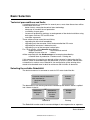

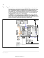
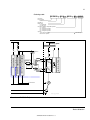

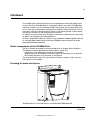
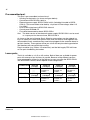
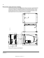
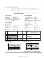
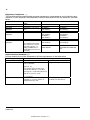
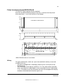
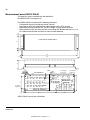
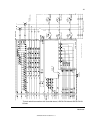
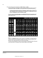
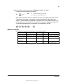
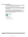
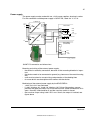
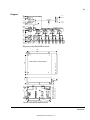
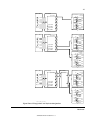
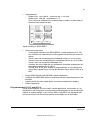
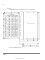
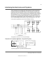
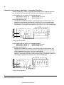
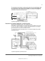
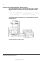
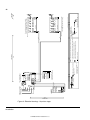
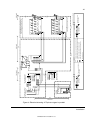
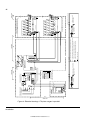
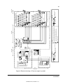
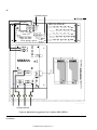
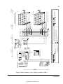
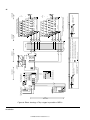
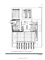
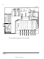
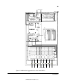
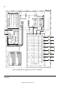
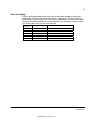
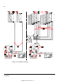
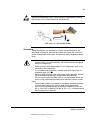


![Antares SB-GSM User`s Manual [FW5.30]](http://vs1.manualzilla.com/store/data/005924073_1-5fee82d33b9684441f88f249063588d6-150x150.png)