1
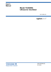
Dishwasher
Service Manual
Fully Integrated Direct Feed
Model Dishwashers
5995477345
October 2006
SAFE SERVICING PRACTICES - ALL APPLIANCES
To avoid personal injury and/or property damage, it is important that Safe
Servicing Practices be observed. The following are some limited examples of
safe practices:
1. DO NOT attempt a product repair if you have any doubts as to your ability to
complete it in a safe and satisfactory manner.
2. Before servicing or moving an appliance:
• Remove the power cord from the electrical outlet, trip the circuit breaker to
the OFF position, or remove the fuse.
• Turn off the gas supply.
• Turn off the water supply.
3. Never interfere with the proper operation of any safety device.
4. USE ONLY REPLACEMENT PARTS CATALOGED FOR THIS APPLIANCE.
SUBSTITUTIONS MAY DEFEAT COMPLIANCE WITH SAFETY
STANDARDS SET FOR HOME APPLIANCES.
5. GROUNDING: The standard color coding for safety ground wires is GREEN,
or GREEN with YELLOW STRIPES. Ground leads are not to be used as current
carrying conductors. It is EXTREMELY important that the service technician
reestablish all safety grounds prior to completion of service. Failure to do so
will create a hazard.
6. Prior to returning the product to service, ensure that:
• All electrical connections are correct and secure
• All electrical leads are properly dressed and secured away from sharp
edges, high-temperature components, and moving parts
• All non-insulated electrical terminals, connectors, heaters, etc. are
adequately spaced away from all metal parts and panels
• All safety grounds (both internal and external) are correctly and securely
connected
• All panels are properly and securely reassembled
ATTENTION!!!
This service manual is intended for use by persons having electrical and mechnical
training and a level of knowledge of these subjects generally considered acceptable in the
appliance repair trade. Electrolux Home Products, Inc. cannot be responsible, nor assume
any liability, for injury or damage of any kind arising from the use of this manual.
© 2006 Electrolux Home Products, Inc.
2
TABLE OF CONTENTS
Safe Servicing Practices ------------------------------------------------------------------------------------------- 2
The Design and Operation of the Fully Integrated Dishwasher --------------------------------------- 5
PLD4555RFC ----------------------------------------------------------------------------------------------------- 5
PLD4375RFC ----------------------------------------------------------------------------------------------------- 5
LEDB500FEE ----------------------------------------------------------------------------------------------------- 5
Cycle Selections ------------------------------------------------------------------------------------------------------ 6
Ulimate Scrub ---------------------------------------------------------------------------------------------------- 6
Maxx Clean ------------------------------------------------------------------------------------------------------- 6
Speed Clean ------------------------------------------------------------------------------------------------------ 6
Normal Wash ----------------------------------------------------------------------------------------------------- 6
China/Crystal ---------------------------------------------------------------------------------------------------- 6
Eco Wash --------------------------------------------------------------------------------------------------------- 6
Top Rack, Glasses and Party Glasses ------------------------------------------------------------------- 6
Rinse Only -------------------------------------------------------------------------------------------------------- 6
Favorite Cycle --------------------------------------------------------------------------------------------------- 6
Option Selections ---------------------------------------------------------------------------------------------------- 7
Wash Pressure -------------------------------------------------------------------------------------------------- 7
Wash Temperature --------------------------------------------------------------------------------------------- 7
Sanitize Rinse --------------------------------------------------------------------------------------------------- 7
Dry ------------------------------------------------------------------------------------------------------------------- 7
Delay Start -------------------------------------------------------------------------------------------------------- 7
Control Lock ----------------------------------------------------------------------------------------------------- 8
Digital Display --------------------------------------------------------------------------------------------------- 8
Status Indicators ----------------------------------------------------------------------------------------------------- 8
WASHING --------------------------------------------------------------------------------------------------------- 8
DRYING ------------------------------------------------------------------------------------------------------------ 8
CLEAN ------------------------------------------------------------------------------------------------------------- 8
SANITIZE ---------------------------------------------------------------------------------------------------------- 8
Rinse Agent LOW ----------------------------------------------------------------------------------------------- 8
Wash System ----------------------------------------------------------------------------------------------------------- 8
The Alternating Wash System -------------------------------------------------------------------------------------- 9
Part in the Wash System --------------------------------------------------------------------------------------------- 10
Wash Pump ------------------------------------------------------------------------------------------------------- 10
Stainless Steel Filter --------------------------------------------------------------------------------------------- 10
Lower Spray Arm ------------------------------------------------------------------------------------------------- 11
Center Spray Arm ------------------------------------------------------------------------------------------------ 11
Upper Spray Arm ------------------------------------------------------------------------------------------------- 11
Drain Pump -------------------------------------------------------------------------------------------------------- 11
Drying System ---------------------------------------------------------------------------------------------------------- 12
Fan/Vent Assembly ---------------------------------------------------------------------------------------------- 12
Heater --------------------------------------------------------------------------------------------------------------- 13
Door Baffles ------------------------------------------------------------------------------------------------------- 13
Dispensing System ---------------------------------------------------------------------------------------------------- 13
Dispenser Operation -------------------------------------------------------------------------------------------- 13
Door Latch Assembly ------------------------------------------------------------------------------------------------- 14
Fill System --------------------------------------------------------------------------------------------------------------- 14
Door Hinge and Spring ----------------------------------------------------------------------------------------------- 14
3
The Control System --------------------------------------------------------------------------------------------------- 15
Soil Sensing ------------------------------------------------------------------------------------------------------- 15
Temperature Controls ------------------------------------------------------------------------------------------- 15
Service Tests ------------------------------------------------------------------------------------------------------ 16
Water Temperature Test ----------------------------------------------------------------------------------- 16
To Activate the Water Temperature Test --------------------------------------------------------- 16
Water/Service Test ------------------------------------------------------------------------------------------ 16
To Start the Test ---------------------------------------------------------------------------------------- 16
To Exit the Water/Service Test --------------------------------------------------------------------- 16
Chart for the Water/Service Test ------------------------------------------------------------------- 17
Relay/Triac and Sensor Test ----------------------------------------------------------------------------- 17-18
Control Codes ----------------------------------------------------------------------------------------------------- 19
Disassembly and Service -------------------------------------------------------------------------------------------- 20
Safety Precautions ----------------------------------------------------------------------------------------------- 20
Control Panel ------------------------------------------------------------------------------------------------------ 20
Electronic Control ------------------------------------------------------------------------------------------- 20
Display --------------------------------------------------------------------------------------------------------- 20
Door Latch --------------------------------------------------------------------------------------------------------- 21
Door Strike --------------------------------------------------------------------------------------------------------- 21
Detergent/Rinse Aid Dispenser ------------------------------------------------------------------------------- 21
Door Hinge--------------------------------------------------------------------------------------------------------- 21
Door Seal ---------------------------------------------------------------------------------------------------------- 22
Bottom Door Seal ------------------------------------------------------------------------------------------- 22
Upper Rack -------------------------------------------------------------------------------------------------------- 22
Tub Roller Assembly -------------------------------------------------------------------------------------------- 22
Center Spray Arm ------------------------------------------------------------------------------------------------ 22
Upper Spray Arm ------------------------------------------------------------------------------------------------- 22
Lower Spray Arm, Spray Arm Support and Filter --------------------------------------------------------- 23
Heating Element -------------------------------------------------------------------------------------------------- 23
Float Switch and Mount Bracket ------------------------------------------------------------------------------ 23
Water Valve -------------------------------------------------------------------------------------------------------- 23
Drain Pump -------------------------------------------------------------------------------------------------------- 24
Replacing the Drain Pump -------------------------------------------------------------------------------- 24
Pump and Motor Assembly ------------------------------------------------------------------------------------ 24
Remove motor from sump -------------------------------------------------------------------------------- 24
Delivery Tube ----------------------------------------------------------------------------------------------------- 25
Vent and Fan Assembly ---------------------------------------------------------------------------------------- 25
Exploded Views -------------------------------------------------------------------------------------------------------- 26-34
Control Panel ------------------------------------------------------------------------------------------------------ 26
Door - model LEDB500FEE0 --------------------------------------------------------------------------------- 27
Door - models PLD4375RFC0 & PLD4555RFC0 -------------------------------------------------------- 28
Tub
------------------------------------------------------------------------------------------------------------- 29
Motor & Pump ---------------------------------------------------------------------------------------------------- 30
Frame ------------------------------------------------------------------------------------------------------------- 31
Racks - model LEDB500FEE0-------------------------------------------------------------------------------- 32
Racks - model PLD4375RFC0 ------------------------------------------------------------------------------- 33
Racks - model PLD4555RFC0 ------------------------------------------------------------------------------- 34
Service Data Sheet ---------------------------------------------------------------------------------------------------- 35-36
4
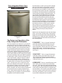
Fully Integraded Direct Feed
Model Dishwashers
PLD4555RFC
Figure 1
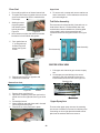
The Design and Operation of the
Fully Intergraded Dishwasher.
The fully integrated control places all cycle selection
and options on top of the console out of sight with
the door closed. With the controls under the counter
top while in operation, the cycle selection needs to
be accomplished with the door opened. First select
a wash cycle and any options, then press the Start/
Cancel pad or a Delayed Start pad and close the
door the cycle begins. A display mounted in the front
of the console shows the time remaining of the delay
or the time remaining in the cycle. While in operation,
the dishwasher control monitors the progress of the
cycle to determined if changes need to be made to
improve the cycle performance. Changes to the
cycle can start as early as the first fill, if food soils in
the water deems it necessary. If the user wishes to
make a change to the cycle, it needs to be done
before the completion of the first fill. After that time
any changes to a wash cycle will require a Cancel/
Drain before a new wash cycle can be selected.
While in operation, the control monitors all aspects of
the cycle with the use of sensors mounted in the
sump. These sensors enable the control to adjust
the length of the cycle based on soil level and water
temperature and are made as needed.
As stated earlier, a wash cycle can not be changed
after the first fill without a Cancel/Drain, options to
the wash cycle can be changed at any time up to
the point they are to be applied. If at any time after
the cycle has been started, the door is opened the
unit will stop, by closing the door the operations will
resume without pressing the Start/Cancel pad. If a
cycle needs to be terminated after the first fill has
started touching the Start/Cancel pad once sends
the unit into a Cancel/Drain for 90 seconds, this
terminates this selection. If while in a Cancel/Drain
the Start/Cancel pad is pressed a second time the
drain action stops immediately. At the completion of
a wash cycle the control lights the Clean indicator;
this indicator remains on until the door is opened.
After the wash cycle is completed and the door
opened when the Start/Cancel pad is pressed for a
new load the control will repeat the previous run
cycle, including all of the previously selected
options.
Added to the fully integrated control, the new design
offers, a new control console which is decreased in
height. The vent and door latch release handle that
had added to the height have been redesigned. The
towel bar handle once decoration now becomes the
door opening handle.
PLD4555RFC This is a 5 speed Professional
model with 6 wash cycles and a Rinse only cycle.
This model has preprogrammed wash pressure,
water temperatures, and dry options for each of the 6
different wash cycles. The user has the option to
change these setting to accommodate their desires.
See Figure 1
PLD4375RFC This is a 3 speed Professional
model with 6 wash cycles and a Rinse only cycle.
This model has preprogrammed wash pressure,
water temperatures, and dry options for each of the
6 different wash cycles.
LEDB500FEE This is a 5 speed Elements model
with 5 wash cycles, a Favorite cycle, and a Rinse
only cycle. This model has preprogrammed settings
for motor speed , water temperature and dry for each
of the wash cycles with the option to change these if
the user wishes. The Favorite Cycle selection allows
the user to program a wash cycle with any options to
their liking, then hold this cycle in memory by pressing one pad the designed cycle is repeated.
5
Cycle Selections
Normal Wash
This cycle is for normally soiled dishes. The control
automatically selects the Normal speed for the wash
motor, an assured water temperature of 135°in the
main wash and 140° in the final rinse. All of the
options are available and soil sensing will be used.
PLD4555RFC
China/Crystal
This cycle is for delicate crystal or china. The control
automatically selects the Delicate speed for the wash
motor, an assured water temperature of 130°in both
the main wash and the final rinse. Only the Air Dry
and the Delay Start options are available. Soil
sensing will not be used.
PLD4375RFC
LEDB500FEE
Eco Wash
Figure 2
To better understand these different wash cycles the
following are each cycle, the settings and what
options are available.
Ultimate Scrub
This cycle is used for heavily soiled dishes. The
control automatically selects the High speed for the
wash motor, an assured water temperature of 140°in
the main wash and 155° in the final rinse, and dry is
a default to Sahara. All of the options are available
and soil sensing will be used.
Maxx Clean
This cycle is used for heavily soiled dishes. The
control automatically selects the Maxx wash speed
for the wash motor, an assured water temperature of
140°in the main wash, 155° in the final rinse, and dry
is default to Maxx. All of the options are available
and soil sensing will be used.
Speed Clean
This cycle is for lightly soiled dishes The control
automatically selects the Normal speed for the wash
motor, an assured water temperature of 135°in the
main wash and 140° in the final rinse. All Wash
Pressures, Dry Options, and Delay Start options are
available. The Wash Temperature option is not
available and soil sensing will not be used.
Top Rack, Glasses, or Party Glasses
This cycle is used for small loads of glassware or
cups. The control automatically selects the Normal
speed for the wash motor only an assured water
temperature of 135° is set for the final rinse. The
water temperature options, dry options, and Delay
Start are available. Soil sensing will not be used.
Rinse Only
This cycle is intended to rinse dishes that will be
washed at a later time. There are no options
availably with the exception of a Delay Start.
Favorite Cycle
This is a cycle programmed by the user and gives
them a short cut to a cycle they use frequently. To
program the Favorite Cycle make the selection of a
wash cycle and all of the desired options, press and
hold the Favorite Cycle pad for three seconds.
Once the Favorite Cycle has been set the following
indicators will flash Time remaining, Favorite Cycle,
the user’s selected cycle and all options selected.
These lights will flash for 2 seconds. The Favorite
cycle can now be set as a wash cycle with the Start/
Cancel pad.
This cycle is used for a small dish load or lightly
soiled. The control automatically selects a High /
Maxx wash speed on the wash motor, an assured
water temperature of 125° in the main wash and
128° in the finial rinse. Only the Dry Option and
Delay Start options are available. Soil sensing is
used.
6
Option Selections
PLD4555RFC
PLD4375RFC
LEDB500FEE
Figure 3
Option selections allow the user flexibility to alter a
wash cycle to their desires. These options are the
speed of the wash motor this will increase water
pressure sprayed on the load, the temperature of
water in both the main wash and finial rinse segment of a cycle, the dry can be a no heat dry or on
some models the heated dry can actually be
extended for a longer time. This section cover
these and a delay start option.
Wash Pressure
This option allows the user to raise or lower the
speed of the wash motor which increases or decreases the pressure of the water used to clean the
dishes. The control will not allow this change in all
cycles because of the intent of the cycle. This
change in water pressure will effect all of the washes
and rinses in this selected cycle.
Depending on model, the option could read either
“High” or “Maxx” speed. This selection will
substitute the speed of the motor to 3400 rpm when
spraying from the lower spray arm and 3200 rpm
from the upper and center arms. This overrides the
variable speed function of the selected cycle.
Delicate Pressure limits all wash and rinse speeds
to 2800 rpm only for the selected cycle.
Wash Temperature
This option allows for the selection of a high temperature wash in select cycles. The high temperature wash occurs at the end of the main wash
segment of the cycle.
The display will flash an HO on models so equipped.
This option will increase the water temperature to
140°. There is a time override for this option of not
more then 10 minute.
Sanitize Rinse
The Sanitize rinse increases the finial rinse segment
to a temperature of 155° on select wash cycles. On
models PLD4555RFC and LRDB500FEE when the
sanitize rinse option is selected this selects the High
Temp wash as well, for that reason, both the Sanitize
and Hi temp wash indicators will light. On other
models, this is a separate option. There can be up to
30 minutes delay for the Sanitize rinse when selected. On models with a display, an HO will flash
during this delay period. Once the wash cycle is
completed, the Sanitize light and the Clean light are
light and remain on until the door is opened. If the
155° was not reached in the allotted time, the
Sanitize light will not come on informing the user the
criteria for this setting was not met.
Dry
This option, on all models, can disable the heating
element which gives only an air dry. There is an
active vent and fan assembly located in the top right
back corner of the tub that will be activated at the
end of all wash cycles. On select models, the Dry
option also offers a Max or a Sahara dry, this setting
lengths the dry cycle by 20 minutes to insure a dry
load. If when the dishwasher is in the dry cycle the
door is opened and stays open for more then one
minute the remainder of the dry cycle will cancel out.
Delay Start
This option allows for a wash cycle to be programmed into the control and the start delayed for a
set number of hours. A cycle can be delayed from 1
to 24 hours in 1 hour increments. To set a Delay
Start a wash cycle with options is selected followed
by pressing the Delay Start pad. Each time the Delay
Start pad is pressed in 3 second intervals the number
of hours to delay will increase by one hour up to 24
hours. Once the delay begins, time is decreased in
one hour segments until one hour remains, then the
count down changes to minutes. After the count
down starts pressing the Start/Cancel pad will have
no effect on the delay start, if the Start/Cancel pad is
a second time in succession this will cancel the delay
and start the selected cycle.
7
Control Lock
The control lock disables the keypad so that the
settings entered into the control can not be changed.
To activate the control lock press and hold the Delay
Start pad for 3 seconds with the dishwasher door
closed. The Control Lock indicator will illuminate
when the lock is set. To remove the control lock
press and hold the Delay Start pad for 3 seconds
until the light goes out. If the control lock is used, it
should be turned off after the cycle is completed and
before the door is opened.
If the control lock was used and not turned off before
the dishwasher door is opened the light will go out
with the control still locked, resulting in a non functioning dishwasher. This can be corrected by
removing power from the unit this will reset the
control.
Digital Display
The digital display is to indicate the current status of
the cycle. The display is a two digit display so time
will read from 1 to 99 minutes. If a cycle length is
over 99 minutes, the display will have a plus sign (+)
to the right of the numbers. This plus sign (+) will
stay light until the cycle time drops below 99 minutes. The display may also have codes appear to
indicate the status of the cycle or the condition of the
dishwasher. The most common of these codes is an
HO code which may appear and flash in the display,
this indicates that the control has delayed the cycle
to increase the water temperature. Another of these
codes is a flashing CL indicates of an open door.
This code can appear if the control is programmed
and the Start/Cancel pad is pressed before the door
is closed. Close the door and the cycle will start.
The last of the common codes is a PF code. This
will flash in the display on initial power up of the
dishwasher or any time power to the dishwasher has
been interrupted. There are fault codes that can
appear in the display as well; these will be listed as
failure codes in the control test section of this
manual.
The CLEAN indicator is energized at the end of all
wash cycles with the exception of a Rinse and hold
cycle. The clean indicator will remain on until the
door is opened. After the door is open, ALL indicators
will be extinguished with the exception of the “Rinse
aid low” if applicable.
The SANITIZE indicator is shown in the front display
as an “S” and will be energized at the end of any
cycle that the Santi option has been selected. The
sanitize criteria must be completed correctly for this
indicator to come on. This indicator will be extinguished when the door is opened.
The Rinse Agent LOW indicator on the keypad will
be on any time the rinse aid level in the dispenser is
low. This light will stay on until the dispenser is filled.
The indicator can also be extinguished after 5
successive cycles have been run with out filling the
dispenser. On select models an Lo will appear in the
front display to indicate the rinse aid dispenser is low
on agent.
Wash System
The wash system consists of wash pump and motor
assembly to provide water under pressure for the
three spray arms used to clean the dishes. These
three spray arms will alternate operation starting with
the lower spray arm. After a predetermined time the
spray will change to the center and upper spray arms
simultaneously.
Status Indicators
The WASHING indicator is energized at the beginning of any wash cycle and will remain on as long as
the vent actuator is not energized.
The DRYING indicator is energized when the vent
actuator is energized and remains on until the end of
the cycle regardless of which drying option is selected.
8
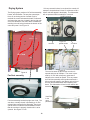
Figure 4
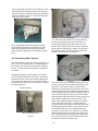
Below the lower spray arm is the filter and soil
director this covers the complete sump. The filter is
intended to block loosened food particles from
entering the wash sump area as they fall to the
bottom from the spray action. See Figure 4
On the underside of the filter is a soil director which
directs the loosened food particles to the lower left
side of the sump to a stainless steel food macerator
used to pulverize the soil so it can pass through the
drain hose. See Figure 5
Figure 5
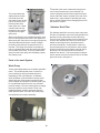
The remaining parts in the wash system are the
sump assembly that acts as a reservoir for clean
water being supplied to the wash pump and the
delivery tube to supply water to the upper two spray
arms.
Figure 7
The check ball rests at the end of a ramp molded
into the sump partially blocking the rear hole. As
water under pressure enters the volute cover, the
check ball is held tightly into the rear hole restricting
water flow from this opening. Water can only leave
the remaining hole from the top of the volute cover
into the lower spray arm. See Figure 7
The Alternating Wash System
This wash system is designed to spray from only one
arm or one set of arms at a time. The advantage of
this is that it reduces the amount of water needed in
the tub. The way this system operates is explained
as follows.
Alternating the spray is achieved with a check ball
moving between two holes in the sump. One hole is
located in the rear of the sump used to supply water
to the upper two spray arms; the second is located
out the top of the volute cover onto which is mounted
the lower spray arm.
Bypass opening
Ball covering back hole
Figure 6
Volute cover
Opening to
lower spray
arm
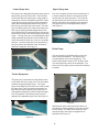
Figure 8
The force of the water entering and leaving the arm
causes it to turn by the positioning of the hole in the
spray arm. The rear hole which is molded in the
sump has a small section removed above where the
check ball sets, this section allows a small amount of
water to by-pass the check ball and enter the delivery
tube mounted up the out side rear of the tub. Water
by-passing the check ball will fill the delivery tube at a
rate of approximately four inches a second. This
water will be used to change the spray from bottom
to the upper two spray arms. All wash and rinse
cycles will start by spraying from the lower wash arm.
Changing spray from bottom to upper spray arms is
accomplished with the control stopping the wash
pump for not more then .6 of a second. This pause
removes water pressure from the rear of the check
ball, water that had accumulated in the delivery tube
now reenter the sump, which moves the check ball
away from the hole and up the ramp.
9
Ball at the top of ramp
opening hole to center arm
The pump restarts the
water pressure in back
of the ball forces the
check ball up into the top
hole in the volute cover
blocking water tothe
lower spray arm. Water
exits the rear hole into
the delivery tube supplying water to the upper
spray arms.
The speed of the motor is determined by the electronic control based on the cycle selected. The
control continually monitors motor speed with input
from a Hall Effect sensor mounted to the rear of the
wash motor. Input voltage for operating the motor
will be 120VAC with the motor changing this to VDC
with a built-in rectifier.
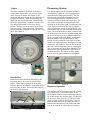
Stainless Steel Filter
Figure 9
Water in the delivery tube is divided with 80% going
to the center spray arm and 20% to the upper arm.
Water spray will continue from the upper spray arms,
after a predetermined time the control will again
pause the pump this time the pause will be for 3
seconds. This longer time allows for the delivery
tube to completely drain then the check ball returns
to the bottom of the ramp. The pump restarts with
spray from the lower spray arm completing a spray
arm change cycle.
The stainless steel filter covers the entire sump area.
The filter is intended to remove all food particles from
the water so only clean water reenters the sump.
There is a fine mesh polyester screen housing in the
center of the stainless steel filter to house a lift out
basket to catch larger items, this basket can be
removed for cleaning. On the bottom of the inner
screen housing there is a soil director used to direct
food soil removed from the dishes to the left side of
the sump to be removed first when the water is
drained from the tub. The lower spray arm support
is also used as a lock for the filter to insure it is down
tight to the sump. See figure 11
Parts in the wash System
Wash Pump
These model dishwashers use a variable speed DC
motor. The variable speed motor is used to improve cleaning by varying the water pressure
depending on the cycle selected. An Ultimate
Scrub and Maxx cycle intended for heavily soiled
dishes will have a high pressure speed to better
remove baked on food where a China/Crystal cycle,
for very delicate items will have a very low water
pressure setting. The user has an option to change
the motor speed on some models. There is an
added advantage of quieter operation when the
lower speed is used. The motor and wash pump
are supplied as a one piece assembly.
Figure 11
Figure 10
10
Lower Spray Arm
This spray arm is designed using three spray arms to
spray water up into the lower rack. There are also
on the underside of this spray arms 4 legs used for
cleaning the soil from the stainless steel filter. Three
of the legs have spray openings pointed toward the
center these will spray water across the top of the
filter forcing the loosen soil to the center. The forth
leg is mounted closer to the center of the spray arm,
with a spray opening pointed straight down forces
food collected in the center basket down into the soil
director for removal in the drain segment of the wash
cycles. Turning of the arm is accomplished by water
under pressured sprayed from holes molded on top
of the arm these force the arm to turn in a clockwise
direction. The lower spray arm turns periodically in
all cycles, this to keep the filter clean, and reduce
Upper Spray arm
This arm is located in the top of the tub and turns in
a counter clockwise direction, and sprays simultaneously with the center spray arm. The mount for
the upper spray arm serves as the lock nut for the
delivery tube and is only available as an assembly.
The spray arm will turn at approximately 40 rpm.
See Figure 14
Figure14
chances of redeposit. See Figure 12
Drain Pump
The only function of the drain pump is to remove
water from the dishwasher. The drain pump is
mounted directly to the front of the sump. The
motor for this pump is rated a 1/25th hp drive motor.
The drain pump only comes as an assembly. The
front cover of the pump can be removed for cleaning
if needed.
Figure 12
Center Spray arm
This spray arm is mounted on a short delivery tube
to the under side of the upper rack. This arm rotates
clockwise at approximately 20 rpm. The center
spray arm and delivery tube will move in and out with
the upper rack. There is a bellows mounted to the
back end of this short delivery tube which forms a
seal against the back wall of the tub when the spray
arm is in operation. This delivery tube is also designed for the adjustable upper rack. See Figure 13
Figure15
With the drain pump mounted in this location it is
accessible by removing both the outer door and the
toe kick panels. The drain pump connector hose
from the pump to the sump are supplied as an
assembly. See Figure 15
Figure 13
11
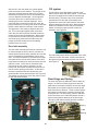
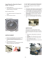
Drying System
The Drying system consists of a Fan/Vent assembly,
Heater, and Air Baffles. The way the systems performs is; as the dry portion of a wash cycle is
reached the control activates the heater, if selected,
and opens the vent door, located in the top right rear
of tub, this allows the vent fan to draw in outside air
resulting in hot air being forced out the bottom of the
outer door panel. See Figure 16
If for any reason this door is not closed, the control will
attempt to close the door 5 times if it continues to fail a
failure code will appear in the display. The dishwasher
will not operate until this condition is corrected.
12 VDC solenoid
Dry
(exhaust fan on)
Figure 18
vent fan
optical sensor
vent door
Air Flow
Figure 19
The vent fan starts as soon as the vent door is
opened and turns at 3500rpm. The motor is powered by 12 VDC with a frequency generator to
indicate to the control fan speed. If for any reason
the Fan/Vent assembly would get disconnected, a
failure code will appear in the display on the front of
the door and the dishwasher will completely shut
down. The dishwasher will not function without this
assembly.
Figure 16
Fan/Vent assembly
Figure 17
Fan/Vent assembly located top right rear of tub. The
vent door, normally closed, is opened by a 12 VDC
solenoid also mounted in the assembly. There is an
optical sensor to indicate to the dishwasher control
that the vent door is properly closed until it is to be
opened. See Figure 17 & 20
12
Vent Door
in the
open
possition
Figure 20
Dispensing System
Heater
The heater mounted in the bottom of the tub increases water temperature, then in the dry cycle
assist in drying the dishes. See Figure 21 The
amperage draw of the heater can vary depending on
the job it is to perform. When heating water, the
amperage draw can be 900 watts. This amperage
will drop to approximately 700 watts in the dry cycle.
The design of the heater is to be more energy
efficient. Mounted next to the heater on the under
side of the tub is a safety thermostat. This thermostat will open if the temperature in the tub raises over
200°F. See Figure 22
The detergent and rinse aid dispenser consists of
two dispensers combined in one housing and are
controlled with one wax motor actuator. The first
time the control energizes the actuator the cover
over the detergent side of the dispenser opens
dispensing detergent for the main wash cycle. The
second time the actuator is energized rinse aid is
released for the final rinse cycle. The detergent side
of the dispenser consists of two cups: the smaller
cup is for detergent used in the pre-wash cycle, the
second larger cup is for the main wash section of the
cycle. The rinse aid section contains a reservoir that
will hold enough rinse aid for many applications. See
figure 24 This reservoir has an indicator that will be
clean if rinse aid needs to be added. A reed switch
has been added to the rinse aid dispenser that
informs the control when the rinse agent is low the
control then displays and LO in the display to inform
consumer of this condition. There is also an adjustable hub inside the dispenser, seen by removing the
cap, to control the amount of agent dispensed. This
detergent and rinse aid dispenser is replaced as a
complete assembly. The cap for the rinse aid dispenser is the only part available for this dispenser.
Figure 21
Figure 22
Door baffles
Baffles have been installed into the bottom of the
inner door panel to direct hot air out of the dishwasher. Foam baffle is mounted to the outside
bottom of the inner door panel to keep steam and air
from rising into the door. This foam baffle most not
be removed. See Figure 23
Door baffle
Do Not Remove
Figure 24
Dispenser Operation
The dispenser has two detergent cups both covered
by the same cover. In the bottom center of the
spring loaded cover is a thumb release. By pushing
up on this release, the cover will open. The larger of
the two cups, under the cover, is used for the main
wash cycle the smaller for the pre-wash. With the
detergent added the cover is closed. The cover is
slotted so the detergent from the smaller pre-wash
cup can be washed out without the cover opening.
Figure 23
13
After the fill in the main wash, the control applies
power to the wax motor actuator. The plunger of the
wax motor extends pressing down on a pivot arm
attached to the latch for the cover, this releases the
cover to dispense the detergent. On the opposite
end of this pivot arm is a pin that rides up in the
actuating arm for the rinse aid dispenser. Once
power has been removed from the wax motor, the
plunger retracts the pin riding in the rinse aid actuator
follows a track down the back side of the actuator.
The dispenser is now ready to dispense the rinse
aid. The control again applies power to the wax
motor the pivot arm raises the rinse aid actuator to
release rinse aid into the dishwasher. When power
is removed from the wax motor the pivot arm falls
and a leaf spring mounted to the side on the dispenser forces the actuator arm to the starting
position for the next cycle.
Fill system
The fill system of this dishwasher consists of the
water fill valve and a float safety switch. Power from
the control is applied to the water fill valve through
the float safety. The water valve is an electrically
operated shut off valve with a flow washer that
regulates the amount of water based on the water
pressure applied to the valve inlet. Water pressure
needs to be between 20 and 120 psi for the dishwasher to have the proper amount of water for
operation. See Figure 26
Door latch assembly
The door latch assembly performs two functions: first
to close and latch the door to the tub, second is to
actuate both of the door safety switches to insure the
door is closed before the dishwasher can be operated. The latch mechanism is mounted to the inside
door panel with a lock tab at the bottom of the latch
body and two location pins on the back then secured
with two screws. As the door is closed the strike
mounted to the top of the tub presses in on the
locking cam and rotates it forward this raises a lock
into the center opening of the strike. As the cam in
the latch is pressed forward it releases the door
switch actuator closing both switches. See Figure 25
The handle mounted to the outer door panel is used
to open and close the door
Figure 26
The float safety switch will shut off power to the valve
if the tub over fills with water. Water enters the tub
through an air gap mounted to the left side of the tub.
See Figure 27
Door Hinge and Spring
Figure 27
The inner door panel is attached to the tub frame by
hinges. On the face of both hinges there are fiber
pads that act as breaks to hold the door at any angle,
these pads do not interfere with the smooth up and
down movement of the door. There are door springs
and cables on both hinges to assist in opening and
closing the door. The door spring, which is attached
to the rear frame, has a cable that passes around a
friction bearing before attaching to the door hinge.
This spring and cable assembly provides a quieter,
smoother, operating door. See Figure 28
Locking Cam
Spring
Cable
Bearing
Figure 25
Figure 28
14
The number of times the control checks the soil level
varies with cycle but in cycles it is used the pre-wash
water will always be checked. The control can
increase a cycle length or decrease as needed but
never longer then the longest cycle or shorter then
the shortest cycle available.
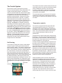
The Control System
The electronic control, with input from various
sensors, has total operation of the dishwasher once
a wash cycle has been started. The electronic
control is mounted inside the console with its power
coming directly from the power junction box. Power
to operate the control can not be interrupted by
opening or closing the door. However, the control
does know when the door is opened. The black
power lead from the door switch is attached to the
control this line operates all of the components in the
dishwasher. Input to the control comes from the
following: the keypad is a membrane switch that
allows the user to select a specific wash cycle and
any available option for the dishwasher to perform, a
soil sensor that determines the concentration of soil
in the water, a thermistor to measure the temperature of the water, a Hall sensor to track the speed of
the motor, an optical sensor reports the position of
the vent door, finally a reed switch in the rinse aid
dispenser to report the pressents of rinse aid in the
dispenser. This section will describe the sensors
how they operate followed by tests that can be
performed to test the control system and all of the
components in the dishwasher.
The control pauses the wash motor for 30 seconds
to allow time for the water to settle before checking
then the water is drained and any adjusts to the cycle
are made.
Temperature controls
The control is programmed with preset wash and
rinse temperatures for each cycle. The use of a
thermistor in the sump provides water temperature
information to the control to maintain these temperatures. The control provides options for the user to
select a higher temperature wash as well as a
sanitize rinse.
Soil Sensing
A soil sensor is used by the control to make adjustments to length of wash cycles based on the soil
level found in the water. This sensor is located in the
base of the sump directly in front of the wash motor
intake. The soil sensor receives a voltage signal from
the control which it converts into a small beam of
light; the transmitter then directs this light beam to a
receiver through water that has been used to prewash the load in the unit. As the light passes through
the water the density of the water can reduce the
strength of the light beam reaching the receiver. The
receiver turns the light back to a voltage this is then
returned to the control, which interprets this reading
and adjusts the cycle length accordingly. See Figure
29
Thermistor
Soil sensor
.
The thermistor is located in the same housing as the
Soil Sensor. The post on the Soil Sensor that is taller
is the location of the Thermistor. With the sensor in
the water of the sump it gets a more accurate reading
of water temperature. See Figure 29
To insure the pre-programmed water temperature for
the wash cycle is reached the control can pause the
main wash cycle up to 10 minutes in a Temp assure
cycle. This Temp assure cycle is automatic and not
selected as an option. If the Hi-temp wash option is
selected, the control will delay the main wash section
once again for up to10 minutes to increase the water
temperature to a higher degree. Whether or not the
water temperature is reached in this10 minutes delay,
the cycle will continue without indication that it
reached or did not reach this temperature.
When the Sanitize option is chosen, the National
Sanitation Foundation requires in the final rinse cycle
that 155°F be reached and maintained for a certain
amount of time. During the final rinse, the control
pauses the time remaining for up to 30 minutes to
reach this 155°F temperature before proceeding to
the end of the cycle. Should the cycle meet the
requirements defined for the sanitize option, the
Sanitize light will come on and stay on until the door
is opened. If the requirements are not met the
sanitize light will not come on at the end of the cycle.
Figure 29
15
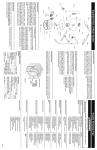
Water/Service Test
Service Tests
The control has a number of tests that have been
programmed into its memory most of these are for
manufacturing purposes and are not useful for field
service. At times, if certain pad combinations are
pressed, different codes may appear in the display
that are unknown or not listed, what needs to be
done is disconnect power to the unit then reconnect.
You can then continue with servicing the dishwasher.
The control has service tests programmed into it that
can be of assistance to the service technician in
diagnosing control and component problems with this
unit. These tests are; The Water /Service Test,
Water Temperature Test Mode, and The Relay/Triac
and Sensor Test.
To insure the correct pad is pressed to enter and use
these tests the pad locations will be numbered 1
through 11 with pad # 1 being the pad furthest to the
left an pad # 11 the furthest to the right. In all cases
the pad to the right will always be the Start/Cancel
pad.
In the Water/Service Test, the control will step
through each function of the product and operate
each component before ending and illuminating the
CLEAN and SANITIZE LED’s. Along with checking
the operating components the control will check all of
the input sensors as the test progresses, if at any
time a failure in one of these sensors is detected, the
test will stop and a failure code will be displayed.
To Start the Test
From an idle condition, this is with no programs
entered into the control, press pad # 10 and the
START/CANCEL simultaneously for three seconds.
You will know that the test has started by the water
valve being activated and the Washing and Sensing
LED lighting. The test will automatically advance
through the complete test unless the control detects
a failure in one of the sensors. The test may be
manually advanced by pressing the START/CANCEL
pad. Each time the pad is pressed the cycle is
advanced one segment.
Water Temperature Test
This test will allow the service technician to check the
temperature of the water in the sump of the dishwasher while at idle or while it is in operation. The
temperature of the water will show in the display
using the last two numbers in the degrees. On
temperature over two numbers the display will read
the last two numbers in the temperature and a plus
(+) sign, an example of this is the water in the sump
is 120° will read 20+ in the display.
To active the Water temperature test
With the dishwasher in idle press and hold the
Normal wash and the Start/Cancel pads simultaneously for 3 seconds the temperature will be shown
in the display. To terminate this test press and hold
the Normal wash and the Start/Cancel pads again for
3 seconds.
With the dishwasher in operation, press the cycle
selection pad of the cycle that is in operation and
hold in for 3 seconds the temperature will be displayed. The temperature will stay in the display and
update every 3 seconds. To terminate this test press
and hold the same cycle selection pad used to start
the test.
16
To Exit the Water serviceTest
At the end of the test the control lights the CLEAN
and SANITIZE LED’s. With these indicators light,
opening then closing the door will give a PF code in
the display, the START/CANCEL pad can now be
pressed to clear the test and restart the dishwasher.
1 0 0 0
1 0 0 0
1 0 0 0
1 0 0 0
0 1 0 0
0 1 0 0
0 1 0 0
0 0 1 0
0 0 0 1
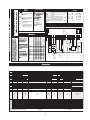
X- denotes a selectable option
SANITIZE and CLEAN LED stay on until door is opened or cycle started.
If the rinse agent is low in the dispenser LO will be displayed in the front display.
Relay/ Triac and Sensor Test
This test allows the servicer to troubleshoot the
dishwasher by energizing the different devices of the
dishwasher independently from one another. The
best way to understand the value of this test for field
service technicians is the example of testing the
heater for operation. Enter the test followed by
pressing pad number 10 on the keypad (see table)
this will apply power to the heater. The heater will be
powered until the same pad is pressed a second
time.
This test can only be entered from a PF (Power
Failure) condition. This can be accomplished in two
ways. First is to have the power removed from the
dishwasher then turned back on this will show a PF
in the display and the test can be entered.
1
1
1
1
0
0
0
0
0
Device
being
monitored
0 fan damper
0 turbidity
0 hall sensor
0
0
0 thermistor
0 fan speed
0 rinse aid
1
Display Flashes when
detection of failure
0
0
0
0
0
0
1
1
Clean LED
1
0
0
0
0
1
0
0
Sening LED
Fan unit
0
0
1
1
1
1
0
X
Sanitize LED
Dispensor
0
0
0
0
0
0
1
1
Drying LED
Heater
0
0
1
0
1
1
0
0
Rinsing LED
Drain Motor
1
1
0
0
0
0
0
0
Washing LED
Circulation motor
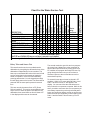
60
27
45
0.4
75
60
90
90
447
Water valve
DESCRIPTION
FILL/DISPENSER
FILL
WASH/HEAT (3450rpm)
PAUSE
WASH/HEAT (2800rpm)
WASH/HEAT/DISP (3450rpm)
DRAIN
DRY
TOTAL
Total time, (sec)
Chart For the Water Service Test
uo
tu
hs
th
uF
rA
The second method to enter this test is to program
the control into a Water/Test, at the completion of
this test then open the door the control goes into a
PF condition now program the Relay/Triac test. By
going through the water test you do not have to
disconnect power to the unit and the test can be
entered rather quickly.
To access this test the unit must be placed in PF
condition. While in PF press and hold Pad # 1 and
Pad # 7 at which time an “rt” will appear in the
display. You can now follow the chart below as to
how to select the component to operate. While in this
test if you wish to test more then one component you
must always repress the previously selected pad to
leave one component before moving on two the next.
When the tests are completed you must again Press
Pad # 1 and the Pad # 7 this will return you to PF
mode.
17
Relay/Triac and Sensor Test
To access this test the unit must be placed in PF condition. While in PF press and hold Pad # 1 and Pad # 7
at which time an “rt” will appear in the display. You can now follow the chart below as to how to select the
component to operate. When the test is complete you must again Press Pad # 1 and the Pad # 7 this will
return you to PF mode.
Pad
1
Pad
2
FUNCTION
Start Test
Pad
3
Pad
4
Pad
5
PAD TO BE
PRESSED
Ultimate Scrub or
Maxx Clean & Rinse
Only
Pad # 1
Pad
6
Pad
7
FUCTION
PERFORMED
Pad
8
LED
ILLUMINATED
Ultimate Scrub
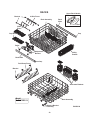
watervalve on/off or Maxx Clean
wash motor @
Speed Wash
2800 rpms
pad
wash motor @
Speed Wash
2950 rpms
pad
wash motor @
Speed Wash
3100 rpms
pad
wash motor
Speed Wash
@3450 rpms
pad
Active water valve
Test Variable Speed motor
Function #1
Test Variable Speed motor
Function #2
Test Variable Speed motor
Function #3
Test Variable Speed motor
Function #4
Pad # 2 (4 Times)
Stop Variable Speed Test
Heater on/off
Pad # 2 (5 Times)
Pad # 10
Detergent Dispenser
Pad # 3
Wash motor off
None
Heater on/off
No Heat Dry
dispenser
powered
Normal Wash
Rinse aid level
Pad # 7
none
Drain pump
Pad # 4
drain pump
on/off
Vent/ Fan dry
Pad # 5
Active vent
/off
Soil Sensor
Pad # 8
none
Thermistor
{Pad # 9
none
Pad # 2 (1 Time)
Pad # 2 (2 Times)
Pad # 2 (3 Times)
Pad
9
18
Rinse only
China Crystal or
Party glasses
Top Rack,
on Eco Wash
Glasses
Wash Silencer
or Wash
pressure
Wash
Temperature
Pad
10
Pad
11
IN DISPLAY
"rt"
valve on =FL Valve off =
rt
First two digits of motor
speed
First two digits of motor
speed
First two digits of motor
speed
First two digits of motor
speed
"rt"
on = HO
off = "rt"
on = Sd
low = RE
off = "rt"
off = "rt"
full = RF
on = dP
off = "rt"
on = Fan speed
off = "rt"
on = senser voltage
reading off = "rt"
on = Temperature in °F
off = "rt"
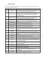
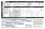
Control Codes
At time codes may appear in the display below are a list of codes. Not all codes are failure or error codes so
be sure to read what the code means.
Display
Reason for Code
"uo"
Vent open
"uF"
Fan is not running
"Er"
What it indicates
When is a wash cycle the control does not receive the proper indication that
the vent is closed. The control will try to reseat the vent if after 5 attempts
the vent does not close the failure will appear. The cycle will not start.
When in the dry mode, the control does not receive the proper feedback from
the vent that the fan is running at the proper speed. The failure will appear
and the control shuts down
Membrane Switch failure When the control verifies that any of the pads on the membrane switch has
been closed for one minute the failure will appear in the display
"CE"
Configuration error
CL
Door switch open
dP
Drain pump operations
FL
Water valve is on
HO
Heat delay
hs
Hall Sensor
LO
Low rinse aid
PF
Power failure
rA
Rinse aid
RE
Rinse aid
The reed switch in the rinse aid dispenser is closed. This can be seen in the r/t
test if pad # 7 has been pressed
RF
Rinse aid
The reed switch in the rinse aid dispenser is open. This can be seen in the r/t test
if pad # 7 has been pressed
rt
Relay/triac test
Sd
Detergent disp.
tu
Tubidity sensor
UL
UL test mode
On power up the control verifies a problem with the options the failure will
appear.
The control is not receiving power from the door switch
This will be seen in the r/t test if pad # 4 has been pressed
This will be seen in the r/t test if pad # 1 has been pressed
The control has extend the length of a cycle to allow for in increase in water
temperature
The control has sensed a problem with the Hall style sensor in the wash motor.
The control has received a signal form the rinse aid dispenser that the rinse agent
level is low.
The control has experienced drop in power to the processor
The control has sensed a problem with the reed switch in the Rinse aid dispenser
The control has entered the r/t test program
The detergent dispenser has been activated
The control has sensed a failure in the turbidity sensor while in the
Water Service test.
The control has been programmed for a UL test mode.
19
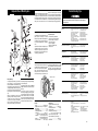
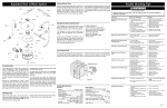
DISASSEMBLY AND SERVICE
SAFETY PRECAUTIONS
Always turn off electrical power supply before
servicing any electrical component, making ohmmeter checks, or making a part replacement. Refer to
safe service procedures at the front of this service
manual before servicing the dishwasher.
Red wire to heater
P3 connector
Ribbon for keypad
All voltage checks should be made with a voltmeter
having a full scale of 130volts or higher.
After service is completed, be sure all safety grounding circuits are complete, all electrical connections Black wire from door latch
Ribbon from Display
are secure, and all access panels are in place.
P2 connector
Figure 30
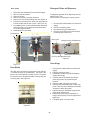
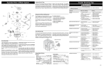
CONTROL PANEL
Display
Note:
Console will come as console assembly consisting 1. Disconnect the dishwasher from electrical supply.
2. Remove outer door panel
of the following; console, keypad (installed), and
3. Remove console from top of inner door panel
foam blocks around ribbon.
4. Remove control cover (3) mounting screws
1. Disconnect the dishwasher from electrical supply. 5. Disconnect plug from control to display
6. Press in on plastic retainer holding display in to
2. Remove the outer door panel;
console, push display out from rear. See Figure 31
a. The outer door panel is held to the inner
7. Reassemble in reverse order.
door panel by two screws and four
locking tabs, two on each side of the
door panel.
b. Remove the lower two screws, one on
each side that secures the outer door to
the inner panel.
c. Close the door and slide the door panel
down and outward to remove.
6. Remove the six remaining screws mounting the
control panel to the inner door.
plastic retainers
Electronic Control
1.
2.
3.
4.
5.
6.
Disconnect the dishwasher from electrical supply.
Remove outer door panel
Remove console from top of inner door panel
Remove control cover (3) mounting screws.
Remove wires and plugs connectors See Figure 30
Raise ribbon lock and remove ribbon from control
See Figure 30
7. Remove control
8. On installation make sure all wires are
connected in proper location and tight to
terminal.
Figure 31
20
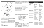
Door Latch
Detergent/ Rinse aid Dispenser
1.
2.
3.
4.
5.
6.
Disconnect the dishwasher from electrical supply
Remove outer door panel
Remove console
Remove wires from both door switches
Remove two Torx screw holding latch See Figure 33
Pull latch out at the top from inner door panel and up
to clear location tab on rear of latch. See Figure 32
7. On installing wires on door switches make sure both
white wires are on one switch and both black wires
are on the opposite switch.
8. Install latch in reverse order.
To diagnose operation of the dispenser use the
Water Service Test
See the section on testing the control system.
1. Disconnect the dishwasher from electrical
supply
2. Remove outer door panel
3. Disconnect wiring from dispenser
4. Remove six Phillips screws and carefully
push dispenser into the tub
Location pins
Wax motor
Lock tab
Mounting Screws
Reed switch connections
Pivot for detergent door latch
Figure 35
Figure 33
Door hinge
Figure 32
Door Strike
The door strike mounts to the top frame of tub with two
5/16 bolts the strike is not adjustable. The strike is the
part the door latch attaches to when closed. To replace
the tub will have to be pulled forward to access the two
mounting bolts. See Figure 34
Linkage to rinse aid dispenser
1. Disconnect the dishwasher from electrical
supply
2. Remove outer door panel
3. Dishwasher needs to be pulled forward to
replace door hinge
4. Check water line and drain hose before
removing counter top screws and pull
forward.
5. Remove cable and spring from hinge.
6. Remove bolts mounting hinge to inner door
panel. Take care not to damage foam baffle
at bottom of inner door panel.
7. Remove hinge pin hold hinge support with
pliers while removing pin.
8. Install hinge make sure the shoulder on
hinge pin is properly in hole in hinge before
tighten pin.
9. Complete repair in reverse order.
Figure 34
21
Door Seal
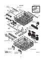
Upper Rack
1. Door seal just pulls out of channel around tub.
2. To replace find center of gasket make sure back
goes into channel first. Back is marked with a
color stripe.
1. To remove rack, unsnap and remove retainers at
end of metal track. Once retainers are removed,
pull rack straight out.
Tub Roller Assembly
3. Starting at center
top press gasket
into channel just to
hold in place See
Figure 36
There are two tub roller assembly, front and rear, on
both sides of the tub. Each assembly has a top
and a bottom rollers installed on a mounting plate
with molded in axles, these assemblies are
screwed into the tub using two screws. See Figure
41.
Figure 36
4. Go to bottom on either side find block molded
into bottom of tub fill block with gasket.
5. Form gasket into an
“L” press gasket up
channel in several
spots. See Figures
37&38
Rear Assembly
Front Assembly
Figure 37
Figure 41
CENTER SPRAY ARM
1. Pull upper rack forward to gain access to spray
arm.
2. Center spray arm and delivery tube are an
assembly, push this assembly to the rear to
loosen and remove from rack. See Figure 42
Figure 38
6. Repeat steps 4 and 5 for opposite side
7. Close door to seat seal.
Retaining clip
Bottom Door Seal
Center cut out
Figure 39
Bottom
1. Remove lower rack from tub
2. Open door completely down door seal can be
pulled out from the right side. See Figure 39 &
40
3. Pull straight into tub.
4. When installing new seal place seal in channel
just enough to hold in place
5. Close door for tub to push seal in place.
Figure 40
22
Figure 42
Push
Upper Spray Arm
To remove the upper spray arm turn the mounting
nut counter clockwise to unscrew from delivery tube.
If mounting nut is too tight place the handle end of
pliers into the notches and turn to remove.
Lower Spray Arm, Spray Arm Support
& Filter See Figure 43
1. Remove lower rack
2. Lower spray arm clips onto the lower spray arm
support lift spray arm off support
Spray arm support & Filter
1. Turn support clockwise 90° lift support from
sump.
2. Filter is now free to lift out
FLOAT SWITCH AND MOUNT BRACKET
Remove float by lifting up out of tube molded in
bottom of tub.
1. Disconnect the dishwasher from electrical supply
2. For ease of service, remove outer door panel
and the kick plate, remover wires to float switch.
3. Unscrew Phillips screw holding assembly to tub,
there is a hole provided in the actuator lever to
access screw. Screw will remain in assembly
once removed.
4. When installing Switch and bracket onto tub
make sure mount stays tight to tub. See Figure
46
Spray arm support
Lift out basket
Figure 46
Filter
WATER VALVE
Figure 43
Heater
HEATING ELEMENT
1. Disconnect the dishwasher from electrical supply
2. To remove element disconnect wiring and
remove two element mounting nuts. See Figure
45
3. Lift terminal ends from tub.
4. Raise locking hook on mounting brackets to slide
element from brackets. See Figure 44
Testing water valve and float switch is best
preformed by using the Water Service Test see
section on testing the control system to start this
test.
1. Disconnect the dishwasher from electrical
supply
2. Turn water off to dishwasher before replacing valve
3. Gain access to valve remove wiring, water
line, and fitting from valve.
4. Water valve is secured with two screws. See
Figure 47
Mounting
screws
Figure 44
Figure 45
Figure 47
23
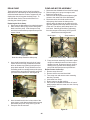
PUMP AND MOTOR ASSEMBLY
DRAIN PUMP
1. Disconnect the dishwasher from electrical supply
Testing the drain pump can be done by using the
2. Remove spray arm, spray arm support, and
Water Service Test following the test the drain pump
filters from inside of tub
will be activated when the number 7 appears on the
3.
Remove
outer door panel and kick plate to gain
display then check for power the drain pump. To
access
to
the under side of the dishwasher.
start the Water Service Test see the Section on
4.
Disconnect
wires from both wash motor and
checking the Control System.
drain pump, then loosen the clamp on the
Replacing the Drain Pump
delivery tube, the clamp can be reached on the
right side, between the sump and the side frame
1. Disconnect the dishwasher from electrical supply
of the unit. The delivery tube clamp has a 5/16
2. Gain access to drain pump remove wiring and
inch head. Carefully push delivery tube away
drain hose from pump. Slide clamp on sump
from the rear port of the sump. See Figure 50
end of the hose between pump and sump to the
center of hose
Wash motor mounting bracket
Wash motor
Sump retainers
Soil Sensor
Figure 48
Figure 50
clamp on the delivery tube Sump retainers
Slide this clamp toward the drain pump
3. Insert small screwdriver into top hole of pump
mount on front of sump, push down on screwdriver to release top mounting hook pull top of
pump back and hold. To help hold this out use
something small as a wedge between the pump
mount and the sump this will keep this out while
you move to the bottom lock. See Figure 48
5. Pump and motor assembly is secured in place
using four retainers that will turn into sump to
release from tub. Push sump into tub, then by
rotating to the right will aid in clearing wash
pump and drain pump as sump is lifted out.
Remove motor from sump.
1. Remove sump from tub
2. Remove volute cover and check ball
3. Turn sump over and remove motor mounting
bracket (2 screws)
4. Lift bracket from sump.
5. Return sump to up right position.
6. Place end of a flat blade screwdriver in front of
wash impeller and force motor out rear of sump.
SeeFigure 51
Figure 49
4. Insert screwdriver this time in lower hole of the
pump mount, push down and pull back on pump
will release pump from sump. See Figure 49
5. Pump can now be removed.
Figure 51
24
The following repairs will require removing the
dishwasher from under the counter. Before starting
the repair, disconnect the power to the product, also
make sure others are aware that you have turned
this off for your safety. Turn off the water supply to
the dishwasher and mark the valve as being turned
off this is again for safety. After the utilities have
been turned off, lower the dishwasher as much as
possible to prevent damage to the counter. Always
use floor protection as the unit is pulled forward.
8. Reinstall tube on to sump then install center
screw.
9. Tighten both upper spray arm mounting nut and
clamp on sump.
Vent and Fan Assembly
1. With the dishwasher removed from under the
counter either remove the upper rack or just pull
forward to access the vent assembly
Vent and fan assembly mounting nut.
DELIVERY TUBE
1. With dishwasher removed from under counter
top unscrew and remove the upper spray arm.
This unscrews counter clockwise.
mounting screw
tube
Figure 54
2. The locking collar holding the assembly in place
turns off to the left (counterclockwise). See
Figure 54
This is a very tight
fit pressing down
on the outside of
the assembly can
help in removing
part See Figure
55
Figure 52
2. Remove mounting screw in back of tub. See
Figure 52
3. Remove clamp from sump end of tub and
remove tube.
4. Check hole in back of tub for
grommet to be sure it is
smooth and no extra plastic
around opening
5. Install gourmet from inside
tub, outside flange must be
flat on back of tub. See
Figure 53
Figure 55
3. Installing new assembly be sure gasket is in
place and collar locks on completely to prevent
leaks. See Figure 56
outside flange
Figure 53
6. To install tube start by placing tube in top of tub
and installing upper spray arm loosely.
7. Place center opening of delivery tub into the tub.
Be sure to hold grommet in place while pressing
tube into opening.
Figure 56
25
CONTROL PANEL
Models
LEDB500FEE0
PLD4375RFC0
PLD4555RFC0
Control Cover
Cover Gasket
Control Board
Overlay
Display
Board
Foam Insulation
Switch
Tail
Outer
Console
Control Panel
RH Console
LH Console
P30C0157
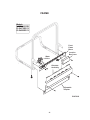
26
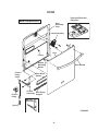
DOOR
Detergent/Rinse Aid
Dispenser
Model LEDB500FEE0
Door
Assembly
Liner
Latch Assembly
Door
Clamp
Handle
Mounting
Backer
Friction
Pulley
Cable
Friction
Pulley
Door Handle
Door Wiper
Gasket
LH Arm
Assembly Door Hinge
Support
RH Arm
Assembly
Spring
P30B0042
27
DOOR
Detergent/Rinse Aid
Dispenser
Models
PLD4375RFC0
PLD4555RFC0
Door
Assembly
Liner
Latch Assembly
Door
Clamp
Handle
Mounting
Backer
Friction
Pulley
Cable
Friction
Pulley
Door Handle
Door Wiper
Gasket
LH Arm
Assembly Door Hinge
Support
RH Arm
Assembly
Spring
P30B0044
28
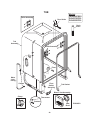
TUB
Roller Assembly
Door Strike
Models
LEDB500FEE0
PLD4375RFC0
PLD4555RFC0
Drain
Hose
Tub
Assembly
Roller Assembly
Float
Water
Inlet
Tubing
Clamps
Float
Switch
Assembly
Tub Gasket
Blower Vent Assembly
Clamp
Thermostat
DO
NO
Retainer
NO
SE
TR
RV
IC
EM
EA
OV
BLE
EC
O
PA
RT VER
S IN
SID
E
Vent
Bezel
29
P30U0023
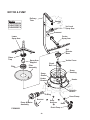
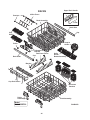
MOTOR & PUMP
Gasket
T
U
B
Models
LEDB500FEE0
PLD4375RFC0
PLD4555RFC0
Delivery
Tube
3rd Level
Spray Arm
Grommet
Center
Spray Arm
Lower
Spray Arm
Soil
Director
Base
Glass
Trap
Filter
Spray Arm
Support
Volute Cover
Check
Ball
Filter
Assembly
Sump
Housing
Sump
Gasket
Heater
Bracket
T
U
B
Heater
Turbidity
Sensor
O-Ring
Hose Clamp
Bracket
Pump & Motor
Assembly
Sump
Retainers
Drain Pump
P30M0036
30
Hose
FRAME
Models
LEDB500FEE0
PLD4375RFC0
PLD4555RFC0
Front
Frame
Brace
Junction
Box Cover
Water
Valve
Kickplate
Assembly
Adjustable
Toeplate
P30F0022
31
RACKS
Fence
Bracket
Handle Assembly
Upper
4 Wire Fence
Rack
Assembly
Lower
3 Wire
Fence
Slide Rack
Cap
Cup Shelf
Snap In
Holder
Roller
Adjustment
Bracket
Slide
Cap
Rack
Slide
Cup Shelf Fence
Knife
Fold Holder
Down Basket Assembly
Fence
Bracket
Cup Shelf Fence
Silverware
Baskets
Rear Roller
Assembly
Model
LEDB500FEE0
Rack Assembly
Front Roller
Assembly
P30R0105
32
RACKS
Bracket
Upper Rack Handle
Rear
4 Wire Fence
Rack Assembly
Rack
Slide
Front
3 Wire
Fence
Cap
Cup Shelf
Roller
Adjustment
Bracket
Utility
Basket
Rack Slide
Cap
Fold Down Fence
Bracket
Silverware Baskets
Model
PLD4375RFC0
Rack Assembly
Wheel & Bracket
Assembly
33
P30R0106
RACKS
Upper Rack Handle
Rear
4 Wire Fence
Bracket
Rack Assembly
Front
Rack Slide
Cap
Cup
Shelf
Snap-In
Holder
Roller
Adjustment
Bracket
Fold Down Fence
Cap
Rack Slide
Knife
Holder
Basket Assembly
Bracket
Cup Shelf Fence
Silverware
Baskets
Roller
Assembly
Rack Assembly
Model
PLD4555RFC0
P30R0076
34
Display Codes (LED)
Display Codes (Readout)
ER/CE....Configuration Error
ER/uo.....Vent will not close
ER/uF.....Fan not running
Thermistor
Fan speed
Rinse aid
P1
P3-6
ULTIMATE/MAXX
CYCLES
NORMAL WASH
CHINA/CRYSTAL
ECO WASH
GLASSES
SPEED WASH
RINSE ONLY
SENSING
LED
WASHING
SANITIZED
DRYING
CLEAN
TIME
IN
MINUTES
WASH 1
8 MIN.
RINSE 1
11 MIN.
RINSE 2
11 MIN.
RINSE 3
11 MIN.
WASH 2
32 MIN.
RINSE 4
11 MIN.
RINSE 5
11 MIN.
RINSE 6
15.5 MIN.
DRY *(HOT OR COOL)
22 MIN.
WATER VALVE
OUTPUTS
FAN/DAMPER
PUMP MOTOR
DRAIN MOTOR
HEATER
DISPENSERS
TURBIDITY SENSE
*Note: The Sahara/Maxx Dry will extend drying time by approximately 20 min.
WATER HEAT DELAY
WATER HEAT DELAY
35
W
W
NEUT W
P3-5
BK
P2-2
P2-1
P2-3
BK
R
BK
DOOR
L1 BK SWITCH
W
W
W
W
P1
HI-LIMIT
THERMOSTAT R
FLOAT
SWITCH PK
P3- 1
P6
DISPLAY
ELECTRONIC
CONTROL
BOARD
P2- 8
P3-7
P2- 7
BK
BK
P3-2
P3-8
Y
VIO
P3-4
BU
P32-9
P32-6
P2-11
P2-12
P2-13
P-5
USER INTERFACE SWITCH
Th
UF
RA
120VAC
60HZ
0 0
X 0
TURBIDITY SENSOR/
THERMISTOR
HEATER W
1
1
WATER VALVE
0
0
Uo
Tu
HS
RINSE AID
LEVEL SENSE
0 0 0 0 0 0
0 0 0 1 0 0
0 0 1 0 1 0
X - denotes selectable option
CLEAN LED stays on until door is opened or cycle is started.
0
0
Fan damper
Turbidity
Hall sensor
DRAIN MOTOR
0
0
0
1
1
1
HALL SENSOR
0
0
0
0
0
0
BK
R
BK-W
R-W
Y/BL
0
0
0
0
0
0
Display flashes when
Detection of failure
0
0
0
0
0
0
W
1
1
1
1
0
0
Device being monitored
1
1
1
1
0
0
PUMP MOTOR
0
0
0
0
0
0
1
1
FAN DRY UNIT
1
0
0
0
0
1
RINSE LED
0
0
1
1
1
1
FAN UNIT
DRAIN MOTOR
HEATER
DISPENSER
0
0
0
0
0
0
CLEAN LED
0
0
1
0
1
1
SANITIZED LED
1
1
0
0
0
0
DRYING LED
60
27
45
0.4
75
60
90
90
447
SENSING LED
WASHING LED
FILL/DISPENSER
FILL
WASH/HEAT
PAUSE
WASH/HEAT
WASH/HEAT/DISP.
DRAIN
DRY
TOTAL
Y-BK.............Yellow/Black
R-W..................Red/White
BK-W............. Black/White
R-Y..................Red/Yellow
VIO..........................Violet
Wiring Diagram
TOTAL TIME (SEC)
WATER VALVE
CIRCULATION MOTOR
STEP
1
2
3
4
5
6
7
8
BK.......................... Black
BU............................Blue
PK............................Pink
R...............................Red
R-BK...............Red/Black
W............................White
(Some models)
For controls
lock . . . . . . . . . . . Press and hold the RINSE ONLY or AIR DRY
pad for 3 seconds. To unlock, press and hold the
RINSE ONLY or AIR DRY pad for 3 seconds.
P3- 3
To cancel cycle
Press desired cycle and/or option pad. The indicator
lights will change. Press START/CANCEL within 15
seconds to begin cycle.
Press START/CANCEL. Dishwasher will drain for
90 seconds, then shut off.
P2- 4
P2- 5
P2- 6
Close and latch door. Press DELAY START pad to
select desired delay time.
To select a new
cycle or option
R
W
BK
To delay start
SENSING ---------------------- Turbidity sensor is checking the condition of the wash/rinse water.
No sensing for LIGHT WASH (UPPER RACK), LIGHT WASH (LOWER RACK) and CHINA/CRYSTAL.
WASHING ---------------------- Wash portion of cycle.
SANITIZED -------------------- The SANITIZED criteria has been met. Indicator light will switch off when door is opened.
DRYING ------------------------ Drying portion of cycle.
CLEAN ------------------------ Shows completion of cycle. Indicator light will switch off when door is opened.
OPTION LED's Flashing -- HI-TEMP WASH and NO HEAT DRY/POWER DRY OFF LED's flashing indicates power failure has
occurred. Press START/CANCEL pad and reselect desired options and cycle.
STATUS LED's Flashing -- The STATUS LED's that are lit when the door is opened will flash. Close door.
RINSE AGENT LOW ------- The liquid rinse agent is low. Light will switch off after 5 complete wash cycles or dispenser is filled.
DISPENSER
Close and latch door. Press START/CANCEL pad.
R-Y
To start
Exploded View of Wash System
Standard Dry Air Flow
When the control advances to the “dry” portion of
the cycle, a vent actuation solenoid is closed.
This opens the vent valve and starts the vent fan
both located in the top right rear corner of the tub.
The fan draws in the air from outside the tub,
forcing the hot, humid air down and out the
bottom of the outer door panel. This outside,
cooler, dryer air helps to speed evaporation of
water from the hot dishes. At the same time the
heating element is continually cycled on and off.
On some models the dry portion of the cycle can
be extended to improve drying performance.
Trouble Shooting Tips
Personal Injury Hazard
Always disconnect the dishwasher from the electrical power source before adjusting or
replacing components.
Symptom
Check the Following
Remedy
Dishwasher will not operate when
turned on.
1. Fuse (blown or tripped).
2. 120 VAC supply wiring connection
faulty.
3. Electronic control board defective.
4. No 12 VAC power to control.
5. Motor (inoperative).
6. Door switch (open contacts).
7. Door latch not making contact with
door switch.
8. Touch pad circuit defective.
9. No indicator lamps illuminate when
START or OPTIONS are pressed.
1. Replace fuse or reset breaker.
2. Repair or replace wire fasteners at
dishwasher junction box.
3. Replace control board.
4. Replace control board.
5. Replace motor/impeller assembly.
6. Replace latch assembly.
7. Replace latch assembly.
Motor hums but will not start or run.
1. Motor (bad bearings).
2. Motor stuck due to prolonged
non-use.
1. Replace motor assembly.
2. Rotate motor impeller.
Motor trips out on internal thermal
overload protector.
1. Improper voltage.
2. Motor windings shorted.
3. Glass or foreign items in pump.
1. Check voltage.
2. Replace motor/impeller assembly.
3. Clean and clear blockage.
Dishwasher runs but will not heat.
1.
2.
3.
4.
Heater element (open).
Electronic control board defective.
Wiring or terminal defective.
Hi-Limit thermostat defective.
1.
2.
3.
4.
Replace heater element.
Replace control board.
Repair or replace.
Replace thermostat.
Detergent cover will not latch or
open.
1.
2.
3.
4.
5.
Latch mechanism defective.
Electronic control board defective.
Wiring or terminal defective.
Broken spring(s).
Defective actuator.
1.
2.
3.
4.
5.
Replace dispenser.
Replace control board.
Repair or replace.
Replace dispenser.
Replace dispenser.
Dishwasher will not pump out.
1.
2.
3.
4.
5.
6.
Drain restricted.
Electronic control board defective.
Defective drain pump.
Blocked impeller.
Open windings.
Wiring or terminal defective.
1.
2.
3.
4.
5.
6.
Clear restrictions.
Replace control board.
Replace pump.
Check for blockage, clear.
Replace pump assembly.
Repair or replace.
Dishwasher will not fill with water.
1. Water supply turned off.
2. Defective water inlet fill valve.
3. Check fill valve screen for
obstructions.
4. Defective float switch.
5. Electronic control board defective.
6. Wiring or terminal defective.
7. Float stuck in “UP” position.
1. Turn water supply on.
2. Replace water inlet fill valve.
3. Disassemble and clean screen.
1. Drain hose (high) loop too low.
1. Repair to proper 32-inch minimum
height.
2. Install air gap at counter top.
Detergent and Rinse Aid Dispenser
The detergent and rinse aid dispenser is a one
piece component consisting of a molded
detergent cup and a built-in rinse aid dispenser.
The detergent cup has a spring loaded cover
and the rinse aid dispenser has a removable
cover.
Liquid rinse aid is added to the dispenser up to
the fill line indicator. The amount of rinse aid
released can be adjusted by turning the arrow
indicator from one, being the least amount, to
four, being the greatest amount.
To replace dispenser:
•
•
•
•
•
•
•
shut off electricity to dishwasher,
remove outer door panel assembly,
disconnect wiring to the actuator,
remove the six screws,
remove the dispenser,
replace and reinstall screws,
rewire actuator.
8. Replace console assembly.
9. Replace console assembly.
Tub and Door Seal
The door seal is pressed into the tub channel for
an interference fit. To install the seal, locate the
center mark on the seal back and press into
place. Next, install the bottom of the seal by
creating a short turn at the bottom of the tub
channel and ensuring the seal extends to the
locator ridge at the bottom of the tub. Then align
and gently press the seal into the channel in only
a few spots. Next, close and latch the door to
allow the gasket to seat properly into the channel.
Gasket Cross Section
Pump Assembly
The pump assembly is driven by a synchronous
motor. Rotation is in the counterclockwise
direction at 3600 RPM. The motor drives a pump
which supplies 100 percent filtered water at a
rate of approximately 12 GPM to one spray arm
at a time. The spray arm’s operation is alternated
by small “pauses” of the motor during the wash
cycle.
Draining is accomplished by using a small
separate synchronous drain pump mounted to
the side of the sump. The drain pump is
connected to the main pump by a small rubber
hose. The drain check valve is located at the
discharge end of the drain pump. The drain hose
Mounting
Rib
is attached by a worm gear clamp to the discharge
end of the drain pump.
The drain hose must have a loop at a minimum
height of 32 inches in order to insure proper
drainage.
The main pump can easily be removed by
disconnecting the upper spray arm supply tube
hose, the drain pump connector hose, the wiring
harness connections made at the circulation
motor, the water heat thermistor located on the
bottom of the pump and rotating the four sump
retainers toward the middle of the sump.
Tub
Interior
Dishwasher water siphons out.
Short Turn
2. Drain line connected to a floor drain
not vented.
Product Specifications
Electrical
Rating ................................... 120 Volts, 60Hz
Separate Circuit..15 amp min.- 20 amp max.
Motor (Amps) ........................................... 1.8
Heater Wattage ....................................... 900
Total Amps (load rated) ......................... 10.0
TempAssure .............................. 140°F ±5°F
(60°C±3°C) [with outer door in place]
TempBoost ............. 145°F ±5°F (63°C ±3°C)
Heated Wash/Heated Rinse
Sanitize .................. 150°F ±5°F (66°C ±3°C)
Hi-Limit Thermostat ................ 200°F (93°C)
Detergent left in dispenser.
Water Supply
Suggested minimum incoming water
temperature ............................. 120°F (49°C)
Pressure (PSI) min./max. ................... 20/120
Connection (NPT) ..................................... 3/8"
Consumption (Normal Cycle) .......................
............. 4.9 - 9.7 U.S. gal., 18.5 - 36.7 liters
Water valve flow rate (U.S. GPM) ........... .83
Water recirculation rate (U.S. GPM) ..............
.................................................... approx. 12
Water fill time ..................................... 87 sec.
1. Detergent allowed to stand too long in
dispenser.
2. Dispenser wet when detergent was
added.
3. Detergent cover held closed or blocked
by large dishes.
4. Improper incoming water
temperature to properly dissolve
detergent.
5. See "Detergent cover will not open."
4.
5.
6.
7.
Repair or replace.
Replace control board.
Repair or replace.
Clean float.
1. Instruct customer/user.
2. Instruct customer/user.
3. Instruct customer/user on proper
loading of dishes.
4. Incoming water temperature of
120°F is required to properly
dissolve dishwashing detergents.
020905
36