1
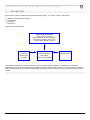
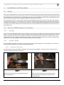
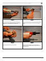
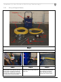
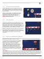
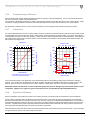
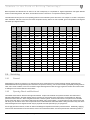
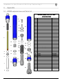
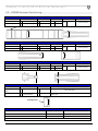
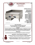
HDD60 Operation and Service Manual Copyright © Mincon 2010, All Rights Reserved. TABLE OF CONTENTS Table of Contents .......................................................................................... 2 1 Introduction ............................................................................................... 3 2 Installation and Operation ......................................................................... 4 2.1 Safety....................................................................................................................................... 4 2.2 Set up of HDD60 Hammer and Sonde ..................................................................................... 4 2.2.1 2.2.2 Storage .......................................................................................................................................................... 4 Setup of Sonde .............................................................................................................................................. 4 2.2.2.1 2.2.2.2 2.2.3 2.3 2.3.1 2.3.2 2.3.3 2.3.4 2.3.5 2.3.6 2.3.7 2.3.8 2.4 2.4.1 2.4.2 2.4.3 2.4.4 2.4.5 2.4.6 2.4.7 Installation of DCI Sonde.................................................................................................................................................. 4 Installation of Sub-Sight Sonde ........................................................................................................................................ 8 Installation of Bit............................................................................................................................................. 9 Setup and Operation of Support Station ................................................................................ 10 Set up of Support Station ............................................................................................................................. 11 Equipment Inspection Prior to Compressor Ignition .................................................................................... 13 Pressure Regulator Adjustment ................................................................................................................... 14 Oiler Adjustment .......................................................................................................................................... 14 Water Pump Adjustment and Operation ...................................................................................................... 14 Commissioning of Hammer ......................................................................................................................... 15 Lubrication ................................................................................................................................................... 15 Operation of Hammer .................................................................................................................................. 15 Servicing ................................................................................................................................ 17 General ........................................................................................................................................................ 17 Opening Chuck and Backhead .................................................................................................................... 17 Dismantling Hammer to Change Drill Bit ..................................................................................................... 18 Disassembly for Full Servicing of Hammer .................................................................................................. 18 Inspection ..................................................................................................................................................... 18 Checking Wear Limits .................................................................................................................................. 18 Reassembly ................................................................................................................................................. 18 3 Appendix ................................................................................................. 20 3.1 HDD60 exploded view and Parts List..................................................................................... 20 3.2 HDD60 Hammer Service Log ................................................................................................ 21 4 Warranty ................................................................................................. 22 Mincon – “Leaders in Rock Drilling Technology” Page 2 1 Introduction This document covers the HDD60 Horizontal Directional Drilling System. The system consists of the following: • • • • HDD60 Horizontal Directional Hammer Support Station Compressor Water supply The basic setup is shown below. Horizontal Directional Drill Including but not limited to: Astec DD4045, DD 6, DD8, AUDD9014 Ditch Witch JT4020 M1, 7020, JT100 Vermeer 36X50, 80X100, 100X120 Water Truck Support Pack Compressor Dust Control Sonde Cooling 2-4 Gal/Min Rock Drill Oil Injection Water injection Compressor to Drill adapter Minimum 275 PSI The Installation and Operation section will deal with setup of the system and basic operation. Following that we will deal with disassembly and servicing. When dealing with the HDD60 in the service section we will separate it into two parts: Firstly the Horizontal Directional Drilling hammer component that makes drilling possible and secondly the Sonde housing component that makes steering possible. Mincon – “Leaders in Rock Drilling Technology” Page 3 2 Installation and Operation 2.1 Safety Be sure to work safely at all times. Wear protective clothing and safety equipment and observe all safety regulations as prescribed by your employer, Government, or the site on which you work. Do not wear loose clothing that may get caught in rotating parts and cause serious personal injury. Remember that a “Horizontal Down-the-Hole” percussive hammer emits noise and you should therefore take every precaution to safeguard your hearing against damage by using proper ear protectors. Use eye protection at all times. Rock chips and dust which may be discharged from the face of the bit or bore hole at high velocities and can cause severe injury. Hammers can be heavy – Always use proper and approved lifting equipment and take every precaution to safeguard yourself against injury. Keep hands clear at all times – Beware of getting fingers trapped between the chuck and bit and do not use hands or feet to clear the top of the borehole at any time. Other safety advice is given throughout this document which you are advised to read. 2.2 Set up of HDD60 Hammer and Sonde 2.2.1 Storage If you intend to store the HDD60 Hammer we recommend that ½ pint (¼ litre) of good quality rock drill oil be poured into the hammer to protect it. To do this the hammer section should be unscrewed from the Bent Sub and then the oil should be poured into the top of the hammer and let flow down into the piston chamber of the hammer to coat the parts and protect them from rust and corrosion. Once completed the bent sub and the Sonde Housing can be reinstalled. Ensure that the thread protector and chuck cap are fitted to keep debris out and to prevent oil leakage. Store the hammer horizontally in a clean dry place. 2.2.2 Setup of Sonde When the HDD60 is supplied it will contain the necessary parts for the successful installation of a commercial Sonde. The two main types of Sonde are dealt with in this manual: DCI Sonde and Sub Sight. 2.2.2.1 Installation of DCI Sonde The following series of picture will detail the installation of a DCI Sonde into the HDD60. The same procedure should be used for servicing or changing the Sonde at a later date. STEP 1 Unscrew and remove Sonde Housing Backhead from the Sonde Housing Sleeve Mincon – “Leaders in Rock Drilling Technology” STEP 2 Insert and screw the Sonde Line Up Tool into the Sonde Carriage retrieval cap and pull out the complete Sonde Carriage assembly. Page 4 Step 3 Unscrew and remove the Sonde Carriage Locating Cap, Springs and the DCI Adapter from the Sonde Carriage (At Opposite end to the Sonde Carriage retrieval cap) Step 5 Insert and push the DCI Sonde into the tube. Mincon – “Leaders in Rock Drilling Technology” Step 4 Loosen and remove with the Torque Wrench the DCI Adaptor Locating cap from the tube. The correct end has locating dimple. Step 6 Fit the DCI Adaptor Locating cap onto the DCI Sonde ensuring the Locating cap’s intrical key is seated correctly in the Sonde Keyway. Page 5 Step 7 Push the Sonde in the rest of the way and screw the DCI Adaptor Locating Cap in and tighten snugly with the Torque wrench. Sonde Carriage Locating Cap Groove Step 8 Step 9 Insert first spring into the Sonde Carriage. Step 10 Insert the DCI Adaptor into the Sonde Carriage Insert the second spring in to the Sonde Carriage. DCI Adaptor Locating Dimple Step 11 Align the Sonde Carriage Locating Cap Groove with the DCI Adaptor Locking Dimple and push the cap on so that the hex socket of the Carriage Locating Cap fits over the DCI Adaptor and then screw the Carriage Locking Cap in place Step 12 Push the Sonde carriage into the Sonde Housing Sleeve with the Sonde Carriage Locating cap entering first. Mincon – “Leaders in Rock Drilling Technology” Step 13 Screw the Retrieval bar into the Sonde Carriage and push forward until it stops. Turn gently until you feel the Sonde Carriage go forward and the Sonde Carriage Locking Cap groove seats over the Sonde Carriage Locating pin (See Step 14 for details of the pin). Page 6 Sonde Carriage Locating Pin Step 14 Above picture shows the Sonde Carriage Locating Pin. The pin is in the Bent Sub set so that the Sonde will be aligned correctly in the twelve O’clock position. Mincon – “Leaders in Rock Drilling Technology” Step 15 Insert and screw the Sonde Housing Backhead in place. Page 7 2.2.2.2 Installation of Sub-Sight Sonde The procedure for installing a Sub-Sight Sonde is the same as the DCI Sonde except Step 3 through Step 7 are replaced with the following: Step 1 Step 2 Above picture shows the end of the Sub Sight Sonde that will receive the Sub Sight Locating adaptor. All screws to be inserted should have the threads coated with a thread lock compound. Step 4 Step 5 Fit the second half of the Sub Sight adaptor to the Sonde and tighten. Then fit the assembly locking screw as shown above. Fit the top section of the Sub Sight locating assembly and tighten. Mincon – “Leaders in Rock Drilling Technology” Step 3 Fit the first half of the Sub Sight adaptor to the Sonde and tighten. Step 6 Unscrew the other end off the Subsight and replace with the Adaptor end cap shown above. Once completed the Sonde assembly can be installed from Step 8 above. Page 8 2.2.3 Installation of Bit The following sequence of instructions is used to correctly fit the bit in the correct orientation for drilling. Step 1 Unscrew and remove the Chuck from the Hammer. Step 2 Remove Bit Retaining Ring from the hammer and screw the Chuck back in place. Step 3 Insert the bit into the Chuck so that the Bent Sub wear carbides are aligned in a straight line with the three bit wear carbides as illustrated above. Mincon – “Leaders in Rock Drilling Technology” Page 9 Step 4 Step 5 Unscrew the Chuck and Bit from the hammer making sure that the bit does not come out of the Chuck. Place the Bit Retaining Rings onto the bit, below the bearing surface secured by O Ring. Step 6 Screw the Chuck, Bit and Bit Retaining Rings in place. 2.3 Setup and Operation of Support Station Prior to operation the Support Station must be setup to ensure that correct and safe operation of the equipment is carried out. CAUTION – For safe working conditions during operation of the equipment it is essential to have received the appropriate training prior to starting up the equipment. Mincon – “Leaders in Rock Drilling Technology” Page 10 2.3.1 Set up of Support Station Support Station 30’ Air Hose 20’ Air Hose TRI-Lite Valve Controller 2” NPT Couplings Water Hose Whip Checks Step 1 Unpack Support Station and check to make sure all components are present. Step 2 Support Station comes delivered with whip checks in place on both the air intake and discharge lines. Enlarge loop on the other end of the whip check on the air intake valve end and loop over air hose and release. Step 3 Connect air hose to Support Station air intake valve. Mincon – “Leaders in Rock Drilling Technology” Step 4 When completed pull whip checks back so that they are as shown above. Above picture shows air discharge side of support station. Page 11 Step 5 Connect air hose to the compressor in the same manner. Connect other air hose to Support Station discharge line and to Drill also using the same procedure. Step 6 Hook TRI light controller connections to electric valve Step 7 Before Operation, check level of oil in the water pump fill cap with dip stick. Step 8 CAUTION: Always follow these instructions when filling tank with rock drill oil. 1. Turn compressor off and shut valve off at compressor. 2. Turn electric valve off make sure you see a red light on the Tri-Lite Controller and Red or Yellow indicator on the top of valve is pointing perpendicular to valve body. 3. Open vent valve (Labelled #1 Vent Valve above) lower right hand control knob, relieving air pressure inside of tank to atmospheric air pressure. 4. After air has bled out of tank, use hammer to hit four inch hammer fitting on top of tank counter clockwise to loosen, and then take off by hand. 5. Fill oil to top of tank, but not past fitting in the middle of the neck. 6. Refit Oil tank cap and tighten using a hammer. CAUTION: Always make sure 4” cap is tight on tank and vent valve is closed before starting compressor. Mincon – “Leaders in Rock Drilling Technology” Page 12 2.3.2 Equipment Inspection Prior to Compressor Ignition CAUTION: The following walk around check should be carried out prior to starting the compressor. Step Specific Equipment Required State 1 Hose connecting Drill to Support Station RED Air flow arrow goes to Drill. Hose connected to outlet valve. 2 Hose connecting compressor to Support Station Connected at electric inlet valve. 3 Inlet and Outlet Valve Connections Wing nuts tightened using hammer turning clockwise. 4 Inlet and outlet valves on Support Station Whip Checks Connected correctly as described in above sections. 5 Hose to compressor connection Wing nuts tightened using hammer turning clockwise. 6 Hose to compressor connection Whip Check Connected correctly as described in above sections. 7 Hose to Drill connection Wing nuts tightened using hammer turning clockwise. 8 Hose to Drill connection Whip Check Connected correctly as described in above sections. 9 4” Wing Nut on top of Rock Drill Oil Tank Tightened using hammer turning clockwise. 10 Rock Drill Oil Tank Vent Valve 11 Main Air Discharge valve (2” Valve to Drill) Open (Parallel to Valve Body) 12 Power Connections for Tri-Lite Controller Connected to 12V Battery – Black to NEGATIVE (-) and Red to POSITIVE (+) 13 Tri-Lite Controller Valve Operation Operating correctly – Red light means air off (Valve closed) Green light air on (Valve Open) 14 Tri-Lite Controller Valve Red light – air off (Valve closed) prior to starting compressor Mincon – “Leaders in Rock Drilling Technology” Complaint () Closed (knob pointing to up as in Photo) Page 13 2.3.3 Pressure Regulator Adjustment On a new support station, the pressure regulator needs to be set at 80 PSI. To adjust the pressure after the walk around inspection and the compressor is operational, turn the Air Discharge Valve (Valve to Drill - 2” ball valve) off, Turn electric valve on (green light on) this will pressurize the system. Adjust the regulator clockwise to turn air pressure up and counter clockwise to turn pressure down. Set pressure gauge to 80 PSI. After adjustment turn electric valve off (red light) and turn Air Discharge Valve on, handle parallel to the valve body. CAUTION; Operating at higher pressures may cause motor to develop an air lock and stop operating. 2.3.4 Oiler Adjustment The amount of oil is dependent on where the needle valve is set. The needle valve is located on the far left as shown here. Turning the valve counter clockwise provides more oil and clockwise gives less oil. A good starting point is to close the valve fully and then turn one and a half revolutions to the counter clockwise. The two valves located on the control panel (see photo) are how you turn the oiler on and off. During drilling the two valves should be ON. When not drilling turn valves OFF. CAUTION: At the end of the day turn the valves off or you will be wasting oil. The oiler will continue to oil whether compressor is on or off. It is recommended that on a new system, until the operator is familiar with the system that after each rod is drilled down ¼ cup or two ounces of rock drill oil be poured in each rod, especially if a new hammer is being commissioned. 2.3.5 Water Pump Adjustment and Operation Always prime water hose before hooking the cam lock to the pump. It is essential to have the water tank above the support station to maintain sufficient head pressure for the pump to operate. The amount of water being introduced into the drilling operation is controlled by turning the knob labelled water on front panel to desired amount of flow. The amount of water required to maintain a clean hole will be dependent on the drilling conditions. Approximately 3-4 gallons per minute will suffice however in softer rock conditions more water may be required and significantly harder conditions will require less. Once the optimal water injection is set the water will turn off when the operator turns off the main air supply to the drill and conversely turn on when the main air supply is turned on. It is best to adjust the water while drilling as conditions can change throughout the bore hole. CAUTION: Never turn the water pump on with the main discharge valve (2” Ball valve to Drill) on the support station closed. The water should always have a path out and through the drill string. Always use clean water. Bentonite should not be used as this will clog up the hammer requiring a complete overhaul to return the hammer to an operable condition. A good mixture of polymer and Condet is acceptable if drilling in clay. Check the in-line filter on the pump periodically for debris. In colder conditions antifreeze the pump and drain the 40 foot water hose and clean and empty the in-line filter to protect from freezing while not operating the drill. Mincon – “Leaders in Rock Drilling Technology” Page 14 2.3.6 Commissioning of Hammer Coat the drill bit shank and the hammer threads with grease for protection and easier dismantling. Prior to use, lubricate the hammer with ½ pint (¼ litre) of rock drill oil as described above. Fit the hammer to the drilling rig ensuring no debris or dirt enters the hammer from the site, dirty tubes or from unclean air lines. Make sure that the coupling threads from the drill are of the same specification to that of the hammer and they are in good condition. Run the hammer at half the air flow for a few minutes to allow the oil to flow through and for internal components to settle in. 2.3.7 Lubrication It is vital for HDD hammers to receive a constant supply of proper rock drill oil to protect the internal components and to provide a good air seal between the piston and the inner cylinder, and the piston and the wear sleeve for efficient drilling. The correct consumption of oil is dependent upon the air volume and conditions. Please refer to the lubrication graph below for recommendations. When drilling in wet conditions the normal amount should be doubled. There should be visual evidence of oil around the drill bit shank and within the tube joints when changing tubes. Litres/Hour 1 1.5 2.0 2.5 34.5 120 48.9 1250 35.0 100 37.8 1000 28.0 750 21.0 500 14.0 250 7.0 Ambient Temperature ºF 42.0 80 26.7 ISO320 60 15.6 40 4.4 20 -6.7 ISO150 0 1 2 3 4 5 US Pints/Hour In wet drilling (above 2gpm/8 lpm) the oil consumption should be doubled Ambient Temperature ºC 1500 Air Volume – M3/MIN Air Volume - CFM 0.5 Pressure - Bar 6.9 13.8 20.7 27.6 -17.8 ISO46 -20 -28.9 100 200 300 400 500 Pressure - PSI The recommended grade of oil is dependent on the ambient temperature in which drilling is taking place as well as the operating pressure. As a rule of thumb, ISO320 grade rock drill oil should be used whenever possible as the hammer is a high frequency tool, however, where the pump cannot pump the oil in colder conditions, a lower grade of oil can be used as per the graph above. Remember: Insufficient lubrication or incorrect lubrication grades may result in damage being caused to the hammer and its components. Hydraulic oils, engine oils, gear oils and diesel are not recommended for lubricating HDD hammers. 2.3.8 Operation of Hammer Be sure to familiarize yourself with the controls of the machine and work in accordance with the manufacturers recommendations. The percussive mechanism begins to operate as the air supply is turned on and when the drill bit is pushed firmly into the hammer. Excessive thrust pressures are not needed to make it work. The thrust controls on the drill should be adjusted to the correct pressure and should be readjusted to take account of the weight of any extra tubes added so that the thrust pressure remains constant and not excessive. Insufficient thrust pressure will make the hammer drill erratically and less efficiently and cause premature wear to the bit and chuck splines with likely damage to the hammer components and threads. When the hammer is lifted from the rock face, the drill bit extends from the chuck and the percussive action ceases. Extra air will pass through the hammer, which can be used to flush the hole clean. Mincon – “Leaders in Rock Drilling Technology” Page 15 Rotation speeds should not be too high and should be selected to suit drilling conditions and drill bit diameters. High rotation speeds do not provide fast drilling and can cause premature wear of drill bits, hammers and tubes. Too slow a rotation speed can cause binding in the borehole and damage to drill bit inserts. The controls of the drill should be adjusted in order to provide the largest drill chip size with the smoothest rotation and feed characteristics. Recommended rotation speeds would normally vary between 25 – 35 R.P.M. for most applications. Where big diameter drill bits are used or when drilling in hard abrasive rocks, slower rotation speeds are recommended. Conversely, in soft, non-abrasive rock a slightly faster rotation speed may be selected to produce more satisfactory results. Some ground conditions may cause binding within the hole, with the added risk of the hammer and drill string becoming jammed. Any excessive pullback forces or high rotation speeds used in an attempt to recover the drill string may generate heat zones around the hammer, which may alter the metallurgy of the components to cause damage and ultimate failure. You are strongly advised not to pour diesel into the hammer as this may create an internal combustive effect and will damage the hammer and its components. Any heat induced failures are not covered by our terms of warranty. Before adding a drill rod make sure that the threads are clean and well greased and that there are no contaminants likely to enter the hammer to cause damage and early wear. Proper drill guides and break out systems must be used which suit the diameter of the hammer. All tools and spanners used for the drill bit and break out flats must fit properly. Make certain that the hammer is stationary when applying spanner or breakout tools. Do not rotate the hammer with a spanner attached to the drill string unless it is safely captivated within the breakout clamp. The Air Consumption of the hammer is as per the chart below. The chart represents operating pressure and equivalent air consumption at sea level with an ambient temperature of 68°F (20°C). Mincon – “Leaders in Rock Drilling Technology” Page 16 Both temperature and altitude have an effect on air and consequently on compressed air. Higher temperatures and higher altitudes result in air becoming thinner, less dense, and the effect of this is a reduction in a compressor’s delivery pressure. The table below shows just how much operating pressure can be affected by these two factors. For example, if we take a compressor which will deliver 1000 cfm at sea level, this same compressor will only deliver 745 cfm at 9,000ft, given a temperature of 40 degrees Fahrenheit (4.4 degrees Celsius). 2.4 2.4.1 Sea Level 1000ft 3000ft 5000ft 7000ft 9000ft 11000ft 13000ft 15000ft Sea Level 305m 915m 1524m 2134m 2744m 3354m 3963m 4573m -40 0.805 0.835 0.898 0.968 1.043 1.127 1.217 1.317 1.426 -30 -34.4 0.824 0.855 0.920 0.991 1.068 1.154 1.246 1.349 1.460 -20 -28.9 0.844 0.875 0.941 1.014 1.092 1.180 1.275 1.380 1.494 -10 -23.3 0.863 0.895 0.962 1.037 1.117 1.207 1.304 1.411 1.528 °F °C -40 0 -17.8 0.882 0.915 0.984 1.060 1.142 1.234 1.333 1.443 1.562 10 -12.2 0.901 0.935 1.005 1.083 1.167 1.261 1.362 1.474 1.596 20 -6.7 0.920 0.954 1.026 1.106 1.192 1.288 1.391 1.506 1.630 30 -1.1 0.939 0.974 1.048 1.129 1.217 1.315 1.420 1.537 1.664 40 4.4 0.959 0.994 1.069 1.152 1.241 1.341 1.449 1.568 1.698 50 10 0.978 1.014 1.091 1.175 1.266 1.368 1.478 1.600 1.732 60 15.6 0.997 1.034 1.112 1.198 1.291 1.395 1.507 1.631 1.766 70 21.1 1.016 1.054 1.133 1.221 1.316 1.422 1.536 1.662 1.800 80 26.7 1.035 1.074 1.155 1.244 1.341 1.449 1.565 1.694 1.834 90 32.2 1.055 1.094 1.176 1.267 1.365 1.475 1.594 1.725 1.868 100 37.8 1.074 1.114 1.198 1.290 1.390 1.502 1.623 1.756 1.902 110 43.3 1.093 1.133 1.219 1.313 1.415 1.529 1.652 1.783 1.936 120 48.9 1.112 1.153 1.240 1.336 1.440 1.556 1.681 1.819 1.970 Servicing General Dismantling the Hammer for servicing or to change the bit can be made easier if the chuck threads are regularly greased and the backhead threads are well greased any time the hammer is opened for servicing. We recommend that a good quality thread grease be used, and in acidic conditions, we do not recommend copper based greases as this can trigger a galvanic reaction with corrosive effect to damage the root of the threads and cause failure. 2.4.2 Opening Chuck and Backhead The threads used in Mincon Hammers are right hand threads. Proper tools and break-out systems should be used at all times to dismantle HDD hammers, otherwise damage may be caused to the components which could result in eventual failure or affect the performance of the Hammer. When using Petol wrenches or similar systems, ensure that the wrench is not placed on the threaded section of the wear sleeve. Petol wrench jaws should be carbide, and in good condition. It is good practice to keep a spare set of jaws with the rig. Do not strike or hit the outer components as this could weaken the heat treated steels. Hitting the hammer may also cause hard metal fragments to be chipped off which may be projected and cause personal injury or eyesight loss. Do not apply heat to the hammer, as this can alter the metallurgical composition and result in premature failure. Additionally, applying heat can also cause distortion to the wear sleeve, which in turn would lead to failure. Do not trap the hammer under drill rig tracks or Mincon – “Leaders in Rock Drilling Technology” Page 17 vehicle wheels which could cause bending and distortion of the hammer body. Failures caused by these actions cannot be supported by warranty. Take care when dismantling the hammer to make sure that parts and drill bits do not become detached and cause damage or personal injury. 2.4.3 Dismantling Hammer to Change Drill Bit When possible, dismantling the Hammer to change the drill bit is preferably best done in a workshop environment to avoid the risk of injury and for cleanliness. Be careful to ensure that the drill bit and chuck are fully supported together so that there is no risk of them becoming detached and causing injury. This can occur if the O Ring on the bit retaining rings is missing or damaged. Before fitting a new drill bit visually inspect the splines of the chuck and the piston striking face to ensure that both are not damaged in any way. Fit new bit as described in section 2.2.3 above. 2.4.4 Disassembly for Full Servicing of Hammer Breakout the Chuck and Backhead as described previously. Unscrew chuck and remove bit and bit retaining rings. Unscrew the backhead and check to see if the check valve and spring are operating correctly, and then remove them. Mark one end to identify either the chuck or backhead end for reassembly latter. Stand hammer up with the chuck end uppermost. Using a mild steel bar, tap the strike face of the piston to remove the air distributor and inner cylinder. The steel make-up ring and lock ring should fall out during this process, if so remove them and continue until the top of the air distributor is at the top of the wear sleeve. The hammer can now be placed flat on the ground or put up onto a suitable vice, and using the mild steel bar, hit the piston strike face from the chuck end, to completely remove the air distributor, inner cylinder and piston. Stand the wear sleeve up with the chuck end on the ground. Invert the piston and drop into the wear sleeve so that it is upside down. Take care to ensure that fingers do not get caught between the piston and wear sleeve. Again stand the hammer up with the backhead end uppermost, and tap the piston strike face with the mild steel bar to remove the aligner. A number of blows may be necessary as the aligner and wear sleeve are an interference fit. The piston retaining ring will come out with the aligner. 2.4.5 Inspection Prior to inspection, thoroughly clean all parts using a suitable cleaning agent. Diesel is not recommended for cleaning as it can cause erosion to components, and damage to health. All parts should be visually inspected for any signs of damage, wear or cracking. The inner cylinder, wear sleeve and lock rings can be checked for unseen cracking by suspending them and lightly tapping with a screw driver. If they emit a ringing tone then they should be sound. However, a dull flat tone if emitted may indicate cracking, and the part should be replaced. Take particular care to check the internal bore of the wearsleeve for pick-up marks and galling. If these are present, the barrel of the wear sleeve should be honed out, using a hand hone to remove them. Inspect surface of the piston for pick-up marks and galling (usually caused through poor lubrication or the presence of contaminants) and smooth out with emery paper or a hand held grit stone. Where galling of the piston has occurred, substantial heat has been generated and quite often, micro cracking has occurred on the piston. In these cases, the piston should be replaced if there is evidence of such cracking. Check the strike face of the piston for cracking or damage. 2.4.6 Checking Wear Limits The performance of the hammer is dependent on the amount of wear the critical components have. These should be measured and recorded in the Service log in the appendix. The service log gives the location of where measurements should be made. Depending on how many parts need to be replaced, it may be economical to replace the hammer all together. 2.4.7 Reassembly The hammer can be reassembled in the following manner, referring to the exploded view of the hammer in the appendix. Ensure all components are liberally coated with good quality rock drill oil and threads with thread grease. After identifying which end will be the chuck end, fit the piston retaining ring over the aligner. Stand the wear sleeve up with the chuck end to the top, and push the aligner in as far as it will go by hand. Using a steel dolly that fits into the wear sleeve and over the aligner, Mincon – “Leaders in Rock Drilling Technology” Page 18 hit the aligner into place with a sledgehammer. Place the bit retaining rings in on top of the aligner and screw the chuck in place. If the chuck does not close up fully, the aligner is not in fully. Turn wear sleeve over with the chuck on the floor, and drop the piston in with the strike face in first. Again ensure that fingers do not get caught between the wear sleeve and the piston. Place the three piece seating ring on the inner cylinder and secure in place with the seating ring O Ring. Insert The Air distributor into the inner cylinder at the seating ring end and using a soft headed mallet, tap it into place so that it seats up against the top of the inner cylinder. Place the inner cylinder assembly into the wear sleeve, and tap down with a soft headed mallet. When beginning to hit the assembly, ensure that it goes in square. Using a steel dolly, on top of the air distributor and inside the wear sleeve, drive the assembly into place with a sledgehammer. Place the lock ring in on top of the air distributor and then the Steel Makeup Ring on top of that. Insert the spring and check valve in place and finally screw the backhead in place. With the backhead in place, there should be a small gap between the backhead and the wearsleeve. This gap should be between 0.015” and 0.030”, and can be measured using a feeler gauge. If the gap is less than the minimum, then the lock ring will need to be replaced. Protect the hammer as earlier described by internal lubrication. Mincon – “Leaders in Rock Drilling Technology” Page 19 3 Appendix 3.1 HDD60 exploded view and Parts List MINCON HDD60 PARTS LIST AND SPECIFICATIONS 1 Item 17 16 18 2 27 9 19 20 21 3 22 10 23 11 24 28 4 12 5 13 25 31 6 32 14 15 26 7 33 Part no. MHD401AS01 SONDE HOUSING ASSEMBLY MHS401AS01 1 SONDE HOUSING BACKHEAD MHS401BH02 2 SONDE SPACER MHS402SS01 3 SONDE CARRIAGE MN585 4 O-RING MHS421OR01 5 DIVERTER MHS405DV01 6 O-RING MHS421OR01 7 SEALING SLEEVE MHS406SL01 8 O-RING MHS421OR01 9 SONDE HOUSING SLEEVE MHS404SH01 10 O-RING MHS421OR01 11 CARRIAGE GUIDE MHS407CG01 12 SONDE HOUSING SEATING RING MHS503SR01 13 O-RING MHS421OR01 14 LOCATING PIN MHS408LP01 15 BENT SUB MHD401BH02 16 CHECK VALVE MB502CV01 17 CHOKE MB506CH01 CHOKE 1/8 (3.2mm) MB506CH02 29 30 Description MINCON HDD60 HAMMER CHOKE 3/16 (4.8mm) MB506CH03 18 SPRING MD603SP01 19 STEEL MAKE UP RING MD404SM01 20 LOCK RING MD405LR01 21 AIR DISTRIBUTOR MD407DR03 22 O-RING MD421OR01 23 O-RING MD422OR01 24 SEATING RING MD409SR01 25 INNER CYLINDER MD408IC02 26 PISTON MD410PN04 27 WEAR SLEEVE MHD411WS02 28 PISTON RETAINING RING MD412PR01 29 O RING MD621OR01 30 ALIGNER MHD413BB01 31 BIT RETAINING RING MHD413BR01 32 CHUCK MHD414CK01 33 BIT 8 Mincon – “Leaders in Rock Drilling Technology” Page 20 3.2 HDD60 Hammer Service Log WEARSLEEVE / PISTON CLEARANCE Part New Dimension As Measured Wear Wearsleeve A 3.930” (99.84mm) C C-A Piston OD B 3.925” (99.70mm) D B-D Actual Clearance Discard Clearance ≥ 0.010” (0.25mm) C-D Chuck end D C INNER CYLINDER / PISTON CLEARANCE Part New Dimension As Measured Wear Cylinder ID A 3.386” (86.00mm) C C-A Piston OD B 3.381” (85.89mm) D B-D Actual Clearance ≥ 0.010” (0.25mm) C-D D Discard Clearance C DISTRIBUTOR PROBE / PISTON ID CLEARANCE Part New Dimension As Measured Wear Distributor Probe OD A 1.248” (31.70mm) C C-A Piston ID B 1.256” (31.90mm) D B-D C Actual Clearance Discard Clearance ≥ 0.010” (0.25mm) C-D D ALIGNER / BIT BEARING CLEARANCE Part Aligner ID (Unscalloped End) Bit Bearing Surface OD New Dimension A 3.018” (76.65mm) As Measured Replace dimension B 3.627” (92.13mm) Note: The head of the bit should wear out before the bearing surface does 3.006±0.002” (76.35±0.05mm) Scalloped end C EXTERNAL WEAR Description Wear Limit Wearsleeve Reverse Dimension: 4.570” (116.0mm) Wearsleeve Discard Dimension: 4.400” (112.0mm) As Measured Note: Chuck should be replaced when wear transfers to wearsleeve. Mincon – “Leaders in Rock Drilling Technology” Page 21 4 Warranty Mincon Hardrock Directional Drilling Hammers Warranty, January 2005 Mincon warrants that the Mincon Hardrock Directional Drilling Systems and spare parts therefore, manufactured by Mincon and delivered to the initial user to be free of defects in materials or workmanship for a period of 3 months after initial operation or 6 months from the date of shipment to the initial user, whichever occurs first. Mincon may elect to repair the defective part or issue full or partial credit towards the purchase of a new part. The extent of credit issued will be determined on a pro-rata basis bearing in mind the service life of the defective part against the normal service life of that part. The part will be replaced or repaired without charge to the initial user at the place of business of an authorized Mincon distributor during normal working hours. The user must present proof of purchase at the time of exercising the warranty. The warranty applies only to failures resulting from defects in the material or workmanship and does not apply to failures occurring as a result of abuse, misuse, corrosion, erosion, negligent repairs and normal wear and tear. Failure to follow recommended operating and maintenance procedures which result in component failure will not be considered for warranty. This warranty is in lieu of all other warranties, other than title, expressed or implied. Limitation of Liability. Mincon will not accept any remedies to the user other than those set out under the provisions of warranty above. The total liability of Mincon or its distributors with respect to the sale of DTH Hammers or spare parts therefore, whether based on contract, negligence, warranty, indemnity or otherwise shall not exceed the purchase price of the product upon which such liability is based. Mincon and its distributors shall in no event be liable to any party relating to this sale for any consequential, indirect, special or punitive damages arising out of this sale or any breach thereof, or any defects in or failure of or malfunction of the Mincon DTH Hammer or spare parts. Warranty will be voided where: • • • • • There is evidence of damage resulting from insufficient or incorrect lubrication. There is evidence of misuse through the application of heat, welding or of being struck. There is evidence of distortion or bending however caused. There is damage caused as a result of using incorrect servicing tools or procedures. If it is evident that the hammer or its components have achieved a reasonable proportion of their anticipated life. Mincon – “Leaders in Rock Drilling Technology” Page 22