1
IMPORTANT SAFETY NOTICES
PREVENTION OF PHYSICAL INJURY
1. Before disassembling or assembling any parts of the copier, make sure
that the power cord is unplugged.
2. The wall outlet should be near the copier and easily accessible.
3. If any adjustment or operation check has to be made with exterior covers
off or open while the main switch is turned on, keep hands away from
electrified or mechanically driven components.
4. The inside and the metal parts of the fusing unit become extremely hot
while the copier is operating. Be careful to avoid touching those
components with your bare hands.
HEALTH SAFETY CONDITIONS
1. Toner and developer are non-toxic, but if you get either of them in your
eyes by accident, it may cause temporary eye discomfort. Try to remove
with eye drops or flush with water as first aid. If unsuccessful, get medical
attention.
OBSERVANCE OF ELECTRICAL SAFETY STANDARDS
1. The copier must be maintained by a customer service representative who
has completed the training course on the model.
SAFETY AND ECOLOGICAL NOTES FOR DISPOSAL
1. Do not incinerate toner cartridges or used toner. Toner dust may ignite
suddenly when exposed to open flame.
2. Dispose of imaging units in accordance with local regulations. (These are
non-toxic supplies.)
3. Dispose of replaced parts in accordance with local regulations.
SECTION 1
OVERALL
MACHINE INFORMATION
SPECIFICATIONS
Overall
Information
4 July 1996
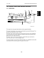
1. SPECIFICATIONS
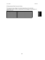
Configuration:
Desk Top
Copy Process:
Dry electrostatic transfer system
Originals:
Sheet/Book
Original Size:
Maximum: A4/8.5" x 14" (A183 copier)
B4/10" x 14" (A184 copier)
Copy Paper Size:
Paper tray feed:
A4, 8.5" x 11", 8.5" x 13", 8.5" x 14"
Bypass feed:
Maximum: A4/8.5" x 14"
Minimum: A5/5.5" x 8.5"
Copy Paper Weight:
Paper tray feed: 64 to 86 g/m2, 17 to 23 lb
Bypass feed: 60 to 105 g/m2, 16 to 27 lb
Reproduction Ratios
(A184 model only):
Enlargement
Full Size
Reduction
Metric Version
141%
122%
100%
93%
82%
71%
Inch Version
129%
100%
93%
85%
78%
Zoom (A184 model only):
From 70% to 141% in 1% steps
Copying Speed:
12 copies/minute (A4/8.5" x 11")
Warm-up Time:
Less than 30 seconds (at 23°C)
First Copy Time:
Less than 9 seconds (A4/8.5" x 11")
Copy Number Input:
Up/Down key, 1 to 50
Manual Image Density
Selection:
4 steps; can also be set to 5 steps
Automatic Reset:
1 minute standard setting; can also be set to
3 minutes or no auto reset
Paper Capacity:
Paper Tray:
250 sheets (A4/8.5" x 11", 80 g/m2/20 lb)
100 sheets (8.5" x 14", 80 g/m2/20 lb)
Bypass feed entrance: 1 sheet
Toner Replenishment:
Bottle exchange (91 g/bottle)
1-1
SPECIFICATIONS
4 July 1996
Copy Tray Capacity:
A4/8.5" x 11"
8.5" x 14"
OHP
Power Source:
Power Consumption:
Copy tray in the
open position
50 sheets
50 sheets
1 sheet
120 V/60 Hz:
More than 10 A (for North America)
220 ~ 240 V/50 Hz:
More than 6 A (for Europe)
220 V/50 Hz:
More than 6 A (for Asia)
220 V/60 Hz:
More than 6 A (for Middle East/Asia)
110 V/60 Hz:
More than 10 A (for Taiwan)
127 V/60 Hz:
More than 10 A (for Middle East)
Maximum
Copy cycle condition
Warm-up condiiton
Stand-by condition
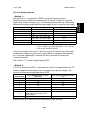
Dimensions:
Width
400 mm
(15.8")
Copier
Noise Emissions:
Copy tray in the
closed position
20 sheets
10 sheets
—
0.9 kW
0.5 kW
0.6 kW
0.1 kW
Depth
550 mm
(21.7")
Height
220 mm
(8.7")
Sound pressure level (the measurements are
made according to ISO 7779 at the operator
position.)
Less than 55 dB
Sound power level (the measurements are made
according to ISO 7779)
Stand-by condition
Copy cycle condition
Weight:
Less than 18 kg, 39.7 Ib
1-2
Less than 40 dB
Less than 63 dB
SPECIFICATIONS
Overall
Information
4 July 1996
MEMO
1-3
COPY PROCESS AROUND THE DRUM
4 July 1996
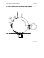
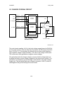
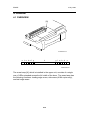
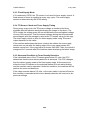
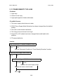
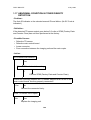
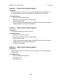
2. COPY PROCESS AROUND THE DRUM
2
3
1
7
4
6
5
A184V501.wmf
1-4
COPY PROCESS AROUND THE DRUM
1. DRUM CHARGE
In the dark, the charge corona unit gives a uniform negative charge to the
organic photoconductive (OPC) drum. The charge remains on the surface
of the drum because the OPC drum has a high electrical resistance in the
dark.
2. EXPOSURE
An image of the original is reflected to the drum surface via the optics
assembly. The charge on the drum surface is dissipated in direct
proportion to the intensity of the reflected light, thus producing an
electrical latent image on the drum surface.
3. ERASE
The erase lamp illuminates the area of the charged drum surface that will
not be used for the copy image. The resistance of the drum in the
illuminated areas drops and the charge on those areas dissipates.
4. DEVELOPMENT
Positively charged toner is attached to the negatively charged areas of
the drum, thus developing the latent image. (The positive triboelectric
charge is caused by friction between the carrier and toner particles.)
5. IMAGE TRANSFER
Paper is fed to the drum surface at the proper time so as to align the copy
paper and the developed image on the drum surface. Then, a strong
negative charge is applied to the back side of the copy paper, producing
an electrical force which pulls the toner particles from the drum surface to
the copy paper. At the same time, the copy paper is electrically attracted
to the drum surface.
6. CLEANING
The cleaning blade scrapes the toner off the drum. The collected toner is
recycled.
7. QUENCHING
Light from the quenching lamp electrically neutralizes the drum surface.
1-5
Overall
Information
4 July 1996
MECHANICAL COMPONENT LAYOUT
4 July 1996
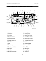
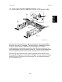
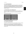
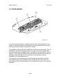
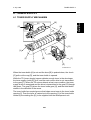
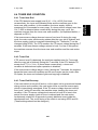
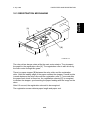
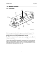
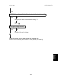
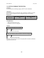
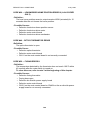
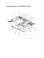
3. MECHANICAL COMPONENT LAYOUT
1
2
3
4
5
6
7
8
9
10
24
11
23
12
22
13
21
20
19
18
17
16
15
14
A184V500.wmf
1. 2nd Mirror
13. Relay Rollers
2. 1st Mirror
14. Paper Feed Roller
3. Exposure Lamp
15. Toner Bottle Holder
4. Quenching Lamp
16. Registration Rollers
5. Charge Corona Unit
17. Transfer Corona Unit
6. 6th Mirror
18. Drum
7. Lens
19. Cleaning Blade
8. Erase Lamp
20. Pressure Roller
9. Development Roller
21. Hot Roller
10. 4th Mirror
22. Exit Rollers
11. 5th Mirror
23. Copy Tray
12. By-pass Feed Table
24. 3rd Mirror
1-6
ELECTRICAL COMPONENT DESCRIPTIONS
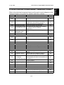
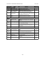
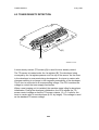
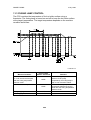
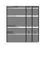
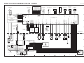
4. ELECTRICAL COMPONENT DESCRIPTIONS
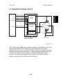
Refer to the electrical component layout and the point-to-point diagram on the
waterproof paper in the pocket for symbols and index numbers.
Symbol
Motors
M1
M2
M3
M4
M5
Name
Function
Main Motor
Drives all the main unit components except
for the optics unit and fans.
Exhaust Fan Motor
Removes heat from around the fusing unit
and blows the ozone built up around the
charge corona unit to the ozone filter.
Scanner Drive Motor Drives the scanners (1st and 2nd).
Lens and Mirror Motor Moves the lens and 4th/5th mirror positions
(A184 machines only) in accordance with the selected
magnification.
Optics Cooling Fan
Prevents build-up of hot air in the optics
Motor (220 ~ 240 V
cavity.
machines only)
Index No.
23
6
10
11
18
Clutches
CL1
CL2
Toner Supply Clutch
Paper Feed Clutch
Switches
SW1
Main Switch
SW2
Interlock Switch
Transfers main motor drive to the toner bottle
gear.
Transfers main motor drive to the paper feed
roller.
Supplies power to the copier.
Cuts all power when the upper unit is opened.
25
24
28
29
Sensors
S1
S2
S3
S4
S5
S6
ADS Sensor
Detects the background density of the
original.
Registration Sensor
Detects paper end conditions. Checks if
paper is set on the by-pass feed table.
Lens and Mirror
Informs the CPU when the lens and 4th/5th
H. P. Sensor
mirror assembly are at the home position (full
(A184 machines only) size position).
Scanner H. P. Sensor Informs the CPU when the 1st scanner is at
the home position.
Toner Density (TD)
Detects the ratio of toner to carrier in the
Sensor
developer.
Exit Sensor
Detects misfeeds.
15
26
8
2
14
30
Solenoid
SOL 1
Registration Solenoid Releases the stopper, synchronizing the
paper-feed timing with the original scan.
1-7
27
Overall
Information
4 July 1996
ELECTRICAL COMPONENT DESCRIPTIONS
Symbol
Name
Printed Circuit Boards
PCB1 Main Control Board
PCB2 Scanner Drive Board
High Voltage Supply
PCB3
Board - CT/B/G
AC Drive / DC Power
PCB4 Supply Board
PCB5
Operation Panel
Board
4 July 1996
Function
Index No.
Controls all copier functions.
Controls the scanner drive motor.
Provides high voltage for the charge corona,
transfer corona and development bias.
Drives the exposure lamp, fusing lamp and
main motor. Rectifies 30 Vac and 8 Vac input
and outputs 5 Vdc and 24 Vdc.
Informs the CPU of the selected modes and
displays the situation on the panel.
5
9
7
19
13
Lamps
L1
L2
L3
L4
Exposure Lamp
Applies high intensity light to the original for
exposure.
Fusing Lamp
Provides heat to the hot roller.
Quenching Lamp (QL) Neutralizes any charge remaining on the
drum surface after cleaning.
Erase Lamp
Discharges the drum outside of the image
area. (Provides leading/trailing edge and
side erases.)
1
22
17
16
Others
CO
TH1
TH2
TF1
TF2
TR
Total Counter (except Keeps track of the total number of copies
for -17 machines)
made.
Optics Thermistor
Monitors the temperature around the
exposure lamp for overheat protection.
Fusing Thermistor
Monitors the fusing temperature.
Exposure Lamp
Provide back-up overheat protection around
Thermofuse
the exposure lamp.
Fusing Thermofuse
Provide back-up overheat protection in the
fusing unit.
Transformer
Steps down the wall voltage to 30 Vac and 8
Vac.
1-8
12
3
21
4
20
31
SECTION 2
DETAILED DESCRIPTIONS
4 July 1996
DRUM
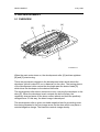
1. DRUM
The OPC (Organic Photoconductor) Drum used in this copier is small in
diameter (30 mm), ensuring good paper separation. An OPC drum has the
characteristics of:
1. Being able to accept a high negative electrical charge in the dark.
(The electrical resistance of a photoconductor is high in the absence of
light.)
2. Dissipating the electrical charge when exposed to light.
(Exposure to light greatly increases the conductivity of a photoconductor.)
3. Dissipating an amount of charge in direct proportion to the intensity of the
light. That is, where stronger light is directed to the photoconductor
surface, a smaller voltage remains on the drum.
4. Being less sensitive to changes in temperature (when compared to
selenium F type drums).
5. During the drums’ life, drum residual voltage gradually increases and the
photoconductive surface becomes worn. Therefore, some compensation
for these characteristics is required.
2-1
Detailed
Descriptions
1.1 OPC DRUM CHARACTERISTICS
DRUM
4 July 1996
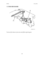
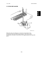
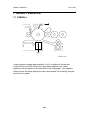
1.2 DRIVE MECHANISM
[B]
[A]
A184D500.wmf
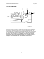
The drum [A] is driven by the main motor [B] through idle gears.
2-2
4 July 1996
CHARGE
2. CHARGE
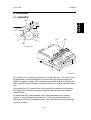
2.1 OVERVIEW
Detailed
Descriptions
[A]
[C]
[D]
[B]
A184D501.wmf
A184D502.wmf
This copier uses a single wire scorotron to charge the drum. The corona wire
[A] generates a corona of negative ions when the high voltage supply unit
applies a negative voltage. The stainless steel grid plate [B] ensures that the
drum coating receives a uniform negative charge as it rotates past the corona
unit.
The exhaust fan [C] causes a flow of air through the charge corona section.
This prevents an uneven build-up of negative ions that can cause uneven
image density.
An ozone filter [D], which adsorbs ozone (O3) generated by the charge
corona, is located beside the exhaust fan. The ozone filter decreases in
efficiency over time as it adsorbs ozone. The ozone filter should be replaced
every 30 k copies.
2-3
CHARGE
4 July 1996
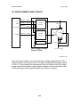
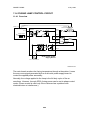
2.2 CHARGE CORONA CIRCUIT
CN123-4
CN1-1
CN123-3
CN1-2
CN123-2
CN1-3
24 V
GND
CT Trigger
DC/DC
Inverter
3 MΩ
G
B
B PWM
CN123-1 CN1-4
Drum
DC/DC
Inverter
Zener Diode
High Voltage Supply
Board-CT/B/G
620 V
To Drum GND
A184D503.wmf
The main board supplies +24 V to the high voltage supply board at CN123-4
as the power source. After the Start key is pressed, the CPU drops CN123-2
from +24 V to 0 V. This activates the charge corona circuit which applies a
high negative voltage of approximately –5 k volts to the charge corona wire.
The corona wire then generates a negative corona charge.
The grid plate limits the charge voltage to ensure that the charge does not
fluctuate and that an even charge is applied to the entire drum surface. The
grid plate is connected to ground through a zener diode in the high voltage
supply unit. The grid plate drains any charge in excess of –850 V, which is
discharged to the ground through the zener diode.
2-4
4 July 1996
OPTICS
3. OPTICS
3.1 OVERVIEW
[B]
[A]
[F]
[E]
Detailed
Descriptions
[C]
[J]
[H]
[D]
[G]
[I]
A184D504.wmf
During the copy cycle, an image of the original is reflected onto the drum
surface through the optics assembly as follows:
Light path:
Exposure Lamp [A] → Original → First Mirror [B] → Second Mirror [C] →
Third Mirror [D] → Lens [E] → Fourth Mirror [F] → Fifth Mirror [G] → Sixth
Mirror [H] → Drum [I]
This copier has five (metric version) or four (inch version) standard
reproduction ratios (A184 copier only) and a zoom function. The operator can
also change the reproduction ratio in one-percent steps from 70% to 141%.
One stepper motor is used to change the positions of the lens and 4th/5th
mirrors to enlarge/reduce the image across the page. Changes in
reproduction ratio down the page are achieved by changing the scanner
speed (A184 copier only).
The CPU monitors the temperature around the optics through a thermistor
which is located on the scanner frame. When the temperature reaches 35°C,
the optics cooling fan [J] (230 V machines only) starts rotating to draw cool
air into the optics cavity. The fan operates until the temperature drops below
32°C. (However, 120 V machines are not equipped with a cooling fan.) For all
models, the machine will stop if the optics cavity overheats to a certain
temperature. (See Troubleshooting for details.) In this case, the Start key
turns red.
Additionally, a thermofuse on the 1st scanner provides back-up overheat
protection. It opens when the temperature reaches 128°C and cuts ac power
to the exposure lamp.
2-5
OPTICS
4 July 1996
3.2 SCANNER DRIVE
[H]
[F]
[C]
[D]
[A]
[E]
[B]
[G]
A184D505.wmf
A stepper motor [A] is used to drive the scanners.
The first scanner [B], which consists of the exposure lamp and the first mirror,
is connected to the first scanner belt [C]. The second scanner [D], which
consists of the second and third mirrors, is connected to the second scanner
belt [E]. Both the scanners move along the guide rail [F].
The pulley [G] drives both the first and second scanner belts. The 2nd
scanner moves at half the speed of the first scanner. This maintains the focal
distance between the original and the lens during scanning.
The scanner home position is detected by the home position sensor [H]. The
scanner return position is determined by counting the scanner motor drive
pulses.
2-6
4 July 1996
OPTICS
3.3 LENS AND 4TH/5TH MIRROR DRIVE (A184 copier only)
[B]
Detailed
Descriptions
[D]
[C]
[A]
[E]
[F]
A184D506.wmf
Drive from the lens & mirror motor [A] is transmitted to the timing belt [B] on
which the lens unit [C] is clamped. The lens position is changed to provide
the proper optical distance between the lens and the drum surface
corresponding to the selected reproduction ratio. The home position of the
lens is detected by the home position sensor [D]. The main board keeps track
of the lens position based on the number of pulses sent to the lens motor.
Drive from the lens & mirror motor is also transmitted to the 4th/5th mirror
drive cam [E]. As the lens unit position is changed, the cam rotates to change
the 4th/5th mirror [F] position to provide proper the focal distance between
the lens and the drum.
2-7
OPTICS
4 July 1996
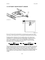
3.4 AUTOMATIC IMAGE DENSITY SENSOR
[A]
A184D525.wmf
sampled
area
A184D529.wmf
The auto ID sensor [A], a photodiode, is mounted on the upper front frame.
The sensor cover has a hole in it to allow light to fall directly onto the sensor.
Sampling starts 6 millimeters from the leading edge of the original and
continues for 11.5 millimeters from the leading edge of original in full size
mode. These lengths "a" and "b" will vary depending on the selected
reproduction ratio (A184 copier only). The lengths "a" and "b" for each
reproduction ratio are calculated as follows:
The photosensor circuit converts the light intensity to a voltage. The detected
voltage is amplified and sent to the main board. If less light is reflected from
the original (the image is darker), the sensor outputs a lower voltage. The
CPU compares the maximum detected voltage with the standard voltage and
compensates the copy image density by changing the development bias
voltage.
2-8
4 July 1996
OPTICS
3.5 EXPOSURE LAMP VOLTAGE CONTROL
The main board controls the exposure lamp voltage through the ac drive/dc
power supply board.
Lamp Voltage
= Base Lamp Voltage Setting (SP48)
+
Image Density Adjustment Factor (SP34)
+
Manual Image Density Setting Factor (SP35)
+
VL Correction Factor (SP62)
+
Reproduction Ratio Correction Factor
1) Base Lamp Voltage Setting
The lamp voltage is determined by the SP48 setting.
Base Lamp Voltage = SP48 setting x 0.5 (120 V machines)
SP48 setting x 1.0 (230 V machines)
The default setting is: 137 = 68.5 V (120 V machines)
128 = 128 V (230 V machines)
The current lamp voltage can be viewed with SP 51.
2) Image Density Adjustment Factor (SP34)
Depending on the SP34 setting, the development bias and the exposure
lamp data are increased or decreased for both ADS and manual ID modes.
SP34 Setting
0
1
2
3
4
5
6
Setting
Normal
Light
Dark
Lighter
Darker
Lightest
Darkest
Dev. Bias
0
–40 V
+40 V
–40 V
+40 V
–40 V
+40 V
2-9
Exposure Lamp
0
0
0
+3 steps
–3 steps
+7 steps
–7 steps
Detailed
Descriptions
The exposure lamp voltage is determined by the following factors:
OPTICS
4 July 1996
3) Manual Image Density Setting Factor
Depending on the manual image density setting on the operation panel, the
exposure lamp voltage is changed as shown in the table below:
Darker
Manual ID Level
Base Development
Bias Voltage (Volts)
Manual Image
Setting Factor
(Volts)
Lighter
1
2
ADS (3)
4
–200
–200
(–200)
–200
V0 – 6 steps
V0 – 3 steps
(SP35)
V0
5
–240
(SP36)
V0 + 3 steps V0 + 7 steps
V0: Base lamp voltage setting (SP48)
1 step = 0.5 V (120 V machines) or 1.0 V (230 V machines)
The manual setting factor for ID level 1 can be changed using SP35.
SP35 Setting
0
1
2
Image Adjustment at ID Level 1
–6 steps
–8 steps
–10 steps
4) VL Correction Factor
The light intensity may decrease because of dust accumulated on the optics
parts. Additionally, the drum sensitivity gradually decreases during the drum’s
life. This may cause dirty background on copies. To compensate this, VL
correction is done.
The exposure lamp voltage is increased by +1.0 V (230 V machines), or
+0.5 V (120 V machines) at the set copy count interval. The table below
shows the relationship between the SP setting and the interval.
SP62 Setting
0
1
2
3
4
5
6
7
8
VL Correction Interval
1 step/1500 copies
1 step/1000 copies
1 step/2000 copies
1 step/500 copies
1 step/2500 copies
1 step/250 copies
1 step/3000 copies
1 step/4000 copies
No Correction
(Default setting: 0)
2-10
4 July 1996
OPTICS
5) Reproduction Ratio Correction Factor
Magnification Ratio
70% to 72%
73% to 78%
79% to 119%
120% to 129%
130% to 141%
Reproduction Ratio Correction Factor
+4 steps
+2 steps
0
+4 steps
+8 steps
2-11
Detailed
Descriptions
The exposure lamp voltage is increased depending on the selected
magnification ratio in order to compensate for the change in concentration of
light on the drum.
ERASE
4 July 1996
4. ERASE
4.1 OVERVIEW
[A]
A184D507.wmf
a
b c d e f g
h
g f e d c b
a
A184D508.wmf
The erase lamp [A], which is installed in the upper unit, consists of a single
row of LEDs extended across the full width of the drum. The erase lamp has
the following functions: leading edge erase, side erase (A184 copier only),
and trail edge erase.
2-12
4 July 1996
ERASE
The entire line of LEDs turn on when the main motor turns on. They stay on
until the erase margin slightly overlaps the lead edge of the original image
area on the drum (Lead Edge Erase Margin). This prevents the shadow of
the original edge from being developed on the copy. At this point, side erase
starts (A184 copier only). The width of the leading erase margin can be
adjusted using SP41.
4.3 SIDE ERASE (A184 COPIER ONLY)
Based on the reproduction ratio, the LEDs turn on in blocks (labeled "a" - "h"
on the previous page). This reduces toner consumption and drum cleaning
load.
The CPU determines which blocks to turn on based on the selected
reproduction ratio as follows:
Reproduction Ratio (%)
70 to 72
73 and 74
75 to 77
78 and 79
80 and 81
82 to 84
85 to 141
Blocks ON
a-g
a-f
a-e
a-d
a-c
a-b
a
4.4 TRAILING EDGE ERASE
This minimizes toner consumption.
The entire line of LEDs turns on after the trailing edge of the latent image has
passed 10 mm from the erase lamp. The length of the latent image is
determined by the paper length which is checked by the registration sensor.
The LEDs stay on to erase the leading edge of the latent image in the next
copy cycle. After the final copy, the erase lamps turn off at the same time as
the main motor.
2-13
Detailed
Descriptions
4.2 LEAD EDGE ERASE
DEVELOPMENT
4 July 1996
5. DEVELOPMENT
5.1 OVERVIEW
[A]
[C]
[D]
[E]
[B]
A184D509.wmf
When the main motor turns on, the development roller [A] and two agitators
[B] and [C] start turning.
There are permanent magnets in the development roller which attract the
developer (which is about 50 µm in diameter) to the roller. The turning sleeve
of the development roller carries the developer past the doctor blade [D]
which trims the developer to the desired thickness.
The development roller sleeve continues to turn, carrying the developer to the
drum [E]. When the developer brush contacts the drum surface, the
negatively charged areas of the drum surface attract and hold the positively
charged toner. In this way, the latent image is developed.
The development roller is given a suitable negative bias for preventing toner
from being attracted to the non-image areas on the drum which may have a
residual negative charge. The bias also controls image density.
2-14
4 July 1996
DEVELOPMENT
5.2 DRIVE MECHANISM
[B]
Detailed
Descriptions
[C]
[A]
A184D510.wmf
When the main motor [A] turns on, the drive is transmitted to the
development roller gear [B] through idle gears. The rotation of the
development roller gear is transmitted to the agitator gears [C] through idle
gears.
2-15
DEVELOPMENT
4 July 1996
5.3 CROSS-MIXING
[B]
[D]
[C]
[A]
A184D511.wmf
A cross-mixing mechanism is used to keep the toner and developer evenly
mixed. It also helps agitate the developer to prevent developer clumps from
forming and helps create the triboelectric charge.
Two agitators (helical coils) [A] and [B] are used for the cross-mixing. The 1st
agitator [A] moves the developer from left to right. The toner supplied from
the cutout in the toner cartridge holder is mixed with the developer by the 1st
agitator. The 2nd agitator [B] rotates in the opposite direction and moves the
developer back from right to left. In this way, the developer is evenly
distributed in the development unit.
The magnets in the development roller [C] attract the developer, and the
development roller sleeve rotates to carry the developer to the drum. The
doctor blade [D] trims the developer on the development roller to the desired
thickness.
2-16
4 July 1996
DEVELOPMENT
5.4 DEVELOPMENT BIAS FOR IMAGE DENSITY CONTROL
Applying a bias voltage to the development sleeve reduces the potential
between the development roller and the drum, thereby reducing the amount
of toner transferred. As the bias voltage becomes greater, the copy becomes
lighter.
The method of control depends on whether the image density is manually
selected or auto image density is used.
The development bias voltage applied to the development roller sleeve has
the following factors:
Development bias voltage = Base bias voltage factor
(Manual ID level 5: SP 36)
+
Image density adjustment factor
(SP34)
+
Drum residual voltage (VR) correction factor
The base bias voltage for non-image areas (between copies) is –200 volts.
The above correction factors are also applied.
NOTE: SP34 (Image Density Adjustment) is applied for both ADS and
manual ID modes. SP36 is for manual ID level 5 only.
5.4.1 Base Bias Voltage Factor In Manual Image Density Mode
Manual ID Level
Base Bias Voltage
(Volts)
Base Exposure
Lamp Voltage
(Volts)
1
2
ADS (3)
4
–200
–200
(–200)
–200
V0 – 6 steps
V0 – 6 steps
(SP35)
V0
5
–240
(SP36)
V0 + 3 steps V0 + 7 steps
V0: Depends on the setting of SP48
The base voltage applied at each ID level is shown in the above table.
Normally, notch 3 is used for the ADS mode. If SP mode 19 is changed from
0 to 1, ADS mode is disabled and notch 3 is used for the center setting of the
manual ID level. The base exposure lamp voltage also varies depending on
the manual ID level as shown.
2-17
Detailed
Descriptions
The image density is controlled by changing two items: the amount of bias
voltage applied to the development roller sleeve, and the amount of voltage
applied to the exposure lamp.
DEVELOPMENT
4 July 1996
Adjustment factor for manual ID level 5 (SP36)
The base bias voltage at manual ID level 5 can be changed using SP36 as
follows:
Image Density
SP36 Setting
Normal
Lighter
Lightest
0
1
2
Base Bias Voltage Change for Level 5
(Volts)
–40
–80
–120
(Default setting: 0)
5.4.2 Base Bias Voltage Factor In Automatic Image Density (ADS) Mode
In ADS mode, the base exposure lamp voltage is fixed at V0 (this value is
determined by SP48). Image density is controlled by changing only the base
bias voltage.
The base bias voltage for ADS mode depends on the background image
density of the original which is measured by the ADS sensor. (See page 2-8
for more information about the ADS sensor).
The CPU checks the voltage output from the automatic ID circuit. This circuit
has a peak hold function. The peak hold voltage corresponds to the
maximum reflectivity of the original. The CPU then determines the proper
base bias level with reference to the peak hold voltage.
The table below shows the relationship between the original background
density (ADS voltage ratio) and the base bias voltage.
ADS Voltage Ratio [α] (%)
80 to 100 (light)
75 to 79
70 to 74
60 to 69
29 to 59
0 to 28 (dark)
α=
Base Bias Voltage
–200 V
–240 V
–280 V
–320 V
–360 V
–380 V
ADS Output Voltage
VADS0 + (Total VL Correction Steps so far + Reproduction Correction Steps) x 0.5
VADS0: ADS Reference Voltage
2-18
4 July 1996
DEVELOPMENT
Using SP 34, the base bias voltage and the exposure lamp data can be
increased or decreased for both ADS mode and all manual ID levels as
follows:
SP34 Setting
0
1
2
3
4
5
6
Setting
Normal
Light
Dark
Lighter
Darker
Lightest
Darkest
Dev. Bias
0
–40 V
+40 V
–40 V
+40 V
–40 V
+40 V
Exposure Lamp
0
0
0
+3 steps
–3 steps
+7 steps
–7 steps
(Default setting: 0)
5.4.4 Drum Residual Voltage (VR) Correction Factor
During the drum’s life, drum residual voltage (VR) will gradually increase. To
compensate for this, the bias voltage is increased by –10 V every 5 k copies.
The VR correction is done up to 20 k copies. The VR correction will not
change after 20 k copies.
2-19
Detailed
Descriptions
5.4.3 Image Density Adjustment Factor
DEVELOPMENT
4 July 1996
5.5 DEVELOPMENT BIAS CIRCUIT
CN123-4
CN1-1
CN123-3
CN1-2
CN123-2
CN1-3
24 V
GND
CT Trigger
DC/DC
Inverter
3 MΩ
G
B
B PWM
CN123-1 CN1-4
Drum
DC/DC
Inverter
Zener Diode
High Voltage Supply
Board-CT/B/G
620 V
To Drum GND
A184D503-2.wmf
The main board supplies +24 volts to the high voltage supply board at CN1-1.
When the Start key is pressed, the CPU starts sending the bias trigger pulses
to CN1-4. This energizes the development bias circuit within the high voltage
supply board which applies a high negative voltage to the development roller.
The development bias is applied whenever the drum is rotating.
2-20
4 July 1996
TONER SUPPLY
6. TONER SUPPLY
6.1 TONER SUPPLY MECHANISM
Detailed
Descriptions
[B]
[D]
[H]
[C]
[G]
[J]
[I]
[F]
[A]
[K]
[E]
A184D512.wmf
When the toner bottle [A] is set and the lever [B] is pushed down, the chuck
[C] pulls out the cap [D], and the toner bottle is opened.
While the TD (toner density) sensor detects enough toner in the developer,
the toner supply clutch [E] is off, and the main motor drive is not transmitted
to the gear [F]. When the TD sensor detects a low toner condition, the toner
supply clutch is energized and the drive is transmitted to the gear [G] through
idle gears. The gear [G] drives the toner bottle gear [H], and the toner bottle
rotates in the direction of the arrow.
The toner bottle has a spiral groove that helps move toner to the toner bottle
opening [I]. Then the toner is carried up to the opening [J] of the toner bottle
holder by the rotating fins [K], to be supplied into the development unit.
2-21
TONER SUPPLY
4 July 1996
6.2 TONER DENSITY DETECTION
[A]
[B]
A184D511-2.wmf
A toner density sensor (TD sensor) [A] is used for toner density control.
The TD sensor is located under the 1st agitator [B]. The developer being
conveyed by the 1st agitator passes over the top of the sensor. As the toner
in the developer is consumed during development, the toner to carrier ratio
changes resulting in a change in the magnetic permeability of the developer.
This in turn is converted to a corresponding voltage. The CPU monitors the
voltage to control the toner supply mechanism.
When a new imaging unit is installed, the machine starts idling for developer
initialization. During the developer initialization, the CPU adjusts the TD
sensor control voltage so that the TD sensor outputs 1.9 ± 0.1 volts for the
toner to carrier ratio of new developer (4.0% by weight). This voltage is used
as the standard TD sensor voltage.
2-22
4 July 1996
TONER SUPPLY
6.3 TONER SUPPLY CONTROL
6.3.1 Modes Available
0
1
2
3
4
Toner Supply
Mode
Detect Supply
Mode
Target Toner
Toner Supply
Sensor Voltage
Amount
Depends on the
Depends on the
initial TD sensor
TD sensor output.
setting.
Depends on SP53. Depends on the
TD sensor output.
Depends on the
Fixed
initial TD sensor
setting.
Depends on SP53. Fixed
Fixed Supply Mode None
Fixed
Toner Near/End
Detection
P
P
Default setting: 0
Depending on the SP30 setting, Detect Supply mode or Fixed Supply mode
is selected. If 0, 1, 2, or 3 is selected in SP30, Detect Supply mode is used. If
4 is selected, Fixed Supply mode is used.
Note that when 2, 3, or 4 is selected, the machine will not perform the toner
near/end detection. Normally, SP30 should always be kept at the default
setting. The following pages describes in detail of each toner supply mode
settings.
6.3.2 Detect Supply Mode
In Detect Supply mode, the CPU monitors the TD sensor voltage, which
depends on the toner to carrier ratio in the developer. As the toner in the
developer is consumed, the TD sensor output voltage increases.
The TD sensor voltage is compared with the standard voltage (known as the
Target Toner Sensor Voltage), and toner is supplied when the TD sensor
output is higher than this target voltage.
The machine has two ways of calculating the target toner sensor voltage; the
method used depends on SP30. The toner supply amount can also be
changed using SP31 or 32.
2-23
Detailed
Descriptions
SP30
Setting
TONER SUPPLY
4 July 1996
1) Target Toner Sensor Voltage
– Method 1 –
Normally (if 0 or 2 is selected in SP30) the voltage is determined by the
following factors:
Target Toner Sensor Voltage (VTS) = Initial Developer Setting Voltage (VT0)
+
Toner Density Adjustment Factor
a) Initial Developer Setting Voltage (VT0)
This voltage is adjusted to 1.9 ± 0.1 V during the developer initialization (refer
to section 6.2).
b) Toner Density Adjustment Factor
The target toner density can be changed by customers or service engineers
using SP mode 38 or user tool No. 4.
SP 38 Setting
0
1
2
3
4
User Tool 4
Setting
0
1
2
Toner Density
Normal
Higher
Lower
Highest
Lowest
Toner Density
Adjustment Factor (β)
0
–S x 1/2
+S x 1/2
–S
+S
S: TD Sensor Sensitivity (SP24)
Default: Normal
The sensor sensitivity is stored in SP24.
TD Sensor Sensitivity (S) [V/wt%] =
Change of TD sensor output [V]/Change of toner density [wt%] =
SP24 setting x 0.05 [V] (Default: SP24 = 8)
– Method 2 –
If 1 or 3 is selected in SP30, the setting of SP53 is used as the target toner
sensor voltage. In this case, the target toner sensor voltage is determined by
the following formula:
Target Toner Sensor Voltage = SP53 setting x 0.02 [V] (Default: 97 = 1.94 V)
2-24
4 July 1996
TONER SUPPLY
– Method 1 –
Normally (if 0 or 1 is selected in SP30), the toner supply amount is
determined by the difference between the TD sensor voltage (VT) and the
target toner sensor voltage (VTS). The following table shows the relationship
between the sensor output and the toner supply clutch on time for each copy.
Toner Supply Level
1
2
3
TD Sensor Voltage Level [VT]
VTS < VT ≤ VTS + S/16
4
5
6 (Near End Level)
VTS + S/4 < VT ≤ VTS + S/2
7 (Toner End Level)
VT ≥ VTS + S
Toner Supply Clutch On Time
t
VTS + S/16 < VT ≤ VTS + S/8
VTS + S/8 < VT ≤ VTS + S/4
VTS + S/2 < VT ≤ VTS + 4S/5
VT ≥ VTS + 4S/5
2xt
4xt
8xt
13 x t
16 x t
16 x t
The toner supply time step "t" can be changed using SP31.
t = SP31 setting x 0.1 [second] (Default: 1 = 0.1 second)
S: TD Sensor Sensitivity (SP24)
In the toner supply level 6 and 7, after a copy job is finished, the main motor
continuously rotates, and the toner supply clutch is energized intermittently
for T seconds (repeatedly 2 seconds on and 2 seconds off during this
T-second interval).
The interval "T " can be changed using SP23.
– Method 2 –
If 2 or 3 is selected in SP30, a fixed amount of toner is supplied when the TD
sensor voltage becomes higher than the target toner sensor voltage. The
amount of toner can be selected using SP32.
SP32 Setting
0
1
2
3
4
5
6
7
Toner Supply Clutch On Time
(seconds)
0.3
0.6
1.2
2.4
3.6
4.8
Stays on until the TD sensor
voltage becomes lower than the
target voltage.
0 (No toner supply)
Corresponding image area ratio
(%)
3.5
7
15
30
45
60
0
Example: Set SP32 to 2 if the customer’s originals are typically 15% black.
2-25
Detailed
Descriptions
2) Toner Supply Amount
TONER SUPPLY
4 July 1996
6.3.3 Fixed Supply Mode
If 4 is selected in SP30, the TD sensor is not used for toner supply control. A
fixed amount of toner is supplied at every copy cycle. The toner supply
amount is determined by the SP32 setting.
6.3.4 TD Sensor Check and Toner Supply Timing
During every copy cycle, the TD sensor voltage is monitored for three
seconds after the machine starts developing the image on the drum. The
CPU checks the voltage every 40 ms and stores the second highest voltage
of every 250 ms period. Then the stored voltages during the three seconds
are averaged, and the average is used as the TD sensor value for the copy.
The toner supply clutch on time for detect supply mode using TD sensor
output depends on this value.
If the machine determines that toner needs to be added, the toner supply
clutch turns on just after the trailing edge of the copy paper passes the
transfer corona unit. If the copy paper is shorter than A4/LT size, the clutch is
energized for 3 seconds after the machine starts developing the latent image.
6.3.5 Abnormal Condition in Toner Density Detection
If the calculated value of the TD sensor goes below 0.2 volts, the CPU
determines that the toner density detection is abnormal. The CPU changes
from the detect supply mode to the fixed supply mode. At the same time,
either the Auto ID indicator or the selected manual ID level starts blinking,
and the machine can be operated. Under this condition, the machine will not
perform the toner end detection.
If the value recovers above 0.2 volts, or the main switch is turned off and on,
this condition is canceled and the toner density detection will recover to the
previous settings.
2-26
4 July 1996
TONER SUPPLY
6.4 TONER END CONDITION
If the CPU detects toner supply level 6 (VT ≥ VTS + 4S/5) five times
consecutively, the toner end indicator blinks and the machine goes to the
toner near end condition. In this condition, the toner supply clutch is
energized for 16t seconds for every copy. If a toner sensor voltage lower than
VTS + 4S/5 is detected twice consecutively during the copy cycle, the
machine recovers from the toner near end condition. (As explained before, t
depends on SP31.)
If the toner sensor voltage does not recover from level 6 during the copy
cycle, the main motor continuously rotates after the copy job is finished, and
the toner supply clutch is energized intermittently for T seconds (T can be
changed using SP23). The CPU monitors the TD sensor voltage during this T
seconds. If the toner sensor voltage returns to level 5 or less in this period,
the machine recovers from the toner near end condition and the main motor
stops.
6.4.2 Toner End
If TD sensor level 6 is detected, the machine supplies toner for T seconds
after the copy job is finished. During this T seconds, if the CPU detects TD
sensor level 7 (VT ≥ VTS + S) three times consecutively, a toner end
condition is detected and copier operation is disabled.
If the toner sensor voltage stays in level 6 during the T seconds, the machine
keeps the toner near end condition and 50 more copies can be made. After
50 copies, the toner end indicator lights and copying is disabled.
6.4.3 Toner End Recovery
If the main switch is turned off and on, or the upper unit is opened and closed
during a toner end condition, the main motor turns on and the toner supply
clutch is intermittently energized. If the TD sensor voltage does not recover
from level 7 within 40 seconds, the machine stops, keeping the toner end
condition. If the TD sensor voltage level recovers to level 6 or less in this
period, the toner supply clutch on time is reduced and the main motor
continuously rotates for 40 seconds to evenly distribute toner inside the
development unit. The on/off timing of the clutch is set using SP25 and 26.
(These settings should not be changed.)
2-27
Detailed
Descriptions
6.4.1 Toner Near End
IMAGE TRANSFER
4 July 1996
7. IMAGE TRANSFER
7.1 OVERALL
[A]
A184D513.wmf
A high negative voltage (approximately –6 kV) is applied to the transfer
corona wire [A], and the corona wire generates negative ions. These
negative ions are applied to the back side of the copy paper. This negative
charge forces the paper against the drum and attracts the positively charged
toner onto the paper.
2-28
4 July 1996
IMAGE TRANSFER
CN123-4
CN1-1
CN123-3
CN1-2
CN123-2
CN1-3
24 V
GND
CT Trigger
DC/DC
Inverter
3 MΩ
G
B
B PWM
CN123-1 CN1-4
Drum
DC/DC
Inverter
Zener Diode
High Voltage Supply
Board-CT/B/G
620 V
To Drum GND
A184D503-3.wmf]
The terminal which applies high negative voltage to the transfer corona is the
same as the terminal for the charge corona. So when the CPU drops
CN123-2 from +24 V to 0 V, both the transfer corona and charge corona are
applied to the drum at the same time. To apply the proper transfer current to
the drum, the transfer corona casing is connected to ground through a
varistor. This keeps the potential of the casing at –620 volts to prevent
excess corona current from flowing into the casing.
2-29
Detailed
Descriptions
7.2 TRANSFER CORONA CIRCUIT
DRUM CLEANING
4 July 1996
8. DRUM CLEANING
8.1 OVERVIEW
[A]
A184D514.wmf
A counter blade system is used for drum cleaning. The cleaning blade [A]
scrapes off any toner remaining on the drum after the image is transferred to
the paper.
The removed toner is transported into the developer to be recycled.
2-30
4 July 1996
DRUM CLEANING
8.2 TONER RECYCLING MECHANISM
Detailed
Descriptions
[A]
[B]
A184D515.wmf
The toner removed from the drum falls onto the toner collection coil [A]. The
drum gear rotation is directly transmitted to the gear of the toner collection
coil.
As the coil rotates, the toner moves from left to right to be transported to the
toner recycling belt [B]. The paddles of the belt, which is driven by the toner
collection coil shaft, transports the toner into the developer, and the toner is
recycled.
2-31
QUENCHING
4 July 1996
9. QUENCHING
[A]
A184D507-2.wmf
In preparation for the next copy cycle, light from the quenching lamp (QL) [A],
which is installed in the upper unit, neutralizes any charge remaining on the
drum.
LEDs are used for quenching and the lamp is turned on whenever the main
motor rotates.
2-32
4 July 1996
PAPER FEED AND REGISTRATION
10. PAPER FEED AND REGISTRATION
[C]
[D]
[E]
[B]
[A]
A184D516.wmf
This copier has one paper feed station and a by-pass feed table.
The paper feed station uses a paper tray [A] which can hold 250 sheets. The
by-pass feed table [B] can hold 1 sheet.
The paper tray uses two semicircular feed rollers [C] and a corner separator.
The semicircular feed rollers make one rotation to drive the top sheet of the
paper stack to the relay rollers [D].
The paper tray has two corner separators, which allow only one sheet to
feed. They also serve to hold the paper stack.
If a sheet of paper is set on the by-pass feed table, the registration sensor [E]
is actuated and the machine goes to by-pass feed mode.
2-33
Detailed
Descriptions
10.1 OVERVIEW
PAPER FEED AND REGISTRATION
4 July 1996
10.2 PAPER FEED MECHANISM
[D]
[C]
[A]
[E]
[B]
A184D517.wmf
[F]
A184D518.wmf
Through several gears, main motor rotation is transmitted to the paper feed
clutch gear [A]. The rotation of the paper feed clutch gear is transmitted to the
relay roller gear [B] through an idle gear.
After the Start key is pressed, the solenoid [C] of the paper feed clutch is
energized to release the stopper [D], and the rotation of the relay roller gear
is transmitted to the feed roller shaft [E]. The solenoid stays on for 250
milliseconds and then turns off. The feed rollers stop when they complete one
rotation.
Before the feed rollers stop, the leading edge of the paper is caught by the
relay rollers [F].
2-34
4 July 1996
PAPER FEED AND REGISTRATION
Detailed
Descriptions
10.3 REGISTRATION MECHANISM
[A]
[B]
[C]
A184D524.wmf
The relay rollers always rotate while the main motor rotates. They transport
the paper to the registration roller [A]. The registration roller is also driven by
the main motor through idle gears.
There is a paper stopper [B] between the relay roller and the registration
roller. After the leading edge of the paper reaches the stopper, a small buckle
is made between the relay roller and the registration roller. 2.7 seconds after
the paper feed clutch is turned on, the registration solenoid [C] is energized
to release the stopper, synchronizing the paper feeding with the image on the
drum.
After 0.5 second, the registration solenoid is de-energized.
The registration sensor detects paper length and paper end.
2-35
PAPER FEED AND REGISTRATION
4 July 1996
10.4 BY-PASS FEED
[C]
[B]
[A]
[D]
A184D522.wmf
If a sheet of paper is inserted in the by-pass feed table [A], the registration
sensor [B] is actuated and the machine goes to by-pass feed mode. 500
milliseconds after the registration sensor is actuated, the main motor turns on
for 222 milliseconds to drive the relay roller [C] to catch the leading edge of
the paper. After the Start key is pressed, the main motor starts again to
transport the paper to the registration roller [D]. The registration solenoid is
energized 1912 milliseconds after the main motor started rotating.
2-36
4 July 1996
PAPER FEED AND REGISTRATION
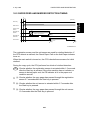
10.5 PAPER FEED AND MISFEED DETECTION TIMING
0
0.1
(second)
Detailed
Descriptions
Start Key
Main Motor
Paper Feed
Clutch
Registration
Sensor
Registration
Solenoid
1.5
5.7
PE
Paper Length Detection
ON Check 2.7
3.2
OFF Check
(1)
5.7
10.3
Exit Sensor
ON Check
(2)
(3)
A184D527.wmf
The registration sensor and the exit sensor are used for misfeed detection. If
the CPU detects a misfeed, the Check Paper Path or the Add Paper indicator
turns on.
When the main switch is turned on, the CPU checks these sensors for initial
misfeed.
During the copy cycle, the CPU performs four kinds of misfeed detection:
PE : Checks whether the registration sensor is actuated within 1.5 seconds
after the Start key is pressed. Since this machine has no indicator or
sensor to detect paper end, the PE indicator is lit in the paper end
condition as well.
(1): Checks whether the copy paper has passed through the registration
sensor 5.7 seconds after the Start key is pressed.
(2): Checks whether the exit sensor is actuated within 5.7 seconds after
the Start key is pressed.
(3): Checks whether the copy paper has passed through the exit sensor
10.3 seconds after the Start key is pressed.
2-37
IMAGE FUSING
4 July 1996
11. IMAGE FUSING
11.1 OVERVIEW
[C]
[A]
[E]
[E]
[D]
[F]
[B]
A184D520.wmf
After the image is transferred, the copy paper enters the fusing unit. The
image is fused to the copy paper by the process of heat and pressure
through the use of a hot roller [A] and pressure roller [B].
The CPU monitors the hot roller temperature through a thermistor [C] which
is in contact with the hot roller surface. A thermofuse [D] protects the fusing
unit from overheating.
The hot roller strippers [E] separate the copy paper from the hot roller and
direct it to the exit rollers. The exit sensor [F] monitors the progress of the
copy paper through the fusing unit and acts as a misfeed detector. The exit
rollers drive the copy paper to the copy tray.
2-38
4 July 1996
IMAGE FUSING
11.2 FUSING DRIVE MECHANISM
[B]
Detailed
Descriptions
[A]
[C]
[C]
A184D521.wmf
[E]
[E]
[D]
A184D523.wmf
The main motor [A] drive is transmitted to the hot roller [B] through idle gears.
The hot roller always rotates while the main motor rotates. While the upper
unit is open, the pressure roller [C] is not in contact with the hot roller. This
enables easy misfed paper removal at the fusing area.
When the upper unit is closed, the pressure roller is pushed up by the arms
[D]. The two springs [E] apply the proper fusing pressure between the hot
roller and the pressure roller.
2-39
IMAGE FUSING
4 July 1996
11.3 FUSING LAMP CONTROL
The CPU monitors the temperature of the hot roller surface using a
thermistor. The fusing lamp is turned on and off to keep the hot roller surface
at the target temperature. The target temperature depends on the machine
condition as follows:
A184D528.wmf
Machine Condition
After the main switch is turned
on, until one minute has past
after the fusing temperature
reaches 170°C.
Fusing Lamp
ON/OFF Threshold
185°C
After the above time period
150°C
During copying
After copying is finished
185°C
150°C
2-40
Remarks
After the fusing temperature
reaches 170°C (ready
temperature), the fusing lamp is
kept on until it reaches 185°C.
When the Start key is pressed, the
red indicator blinks and copying
starts after the fusing temperature
reaches 170°C.
4 July 1996
IMAGE FUSING
When the Start key is pressed, if the fusing temperature is higher than 170°C,
the machine starts copying immediately. If the temperature is lower, the
fusing lamp is turned on and the red start indicator blinks. Copying starts after
the fusing temperature reaches 170°C, and the fusing temperature is
controlled at 185°C during copying.
After copying is finished, the fusing temperature is controlled at 150°C.
To prevent any copy quality problem caused by exposure lamp intensity
fluctuation, the fusing lamp does not turn on while the exposure lamp is on,
even if the fusing temperature drops below 185°C.
2-41
Detailed
Descriptions
When the main switch is turned on, the CPU turns on the fusing lamp. When
the fusing thermistor detects 170°C, the machine enters the ready condition.
After the ready temperature is detected, the CPU keeps the fusing
temperature at 185°C for one minute, then the target temperature is changed
to 150°C.
IMAGE FUSING
4 July 1996
11.4 FUSING LAMP CONTROL CIRCUIT
11.4.1 Overview
CN121-10
CN121-11
5 V
CN121-8
24 V
Fusing
Thermistor
CN404-2
T408
Fusing Lamp
Trigger Pulse
24 V
0 V
CN121-7
PC2
T407
CN404-3
T405
Main Board
T406
T404
Main Switch
Interlock
Switch
T403
FU1
T402
T401
AC Drive/DC Power
Supply Board
AC Power Source
A184D519.wmf
The main board monitors the fusing temperature through a thermistor. It uses
the zero cross signal generated by the ac drive/dc power supply board to
control the applied power accurately.
Normally, the voltage applied to the lamp is the full duty cycle of the ac
waveform. However, through SP29, fusing power can be set to phase control
mode. (Phase control is used only if the customer has a problem with
electrical noise or interference.)
2-42
4 July 1996
IMAGE FUSING
When the main switch is turned on, the main board starts to output a trigger
pulse, which has the same timing as the zero cross signal, to the ac drive/dc
power supply board. This trigger pulse allows maximum ac power to be
applied to the fusing lamp. When the operating temperature is reached, the
CPU stops outputting the trigger pulse (the trigger stays HIGH) and the fusing
lamp turns off.
11.4.3 Phase Control Mode
A184D526.wmf
The main board sends the fusing lamp trigger pulse (LOW active) to the ac
drive/dc power supply board, which provides ac power to the fusing lamp at
the falling edge of each trigger pulse. The trigger pulse goes HIGH when the
main board receives the zero cross signal.
The amount of time that power is applied to the fusing lamp depends on the
temperature of the hot roller.
The trigger pulse (LOW part) is wider [C1] and power is supplied for longer
[D1] when the hot roller temperature is lower. It is narrower [C2] and power is
supplied for a shorter time [D2] when the hot roller is near the operating
temperature.
2-43
Detailed
Descriptions
11.4.2 On/Off Control
IMAGE FUSING
4 July 1996
11.4.4 Overheat Protection
There is an overheat protection circuit in the main board. If the hot roller
temperature reaches 230°C, the resistance of the thermistor (between
CN121-10 and CN121-11) becomes too low. If the main board detects this
condition, "E-53" lights on the operation panel and power to the fusing lamp
is cut.
Even if the thermistor overheat protection fails, the thermofuse opens when it
reaches 169°C, removing power from the fusing lamp.
2-44
SECTION 3
INSTALLATION
4 July 1996
INSTALLATION REQUIREMENTS
1. INSTALLATION REQUIREMENTS
1. Temperature Range:
10°C to 30°C (50°F to 87°F)
2. Humidity Range:
15% to 90% RH
3. Ambient Illumination:
Less than 1,500 lux (Do not exposure to direct
sunlight.)
4. Ventilation:
Minimum space 20 m3.
Room air should turn over at least 3 times per
hour
5. Ambient Dust:
Less than 0.15 mg/m3 (4 x 10⁻³ oz/yd3)
6. If the place of installation is air-conditioned or heated, do not place the
machine:
a) Where it will not be subjected to sudden temperature changes.
b) Where it will not be directly exposed to cool air from an air-conditioner.
c) Where it will not be directly exposed to heat from a heater.
7. Do not place the machine where it will be exposed to corrosive gasses.
8. Do not install the machine at any location over 2,000 m (6,500 feet)
above sea level.
9. Place the copier on a strong and level base.
10. Do not place the machine where it may be subjected to strong vibrations.
1.2 MACHINE LEVEL
1. Front to back:
Within 3 mm (0.12") of level
2. Right to left:
Within 3 mm (0.12") of level
3-1
Installation
1.1 ENVIRONMENT
INSTALLATION REQUIREMENTS
4 July 1996
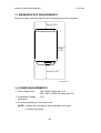
1.3 MINIMUM SPACE REQUIREMENTS
Place the copier near the power source, providing clearance as shown:
20 cm [7.8"]
20 cm
[7.8"]
40 cm [15.6"]
A184I516.wmf
1.4 POWER REQUIREMENTS
1. Input voltage level:
120 V/60 Hz: More than 10 A
220 ~ 240 V, 50/60 Hz: More than 6 A
2. Permissible voltage
fluctuation:
10%
3. Do not set anything on the power cord.
NOTE: a) Make sure the plug is firmly inserted in the outlet.
b) Avoid multi-wiring.
3-2
4 July 1996
INSTALLATION
2. INSTALLATION
2.1 ACCESSORY CHECK
Check the quantity and condition of the accessories in the box against the
following list:
1. Imaging Unit
2. Paper Feed Tray
4. Error Code Decal - Multi-language (-10, -22, -26, -27 machines)
5. Operating Instructions - English (-10, -17, -22, -26, -29, -57 machines)
6. Operating Instructions - Spanish (-17, -22, -26, -57 machines)
7. Operating Instructions - German (-26 machines)
8. Operating Instructions - French (-26 machines)
9. Operating Instructions - Italian (-26 machines)
10. Operating Instructions - Portuguese (-57 machines)
11. Model Name Decal (-10, -22, machines)
12. NECR - English (-57 machines)
13. NECR - Multi-language (-27, -29 machines)
14. Warranty Card (-17 machines)
15. User Registration Card (-17 machines)
3-3
Installation
3. Error Code Decal - English
INSTALLATION
4 July 1996
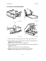
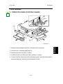
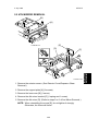
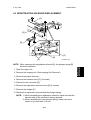
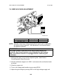
2.2 INSTALLATION PROCEDURE
[A]
A184I500.wmf
A184I503.wmf
[C]
[D]
[B]
A184I501.wmf
A184I506.wmf
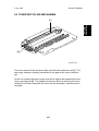
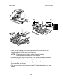
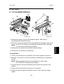
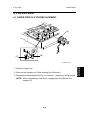
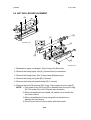
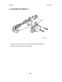
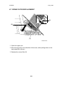
1. Remove the tape securing the platen cover, copy tray and power cord.
2. Open the platen cover and remove the two scanner locking pins [A] from
both sides of the exposure glass.
NOTE: Save the lock pins for future shipping use.
3. Take off the tape covering the screw and remove the knob screw [B] and
red tag [C] as shown.
NOTE: Save the knob screw for future shipping use.
4. Open the top unit and remove the 4th/5th mirror lock tool [D].
NOTE: Save the shipping retainer for future shipping use.
3-4
4 July 1996
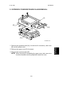
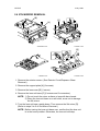
INSTALLATION
[A]
[B]
Installation
[B]
A184I508.wmf
[C]
A184I509.wmf
A184I510.wmf
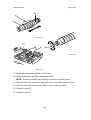
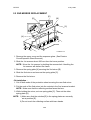
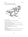
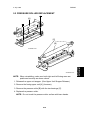
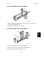
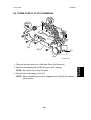
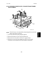
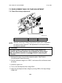
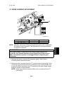
5. Take out the imaging unit from the cardboard box. Then remove the
protective sheet and the tape fixing the lever.
NOTE: 1) Do not touch the drum surface with bare hands.
2) Do not expose the drum to direct sunlight.
6. Remove the paper [A] from the inside of the copier (this paper contains
the installation procedure for the imaging unit).
7. Fit the imaging unit onto both hinges [B], as shown. Then, set the unit on
the guide plate, as shown.
8. Pull out horizontally and remove the tape [C] inside the imaging unit, as
shown.
3-5
INSTALLATION
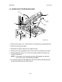
4 July 1996
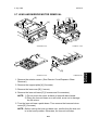
[A]
A184I512.wmf
[C]
[B]
A184I513.wmf
A184I514.wmf
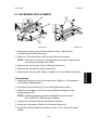
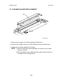
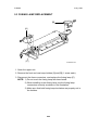
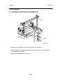
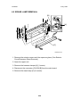
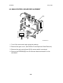
9. Shake the toner bottle [A] well 5 or 6 times.
10. Remove the black cap [B] from the toner bottle.
NOTE: Remove the black cap carefully so as not to spill any toner.
11. Open the lever [C] and put the cap side of the toner bottle under the lever.
12. Push the other side of the toner bottle in until it locks in position.
13. Close the lever [C].
14. Close the top unit.
3-6
4 July 1996
INSTALLATION
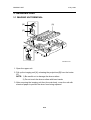
[A]
Installation
[B]
A184I502.wmf
[C]
A184I511.wmf
A184I507.wmf
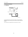
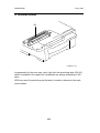
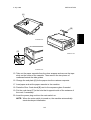
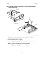
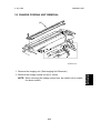
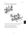
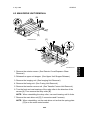
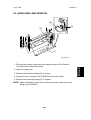
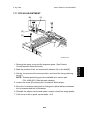
15. Take out the paper cassette from the clear wrapper and remove the tape
stuck on the center of the cassette. Then remove the two pieces of
cardboard beside the side guides.
16. Change the end plate [A] for the paper size the customer requests.
17. Load paper and set the paper cassette in the machine.
18. Paste the Error Code decal [B] next to the exposure glass if needed.
19. Put the cord clamp [C] in the hole that is opposite side of the entrance of
the cord, if necessary.
20. Insert the power plug and turn the main switch on.
NOTE: When the main switch is turned on, the machine automatically
starts developer initialization.
3-7
SECTION 4
SERVICE TABLES
4 July 1996
SERVICE REMARKS
1. SERVICE REMARKS
1.1 GENERAL CAUTIONS
1. To prevent physical injury, keep hands away from the mechanical drive
components when the main switch is on (especially during the warm-up
cycle).
If the Start key is pressed before the copier finishes the warm-up cycle,
the Start indicator starts blinking and the copier starts making copies as
soon as the warm-up cycle is completed.
2. Before disassembling or assembling any parts of the copier, make sure
that the power cord is unplugged.
3. To avoid possible injury or machine damage, always hold the upper unit
firmly with your other hand when opening the upper unit.
Service
Tables
4. Keep all the shipping retainers for future shipping use.
1.2 IMAGING UNIT
1. Always make sure of the following when removing the imaging unit from
the copier.
• Do not touch the drum surface with bare hands. When the drum
surface is touched with fingers or becomes dirty, wipe it with a dry
cloth.
• Place the imaging unit on a clean and level place. Take care not to
scratch the drum from under the unit as there is no cover to protect it.
• Cover the imaging unit with sheets of paper to prevent the drum from
being exposed to light.
• Do not turn the imaging unit upside down. Toner and developer may
fall out from the unit.
2. Always cover the imaging unit with sheets of paper when the upper unit is
opened.
3. Never use alcohol to clean the drum; alcohol dissolves the drum surface.
4. Take care not to scratch the drum as the photoconductive layer is thin
and is easily damaged.
5. Never expose the drum to corrosive gases such as ammonia gas.
6. When placing the imaging unit onto the copier, do not push it down
forcibely. This unit is set only to put it on the guide plate. (The imaging
unit is shaky if you push it — this is not a problem.)
4-1
SERVICE REMARKS
4 July 1996
7. Do not touch the charge corona wire and the grid plate with bare hands.
Oil stains may cause uneven image density on copies.
8. Clean the charge corona wire by sliding the wire cleaning tool from right
to left.
9. Clean the charge grid with a blower brush (not with a cloth).
10. Be careful not to damage the edge of the cleaning blade.
11. After installing a new cleaning blade, be sure to apply setting powder
evenly on the surface and edge of the blade.
1.3 OPTICS
1. Clean the exposure glass with glass cleaner and a dry cloth to reduce the
amount of static electricity on the glass surface.
2. Only use a clean soft cloth to clean the mirrors and reflectors.
3. Only use a blower brush to clean the 6th mirror and the lens.
4. Do not touch the following parts with bare hands:
a) Reflectors
b) Exposure Lamp
c) Mirrors and Lens
5. Do not change the cutout position of the reflectors as they are adjusted at
the factory.
6. Always replace the 1st scanner unit as an assembly, as the matching of
each set of exposure lamp and reflectors is performed at the factory.
7. Whenever cleaning the optics, all the following actions must be done in
order.
a) Optics cleaning
b) SP95 (VL Correction Reset)
c) SP48 (Light Intensity Adjustment) – see the SP mode table for details
d) SP56 (ADS Reference Voltage Adjustment) – see the SP mode table
for details
4-2
4 July 1996
SERVICE REMARKS
1.4 TRANSFER CORONA
1. Clean the corona wire by sliding the wire cleaning tool from right to left.
1.5 FUSING UNIT
1. Be careful not to damage the edges of the hot roller strippers or their
tension springs.
2. Do not touch the fusing lamp with bare hands.
3. Make sure that both fusing lamp insulators are properly set in the holders.
1.6 PAPER FEED
1. Do not touch the feed rollers with bare hands.
2. The side fences and the end fence of the paper tray should be positioned
correctly so that they securely hold the paper. Otherwise, paper misfeeds
may occur. Also when using 81/2" x 14" paper, make sure that the trailing
edges of the paper are under the two guides of the cassette.
3. Avoid storing paper for a long time.
At high temperature and high humidity, or at low temperature and low
humidity, store paper in a plastic bag. This is especially important to
decrease the amount of curls or waves that would lead to paper misfeeds.
4-3
Service
Tables
4. The two C-rings securing the hot roller are not interchangeable. Make
sure to place them properly when reinstalling.
For more details, see section 6 (Replacements and Adjustments).
SERVICE REMARKS
4 July 1996
1.7 OTHERS
1. When replacing the main board, remove the EEPROM (IC106) from the
old main board and place it on the new main board. Then install the new
main board in the copier.
2. After installing a new main board with a new EEPROM (IC106), the Clear
All Memory (SP99) procedure must be performed. (Do not perform SP99
if you have placed the old EEPROM on the new main board.)
3. Never perform SP99 (Clear All Memory) except for the following two
cases:
a) When the copier malfunctions due to a damaged EEPROM.
b) When replacing the EEPROM.
4. Whenever SP99 (Clear All Memory) is performed, the imaging unit must
be replaced with a new one. Otherwise, copy quality might be seriously
affected.
5. Tighten securely the screws used for grounding the following PCBs when
reinstalling them.
• Main Control Board
• Scanner Drive Board
• AC Drive/DC Power Supply Board
• High Voltage Supply Board-CT/B/G
4-4
4 July 1996
PROGRAM MODES
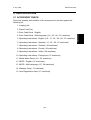
2. PROGRAM MODES
2.1 BASIC OPERATION
1. Component
This copier is equipped with two program modes. One is the Service Program
(SP) Mode for factory and field technician usage, and the other is the User
Program (UP) mode for user usage. Both program modes have a different
access procedure, but all the UP mode functions can be accessed from the
SP mode.
To be able to reset a service call (E5) condition using SP mode, the SP mode
can be accessed while the error condition exists. The error code will not be
displayed in the copy counter during these conditions.
To access these program modes, a certain key must be held down while
turning on the main switch. After accessing, select the required mode number
and perform the necessary procedures needed for that function. It is possible
to move on to the next required mode without exiting each time.
To leave from these modes, turn the main switch off/on.
3. Display
To achieve the same operation for the two models (A183 and A184), the
Magnification Ratio display, the +Zoom key and the –Zoom key are not used.
To display and to distinguish various conditions using the copy counter, the
appearance of the copy counter and the dot (•) which appears in the top left
corner of the Copy Counter is different.
When the Copy Counter is blinking, and the dot is lit, the machine is ready
to accept a program mode number. (The program mode number is
displayed when you input it.)
When the Copy Counter stops blinking, and the dot starts blinking, the
machine is ready to accept an adjustment value, and it may be displaying
the current adjustment value.
4-5
Service
Tables
2. Operation
PROGRAM MODES
4 July 1996
4. Notes
1. With the exception of SP57, all copies made inside the program
modes are made with ID level 3 (center value).
2. Since the Darker/Lighter keys are used during the program modes, image
density cannot be changed using the Darker/Lighter keys while in the
program modes.
3. Since the Copy Counter is used to display the adjustment values and
data, the copy counter can not be displayed.
2.2 SP MODE
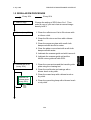
1. Service Program Mode Access Procedure
1. Turn off the main switch.
2. While pressing the Darker key and the Clear/Stop key together, turn on
the main switch.
3. A dot (•) will appear in the top left corner of the Copy Counter.
4. Release the Darker key and the Clear/Stop key, and within 5 seconds,
press the Lighter key (if not pressed within 5 seconds, the machine will
return to the copy mode). The copier is ready to accept the program
number.
NOTE: To access the UP mode, turn on the main switch while pressing the
Clear/Stop key.
2. How to Select the Program Number
1. By using the Increase or Decrease Quantity ("+" or "–") keys, enter the
required program number. At this point, the Copy Counter will be blinking,
and the dot (•) will be lit.
2. When the Lighter key is pressed, the number which is currently blinking in
the Copy Counter will be entered as the selected program number.
4-6
4 July 1996
PROGRAM MODES
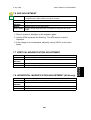
3. Changing the Value of an SP Mode
1. Enter the desired value or setting using the Increase or Decrease
Quantity ("+" or "–") key. For some modes, since the Copy Counter has
only 2 digits, the first digit is displayed in the Manual Image Density
indicator as shown below.
: "1"
For example:
: "252"
: "2"
Copy Counter
A184M500.wmf
NOTE: After changing the value (setting), the previous value (setting)
can be recalled again if the Clear/Stop key is pressed at this
point.
2. When the Lighter key is pressed, the number which is currently displayed
in the Copy Counter will be entered as the new value or setting, and will
be stored in memory.
3. The copier is ready to accept the new program number. Repeat from step
1 or leave SP mode by turning the main switch off/on.
4-7
Service
Tables
: "3"
PROGRAM MODES
4 July 1996
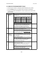
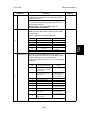
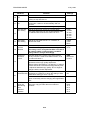
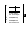
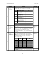
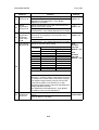
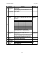
2.3 SP MODE QUICK REFERENCE TABLE
SP Mode
Function
No.
3
Destination Setting
4
Forced Start
Free Run with Exposure Lamp
5
Off
6
Misfeed Detection Off
Free Run
7
8
9
10
11
14
15
16
19
21
23
24
25
26
29
30
31
32
34
35
36
38
*41
*42
*43
*44
SP Mode
Function
No.
*48
Light Intensity Adjustment
49
Fusing Temperature Adjustment
Exposure Lamp Voltage Display
51
52
53
Input Check
Output Check
Scanner Free Run
54
55
All Indicators On
Auto Shut Off Time Setting
Auto Reset Time Setting
57
59
56
60
Count Up/Down Selection
61
Function of Manual ID Level 3
A4 Lengthwise Erase Selection
Total Toner Supply On Time
During Toner Near/End Condition
TD Sensor Sensitivity Setting
Toner Supply ON Time During
Toner Near/End Recovery
Toner Supply OFF Time During
Toner Near/End Recovery
Fusing Temperature Control
Selection
Toner Supply Mode Selection
Toner Supply Amount
(TD Sensor Mode)
Toner Supply Amount
(Fixed Supply Mode)
Image Density Adjustment
Image Adjustment at ID Level 1
Image Bias Adjustment at ID
Level 5
Toner Density Adjustment
Lead Edge Erase Margin
Adjustment
Registration Adjustment
Vertical Magnification Adjustment
Horizontal Magnification
Adjustment
* Items Listed On The Factory Setting Data Sheet
4-8
62
63
64
66
67
69
77
81
82
88
90
91
92
95
96
97
98
99
Fusing Temperature Display
TD Sensor Target Control
Voltage Adjustment
TD Sensor Gain Adjustment
TD Sensor Output Display
ADS Reference Voltage
Adjustment
ADS Output Voltage Display
Optics Temperature Display
Drum Potential Measurement
(With Paper)
Drum Potential Measurement
(Without Paper)
VL Correction Interval
Forced Toner Supply
VR Correction Value
Imaging Unit Check Mode
TD Sensor Initial Output Display
Imaging Unit Counter Display
Auto Shut Off (Energy Star)
Selection
Factory Initialization
Data Communication
Total Copy Counter Display
Factory Data and Counter Clear
Optics Cooling Fan Operation
(120 V (NA) machines only)
Imaging Unit Initialization
Selection
VL Correction Reset
Toner End Force Cancel
Service Call (E5) Reset
Total Counter Clear
Clear All Memory
4 July 1996
PROGRAM MODES
2.4 UP MODE AND SP MODE CROSS REFERENCE TABLE
Function
Image Density Adjustment
Image Adjustment at ID Level 1
Image Bias Adjustment at ID Level 5
Toner Density Adjustment
Auto Shut Off Time Setting
Auto Reset Time Setting
Count Up/Down Selection
Total Copy Counter Display
Imaging Unit Counter Display
VL Correction Interval
Service
Tables
UP Mode No. SP Mode No.
1
34
2
35
3
36
4
38
5
14
6
15
7
16
8
88
9
69
10
62
4-9
PROGRAM MODES
4 July 1996
2.5 SERVICE PROGRAM MODE TABLE
1. In the Function column, comments (extra information) are in italics.
2. In the Settings column, the default value is printed in bold letters.
3. If there is a mark in the Mode No. column, copies can be made within
this SP Mode.
Mode No.
Destination
Setting
3
Forced Start
4
Free Run with
Exposure
Lamp Off
5
Misfeed
Detection Off
6
Function
The setting can be changed depending on the paper
size being used.
No.
Measurement
Copy Count
(SP16 Setting)
0
—
—
—
Note
1
Inch
UP
Factory setting for
120 V copiers
2
Metric
UP
Factory setting for
230 V copiers
This mode does not have any relationship to the
electrical power supply. The erase and magnification
ratio mechanism is changed. For example, by
changing this mode, North American (inch size)
machines can use metric size paper for normal usage.
Selects whether forced start is on or off.
Copy quality and paper transport are not guaranteed.
If forced start is switched on, the copier enters the
ready condition even if the fusing temperature has not
reached the required value yet. Perform this mode
using blank originals only.
A free run is performed without exposure. This mode
can be performed before the fusing unit reaches the
ready temperature.
Press the Start key to start the free run. Press the
C/S key to stop the free run.
This mode is performed with the normal copy process
for LG paper size without the paper feed clutch,
exposure lamp, and total counter increment.
Normally, use SP7 to save toner.
Copies are made without misfeed detection by the
registration and exit sensors.
Press the Start key to make a copy. It stops when
reaching the set count, or when the C/S key is
pressed.
Use this mode to check whether the paper misfeed
was caused by a sensor malfunction.
The total counter increments when copies are
made in this mode.
4-10
Settings
Default = 0
4 July 1996
7
Input Check
Function
Performs a free run with the exposure lamp on. Press
the Start key to start the free run. Press the C/S key
to stop the free run.
This mode is performed with the normal copy process
for LG paper size without the paper feed clutch and
total counter increment.
Before starting, close the platen cover to
minimize toner consumption.
The Manual Image Density indicator is used to
display the input data from the sensors while making
a normal copy.
Press the Start key to perform this mode.
Sensor
8
Manual ID Level Indication Display: Condition
Registration
ID Level 1
ON: Paper Present
Exit
ID Level 2
ON: Paper Present
—
ID Level 3
Scanner HP
ID Level 4
ON: Home Position
—
*Lens/Mirror
HP
ID Level 5
ON: Actuator inside
sensor
*A184 copier only
Output Check
Settings
Use to turn on individual electrical components.
Enter the desired number given in the following table.
Press the Start key to turn on the electrical
component. Press the C/S key to turn off the electrical
component.
Component
No.
1
Electrical Component
Note
Main Motor + Quenching
Lamp + Exhaust Fan Motor
(High Speed)
Charge Corona + Transfer
Corona + Development
Bias Voltage
Dev. bias is the
standard voltage for
manual ID level 3
without corrections.
3
Erase Lamp
All LEDs on
4
Toner Supply Clutch
5
Registration Solenoid
2
9
6
7
Paper Feed Clutch
Main Switch
8
Optics Cooling Fan
9
Exposure Lamp + Optics
Cooling Fan
10
Exhaust Fan Motor
(High Speed)
4-11
Main switch will turn
off when performed.
Standard voltage for
manual ID level 3
without corrections.
Service
Tables
Mode No.
Free Run
PROGRAM MODES
PROGRAM MODES
Mode No.
Scanner Free
10 Run
11
All Indicators
ON
4 July 1996
Function
Starts a scanner free run.
Press the Start key to start the free run. Press the
C/S key to stop the free run.
Turns on all the indicators on the operation panel for
30 seconds. It will turn off automatically after 30
seconds.
14
To turn off the indicators, press the Lighter key.
Selects the auto shut off time in 5 minute steps.
The copier main switch is shut off automatically after
the selected auto shut off time if SP77 is at "0".
Auto Reset
15 Time Setting
Selects an auto reset time of 1 or 3 minutes, or
cancels this mode.
Auto Shut Off
Time Setting
Count
Up/Down
16 Selection
Function of
Manual ID
Level 3
Settings
0: 5 min.
1: 10 min.
2: 15 min.
3: 20 min.
4: 25 min.
5: 30 min.
0: 1 min.
1: 3 min.
2: None
Selects count up or count down.
0: Up
The default setting depends on the setting of SP3. 1: Down
The setting can be changed after SP3 is set, but if
the setting of SP3 is changed again, the SP16
setting will also change accordingly.
Specifies whether the center notch of the manual
density indicator is used as the ADS function, or as
the manual ID level 3.
This mode is used to perform the light intensity
adjustment of the copy quality adjustment.
Always change the setting to 1 at this time, in order to
achieve the center of the manual image density level
to adjust the standard copy quality. Do not forget to
change it back to 0 after adjustment.
A4 Lengthwise Selects the trailing edge erase timing to A4
Erase Selection lengthwise on a machine in which the setting of SP3
(Destination Setting) is set to 1 (inch).
21
Set this to 1 for customers that takes copies of A4
paper occasionally without changing the magnification
ratio.
Total Toner
Selects the toner supply clutch on time performed
Supply On
after every copy job under the toner near/end
Time During
condition.
23
Toner
Near/End
Condition
0: ADS
1: Manual ID
Level 3
19
4-12
0: LT
1: A4
0: 5 s.
1: 10 s.
2: 15 s.
3: 20 s.
4: 25 s.
5: 30 s.
4 July 1996
24
Toner Supply
ON Time
25 During Toner
Near/End
Recovery
Toner Supply
OFF Time
26 During Toner
Near/End
Recovery
Fusing
Temperature
29
Control
Selection
Function
Adjusts the sensitivity of the TD sensor.
SP Setting
Sensitivity (V/wt%)
0
0
1
0.05
2
0.10
↓
↓
7
0.35
8
0.40
9
0.45
10
0.50
11
0.55
↓
↓
19
0.95
20
1.00
Settings
Default = 8
Note
0.05 per step
Default
0.05 per step
The toner supply clutch on time and/or the toner
density are changed by this setting. See "Detailed
Descriptions - Toner Supply Control" for more details.
The ON/OFF movement of the toner supply clutch is 0 ~ 40
changed after the TD sensor voltage level recovers to Default = 7
level 6 or less. This mode changes the ON time.
(0.1 second per step [range: 0 to 4 seconds])
Normally, this value should not be changed.
The ON/OFF movement of the toner supply clutch is
changed after the TD sensor voltage level recovers to
level 6 or less. This mode changes the OFF time.
(0.1 second per step [range: 0 to 4 seconds])
Normally, this value should not be changed.
Selects the fusing temperature control mode.
After selecting the control mode and turning the main
switch off/on, the fusing temperature control mode is
changed.
4-13
0 ~ 40
Default = 33
0: ON/OFF
control
1: Phase
control
Service
Tables
Mode No.
TD Sensor
Sensitivity
Setting
PROGRAM MODES
PROGRAM MODES
Mode No.
Toner Supply
Mode
Selection
4 July 1996
Function
Selects the toner supply system.
Normally, this value should not be changed.
SP
Setting
Detect supply mode using
the initial TD sensor
setting.
1
Detect supply mode using
the target TD sensor
voltage set with SP53.
2
Detect supply mode (fixed
amount) using the initial
TD sensor setting.
3
Detect supply mode (fixed
amount) using the target
TD sensor voltage set with
SP53.
32
Default
Fixed supply mode.
4
Toner Supply
Amount
(Fixed
Supply Mode)
Note
0
30
Toner Supply
Amount
(TD Sensor
31 Mode)
Toner Supply System
Settings
Default = 0
Use only in abnormal TD
sensor conditions.
See SP31/SP32 for the toner supply amount.
Determines how much toner is supplied in detect
supply mode.
Select the base unit for toner supply time from 0.1 s
to 5.0 s in 0.1 s steps. The multiple of this unit that is
used depends on current TD sensor output.
See "Detailed Descriptions-Toner Supply Control" for
more details.
Determines how much toner is supplied in fixed
supply mode and in detect supply (fixed amount)
mode.
For example, if the user normally makes copies of A4
originals that are about 7% black, select the 7%
setting for best results.
SP
Setting
Ratio
Supply Time
0
3.5%
0.3 s
1
7.0%
0.6 s
2
15%
1.2 s
3
30%
2.4 s
4
45%
3.6 s
5
60%
4.8 s
6
—
∞
Continuous supply
7
0%
0
No toner supply
Note
Default
See "Detailed Descriptions-Toner Supply Control" for
more details.
4-14
1 ~ 50
Default = 1
(0.1 s)
0~7
Default =0
PROGRAM MODES
Mode No.
Function
Image Density Selects the image density level in ADS and manual ID
Adjustment
mode.
The development bias and the exposure lamp data
are increased or decreased. This adjustment affects
ADS mode and all manual ID settings.
34
SP Setting
Setting
Dev. Bias
0
Normal
0
Exposure Lamp
0
1
Light
–40 V
0
2
Dark
+40 V
0
3
Lighter
–40 V
+3 steps
4
Darker
+40 V
–3 steps
5
Lightest
–40 V
+7 steps
6
Darkest
+40 V
–7 steps
Settings
0: Normal
1: Light
2: Dark
3: Lighter
4: Darker
5: Lightest
6: Darkest
The exposure lamp setting specifies the change
relative to the base exposure lamp voltage (Vo) in
SP48, 1 step of the lamp voltage equals 0.5 V for 120
V (NA), and 1.0 V for 230 V (EU) machines.
Image
Adjustment at
ID Level 1
35
Adjusts the image density at ID level 1 by changing
the exposure lamp voltage.
SP Setting
Setting
Exposure
Lamp
Note
0
Normal
–6 steps
Default
1
Darker
–8 steps
2
Darkest
–10 steps
0: Normal
1: Darker
2: Darkest
This setting specifies the change relative to the base
exposure lamp voltage Vo (SP48). 1 step of the lamp
voltage equals 0.5 V for 120 V (NA), and 1.0 V for
230 V (EU) machines.
Image Bias
Adjustment at
36 ID Level 5
Toner Density
Adjustment
Adjusts the development bias voltage used at ID level 0: Normal
5
1: Lighter
2: Lightest
0: Bias –40 V
1: Bias –80 V
2: Bias –120 V
Adjusts copy quality by changing the toner
concentration inside the development unit.
38
Lead Edge
Erase Margin
41 Adjustment
Adjusts the lead edge erase margin.
0.5 mm per step (–4.0 mm to +3.5 mm).
See "Replacement and Adjustment - Copy Quality
Adjustment" for details.
4-15
0: Normal
1: Darker
2: Lighter
3: Darkest
4: Lightest
0 ~ 15
Default = 8
(2.5 mm from
the leading
edge)
Service
Tables
4 July 1996
PROGRAM MODES
42
Mode No.
Registration
Adjustment
Vertical
Magnification
43
Adjustment
Horizontal
Magnification
44 Adjustment
(A184 copier
only)
Light Intensity
Adjustment
4 July 1996
Function
Adjusts the registration.
0.5 mm per step (–4.0 mm to +3.5 mm). See
"Replacement and Adjustment - Copy Quality
Adjustment" for details.
Adjusts magnification in the paper travel direction by
changing the scanner speed.
0.2% per step (–3.2% to +3.0%). See "Replacement
and Adjustment - Copy Quality Adjustment" for details.
Adjusts magnification perpendicular to the direction of
paper travel, by changing the home position of the
lens and mirrors.
0.2% per step (–3.2% to +3.0%). See "Replacement
and Adjustment - Copy Quality Adjustment" for details.
Adjusts the exposure lamp voltage.
Lamp Voltage (V)
SP Setting
48
Fusing
Temperature
49
Adjustment
120 V (NA) Version
230 V (EU) Version
100
50.0
100
101
50.5
101
102
51.0
102
↓
↓
↓
150
75.0
150
↓
↓
↓
180
90.0
180 Max
↓
↓
—
193
96.5
—
194
97.0 Max
—
Settings
0 ~ 15
Default = 8
0 ~ 31
Default = 16
0 ~ 31
Default = 16
120 V
Machines
100~194
Default = 137
230 V
Machines
100~180
Default = 128
Before performing this mode, clean the optics and
clear the VL correction (SP95). Open SP34 and return
the setting to the normal value if it has been changed.
Then adjust the light intensity using an OS-A4 Test
Chart with the platen cover placed over it. After
adjusting the light intensity, adjust the ADS Reference
Voltage Adjustment (SP56).
See "Replacement and Adjustment - Copy Quality"
for details on how to do this adjustment.
Adjusts the control temperature of the hot roller during 175 ~ 195°C
copying.
Default=185°C
175°C to 195°C in 1°C steps.
4-16
4 July 1996
Mode No.
Exposure
Lamp Voltage
Display
PROGRAM MODES
Function
Displays the current exposure lamp voltage.
For 120V machines, the actual applied
voltage = displayed value/2
Settings
0 ~ 225 V
The exposure lamp turns on for 10 seconds when this
mode is selected. Do not repeat more than 5 times, to
avoid overheating the optics cavity.
The Manual Image Density indicator is used to
display the first digit.
Fusing
Displays the fusing temperature detected by the
Temperature
fusing thermistor.
Display
Press the Start key to monitor the temperature during
52
the normal copy cycle.
The Manual Image Density indicator is used to
display the first digit.
TD Sensor
If the setting of SP30 (Toner Supply Mode Selection) 1 ~ 200
Target Control is 1 or 3, this value is used for the TD sensor target
Default = 97
53
Voltage
voltage.
(0.02 V per
Adjustment
step)
TD Sensor
When the TD Sensor initial setting is performed, this
0 ~ 255
Gain
mode is adjusted automatically.
Default = 153
54
Adjustment
(0.04 V per
Normally, this value should not be changed.
step)
Displays the TD sensor output voltage.
TD Sensor
Output Display Press the Start key to monitor the output voltage
during the normal copy cycle.
The output voltage will display "0" when this mode is
55
accessed after turning on the main switch without
making any copies.
The Manual Image Density indicator is used to
display the first digit.
56
ADS
Reference
Voltage
Adjustment
Adjusts the ADS reference voltage.
After adjusting the light intensity (SP48), place 5
sheets of A4 (LT) white paper on the exposure glass
and select this mode. Adjust the ADS voltage to 2.5 ±
0.2 V using VR100 on the main control board. The
Manual Image Density indicator is used to display
the first digit. See "Replacement and Adjustment Copy Quality Adjustment" for details.
ADS Output
Displays the ADS output voltage.
Voltage Display Press the Start key to monitor the output voltage
during the normal copy cycle.
57
For only this SP mode, the copies are made with the
ADS mode (other SP modes use the manual ID level
3). The Manual Image Density indicator is used to
display the first digit.
4-17
(0.02 V per
step)
Service
Tables
51
PROGRAM MODES
Mode No.
Optics
Temperature
59
Display
4 July 1996
Function
Displays the optics temperature detected by the
optics thermistor.
Settings
Press the Start key to monitor the temperature during
the normal copy cycle.
Drum Potential Factory use only.
60 Measurement
(With Paper)
Drum Potential Factory use only.
61 Measurement
(Without Paper)
VL Correction Sets the interval for VL correction. The exposure lamp 0 ~ 8
Interval
voltage (SP48) is increased by 1 step at the set copy Default = 0
count interval.
62
SP Setting
Exposure Lamp
Note
0
+1 step/1500 copies
Default
1
+1 step/1000 copies
2
+1 step/2000 copies
3
+1 step/500 copies
4
+1 step/2500 copies
5
+1 step/250 copies
6
+1 step/3000 copies
7
+1 step/4000 copies
8
No Correction
1 step of the lamp voltage equals 0.5 V for
N-American, and 1.0 V for European machines.
Forced Toner
Supply
Forces the toner bottle to supply toner to the
development unit.
This mode starts when the Start key is pressed,
and stops automatically after the selected time.
Use this mode to achieve standard image density
when copy quality problems indicate low toner.
0: 6 seconds
1: 3 seconds
VR Correction
Value
Sets the VR correction value.
Keep this at the default setting.
Factory use only.
Default = 0
Displays the TD sensor initial setting output.
The Manual Image Density indicator is used to
display the first digit.
(0.02 V per
step)
63
64
Imaging Unit
Check Mode
TD Sensor
67 Initial Output
Display
66
4-18
4 July 1996
Mode No.
Imaging Unit
Counter
Display
PROGRAM MODES
Function
Shows the total number of copies made by the
Imaging Unit installed in the machine.
Settings
The counter is displayed as shown in the example
below. To view the next two digits, press the Darker
key.
For example: The copy count is 21548
Manual ID Indicator
Copy Counter
Auto Shut Off
77 (Energy Star)
Selection
81
82
Factory
Initialization
Data
Communication
Total Copy
Counter
Display
Selects the "Automatic Shut Off" mode.
The copier automatically shuts itself off at the auto
shut off time selected (SP14).
Factory use only.
Factory use only.
Displays the total (electrical) copy counter.
The counter is displayed as shown in the example
below. To view the next two digits, press the Darker
key.
For example: The total copy count is 1087
Manual ID Indicator Copy Counter
88
The mechanical total counter and the electrical
total counter may not always display the same
value, because of initial differences in the counter
values.
4-19
0: Yes
1: No
Service
Tables
69
PROGRAM MODES
Mode No.
Factory Data
90 and Counter
Clear
Optics Cooling
Fan Operation:
91
120 V (NA)
machines only
Imaging Unit
Initialization
Selection
92
VL Correction
Reset
95
4 July 1996
Function
Settings
Factory use only.
Not used. Keep the default setting.
0: No
1: Yes
For testing purposes only: Selects whether the
Imaging Unit initialization procedure is performed
when a new Imaging Unit is installed.
Set this mode to 1 when you wish to check the
copier condition with a new Imaging Unit, without
the settings being changed by the Imaging Unit
initialization procedure. After using this mode, do
not forget to change the setting back to YES.
If the setting was not changed before the SP
mode was closed, the ID indicator will blink.
0: Yes
1: No
Resets the exposure lamp data and counter for the VL 0: No
correction. To clear, enter "1" and press the Lighter
1: Yes
key and the Darker key at the same time.
Before performing this mode, clean the optics parts.
After performing this mode, do SP48 then SP56. See
page 4-2 for details.
Toner End
96 Force Cancel
The Toner End condition is canceled forcibly.
By pressing the Lighter key to enter this SP mode, the
toner end condition is canceled.
Service Call
Resets a service call (E5) condition.
97 (E5) Condition Turn the main switch off and on to check if the service
Reset
call condition is reset.
Total Counter Clears the total (electrical) counter.
Clear
Normally, this SP mode should not be performed.
To clear, enter "1" and press the Lighter key and the
98
Darker key at the same time.
To avoid resetting the counter by mistake, the counter
is reset only when the Lighter key and the Darker key
are pressed at the same time.
Clear All
Clears all counters and returns all modes to the
Memory
default settings. See the Clear All Memory Procedure
in this section for more details.
Normally, this SP mode should not be performed.
This SP mode is required only when replacing the
EEPROM, or when the copier malfunctions due to a
99
damaged EEPROM.
To clear, enter "1" and press the Lighter key and the
Darker key at the same time.
To avoid resetting the memory by mistake, the
memory is reset only when the Lighter key and the
Darker key are pressed at the same time.
4-20
0: No
1: Yes
0: No
1: Yes
4 July 1996
PROGRAM MODES
2.6 CLEAR ALL MEMORY PROCEDURE
CAUTION
The Clear All Memory procedure (SP99) resets all the correction data
for copy process control and all the software counters, and returns all
modes and adjustments to the default settings.
Normally, this SP mode should not be performed.
This procedure is required only when replacing the EEPROM or when
the copier malfunctions due to a damaged EEPROM.
1. Enter SP99.
2. Enter "1".
NOTE: To avoid resetting the memory by mistake, the memory is reset
only when the Darker key and the Lighter key are pressed at the
same time.
4. Turn the main switch off and on.
– Recovering the machine after a memory reset –
CAUTION
If SP99 is performed, all the software counters for process control and
the TD sensor initial setting data are reset. As a result, the old drum
and the old developer cannot be used any more. Otherwise, dirty
background and/or toner scattering will appear on copies sooner or
later because proper process control will not be applied to the drum.
After doing SP99, execute the following procedure to return the
machine to its normal operating condition.
1. Clean the optics and inside the copier if necessary.
2. Install a new imaging unit and turn on the main switch. (The machine will
perform the TD sensor initial setting automatically.)
3. Refer to the "SP MODE FACTORY SETTING DATA" sheet located
behind the sub operation panel cover and enter the data that were stored
in the following SP modes at the factory.
• SP41: Lead Edge Erase Margin
• SP42: Registration Adjustment
• SP43: Vertical Magnification Adjustment
• SP44: Horizontal Magnification Adjustment
• SP48: Light Intensity Adjustment
4-21
Service
Tables
3. Press the Darker key and the Lighter key at the same time.
PROGRAM MODES
4 July 1996
4. Open SP3 (Destination Setting), and enter the setting according to the
customer’s environment.
5. Check the copy quality and the paper path and do any necessary
adjustment (see Replacement and Adjustment - Copy Quality
Adjustments).
4-22
4 July 1996
SERVICE TABLES
3. SERVICE TABLES
3.1 TEST POINTS (Main Control Board)
Number
TP101
Label
(T. OUT)
Monitored Signal
Toner density sensor output
Number
VR100
VRT
VRB
VRG
Location
Main Control Board
High Voltage Supply Board - CT/B/G
High Voltage Supply Board - CT/B/G
High Voltage Supply Board - CT/B/G
4-23
Function
Change the ADS voltage
(2.5 ± 0.2 volts)
Change the charge and transfer
corona voltage
Changes the standard development
bias voltage
Changes the charge grid voltage
Service
Tables
3.2 VARIABLE RESISTORS
SECTION 5
PREVENTIVE MAINTENANCE
4 July 1996
PREVENTIVE MAINTENANCE SCHEDULE
1. PREVENTIVE MAINTENANCE SCHEDULE
1.1 PM TABLE
NOTE: The amounts mentioned as the PM interval indicate the number of
copies.
Symbol key: L: Lubricate R: Replace C: Clean I: Inspect A: Adjust
Optics
Reflector
1st to 5th Mirrors
6th Mirror
Lens
Exposure Glass
Platen Cover Sheet
Scanner Guide Rod
Scanner Guide Rail
4th/5th Mirror Guide Rod
4th/5th Mirror Guide Rail
Around Drum
Transfer Corona Unit
Transfer Guide Plate
End Blocks and Casings
Erase Lamp
QL
Paper Feed
Pick-up Roller
30 k
60 k
C
C
C
C
C
C
C
C
C
C
C
C
C
C
C
C
C
C
C
C
C
C
C
C
C
C
L
L
L
L
L
L
L
L
L
L
L
L
Silicone cloth
Silicone cloth
Blower brush
Blower brush
Soft cloth dampened with
alcohol or water
Soft cloth dampened with
water
Launa oil
G501
G501 (Lubricate if necessary)
G501
C
C
C
C
C
C
C
R
C
C
C
C
C
C
C
C
C
R
C
C
C
C
Cleaning tool
Cleaning tool
Blower brush or dry cloth
Blower brush or dry cloth
Blower brush or dry cloth
C
C
C
R
C
C
C
C
C
C
C
C
C
C
C
C
C
C
C
C
C
C
C
C
R
R
C
C
R
R
R
L
Bottom Plate Pad
Relay Roller
Registration Roller
Paper Feed Guide
Fusing
Hot Roller
Pressure Roller
Stripper Pawls
90 k 120 k
5-1
Notes
Soft cloth dampened with
water
Soft cloth dampened with
water
Soft cloth dampened with
water
Soft cloth dampened with
water
Soft cloth dampened with
water
Suitable solvent
Preventive
Maintenance
EM
PREVENTIVE MAINTENANCE SCHEDULE
EM
Fusing Entrance and Exit
Guide Plates
Fusing Thermistor
Others
ADS
Exit and
Registration Sensors
Bearings
Ozone Filter
4 July 1996
30 k
60 k
90 k 120 k
C
C
C
C
C
C
C
C
Notes
Suitable solvent
Suitable solvent
Adjust when the lamp voltage
is changed.
A
I
R
I
R
5-2
I
R
I
R
4 July 1996
PREVENTIVE MAINTENANCE SCHEDULE
1.2 REGULAR PM PROCEDURE
Every 30 k
1. Make a copy
2. Optics (every 30 k)
Every 60 k
Change the setting of SP19 from 0 to 1. Then
make a copy of your test chart at manual image
density level 3.
1. Clean the reflector and 1st to 5th mirrors with
a silicone cloth.
2. Clean the 6th mirror and lens with a blower
brush.
3. Clean the exposure glass with a soft cloth
dampened with alcohol or water.
4. Clear the platen cover sheet with a soft cloth
dampened with water.
6. Lubricate the scanner guide rail and the
4th/5th mirror guide rail with G501.
3. Around the drum
(every 30 k)
1. Clean the corona wires and the transfer guide
plate using the cleaning tool.
2. Clean the end blocks and casings with a
blower brush or dry cloth.
Replace the
corona wires
(every 60 k)
3. Clean the erase lamp with a blower brush or
dry cloth.
4. Clean the quenching lamp with a blower brush
or dry cloth.
5-3
Preventive
Maintenance
5. Lubricate the scanner guide rod with Launa oil.
PREVENTIVE MAINTENANCE SCHEDULE
4. Paper Feed
(every 30 k)
4 July 1996
1. Clean the pick-up rollers with a soft cloth
dampened with water. (Replace at every 90 k.)
2. Clean the bottom plate pad with a soft cloth
dampened with water.
3. Clean the relay roller and the registration
roller with a soft cloth dampened with water.
4. Clean the paper feed guide with a soft cloth
dampened with water.
5. Fusing Unit
(every 30 k)
1. Clean the stripper pawls with a suitable
solvent. (Replace at every 120 k.)
2. Clean the fusing entrance and exit guide
plates with a suitable solvent.
3. Clean the fusing thermistor with a suitable
solvent.
Fusing Unit
(every 60 k)
6. Others (every 30 k)
1. Replace the hot roller.
2. Replace the pressure roller.
1. Replace the ozone filter.
2. Inspect the exit and registration sensors.
3. Inspect the bearings.
7. Copy Quality
1. Reset the VL correction (SP95).
2. Make a copy of a test chart at manual image
density level 3. Perform the light intensity
adjustment (SP48) if necessary.
3. Return the setting of SP19 from 1 to 0.
4. Perform the ADS reference voltage
adjustment (SP56).
5-4
4 July 1996
SPECIAL TOOLS AND LUBRICANTS
2. SPECIAL TOOLS AND LUBRICANTS
Description
Scanner Positioning Pin (2 pcs/set)
Test Chart - OS-A4 (10 pcs/set)
Launa OIl
Silicone Grease G-510
Digital Multimeter
Setting Powder
Q’ty
1
1
1
1
1
1
Preventive
Maintenance
Part Number
A184 9501
5214 9500
5442 9103
5203 9501
5420 9507
5442 9101
5-5
SECTION 6
REPLACEMENT
AND
ADJUSTMENT
4 July 1996
EXTERIOR
1. EXTERIOR
1.1 OPERATION PANEL POSITION CHANGE
[B]
[C]
[D]
[A]
1. Remove the operation panel [A] (1 screw and 2 connectors).
2. Connect the 2 connectors [B] and [C].
3. Remove the side cover [D] (1 screw).
4. Install the side cover [D] at the other position (1 screw).
5. Connect the two connectors of the operation panel, then set the operation
panel and secure it with the screw removed in step 1.
6-1
Replacement
Adjustment
A184R500.wmf
EXTERIOR
4 July 1996
1.2 PLATEN COVER POSITION CHANGE
[B]
[A]
A184R536.wmf
A184R537.wmf
[C]
A184R538.wmf
1. Hold the platen cover [A] as shown and pull it in the direction of the arrow.
2. Remove the two caps [B] from the main body. Then fix the caps over the
slots where the platen cover was set.
3. Put one of the hinges [C] into one of the openings in the copier. Then fix
the hinge to the platen cover and lean the cover back until it clicks.
4. Attach the other hinge to the platen cover. Hold the platen cover and
lower the hinge into the opening. Then push the hinge into the opening
with your finger until it locks in position.
6-2
4 July 1996
EXTERIOR
1.3 EXTERIOR COVER/EXPOSURE GLASS REMOVAL
[C]
[B]
[A]
[D]
1. Remove the operation panel [A] (1 screw and 2 connectors), side cover
[B], and the platen cover.
2. Remove the upper cover [C] (4 screws).
3. Remove the exposure glass [D].
NOTE: When removing or reinstalling the upper cover, take care not to
hook the harness onto the projections inside the cover.
6-3
Replacement
Adjustment
A184R501.wmf
EXTERIOR
4 July 1996
1.4 UPPER UNIT STOPPER RELEASE
[C]
[A]
[E]
[B]
[G]
[F]
[D]
[G]
A184R502.wmf
1. Remove the upper cover. (See Exterior Cover/Exposure Glass Removal.)
2. Remove the exposure glass.
3. Release the stopper and open the upper unit [A].
4. Remove the snap ring [B] and remove the pin [C] to release the arm [D].
5. While holding the upper unit, remove the snap ring [E] and release the
arm [F] from the pin.
NOTE: If the upper unit is opened more than 90 degrees, the exterior
cover of the lower unit might be damaged.
6. To keep the position of the upper unit, fix the arm [D] to position [G] with
the pin and snap ring removed in step 4.
6-4
4 July 1996
OPTICS
2. OPTICS
2.1 1ST SCANNER REMOVAL
[E]
[F]
[D]
[C]
[H]
[A]
[B]
[G]
A184R503.wmf
A184R504.wmf
1. Remove the upper cover and the exposure glass. (See Exterior
Cover/Exposure Glass Removal.)
NOTE: Move the 1st scanner by holding the scanner belt [B]. Handling
the 1st scanner will deform the frame.
3. Disconnect the connectors [C] and [D] and the clamps.
4. Remove the 1st scanner (2 screws [E]).
- Reinstallation 1. Set the 1st scanner with 2 screws [E]. (Do not fully tighten the screws.)
2. Slide the 1st scanner to the home position and insert the two positioning
pins [F].
NOTE: Scanner positioning pins are available as a service part.
P/N: A184 9501 (See the parts catalog.)
3. Connect the two connectors [G] and [H] and secure the harness to the
clamps.
4. Tighten the two screws [E] to secure the 1st scanner.
5. Install the exposure glass and exterior covers. Then, check the image
quality.
6-5
Replacement
Adjustment
2. Slide the 1st scanner [A] about 100 mm towards the direction of the arrow.
OPTICS
4 July 1996
2.2 2ND MIRROR REPLACEMENT
[E]
[B]
[D]
[C]
[A]
A184R505.wmf
1. Remove the upper cover and the exposure glass. (See Exterior
Cover/Exposure Glass Removal.)
2. Slide the 1st scanner about 200 mm from the home position.
NOTE: Move the 1st scanner by holding the scanner belt. Handling the
1st scanner will deform the frame.
3. Remove the spring plate [A] securing the 2nd mirror [B].
4. Slide the 2nd mirror and remove the spring plate [C].
5. Remove the 2nd mirror.
- Reinstallation 1. Cut off both ends of the protection sheet covering the new 2nd mirror.
2. Put the ends of the 2nd mirror into the cutouts in the 2nd scanner bracket.
NOTE: Make sure that the reflecting surface faces the lens.
3. While holding the mirror, set one spring plate [C]. Then set the other
spring plate [A].
NOTE: 1) Make sure that the notches [D] in the spring plates are correctly
set at position [E].
2) Do not touch the reflecting surface with bare hands.
6-6
4 July 1996
OPTICS
2.3 3RD MIRROR REPLACEMENT
[D]
[A]
[B]
[C]
A184R506.wmf
A184R507.wmf
1. Remove the upper cover and the exposure glass. (See Exterior
Cover/Exposure Glass Removal.)
2. Slide the 1st scanner about 200 mm from the home position.
NOTE: Move the 1st scanner by holding the scanner belt. Handling the
1st scanner will deform the frame.
3. Remove the 1st scanner. (See 1st Scanner Removal.)
5. Remove the 3rd mirror [B]. (Refer to steps 3 to 5 of 2nd Mirror Removal.)
- Reinstallation 1. Install the 3rd mirror on the 2nd scanner unit. (Refer to - Reinstallation of 2nd Mirror Replacement.)
2. Put back the two screws [C]. (Do not fully tighten the screws.)
3. Slide the 2nd scanner unit to the home position and insert the two
positioning pins [D].
NOTE: Scanner positioning pins are available as a service part.
P/N: A184 9501 (See the parts catalog.)
4. Tighten the 2 screws to fix the 2nd scanner position.
5. Install the 1st scanner. (Refer to 1st Scanner Removal.)
6. Install the exposure glass and exterior covers. Then, check the image
quality.
6-7
Replacement
Adjustment
4. Remove the 2nd scanner [A] (2 screws [C]).
OPTICS
4 July 1996
2.4 LENS AND 4TH/5TH MIRROR POSITION ADJUSTMENT
(A184 model only)
[A]
[B]
[C]
A184R547.wmf
[D]
A184R509.wmf
1. Remove the exterior covers and the exposure glass. (See Exterior
Cover/Exposure Glass Removal.)
2. Remove the lens cover [A] (1 screw).
3. Insert the two positioning pins [B]. If the pins cannot be inserted, loosen
the screw [C] and adjust the lens unit position.
NOTE: 1) Use the timing belt [D] to move the lens unit.
2) Scanner positioning pins are available as a service part.
P/N: A184 9501 (See the parts catalog.)
6-8
4 July 1996
OPTICS
2.5 4TH MIRROR REMOVAL
[B]
[A]
[E]
[D]
[C]
A184R510.wmf
1. Remove the exterior covers. (See Exterior Cover/Exposure Glass
Removal.)
2. Remove the support plate [A] (2 screws).
3. Remove the lens cover [B] (1 screw).
4. Remove the 4th mirror bracket [C] (1 spring and 1 screw).
5. Remove the 4th mirror [D]. (Refer to steps 3 to 5 of 2nd Mirror Removal.)
NOTE: When reinstalling the screw [E], do not tighten it strongly.
Otherwise, the frame will bend.
6-9
Replacement
Adjustment
A184R508.wmf
OPTICS
4 July 1996
2.6 5TH MIRROR REMOVAL
[B]
[C]
[A]
A184R508-2.wmf
A184R511.wmf
[D]
A184R512.wmf
A184R513.wmf
1. Remove the exterior covers. (See Exterior Cover/Exposure Glass
Removal.)
2. Remove the support plate [A] (2 screws).
3. Remove the lens cover [B] (1 screw).
4. Remove the lens unit base [C] (5 screws and 2 connectors).
NOTE: 1) Do not touch the mirror surface or lens with bare hands.
2) Place the lens unit base on a soft cloth, so as not to damage
the 6th mirror.
5. Turn the lens unit base upside down. Then remove the 5th mirror [D].
(Refer to steps 3 to 5 of 2nd Mirror Removal.)
NOTE: Before turning the lens unit base over, confirm that the lens unit
is in the home position. Otherwise, the lens unit will drop.
6-10
4 July 1996
OPTICS
2.7 LENS AND MIRROR MOTOR REMOVAL
[B]
[C]
[A]
A184R511-2.wmf
A184R508-3.wmf
A184R512-2.wmf
A184R539.wmf
1. Remove the exterior covers. (See Exterior Cover/Exposure Glass
Removal.)
2. Remove the support plate [A] (2 screws).
3. Remove the lens cover [B] (1 screw).
4. Remove the lens unit base [C] (5 screws and 2 connectors).
NOTE: 1) Do not touch the mirror surface or lens with bare hands.
2) Place the lens unit base on a soft cloth, so as not to damage
the 6th mirror.
5. Turn the lens unit base upside down. Then remove the lens and mirror
motor [D] (2 screws).
NOTE: Before turning the lens unit base over, confirm that the lens unit
is in the home position. Otherwise, the lens unit will drop.
6-11
Replacement
Adjustment
[D]
IMAGING UNIT
4 July 1996
3. IMAGING UNIT
3.1 IMAGING UNIT REMOVAL
[B]
[A]
[C]
A184R515.wmf
1. Open the upper unit.
2. Pull up the imaging unit [A], releasing the projections [B] from the hooks
[C].
NOTE: 1) Be careful not to damage the drum surface.
2) Do not touch the drum surface with bare hands.
3. After removing the imaging unit from the main body, cover the unit with
sheets of paper to prevent the drum from being exposed.
6-12
4 July 1996
IMAGING UNIT
3.2 CHARGE CORONA UNIT REMOVAL
[A]
A184R516.wmf
2. Remove the charge corona unit [A] (1 screw).
NOTE: When removing the charge corona unit, be careful not to scratch
the drum surface.
6-13
Replacement
Adjustment
1. Remove the imaging unit. (See Imaging Unit Removal.)
IMAGING UNIT
4 July 1996
3.3 CLEANING BLADE REPLACEMENT
[A]
A184R535.wmf
1. Remove the imaging unit. (See Imaging Unit Removal.)
2. Remove the charge corona unit. (See Charge Corona Unit Removal.)
3. Replace the cleaning blade [A] (2 screws).
NOTE: 1) When removing the cleaning blade, be careful not to scratch
the drum surface.
2) When installing a new cleaning blade, apply setting powder on
the edge of the cleaning blade.
6-14
4 July 1996
PAPER FEED
4. PAPER FEED
4.1 PAPER FEED CLUTCH REPLACEMENT
[A]
[C]
[B]
1. Open the upper unit.
2. Remove the imaging unit. (See Imaging Unit Removal.)
3. Replace the paper feed clutch [A] (1 connector, 1 snap ring, and a spring).
NOTE: When reinstalling a new clutch, engage the notch [B] with the
stopper [C].
6-15
Replacement
Adjustment
A184R517.wmf
PAPER FEED
4 July 1996
4.2 PAPER FEED ROLLER REMOVAL
[A]
[B]
[C]
A184R518.wmf
1. Open the upper unit.
2. Remove the imaging unit. (See Imaging Unit Removal.)
3. Remove the paper feed tray.
4. Remove the paper feed clutch [A]. (See Paper Feed Clutch Removal.)
5. Remove the securing spring plate [B].
6. Slide the paper feed roller assembly [C] to the rear side, then pull down to
remove it (arrow direction).
NOTE: Do not touch the roller with bare hands.
- Reinstallation 1. Set the paper feed roller assembly so that the flat side of the semicircular
feed rollers faces down.
2. Slide the paper feed roller assembly to the front side until it clicks.
6-16
4 July 1996
PAPER FEED
4.3 REGISTRATION SOLENOID REPLACEMENT
[C]
[D]
[E]
[F]
[B]
[A]
NOTE: When replacing the registration solenoid [A], the plunger spring [B]
should be replaced.
1. Open the upper unit.
2. Remove the imaging unit. (See Imaging Unit Removal.)
3. Remove the paper feed tray.
4. Remove the harness cover [C] (2 screws).
5. Disconnect the connector [D].
6. Remove the registration solenoid cover [E] (2 screws).
7. Remove the stopper [F].
8. Replace the registration solenoid and the plunger spring.
NOTE: 1) When reinstalling the registration solenoid, make sure that the
harness side of the solenoid is facing upwards.
2) When reinstalling the new plunger spring, make sure not to
stretch it by more than 21.0 mm.
6-17
Replacement
Adjustment
A184R819.wmf
FUSING
4 July 1996
5. FUSING
5.1 FUSING UNIT REMOVAL
[A]
A184R520.wmf
1. Remove the upper cover and the exposure glass. (See Exterior
Cover/Exposure Glass Removal.)
2. Release the upper unit stopper. (See Upper Unit Stopper Release.)
3. Remove the fusing unit [A] (4 screws and 3 connectors).
6-18
4 July 1996
FUSING
5.2 PRESSURE ROLLER REPLACEMENT
[A]
[C]
[B]
A184R522.wmf
NOTE: When reinstalling, make sure both right and left fusing arms are
positioned correctly as shown above.
1. Release the upper unit stopper. (See Upper Unit Stopper Release.)
2. Remove the fusing upper unit [A] (4 screws).
3. Remove the pressure roller [B] with the two bearings [C].
4. Replace the pressure roller.
NOTE: Do not touch the pressure roller surface with bare hands.
6-19
Replacement
Adjustment
A184R521.wmf
FUSING
4 July 1996
5.3 FUSING LAMP REPLACEMENT
[B]
[A]
[C]
A184R523.wmf
1. Open the upper unit.
2. Remove the front and rear lamp holders [A] and [B] (1 screw each).
3. Disconnect the three connectors, and replace the fusing lamp [C].
NOTE: 1) Do not touch the fusing lamp with bare hands.
2) When installing a new fusing lamp, set the fusing lamp
connectors correctly as shown in the illustration.
3) Make sure that both fusing lamp insulators are properly set in
the holders.
6-20
4 July 1996
FUSING
5.4 FUSING EXIT PAWL REPLACEMENT
[A]
[D]
A184R521.wmf
[B]
A184R524.wmf
1. Release the upper unit stopper. (See Upper Unit Stopper Release.)
2. Remove the fusing upper unit [A] (4 screws and 2 connectors).
3. Remove the fusing exit guide [B] (2 screws).
4. Remove the fusing exit pawl bracket [C] (2 screws).
5. Replace the fusing exit pawls [D] (1 spring each).
6-21
Replacement
Adjustment
[C]
FUSING
4 July 1996
5.5 HOT ROLLER REPLACEMENT
[A]
[E]
[F]
A184R521.wmf
[C]
[D]
[B]
A184R525.wmf
1. Release the upper unit stopper. (See Fusing Unit Removal.)
2. Remove the fusing upper unit [A] (4 screws and 2 connectors).
3. Remove the fusing lamp. (See Fusing Lamp Replacement.)
4. Remove the fusing exit guide [B] (2 screws).
5. Remove the fusing exit pawl bracket [C] (2 screws).
6. Remove the front [D] and rear [E] C-rings. Then replace the hot roller [F].
NOTE: 1) The shape of the left C-ring [D] is different from the right C-ring
[E]. The ends of the left C-ring are bent as shown.
2) When reinstalling the exit pawls, be careful not to scratch the
hot roller surface.
3) When reinstalling the fusing exit guide, be careful not to
damage the exit sensor.
4) Do not touch the hot roller surface with bare hands.
6-22
4 July 1996
FUSING
5.6 FUSING THERMISTOR REPLACEMENT
[A]
A184R526.wmf
1. Remove the fusing exit pawl bracket (2 screws). (Follow to steps 1 to 4 of
Fusing Exit Pawl Replacement.)
2. Replace the fusing thermistor [A] (1 screw).
5.7 FUSING THERMOFUSE REPLACEMENT
Replacement
Adjustment
[B]
[A]
A184R527.wmf
1. Remove the fusing unit. (See Fusing Unit Removal.)
2. Remove the hot roller [A]. (See Hot Roller Replacement.)
3. Remove the fusing thermofuse [B] (2 screws).
6-23
OTHERS
4 July 1996
6. OTHERS
6.1 TRANSFER CORONA UNIT REMOVAL
[A]
[B]
A184R528.wmf
1. Remove the imaging unit. (See Imaging Unit Removal.)
2. Push down both ends of the transfer corona unit [A]. Then release the
front and rear hooks [B].
3. Remove the transfer corona unit.
6-24
4 July 1996
OTHERS
6.2 MAIN DRIVE UNIT REMOVAL
[B]
[A]
A184R529.wmf
[C]
A184R530.wmf
1. Remove the exterior covers. (See Exterior Cover/Exposure Glass
Removal.)
2. Release the upper unit stopper. (See Upper Unit Stopper Release.)
3. Remove the imaging unit. (See Imaging Unit Removal.)
4. Remove the fusing unit. (See Fusing Unit Removal.)
5. Remove the transfer corona unit. (See Transfer Corona Unit Removal.)
6. Turn the front and rear bearings of the relay roller in the direction of the
arrows [A]. Then remove the relay roller [B].
NOTE: When reinstalling the relay roller, turn each bearing until it clicks.
7. Remove the main drive unit [C] (2 connectors and 5 screws).
NOTE: When reinstalling, set the main drive unit so that the spring plate
[D] is on the main motor bracket.
6-25
Replacement
Adjustment
[D]
OTHERS
4 July 1996
6.3 MAIN MOTOR REMOVAL
[A]
A184R531.wmf
1. Remove the main drive unit. (See Main Drive Unit Removal.)
2. Remove the main motor [A] (4 screws).
6-26
4 July 1996
OTHERS
6.4 TONER SUPPLY CLUTCH REMOVAL
[C]
[A]
[B]
[E]
[D]
A184R532.wmf
2. Remove the brackets [A] and [B] (6 screws and 1 spring).
NOTE: Be careful not to drop the gears.
3. Remove the toner supply clutch [C].
NOTE: When reinstalling the clutch, engage the pin [D] with the stopper
[E] as shown.
6-27
Replacement
Adjustment
1. Remove the main drive unit. (See Main Drive Unit Removal.)
OTHERS
4 July 1996
6.5 ERASE LAMP REMOVAL
[B]
[A]
[C]
A184R533.wmf
1. Remove the exterior covers and the exposure glass. (See Exterior
Cover/Exposure Glass Removal.)
2. Open the upper unit.
3. Remove the harness clamper [A] (1 screw).
4. Disconnect the connector (CN103) [B] from the main board.
5. Remove the erase lamp [C] (2 screws).
6-28
4 July 1996
OTHERS
6.6 QUENCHING LAMP REMOVAL
[B]
[A]
[D]
[C]
1. Remove the exterior covers and the exposure glass. (See Exterior
Cover/Exposure Glass Removal.)
2. Open the upper unit.
3. Remove the harness clamper [A] (1 screw).
4. Disconnect the connector (CN119) [B] from the main board.
5. Remove the quenching lamp [C] (2 screws).
NOTE: When reinstalling, make sure that the quenching lamp is secured
firmly by the hook [D].
6-29
Replacement
Adjustment
A184R534.wmf
OTHERS
4 July 1996
6.7 OZONE FILTER REPLACEMENT
[A]
[B]
[C]
A184R546.wmf
1. Open the upper unit.
2. Move the lever [A] in the direction of the arrow, while pulling down on the
tape edge [B] as shown.
3. Replace the ozone filter [C].
6-30
4 July 1996
OTHERS
6.8 AC DRIVE/DC POWER SUPPLY BOARD/TRANSFORMER
REPLACEMENT
[B]
[C]
[A]
NOTE: Check the fuses on the board before determining that the ac drive/dc
power supply board is defective.
1. Turn off the main switch and unplug the machine.
2. Remove the fusing unit. (See Fusing Unit Removal.)
3. Remove the exit cover [A] (2 screws and 1 harness clamp).
4. Replace the ac drive/dc power supply board [B] (3 screws and all
connectors) or the transformer [C] (4 screws and 2 connectors).
6-31
Replacement
Adjustment
A184R545.wmf
OTHERS
4 July 1996
6.9 MAIN CONTROL BOARD REPLACEMENT
[A]
[B]
A184R544.wmf
1. Turn off the main switch and unplug the machine.
2. Remove the upper cover. (See Exterior Cover/Exposure Glass Removal.)
3. Remove the main control board [A] (4 screws and all connectors).
4. Remove the EEPROM [B] from the old main board and install it on the
new board.
6-32
4 July 1996
COPY QUALITY ADJUSTMENT
7. COPY QUALITY ADJUSTMENT
Image density is affected by the following factors:
(1) Light Intensity
(2) Development Bias Voltage
(3) Toner Density
(4) Grid Voltage/Drum Current
The items listed above must be kept in balance to maintain the correct image
density.
In the field, image density should be adjusted first by changing the exposure
lamp voltage. If the results are unsatisfactory, the development bias voltage
can be changed. Also, if requested by the customer, the overall image
density can be changed by changing the toner density. However, the effects
of adjusting this are small compared to adjusting the exposure lamp and
development bias voltages.
Replacement
Adjustment
The grid voltage and drum current are carefully adjusted at the factory. Any
adjustment out of standard will result in overtoning, toner scattering, dirty
background, or light image density problems. The grid voltage and charge
corona current adjustment should be done to correct certain problems with
image density after checking the other possible causes.
6-33
COPY QUALITY ADJUSTMENT
4 July 1996
7.1 LIGHT INTENSITY ADJUSTMENT
7.1.1 Base Exposure Lamp Voltage Adjustment
When:
Purpose:
Adjustment
Standard:
Method:
How it works:
Every call
To maintain the correct light intensity
Level 2 of the gray scale on the OS-A4 chart should be just visible on the
copy when the 3rd manual image density level is selected.
SP48
Changes the ac drive board output voltage.
1. Unplug the power cord.
2. Clean the following parts.
Item No.
(1)
(2)
(3)
Section
Optics (mirrors, lens, reflectors, exposure
glass)
Corona wires and casings (charge, transfer)
Quenching lamp, erase lamp
Method
Damp cotton, silicone cloth, and
blower brush
Wire: Cleaning tool
Casing: Blower brush
Dry cloth
3. Reset the VL correction using SP95.
NOTE: SP95 should be reset every time the optics are cleaned.
4. Open SP34 and return the setting to the normal value if it has been
changed.
5. Place an OS-A4 chart on the exposure glass. Place the platen cover over
the chart, and make a full size copy at manual image density level 3
(center).
6. Check if level 2 of the gray scale is just visible on the copy. If the image
density is not correct, proceed to the following steps.
7. Enter the lamp voltage adjustment mode (SP48).
8. Change the setting with the "+" or "–" key as follows:
If the copy image is too dark: Increase the value
If the copy image is too light: Decrease the value
9. Confirm that the image density is within the adjustment standard.
10. Perform the ADS adjustment (SP56).
6-34
4 July 1996
COPY QUALITY ADJUSTMENT
7.1.2 SP Image Density Adjustment
1. The customer requires the image density to be either darker or lighter.
2. The customer requires a darker image when manual ID level 1 is selected.
To get proper image density.
Purpose:
SP34 (for case 1) and SP35 (for case 2)
Method:
How it works: Changes the ac drive board output voltage.
When:
NOTE: SP34 and SP35 settings can be changed by customers.
- SP34 (Image Density Adjustment) Setting
Bias Voltage
Change [V]
Exposure Lamp
Change
Image Density
0
1
2
3
4
5
6
±0
–40
+40
–40
+40
–40
+40
±0
±0
±0
Normal
Light
Dark
+3 steps –3 steps +7 steps –7 steps
Lighter
Darker
Lightest
Darkest
- SP35 (Image Adjustment at ID level 1) 0
–6 steps
Normal
1
–8 steps
Darker
2
–10 steps
Darkest
Replacement
Adjustment
Setting
Exposure Lamp Change
Image Density of ID Level 1
6-35
COPY QUALITY ADJUSTMENT
4 July 1996
7.2 DEVELOPMENT BIAS VOLTAGE ADJUSTMENT
7.2.1 Base Bias Voltage Adjustment
A184R540.wmf
ADJUSTMENT STANDARD
DC –200 ± 4 V
Adjusting VR
VRB
SP Mode
SP9-2
NOTE: Normally, each High Voltage Supply Board spare part is adjusted in
the factory before shipment. This adjustment is not required when
the board is replaced.
WARNING
Very high voltage is applied from the high voltage supply unit
terminals. Pay extreme attention when adjusting the bias voltage.
Make sure that the machine is unplugged before connecting the
multimeter.
1. Remove the upper cover and the exposure glass. (See Exterior
Cover/Exposure Glass Removal.)
2. Set the multimeter range to dc 1500 V, and connect the multimeter leads
as shown.
3. Close the upper unit.
4. Turn on the development bias using SP9-2.
5. Adjust the development bias voltage by turning VRB on the high voltage
supply unit.
6-36
4 July 1996
COPY QUALITY ADJUSTMENT
7.2.2 SP Bias Settings
1. The image is blurred in ADS mode, even though the image density in
black solid areas is acceptable.
2. Dirty background in ADS mode. The problem is not caused by
excess toner and cannot be solved by adjusting the light intensity.
3. The customer requires a lighter image when manual ID level 5 is selected.
To get the proper image density
Purpose:
VRB on the high voltage supply board, SP34 (for cases 1 and 2), SP36 (for
Method:
case 3)
How it works: Changes the bias voltage while the image area on the drum is being
developed.
When:
NOTE: SP34 and SP36 settings can be changed by customers.
- SP34 (Image Density Adjustment) Setting
Bias Voltage
Change [V]
Exposure Lamp
Change
Image Density
0
1
2
3
4
5
6
±0
–40
+40
–40
+40
–40
+40
±0
±0
±0
Normal
Lighter
Darker
+3 steps –3 steps +7 steps –7 steps
Lighter
Darker
Lightest
Darkest
Setting
Bias Voltage Change
Image Density of ID Level 1
0
–40 V
Normal
1
–80 V
Lighter
2
–120 V
Lightest
7.3 TONER DENSITY ADJUSTMENT
When:
Purpose:
Method:
How it works:
The customer wants to change the overall image density of the copies.
To change the toner concentration inside the development unit.
SP38
Changes the toner supply threshold. As a result, toner density increases.
6-37
Replacement
Adjustment
- SP36 (Image Bias Adjustment at ID level 5) -
COPY QUALITY ADJUSTMENT
4 July 1996
7.4 GRID VOLTAGE ADJUSTMENT
A184R543.wmf
ADJUSTMENT STANDARD
DC –850 ± 15 V
Adjusting VR
VRG
SP Mode
SP9-2
NOTE: Normally, each High Voltage Supply Board spare part is adjusted in
the factory before shipment. This adjustment is not required when
the board is replaced.
WARNING
Very high voltage is applied from the high voltage supply unit
terminals. Pay extreme attention when adjusting the grid voltage.
Make sure that the machine is unplugged before connecting the
multimeter.
1. Remove the upper cover and the exposure glass. (See Exterior
Cover/Exposure Glass Removal.)
2. Set the multimeter range to dc 1500 V, and connect the multimeter leads
as shown.
3. Close the upper unit.
4. Turn on the charge and transfer corona using SP9-2.
5. Adjust the grid voltage by turning VRG on the high voltage supply unit.
6-38
4 July 1996
COPY QUALITY ADJUSTMENT
7.5 DRUM CURRENT ADJUSTMENT
[B]
[A]
A184R542.wmf
Adjusting VR
VTCT
SP Mode
SP9-2
NOTE: Normally, each High Voltage Supply Board spare part is adjusted in
the factory before shipment. This adjustment is not required when
the board is replaced.
WARNING
Very high voltage is applied from the high voltage supply unit
terminals. Pay extreme attention when adjusting the drum current.
Make sure that the machine is unplugged before connecting the
multimeter.
1. Remove the upper cover and the exposure glass. (See Exterior
Cover/Exposure Glass Removal.)
2. Disconnect the connector from the CT corona current terminal [A]. Then
connect the ground terminal of the multimeter to the connector [B], and
connect the other terminal to the CT terminal of the high voltage supply
board as shown in the illustration.
NOTE: Make sure that the connector [B] is not in contact with the CT
terminal [A].
6-39
Replacement
Adjustment
ADJUSTMENT STANDARD
DC –750 ± 2 µA
COPY QUALITY ADJUSTMENT
4 July 1996
3. Set the multimeter range to dc 2 mA.
4. Connect the operation panel connectors.
5. Close the upper unit.
6. Turn on the charge and transfer corona using SP9-2.
7. Adjust the drum current by turning VRCT on the high voltage supply
board.
8. Perform the Grid Voltage Adjustment after changing the drum current.
6-40
4 July 1996
COPY QUALITY ADJUSTMENT
7.6 ADS ADJUSTMENT
When:
1. After light intensity is changed
2. Image density in ADS mode is too light or too dark
To maintain correct ADS mode operation.
ADS Voltage = 2.5 + –0.2 V
Purpose:
Adjustment
Standard:
SP56 and VR101 on the main board
Method:
How it works: The bias voltage thresholds which correspond to image density will all
change.
1. Place 5 sheets of A4 paper on the exposure glass.
2. Access SP56 and press the Start key. The ADS sensor output is
displayed.
3. If the voltage is out of standard, adjust by turning VR101 on the main
board.
7.7 VERTICAL MAGNIFICATION ADJUSTMENT
The vertical magnification is not within the adjustment standard.
To maintain proper vertical magnification.
Less than ±0.5% difference between original and copy.
SP43 (0.2%/step, 31 steps)
Changes the scanner speed compensation.
7.8 HORIZONTAL MAGNIFICATION ADJUSTMENT (A184 only)
When:
Purpose:
Adjustment
Standard:
Method:
How it works:
The horizontal magnification is not within the adjustment standard.
To maintain proper horizontal magnification.
Less than ±0.5% difference between original and copy.
SP44 (0.2%/step, 31 steps)
Changes the lens home position.
6-41
Replacement
Adjustment
When:
Purpose:
Adjustment
Standard:
Method:
How it works:
COPY QUALITY ADJUSTMENT
4 July 1996
7.9 REGISTRATION ADJUSTMENT
When:
Purpose:
Adjustment
Standard:
Registration is not within the adjustment standard.
To maintain proper registration
Paper tray:
0 ± 2.0 mm
By-pass feed: 0+3
–2
SP42 (0.5 mm/step, 15 steps)
Method:
How it works: Changes the registration solenoid on timing.
1. Place a 150 mm scale perpendicular to the left scale on the exposure
glass.
2. Adjust the registration using SP42. Make copies and check the
registration.
7.10 ERASE MARGIN ADJUSTMENT
When:
Purpose:
Adjustment
Standard:
Method:
How it works:
The leading edge margin is not within the adjustment standard.
To maintain the correct leading erase margin.
2.5 ± 2.0 mm
SP41 (0.5 mm/step, 15 steps)
Changes the erase lamp on period.
1. Place a 150 mm scale perpendicular to the left scale on the exposure
glass.
2. Adjust the leading edge erase margin using SP41. Make copies and
check the registration.
6-42
4 July 1996
COPY QUALITY ADJUSTMENT
7.11 FOCUS ADJUSTMENT
[B]
[A]
[D]
[C]
1. Remove the upper cover and the exposure glass. (See Exterior
Cover/Exposure Glass Removal.)
2. Mark the position of the 1st scanner belt clamper [A] on the belt [B].
3. Set the 1st scanner at the home position, and insert the two positioning
pins [C].
NOTE: Scanner positioning pins are available as a service part.
P/N: A184 9501 (See the parts catalog.)
4. Loosen the screw [D] securing the 1st scanner belt clamper.
5. Move the 1st scanner timing belt to change the optical distance between
the 1st scanner and the 2nd scanner.
6. Reinstall the exterior covers and make a copy to check the image quality.
7. If the focus is still no good, repeat steps 1 to 5.
6-43
Replacement
Adjustment
A184R541.wmf
SECTION 7
TROUBLESHOOTING
4 July 1996
COPY QUALITY
1. COPY QUALITY
1.1 BLANK COPY (WHITE COPY)
- Problem White or almost white copy.
- Possible Causes 1. Charge is not applied.
• High voltage supply board (charge or grid) failure
• Poor contact of metal plates
• Broken charge corona wire
• Leak in insulator or endblock
A184T503.wmf
2. Copy image is not transferred to the paper.
• High voltage supply board (transfer) failure
• Poor contact of metal plates
• Broken transfer corona wire
• Leak in the insulator or endblocks
3. Poor drum sensitivity.
• The drum was exposed to fluorescent light or direct sunlight for a long
period of time.
• The drum was exposed to ammonia gas or corrosive fumes for a long
period of time.
Troubleshooting
4. The imaging unit does not rotate.
• Broken drive gear
7-1
COPY QUALITY
4 July 1996
- Action Are the charge and transfer corona units correctly installed?
Yes
No
Install the charge and transfer corona units correctly.
Are the charge and transfer corona wires broken?
No
Yes
Replace the corona wires.
Is leakage occurring in the endblocks or receptacles?
No
Yes
Replace the defective parts.
Are the imaging unit drive gears worn or broken?
No
Yes
Replace the drive gears.
Check CN123-2 (Charge/Transfer trigger line)
1) If the signal stays HIGH after the Start key is pressed, replace the
main board.
2) If the charge or transfer corona does not turn on even if the signal
changes to LOW, replace the high voltage supply board.
If there is no problem with the signal lines, replace the imaging unit if the
sensitivity does not recover even when the drum is not exposed to light.
7-2
4 July 1996
COPY QUALITY
1.2 DIRTY BACKGROUND
- Problem 1. Dirty background at image density level 4 (manual setting).
2. When newspapers are copied, the background is dirty even at level 5.
3. ADS copies have a dirty background.
- Possible Causes 1. Dirty optics
2. Toner scattering
• High toner density
• The inlet seal of the development unit is stripped off.
• User/SP mode setting error
3. The exposure lamp is not bright enough. This may be caused by
deterioration of the exposure lamp or low lamp voltage.
4. In ADS mode, light reflected from the original is too intense.
5. The ADS optical fiber is cut or bent.
6. The development bias is grounded.
- Action Make a copy in reduction mode at manual image density level 4.
Is the non-image area dirty?
No
Troubleshooting
Yes
Is the optics section dirty?
No
Yes
Clean the optics and perform the necessary SP modes
in order (see Section 4 - Service Remarks for details).
7-3
COPY QUALITY
4 July 1996
Yes No
Is the exposure lamp light intensity too weak due to deterioration?
No
Yes
Replace the 1st scanner unit.
Is the signal at CN123-1 LOW after the Start key is pressed? (No bias
voltage is applied to the development roller.)
No
Yes
Replace the high voltage supply board -CT/B/G
Replace the main board.
Is the cleaning blade worn?
No
Yes
Replace the cleaning blade.
Are the erase lamp and/or quenching lamp dirty?
No
Yes
Clean the erase lamp, quenching lamp, as required.
If toner scattering occurs, see ‘Toner Density Too High’.
If dirty background occurs only in ADS mode, do the following:
• If the ADS voltage is not within ± 0.2 volts of the standard voltage (2.5
V), readjust the ADS voltage.
• If the signal at CN112-3 stays HIGH, check the harness and sensor,
and replace any defective parts.
• If the signal at CN112-2 stays LOW, replace the main board.
7-4
4 July 1996
COPY QUALITY
1.3 UNEVEN IMAGE DENSITY
- Problem Uneven image density appears on the copies.
- Possible Cause 1. Dirty optics
2. Uneven cutout position of the reflectors
3. Dirty corona wires or grid
4. Uneven height of the charge corona wire
- Action Does the uneven image area shift when a reduction copy is made?
No
Yes
Is the optics section dirty?
No
Yes
Clean the optics and perform the necessary SP modes
in order (see Section 4 - Service Remarks for details).
The cutout position of the 1st scanner reflectors should not be changed.
Replace the 1st scanner unit.
No
Yes
Clean the erase lamp or quenching lamp.
Are the corona wires or grid plate dirty?
No
Yes
Clean the corona wires, grid plate, and casings.
Replace the charge corona unit.
7-5
Troubleshooting
Is the erase lamp or quenching lamp dirty?
COPY QUALITY
4 July 1996
1.4 VERTICAL BLACK BANDS
- Problem Vertical black bands appear on the copy.
- Possible Causes 1. Dirty optics
2. Dust between the cleaning blade and drum
A184T504.wmf
3. Edge of the cleaning blade deformed
4. Deformed inlet seal on the development unit
- Action Do the black bands shift when a reduction copy is made?
No
Yes
Check and clean the optics section. After cleaning the optics, perform
the necessary SP modes in order (see Section 4 - Service Remarks
for details).
Remove the cleaning blade and clean the edge of the cleaning blade. Then
check if the edge of the cleaning blade is deformed or not.
No
Yes
Replace the cleaning blade.
Replace the imaging unit.
7-6
4 July 1996
COPY QUALITY
1.5 VERTICAL BLACK LINES
- Problem Thin black lines appear on the copy.
- Possible Causes 1. Scratched cleaning blade
2. Dirty or scratched exposure glass or dirty
or scratched mirrors
A184T505.wmf
3. Scratched or dirty drum
4. Scratched hot roller
- Action Do the black lines shift when a reduction copy is made?
No
Yes
Clean or replace the exposure glass or mirrors. After cleaning the
optics, perform the necessary SP modes in order (see Section 4 Service Remarks for details).
Is the edge of the cleaning blade scratched?
No
Yes
Replace the cleaning blade.
No
Yes
Check whether black lines appear on the copy by stopping the copy
paper in the transport section. If no black lines appear, replace the
hot roller.
Check whether the drum is scratched or toner is built-up on the drum.
Replace the imaging unit if necessary.
7-7
Troubleshooting
Is the hot roller scratched?
COPY QUALITY
4 July 1996
1.6 VERTICAL WHITE LINES OR BANDS-1 (DULL OR
BLURRED)
- Problem Dull or blurred white lines appear on the copy.
- Possible Causes 1. Dirty or deteriorated charge corona wire
A184T506.wmf
2. Dirty or deformed grid plate
3. Damp or deformed inlet seal on the development unit
- Action Are the charge corona wires or grid plate dirty?
No
Yes
Clean the charge corona wires or grid plate.
Is the grid plate or the charge corona wire detoriorated or deformed?
No
Yes
Replace the charge corona unit.
Replace the imaging unit.
7-8
4 July 1996
COPY QUALITY
1.7 VERTICAL WHITE LINES OR BANDS-2 (THIN, DISTINCT)
- Problem Vertical white lines appear on the copy.
- Possible Causes 1. Paper dust on the edge of the cleaning blade
2. Scratched drum
3. Scratched hot roller
A184T507.wmf
- Action Remove the cleaning blade. Clean and inspect the edge of the blade. Is the
edge of the cleaning blade deformed?
No
Yes
Replace the cleaning blade.
Make a copy and stop the machine when the paper reaches the transport
section. Do white lines appear on the copy?
No
Yes
Replace the imaging unit.
Troubleshooting
Replace the hot roller if it is scratched.
7-9
COPY QUALITY
4 July 1996
1.8 HORIZONTAL BLACK/WHITE LINES
- Problem Black or white lines perpendicular to the paper feed
direction appear on the copy image.
- Possible Causes 1. Drum or hot roller is scratched.
If black lines appear at 94.2 mm intervals, the cause
is a scratched drum, scratched hot roller, or toner build up.
A184T508.wmf
2. Toner adheres to the drum surface.
Due to insufficient cleaning, foreign matter may accumulate on the blade,
causing toner to stick to the drum surface when the drum stops.
- Action Is the drum scratched?
No
Yes
Replace the drum.
Is the hot roller scratched?
No
Yes
Replace the hot roller.
If toner adheres to the drum surface, clean the drum with water. Also clean or
replace the cleaning blade.
7-10
4 July 1996
COPY QUALITY
1.9 JITTER
- Problem Jitter appears on the copy.
- Possible Causes 1. Drum not turning smoothly
2. Scanner not moving smoothly
- Action Does the jitter interval change when a reduction copy is made?
Yes
No
Check drum drive mechanisms such as the drum drive gears and drum
pulleys.
No Good
Reinstall them correctly or replace the defective parts.
Are the scanner drive belts correctly installed?
Yes
No
Reinstall them correctly or replace the defective parts.
24 volts
Not 24 volts
Replace the scanner motor or check the scanner drive.
Replace the main board.
7-11
Troubleshooting
Does the voltage at CN300-2 through 5 on the main board stay at 24 volts
when the Start key is pressed?
COPY QUALITY
4 July 1996
1.10 BLACK SPOTS ON THE COPY IMAGE
- Problem The grid voltage is not applied correctly.
• Poor contact between the charge corona casing
and grid plate
• Main control board defective
• High voltage supply board -CT/B/G defective
A184T509.wmf
- Action -
Is there good electrical contact between the charge corona casing and the
grid plate?
Yes
No
Repair the poor contact or replace the charge corona unit if needed.
Check the voltage at CN123-3 on the main board.
0 volts
Not 0 volts
Replace the main control board.
Replace the high voltage supply board -CT/B/G.
7-12
4 July 1996
COPY QUALITY
1.11 SKEWED (OPTICAL) COPY IMAGE
- Problem The copy image is skewed (parallelogram shape).
The sides of the copy image are straight, but the
leading and trailing edges are skewed.
(This differs from skewing originating in the paper
path.)
A184T510.wmf
- Possible Causes 1. The 4th/5th mirror assembly is not parallel with the 1st and 2nd scanners.
2. The mirrors are in the wrong position.
- Action Is each mirror positioned correctly on its scanner and on the 4th/5th mirror
assembly?
Yes
No
Reposition the mirror correctly. If the spring plates are defective,
replace them.
Troubleshooting
Readjust the height of 4th/5th mirror assembly by turning the adjusting screw.
7-13
COPY QUALITY
4 July 1996
1.12 TONER DENSITY TOO HIGH
- Problem 1. Dirty background appears on the copy.
2. The image density of black solid areas is too high.
- Possible Causes 1. The toner supply clutch keeps on turning continuously.
2. SP30 (Toner Supply Mode Selection) has changed from the default
setting.
3. The main control board is defective.
4. The charge corona current is too low.
5. Some SP or UP modes have been changed that would lead to this
problem.
6. TD sensor defective.
- Action Has an abnormal TD sensor condition occurred?
No
Yes
See the "Abnormal Condition in Toner Density Detection" section.
Clean the optics section and the area around the drum. Clear the VL
correction with SP95. Make a few sky shot copies and then readjust the
light intensity and the ADS voltage.
Does the toner supply clutch turn even though there is sufficient toner in the
development unit?
No
Yes
Check the voltage at CN104-1 on the main board.
24 volts
0 volts
7-14
4 July 1996
COPY QUALITY
24 volts
0 volts
Replace the main board.
Replace the toner supply clutch.
No
Is SP30 (Toner Supply Mode Selection) set to the default value?
Yes
No
Change the value to the default setting "0".
Is the grid voltage correct?
Yes
No
Readjust the grid voltage.
Troubleshooting
Check the related SP mode settings (SP 23, 24, 25, 26, 30, 31, 32, 34, 35,
36, 38, 48, 53, 54 and 62).
Change the settings to lean towards the lighter side.
7-15
COPY QUALITY
4 July 1996
1.13 TONER DENSITY TOO LOW
- Problem 1. Light copy
2. Carrier on the copy.
3. Light spots appear in black solid areas.
- Possible Causes 1. The toner supply clutch does not rotate.
2. SP30 (Toner Supply Mode Selection) has been changed from the default
setting.
3. The main control board is defective.
4. The charge corona current is too high.
5. Some SP or UP modes have been changed that would lead to this
problem.
6. TD sensor defective.
- Action Has an abnormal TD sensor condition occur?
No
Yes
See the "Abnormal Condition in Toner Density Detection" section.
Does the toner supply clutch rotate?
Yes
No
Check the voltage at CN104-1 on the main board.
24 volts
0 volts
Replace the toner supply clutch.
Replace the main control board.
Go to A
7-16
4 July 1996
COPY QUALITY
Yes
Is SP30 (Toner Supply Mode Selection) set to the default value?
Yes
No
Change the value to the default setting "0".
Go to A
Is the grid voltage correct?
Yes
No
Readjust the grid voltage.
A
Troubleshooting
Clean the optics section and around the imaging unit.
Perform the necessary SP modes in order (SP95, 48 and 56).
7-17
COPY QUALITY
4 July 1996
1.14 UNFUSED COPY IMAGE
- Problem Solid images rub off easily.
- Possible Causes 1. The fusing temperature is too low.
2. The thermistor is malfunctioning.
- Action Increase the fusing temperature using SP49.
No good
Check the thermistor. If the thermistor is malfunctioning, replace it.
1.15 CREASING PAPER AFTER FUSING
- Problem The copy paper is creased.
- Possible Causes 1. The fusing temperature is too high.
2. The thermistor is malfunctioning.
- Action Decrease the fusing temperature using SP49.
No good
Check the thermistor. If the thermistor is malfunctioning, replace it.
7-18
4 July 1996
COPY QUALITY
1.16 PAPER MISFEED
- Problem 1. The Check Paper Path indicator turns on when the main switch is turned
on, even if there is no paper in the copier.
2. The Check Paper Path or Add Paper indicator always turns on at the
same location when copies are made.
- Possible Causes 1. Defective sensor
2. Mechanical or electrical malfunction
- Action 1 (Initial misfeed) Check which sensor (registration sensor or exit sensor) is defective.
Replace the defective sensor. If no sensors are defective,
replace the main board.
- Action 2 (Misfeed during copy cycle) If the Add Paper indicator turns on after the Start key is pressed, check
whether the paper tray has run out of paper or not.
No
Yes
Load paper into the paper tray
Misfeed
No misfeed
Check which sensor (registration sensor or exit sensor)
is defective. If sensors are not defective, replace the main board.
Check whether a mechanical or electrical malfunction occurs. Replace the
defective parts.
7-19
Troubleshooting
Set the Misfeed Detection OFF mode (SP6) to on and make a copy to see
whether a misfeed occurs.
COPY QUALITY
4 July 1996
1.17 ABNORMAL CONDITION IN TONER DENSITY
DETECTION
- Problem The Auto ID indicator or the selected manual ID level blinks. (No SC Code is
indicated.)
- Definition If the detected TD sensor output goes below 0.2 volts or SP90 (Factory Data
and Counter Clear) has not been performed at the factory.
- Possible Causes •
Defective TD sensor
• Defective main control board
• Loose connector
• Poor connection between the imaging unit and the main copier
- Action Is it a brand new machine?
Yes
Enter SP92 and check the setting.
0
1
Perform SP90 (Factory Data and Counter Clear).
Check the continuity between the TD sensor harness and CN106 on the
main control board. Are they properly connected?
Yes
No
Connect the connector firmly.
Is the TD sensor circuit open?
No
Yes
Replace the imaging unit.
7-20
4 July 1996
COPY QUALITY
No
Check the continuity of connection between the imaging unit and the main
copier. Are they connected properly?
Yes
No
Replace the latch connector.
Check the electrical continuity of the harness from the main control board to
the TD sensor. Are they connected properly?
Yes
No
Replace the harness.
Troubleshooting
Replace the imaging unit.
7-21
COPY QUALITY
4 July 1996
1.18 OPTICS OVERHEAT PROTECTION
- Problem The Start key turns red during copying. (No SC code is indicated.)
- Definition The optics thermistor has detected a high temperature condition as shown
below. Copying is disabled until the temperature drops to the starting
temperature.
Stopping temp.
120 V machine (without fan)
40°C
230 V machine (with fan)
43°C
Starting temp.
37°C
40°C
- Possible Case •
Optics thermistor short circuit.
• Excessive continuous copy jobs.
- Action Is the optics thermistor short circuited?
No
Yes
Replace the thermistor.
Check if the customer has run excessive continuous copy jobs.
Yes
No
Replace the main board.
Notify the customer that the machine may stop when excessive continuous
copy jobs are performed.
7-22
4 July 1996
SERVICE CALL CONDITIONS
2. SERVICE CALL CONDITIONS
NOTE: 1) E-codes are displayed in the copy counter. The "E" and the "code
number" are displayed alternatively.
2) To clear the service call condition, turn the main switch off and on.
3) When E5 service call conditions occur, for safety reasons they
cannot be cleared by turning the main switch off/on. The following
procedure must be performed to clear these service call conditions.
1. Turn on the main switch.
2. Enter SP mode 97.
3. Turn the main switch off and on.
CODE #11 — EXPOSURE LAMP ERROR 1
- Definition • The feedback signal becomes higher than 4.0 volts (rms) for 1.0
second when the exposure lamp is on.
• The feedback signal becomes higher than 1.0 volt (rms) for 1.0
second when the exposure lamp is off.
- Possible Causes • Triac short circuit
• Exposure lamp open
• Thermofuse open
CODE #12 — EXPOSURE LAMP ERROR 2
- Possible Causes • Defective ac drive/dc power supply board
• Defective main control board
• Defective power supply circuit
7-23
Troubleshooting
- Definition • The feedback signal falls below 0.5 volt (rms) for 1.0 second when the
exposure lamp is on.
• The exposure lamp stays on for longer than 25 seconds.
SERVICE CALL CONDITIONS
4 July 1996
CODE #13 — ZERO CROSS SIGNAL ERROR 1
- Definition The CPU does not receive the zero cross signal within 2.0 seconds, or
the interval between zero cross signals is more than 2.0 seconds.
- Possible Causes • Defective main control board
• Defective ac drive/dc power supply board
• Zero cross line open
• CN121 on the main control board or CN404 on the ac drive/dc power
supply board is not correctly connected.
CODE #14 — ZERO CROSS SIGNAL ERROR 2
- Definition The detected current is not 50 or 60 Hz.
- Possible Causes • Defective main control board
• Defective ac drive/dc power supply board
• Zero cross line open
• CN121 on the main control board or CN404 on the ac drive/dc power
supply board is not correctly connected.
• Power line not stable
CODE #15 — ZERO CROSS SIGNAL ERROR 3
- Definition The detected current is 50 Hz on a 60 Hz machine, or SP3 (Destination
Setting) error.
- Possible Causes • Wrong power line connection
• SP3 is set to "0"
• SP3 input error
7-24
4 July 1996
SERVICE CALL CONDITIONS
CODE #21 — SCANNER HOME POSITION ERROR 1
- Definition The scanner home position sensor’s output remains LOW (de-actuated)
for 10 seconds after the main switch is turned on, or the output remains
LOW (de-actuated) after the scanner returns during the copy process.
- Possible Causes • Defective home position sensor
• Defective scanner drive motor
• Defective main control board
• Defective ac drive/dc power supply board
• Defective scanner drive circuit
CODE #22 — SCANNER HOME POSITION ERROR 2
- Definition The scanner home position sensor’s output remains HIGH (actuated) for
4.0 seconds after the main switch is turned on, or the output remains
HIGH (actuated) for 0.3 second after the scanner starts.
- Possible Causes • Defective home position sensor
• Defective scanner drive motor
• Defective main control board
• Defective ac drive/dc power supply board
• Defective scanner drive circuit
• F2 on the ac drive/dc power supply board open (blown fuse).
- Definition The lens/mirror home position sensor’s output remains LOW
(de-actuated) for 10 seconds after the unit moves to the home position.
- Possible Causes • Defective lens/mirror home position sensor
• Defective lens/mirror drive motor
• Defective main control board
• Defective lens/mirror drive mechanism
7-25
Troubleshooting
CODE #28 — LENS/MIRROR HOME POSITION ERROR 1 (A184 COPIER
ONLY)
SERVICE CALL CONDITIONS
4 July 1996
CODE #29 — LENS/MIRROR HOME POSITION ERROR 2 (A184 COPIER
ONLY)
- Definition The lens home position sensor’s output remains HIGH (actuated) for 10
seconds after the unit leaves the home position.
- Possible Causes • Defective lens/mirror home position sensor
• Defective lens/mirror drive motor
• Defective main control board
• Defective lens/mirror drive mechanism
CODE #40 – OPTICS THERMISTOR ERROR
-DefinitionThe optics thermistor is open.
- Possible Cause • Defective optics thermistor
• Defective main control board
• CN111 on the main control board is not correctly connected.
CODE #52 — FUSING ERROR 1
- Definition The temperature detected by the thermistor does not reach 160°C within
45 seconds after the main switch is turned on.
To clear this error, refer to note 3 at the beginning of this chapter.
- Possible Causes • Defective fusing thermistor
• Fusing lamp open
• Defective ac drive/dc power supply board
• Defective main control board
• CN121 on the main control board or CN404 on the ac drive/dc power
supply board is not correctly connected.
7-26
4 July 1996
SERVICE CALL CONDITIONS
CODE #53 — FUSING ERROR 2
- Definition The temperature detected by the thermistor becomes higher than 230°C
for more than 3.0 seconds.
To clear this error, refer to note 3 at the beginning of this chapter.
- Possible Causes • Thermistor short
• Defective ac drive/dc power supply board
• Defective main control board
• Fusing harness shorted
• Triac short
CODE #54 — FUSING ERROR 3
- Definition The temperature detected by the thermistor does not rise for more than
15°C within 15 seconds after the fusing lamp is turned on during stand-by.
To clear this error, refer to note 3 at the beginning of this chapter.
- Possible Causes • Poor thermistor connection
• Defective thermistor
- Definition • The temperature value output by the thermistor does not change at all
after 20 seconds after the main switch is turned on.
• The temperature change detected by the thermistor is more than 20°C
within any one second after the 20 seconds warm up time after the
main switch is turned on.
To clear this error, refer to note 3 at the beginning of this chapter.
- Possible Causes • Thermistor open
• Defective main control board
• Defective ac drive/dc power supply board
• Fusing lamp open
• Poor thermistor connection
7-27
Troubleshooting
CODE #55 — FUSING ERROR 4
ELECTRICAL COMPONENT DEFECTS
4 July 1996
3. ELECTRICAL COMPONENT DEFECTS
3.1 SENSORS
Component
ADS Sensor (S1)
Registration Sensor (S2)
Lens and Mirror H.P. Sensor
(S3)
(A184 machines only)
Scanner H.P. Sensor (S4)
Toner Density Sensor (S5)
Condition
Stays HIGH
(CN112-3)
Stays LOW
(CN112-3)
Stays HIGH
(CN108-2)
Stays LOW
(CN108-2)
Stays HIGH
(CN113-2)
Stays LOW
(CN113-2)
Stays HIGH
(CN110-2)
Stays LOW
(CN110-2)
Stays HIGH
(CN106-3)
Stays LOW
(CN106-3)
Exit Sensor (S6)
Stays HIGH
(CN115-2)
Stays LOW
(CN115-2)
Symptom
The image density will be abnormal.
(Dirty background)
The image density will be abnormal.
(Light copies)
The "Add Paper" indicator lights when a
copy is made.
The "Paper Misfeed" indicator lights
when a copy is made.
Service code E29 is displayed.
Service code E28 is displayed.
Service code E22 is displayed.
Service code E21 is displayed.
The toner near/end condition will not be
cleared even if new toner is added.
User code
is displayed when
installing a new imaging unit. During
normal usage, the Manual Image
Density or the ADS indicators start
blinking.
The "Paper Misfeed" indicator lights
when a copy is made.
The "Paper Misfeed" indicator stays on
when the main switch is turned on.
3.2 SWITCHES
Component
Main Switch (SW1)
Interlock Switch (SW2)
Condition
OPEN
SHORT
OPEN
SHORT
7-28
Symptom
The copier does not turn on.
The copier does not turn off.
The copier does not turn on.
The copier does not turn off when the
upper unit is opened.
4 July 1996
BLOWN FUSE CONDITIONS
USER CODES
4. BLOWN FUSE CONDITIONS
Rating
120 V
230 V
AC Drive/DC Power Supply Board
F1
10 A/125 V
T5 A/250 V
F2
8 A/125 V
T6.3 A/250 V
F3
2 A/125 V
T2 A/250 V
FUSE
Symptom when turning
on the Main Switch
No response
E22 lights
No response
5. USER CODES
(Blinking)
Contents
Imaging unit life near end condition
(Lit)
Imaging unit life end condition
(Lit)
Imaging unit not installed
(Lit)
Developer not installed
Troubleshooting
U - code
7-29
COPIER ELCTRICAL COMPONENT LAYOUT
2
3
4
5
1
6
7
8
9
10
18
11
12
17
13
16
15
14
A184S500.wmf
20
21
19
22
23
31
24
30
25
26
29
27
28
A184S501.wmf
Description
Exposure Lamp (L1)
Scanner H. P. Sensor (S4)
Optics Thermistor (TH1)
Exposure Lamp Thermofuse (TF1)
Main Control Board (PCB1)
Exhaust Fan Motor (M2)
High Voltage Supply Board - CT/B/G (PCB3)
Lens and Mirror H. P. Sensor
(A184 machines only) (S3)
Scanner Drive Board (PCB2)
Scanner Drive Motor (M3)
Lens and Mirror Motor (A184 machines only) (M4)
Total Counter (except for -17 machines) (CO)
Operation Panel Board (PCB5)
Toner Density (TD) Sensor (S5)
ADS Sensor (S1)
Erase Lamp (L4)
Quenching Lamp (QL) (L3)
Optics Cooling Fan Motor
(220 ~ 240 V machines only) (M5)
AC Drive / DC Power Supply Board (PCB4)
Fusing Thermofuse (TF2)
Fusing Thermistor (TH2)
Fusing Lamp (L2)
Main Motor (M1)
Paper Feed Clutch (CL2)
Toner Supply Clutch (CL1)
Registration Sensor (S2)
Registration Solenoid (SOL1)
Main Switch (SW1)
Interlock Switch (SW2)
Exit Sensor (S6)
Transformer (TR)
Index No.
1
2
3
4
5
6
7
P-to-P Location
B4
G1
E1
B4
E3
D1
A3
8
G1
9
10
11
12
13
14
15
16
17
A3
A1
C4
E4
D1
F6
E1
C4, D4
F1
18
C1
19
20
21
22
23
24
25
26
27
28
29
30
31
C6
B5
F6
C5
E7
D6
D6
F1
E6
A7
A7
F6
B8
COPIER TIMING CHART
0
0.1
(Second)
5.8
Start Key
Main Motor
Quenching Lamp
3.0
8.7
Paper Feed Clutch
1.5
7.2
5.7
Registration Sensor
PE
11.4
Paper Length Detection
2.7
Registration Solenoid
PE
8.4
JAM
3.2
8.9
JAM
12.0
6.9
0.5
Scanner Drive Motor
3.1
8.8
ADS Detection
2.6
8.3
Exposure Lamp
6.5
3.1
Erase Lamp
Full Erase
FE
Image Erase
FE
3.1
Development Bias
Non-image Bias
NB
8.8
IE
7.2
Image Bias
FE
8.8
IB
2.3
12.2
IE
12.3
NB
7.7
IB
NB
8.0
12.7
Charge/Transfer Corona
5.3
11.0
TD Sensor Detection
Toner Supply Clutch
5.7
11.4
15.3
10.3
Exit Sensor
JAM
JAM
JAM
JAM
Total Counter
Note: 1.
2.
3.
* For the 1st copy cycle, the CPU determines the copy paper to be the maximum (LG) paper size, except for the erase mechanism.
4.
A4 2 repeat copies
100%
ADS mode
Paper Tray
A183/A184
a
8
A
SW-2
a'
AC POWER CORD
T404
RY1
INTERLOCK SW
(SW2)
+
B
2
T401
T402
TRANSFORMER (TR)
FUSE 1
DC POWER
SUPPLY
T403
C
T405
T406
M . MOTOR ON
24V
24V
PGND
PGND
24V
GND
5V
GND
RY1
NA / EU
FUSING LAMP
EXPOSE LAMP
24V OFF
ZERO CROSS
AC DRIVE / DC
POWER SUPPLY BOARD
(PCB4)
CL1
TONER SUPPLY
CLUTCH
CN405-1
CN405-2
CN405-3
CN405-4
CN405-5
CN403-1
CN403-2
CN403-3
CN403-4
D
5
4
3
2
1
CL2
PAPER FEED
CLUTCH
E
SOL1
REGISTRATION
SOL.
1
EXIT SENSOR
(S6)
M1
F
FUSING
THERMISTOR
(TH2)
FUSING LAMP (L2)
SW-6
SW-5
5
6
DRAWER
CONNECTOR
5
6
TOTAL COUNTER
(EU ONLY)
CN404-1
CN404-2
CN404-3
CN404-4
CN404-5
CN404-6
CN404-7
CN404-8
CN404-9
G
NA / EU
24V
[ 5]FUSER TRG.
[5 0/5]LAMP TRG.
LAMP V
M . RELAY ON
ZERO CROSS
24V ON/OFF
M . MOTOR ON
24V
PGND
M.MOTOR ON
GND
GND[0]
VC[5]
5]
GND[0]
GND[0]
VC[5]
MAGN. H.P. IN
REGIST[
VA[24]
24]
VC[5]
24V
4
CN112-1
3
2
1
3
2
1
3
2
1
CN108-1
CN108-2
CN108-3
CN113-1
CN113-2
CN113-3
CN110-1
CN110-2
CN110-3
CN119-2
CN119-1
3
CN112-2
5V
VOUT
GND
5V
VOUT
GND
5V
GND
VOUT
5V
VADJ
VOUT
Gnd
ON/OFF
LENS &MIRROR
H.P. SENSOR
(A184 ONLY)
(S3)
SCANNER H.P IN
MAIN CONTROL BOARD
(PCB1)
[ 24]ENERGY STAR RELAY
[24]VA ENERGY STAR RELAY :
[ 5]OPC DET.
[0]GND OPC DET.
[5]VC T SENSOR
[2~8]T SENSOR CONT
T SENSOR IN
T SENSOR [0]GND
QL [
2
CN112-3
REGIST. SENSOR
(S2)
CN121-9
CN121-8
CN121-7
CN121-6
CN121-5
CN121-4
CN121-3
CN121-2
CN121-1
IN FUSER TH
[5]VC
VC[5]
VADJ
1
CN112-4
CN111-2
CN111-1
F
CN120-1
CN120-2
CN120-3
CN120-4
CN106-7
CN106-8
CN106-5
CN106-6
CN106-1
CN106-2
CN106-3
CN106-4
5V]EXIT SENSOR
[0]GND
[
[5]VC
VOUT
GND[0]
VC[5]
SCN TH IN
QL (L3)
1
2
3
4
24]REGIST SOL OUT
[24]VA
[
[24]VA
24]TOTAL CNT. OUT
CN117-1
CN117-2
ADS SENSOR
(S1)
1
2
3
4
CN121-11
CN121-10
CN115-1
CN115-2
CN115-3
CN107-2
CN107-1
CN105-2
[
VA[24]
24]
SCAN 0
SCAN 1
SCAN 2
SCAN 3
SCAN 4
SCAN 5
E
a'
a
3
4
2
1
2
2
3
2
1
1
2
1
1
2
CN105-1
EXAUST FAN LOW [
CN200-6
CN200-5
CN200-4
CN200-3
CN200-2
CN200-1
CN100-1
CN100-2
CN100-3
CN100-4
CN100-5
CN100-6
OPTICS THERMISTOR
(TH1)
3
1
2
[24]VA
24]FEED CL. OUT
5]
5]
5]
5]
5]
5]
EXAUST FAN
MOTOR
2
2
ERASE LAMP
(L4) A183
1
CN109-2
[
SCAN 0[
SCAN 1[
SCAN 2[
SCAN 3[
SCAN 4[
SCAN 5[
M2
1
1
24]TONER CL. OUT
[24]VA
[
RET 0
RET 1
RET 2
SEG a
SEG b
SEG c
SEG d
SEG e
SEG f
SEG g
SEG p
OPERATION PANEL
BOARD (PCB5)
2
CN109-1
CN104-2
CN104-1
[ 24]ERASER
[24]VA
CN101-1 CN201-11
CN101-2 CN201-10
CN101-3 CN201-9
CN101-4 CN201-8
CN101-5 CN201-7
CN101-6 CN201-6
CN101-7 CN201-5
CN101-8 CN201-4
CN101-9 CN201-3
CN101-10 CN201-2
CN101-11 CN201-1
D
5V
CONT
OUT
GND
G
2
ERASE LAMP
(L4) A184
1
M4
RET 0
RET 1
RET 2
SEG a
SEG b
SEG c
SEG d
SEG e
SEG f
SEG g
SEG p
M5
1
LENS & MIRROR
MOTOR
(A184 ONLY)
CN114-2
M3
2
5
2
[24VA]
[0]PGND
[ 24]C.T TRG.
[ 0 0/5]B PWM
VA[24]
CN114-1
OPTICS COOLING
FAN MOTOR
CN103-1
CN103-2
CN123-4
CN123-3
CN123-2
CN123-1
24]
CN1-1
CN1-2
CN1-3
CN1-4
SCN FAN [10
[5]VC
[0]GND
[5 0/5]SCANNER M:A
[5 0/5]SCANNER M:B
[5 0/5]SCANNER M:A
[5 0/5]SCANNER M:B
SCANNER M:R/F
[24]VA
[0]PGND
0/24]A
0/24]A
0/24]B
0/24]B
CN102-9
CN102-8
CN102-7
CN102-6
CN102-5
CN102-4
CN102-3
CN102-2
CN102-1
[ 24]ERASER 0
[ 24]ERASER 1
[ 24]ERASER 2
[ 24]ERASER 3
[ 24]ERASER 4
[ 24]ERASER 5
[ 24]ERASER 6
[ 24]ERASER 7
[24]VA
[24]VA
[24
[24
[24
[24
[24]VA
CN301-1
CN301-2
CN301-3
CN301-4
CN301-5
CN301-6
CN301-7
CN301-8
CN301-9
CN103-1
CN103-2
CN103-3
CN103-4
CN103-5
CN103-6
CN103-7
CN103-8
CN103-9
CN126-1
CN126-2
CN126-3
CN126-4
CN126-5
CN126-6
C
GND 3
FUSING
THERMOFUSE
(TF1)
1
4
ERASER 0
ERASER 1
ERASER 2
ERASER 3
ERASER 4
ERASER 5
ERASER 6
ERASER 7
24V
6
5
4
3
2
1
EXPOSURE LAMP
THERMOFUSE(TF1)
1
2
3
4
5
6
B
VCC 1
VOUT 2
2
3M
T408
DRUM
1
C
1
1
EXPOSURE
LAMP (L1)
T407
1
3
CN300-4
CN300-5
CN300-6
SCANNER DRIVE
MOTOR
CN407-1
MAIN SW
(SW1)
to DRUM GND
CN402-2
3
128 C
CN407-2
620V
FUSING LAMP
DRIVE CIRCUIT
B
24V
PGND
C.T TRG.
B PWM
CN407-3
b
0/24]
0/24]
VA[24]
CN300-1
CN300-2
CN300-3
A
CN407-4
7
T
CN402-1
SCANNER DRIVE BOARD
(PCB2)
VC[5]
GND[0]
SCANNER M:A[5 0/5]
SCANNER M:B[5 0/5]
SCANNER M:A[5 0/5]
SCANNER M:B[5 0/5]
SCANNER M:R/F
VA[24]
PGND[0]
CN406-2
6
EXPOSURE LAMP
DRIVE CIRCUIT
3
HIGH VOLTAGE SUPPLY
BOARD-CT/B/G
(PCB3)
CN406-1
2
VA[24]
0/24]
0/24]
1
B[24
A[24
B[24
A[24
POINT-TO-POINT DIAGRAM A183/184 COPIER
May 24,1996
G
H
SCANNER H.P.
SENSOR
(S4)
1
2
3
4
CO
UPPER SIDE
LOWER SIDE
TD
OPC
SENSOR DETECT
(S5)
[ ]
DC Line
AC Line
Pulse Signal
Signal Direction
Active High
Active Low
Voltage
H
5
to MAIN SW
6
DRUM GND
b
MAIN MOTOR
7
Symbol Table
8