1
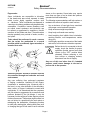
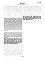
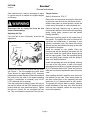
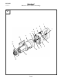
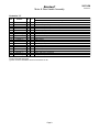
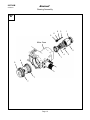
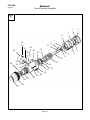
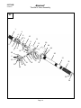
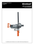
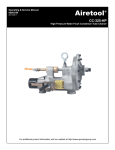
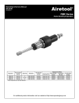
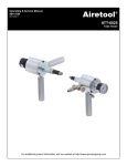
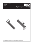
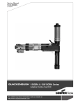
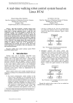
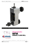
Operating & Service Manual
90074-IM
09/06/2011
Airetool
®
1550-900
Airetrol Rolling Motor
For additional product information visit our website at http://www.apextoolgroup.com
90074-IM
Airetool®
09/06/2011
Description
Tool Specifications
Model: 1550-900 (8404290)
Free Speed
756 rpm
Maximum Torque
30.7 Ft. lbs. (41.6 Nm)
Minimum Torque
4.7 Ft. lbs. (6.4 Nm)
Weight
27 lbs. (12.25 Kg)
Overall Length
18" (457mm)
Side to Center Distance
1-15/16" (50mm)
Recommended Hose Diameter (max. 6' long)
3/4" (13mm)
Air Consumption
70 CFM
Square Drive (Male)
1/2"
Quick Change Chuck (standard)
3/8-1/2"
Quick Change Chuck (optional)
3/4-1"
Tube Capacities *
1-1/2" (38.1mm)
* Note: Varies depending on tube material, gauge, and tube sheet thickness.
Language Version:
Copyright protection:
This Parts Manual is the “Original Instructions”
intended for all persons who will use or repair these
tools.
Apex Tool Group, LLC reserves the right to modify,
supplement or improve this document or the
product without prior notice. This document may
not be reproduced in any way, shape or form, in
full or parts thereof, or copied to another natural
or machine readable language or to a data carrier,
whether electronic, mechanical, optical or otherwise
without the express permission of Apex Tool Group,
LLC.
Product Identification:
Refer to the “Model Nomenclature” page in this
document.
Noise and Vibration:
Refer to documents CE-1015DC and CE-1015TD.
General Description:
Air powered right angle portable nutrunners
equipped with an adjustable clutch.
Intended Use:
These air assembly tools are intended for tightening
of threaded joints or running down fasteners. Use
only for their designated purpose. Do not use as
a hammer, lever or other improper usage that can
cause tool damage and operator injury.
Page 2
Airetool®
90074-IM
Safety Recommendations
Important: For your safety and the safety of
others, read, understand and comply with all
safety recommendations and product operating
instructions.
ALWAYS WEAR PROTECTIVE EQUIPMENT:
Eye and Face Protection:
For additional information on eye and face
protection, refer to Federal OSHA Regulations, 29
Code of Federal Regulations, Section 1910.133,
Eye and Face Protection, and American National
Standards Institute, ANSI A87.1, Occupational
and Educational Eye and Face Protection. Z87.1
is available from the American National Standards
Institute, Inc., 130 Broadway, New York, NY
10018.
Hearing Protection:
09/06/2011
Follow good machine shop
practices. Rotating shafts and
moving components can entangle
and enwrap, and can result in
serious injuries. Never wear long
hair, loose fitting clothes, gloves,
ties or jewelry when working with
or near any power tool with an
exposed rotating shaft or spindle.
When using right angle Airetrols
with lever type throttles, be sure the
throttle is positioned relative to the
angle head so that the throttle will not
become wedged against an adjacent
object in the “ON” position due to
the torque reaction. The angle head
may be repositioned with respect to
the lever to accommodate proper
location for the application. If the tool
is to be reversed, locate the throttle
lever in a neutral position that will
prevent entrapment. Refer to the
operating instructions for additional
information.
Tools with clutches can stall rather
than shut-off if they are adjusted over
the maximum power output of the tool,
or if there is a drop in air pressure.
The operator must then resist the stall
torque until the throttle is released.
Hearing protection is required in high noise areas,
85 dBa or greater. The operation of other tools and
equipment in the area, reflective surfaces, process
noises and resonant structures, can substantially
contribute to and increase the noise level in
the area. For additional information on hearing
protection, refer to Federal OSHA Regulations, 29
Code of Federal Regulations, Section 1910.95,
Occupational Noise Exposure, and American
National Standards Institute, ANSI S12.6 Hearing
Protectors.
Page 3
Higher torque Airetrols, inline and
right angle, are supplied with a torque
reaction bar designed to work with
the torque of the tool it is specified for.
These bars can be braced against the
work or other suitable points to absorb
and relieve the operator of the torque
reaction transmitted by the tool. Tool
balance arms are also available to
absorb the torque reaction of the tool
while balancing the weight of the tool
for improved ergonomic applications.
90074-IM
09/06/2011
Airetool®
Safety Recommendations
Ergonomics:
Some individuals are susceptible to disorders
of the hands and arms when exposed to tasks
which involve highly repetitive motions and/
or vibrations. Those individuals pre-disposed to
vascular or circulatory problems may be particularly
susceptible. Cumulative trauma disorders such
as carpal tunnel syndrome and tendonitis can
be caused or aggravated by repetitious, forceful
exertions of the hands and arms. These disorders
develop gradually over periods of weeks, months,
and years.
Tasks should be performed in such a manner
that the wrists are maintained in a neutral
position which is not flexed, hyper extended, or
turned side to side.
stress on the operator. Some tasks may require
more than one type of tool to obtain the optimum
operator/tool/task relationship.
The following recommendations will help reduce or
moderate the effects of repetitive work motions:
•
Use a minimum of hand grip force consistent
with proper control and safe operation
•
Keep wrists as straight as possible
•
Keep body and hands warm and dry
•
Avoid anything that inhibits blood circulation:
smoking tobacco, cold temperatures, certain
drugs, etc.
•
Avoid highly repetitive movements of the hands
and wrists, and continuous vibration exposure
Before the tool is connected to the air
supply, check the throttle for proper
operation (throttle moves freely and
returns to the “OFF” position when
released). Before removing a tool
from service or changing sockets,
disconnect from the air supply.
Any use of this tool other than it’s intended
purpose could cause damage to the tool or
pose a risk to the operator.
Stressful postures should be avoided and can
be controlled through tool selection and work
environment.
Any user suffering from prolonged symptoms
of tingling, numbness, blanching of the fingers,
clumsiness or weakened grip, nocturnal pain in
the hand, or any other disorder of the shoulders,
arms, wrists, or fingers is advised to consult with
a physician. If it is determined that the symptoms
are job related or aggravated by movements and
postures dictated by the job design, it may be
necessary for the employer to take steps to prevent
further occurrences. These steps might include, but
are not limited to, repositioning the work piece or
redesigning the workstation, reassigning workers
to other jobs, rotating jobs, altering work pace, and/
or changing the type of tool used so as to minimize
Page 4
Airetool®
Operating Instructions
Airetrol model 1550-900 was designed to roll up to
2” O.D. steel tubes. This capacity will vary some
depending upon tube wall thickness and tube sheet
thickness. The Airetrol should be attached to an air
line with a minimum inside diameter of 1/2” and a
maximum length of 25’. If the maximum length is
exceeded, the inside diameter of the hose should
be increased to 3/4” minimum. An inline lubricator
should be installed in the air line and set with the
oil rate adjusted at approximately 6 to 8 drops per
minute.
This product is designed to operate on a minimum
of 90 psig (6.2 bar) and a maximum of 125 psig
(8.6 bar) air pressure. If the tool is properly sized
and applied, higher air pressure is not necessary.
Excessive air pressure increases the load and
stress on tool parts, mandrels, rolls and cages and
may result in premature wear or breakage. The tool
will operate on less air pressure, but the RPM and
the maximum developed torque of the motor will be
proportionally reduced by the loss of pressure. The
tool is equipped with a safety roll throttle, which will
neutralize or shut off the air supply when the handle
is released.
90074-IM
09/06/2011
rolling a joint and checking the inside diameter to
the calculated inside diameter. If the rolled I.D. is
not large enough, the torque should be increased,
and the tube should be rolled again. When the tube
is rolled satisfactorily, we recommend rolling the
second tube for which the finished I.D. has been
calculated, to check the setting. When the required
I.D. is reached and maintained, the entire tube
bundle can be rolled at this setting.
NOTE: THE FIRST TEST TUBES THAT WERE
NOT ROLLED ENOUGH IN THE FIRST TEST
ROLLS SHOULD BE ROLLED AGAIN TO THE
SAME TORQUE SETTING.
As with any power tool, precautions should be
observed during operation.
With the roll throttle held on the right side of the
Airetrol, turn the throttle in the forward or clockwise
direction. The tool will run in the forward direction.
Rotate the grip in the counterclockwise direction
and the tool will reverse to back the expander out
of the tube.
NOTE: ANYTIME THE MOTOR WILL NOT
RUN IN THE FORWARD DIRECTION, ROTATE
THE THROTTLE HANDLE TO THE FULL
COUNTERCLOCKWISE POSITION. THIS WILL
RESET THE TRIP AND ALLOW THE MOTOR TO
RUN IN THE FORWARD DIRECTION.
Select the proper drive chuck that will accept the
Airetool expander being used. The torque adjusting
dial on the front of the machine is divided “0 to 30”.
These particular divisions are for reference only and
to indicate the up and down adjustment, depending
upon the requirement needed to satisfactorily
roll the tube. Elsewhere in this manual is the
recommended method for determining the proper
amount of expansion for tubes. We recommend
starting at a low torque setting of the machine,
Page 5
90074-IM
Airetool®
09/06/2011
Service Instructions
After extensive use, it may be necessary to adjust
or service the tool to maintain the highest degree
of efficiency.
Torque Section:
Refer to Illustrations “B” & “C”
Remove the six cap screws securing the cam case
to the motor case and remove the torque section.
With the cam case in a vertical position, secure the
output end of the spindle in a smooth jawed vise.
Disconnect the air supply line from the tool
before disassembling.
Adjusting the Trip:
If the tool fails to shut off properly, check the trip
adjustment.
Figure 1:
Valve Head
Trip Cover
Screws (2)
Remove the retaining ring from the output end of
the spindle. The spindle can now be removed for
inspection and replacement, if necessary. A new
spindle is necessary only if the faces of the three
splined grooves are brinelled severely by the balls
that operate in the spline.
Install the cleaned or new spindle. Place the
pressure pad with the pressure pins down into the
cam case. Install the needle thrust bearing along
with the spring guide. Place the regulating spring
over the spring guide, making sure the spring is
down over the pilot diameter.
Trip
Screw
Remove the large retaining ring to remove the
cam and ball retainers. Now remove the regulating
spring, spring guide, pressure pad and needle
bearing assembly.
Lock Nut
Remove the two screws to remove the trip cover,
see Figure 1. The trip engages the valve head.
There should be approximately 5/64” clearance
between the outside diameter of the valve head and
the notch of the trip when in the proper operating
position. If adjustment is necessary, use a 5/64”
(.078”) diameter drill as a gauge.
If the trip is adjusted to deeply, loosen the lock nut
and turn the screw until the 5/64” diameter drill just
touches both the valve head and the trip. Tighten
the lock nut. Caution: Do not overtighten the lock
nut. This could break the small end of the trip arm.
Install the operating cam over the spindle, allowing
it to rest on the stop collar. In each of the three
splined grooves install one (1) guide spring and five
(5) 3/16” diameter balls. Note: These are precision
balls and only Airetool replacement parts should be
used.
After installing the balls, install the inner and outer
ball retainers on the cam. Place some grease on
the three incline faces of the operating cam and
install two (2) 1/4” diameter balls on each incline.
The grease will hold the balls in position, allowing
proper installation of the drive cam. After the drive
cam has been installed, replace the snap ring to
secure the assembly.
Page 6
Airetool®
Service Instructions
90074-IM
09/06/2011
Motor Section:
Directional Valve:
Refer to Illustrations “A” & “B”
Refer to Illustration “D”
Remove the ring gear, clean and re-grease the
gears.
To service the directional valve, remove the four (4)
cap screws securing the handle assembly to the
valve body. The valve can now be removed and
inspected for wear or damage.
Remove the four (4) cap screws securing the end
cap to the motor case. Grasp the cylinder liner and
remove the motor assembly from the motor case.
Lightly tap the geared portion of the spindle with a
lead or brass hammer to remove the front bearing
plate from the rotor assembly. Remove the cylinder
to inspect the rotor blades. Under normal usage, new
rotor blades should be installed every six months. If
excessively worn, replace the front bearing support
plate and rear rotor bearing. Adjust the cap screw
so there is approximately .001” to .0015” clearance
between the rotor and the end plate.
Oil all parts and reassemble. Make sure the handle
gasket is in place before installing the handle.
After the motor has been serviced, the torque
section can now be installed on the motor. Adjust
the trip and replace the trip cover.
Clean and re-grease the planetary gear system with
a semi-solid lubricant. Reinstall the motor housing,
aligning the outside groove of the ring gear with the
groove in the motor housing and install the pin.
Install the assembled motor into the motor housing,
placing the dowel pin into the proper hole in the
center of the motor housing. Replace the end cap
and four (4) cap screws.
Having replaced the end cap, which properly aligns
the cylinder and end plate, use an Allen wrench
to evenly tighten the three set screws to the point
of clamping pressure which allows the motor to
operate freely.
Roll Throttle Valve:
Refer to Illustration “D”
To inspect the self closing throttle, remove the pin
and grip. This will expose the self closing spring.
If the spring is broken, replace it making sure one
ear of the spring is hooked on the stop pin. Then,
with pliers, grasp the other ear of the spring and
place on the opposite side of the pin. This places
the spring under torsion so it will return the throttle
valve to the off position when released. Install the
grip and pin.
Page 7
90074-IM
Airetool®
09/06/2011
Motor & Rear Handle Assembly
“A”
1
4
8
5
2
9
11
15
13
17
3
16
12
14
18
Page 8
10
7
6
90074-IM
Airetool®
Motor & Rear Handle Assembly
Illustration "A"
EN
Description
Ref
Number
#
X
1
2
3
4
5
6
7
8
9
10
11
12
13
14
15
16
17
18
3231000
8010023
8010039
8010018
8010014
8565350
8566647 (†)
8010061
8004600
3196200 (†)
8565470
8565450
8565440
8565360
413248 (†)
8565460
8567204 (†)
8565680 (†)
1
4
3
4
4
1
1
1
1
1
1
1
1
1
5
1
1
1
Rear Handle (1000 80)
Socket Head Cap Screw (1/4"-20 x 3/4")
Socket Head Set Screw (1/4"-20 x 1/2")
Socket Head Cap Screw (1/4"-20 x 1-1/2")
Lock Washer (1/4")
End Cap (1550 6)
3 Gasket (1550 63)
1 Button Head Screw (1/4"-28 x 1/2"
1 Washer (1/4")
2 Bearing (625 8)
Spacer (1550 18)
End Plate (1550 16)
Cylinder (1550 15) (includes one 8565690 Spring Pin)
Rotor (1550 7)
15 Rotor Blade (700 13)
End Plate (1550 17)
3 Gasket (1550 17G) - Not Shown
2 Bearing (1550 39)
4
6
4
4
(#) Quantity
(X) Recommended Spare Parts
(†) Parts included in 8405588PT Airetool 1550-900 Service Kit
Page 9
09/06/2011
90074-IM
Airetool®
09/06/2011
Gearing Assembly
“B”
5
6
6
3
1
Motor Case
2
4
1
9
8
7
7
Page 10
3
90074-IM
Airetool®
09/06/2011
Gearing Assembly
Illustration "B"
Ref
Number
#
X
1
2
3
4
5
6
7
8
9
8565670
8565580
8565660 (†)
8565370
8565560
8567541 (†)
8565590
8565570
8565620
2
1
4
1
3
6
2
1
1
4
EN
Description
Bearing (1550 38)
Ring Gear (1550 29)
8 Pin (1550 37)
Gear Cage (1550 8)
6 Planet Gear (1550 27)
12 Bearing (400 16)
4 Bearing (1550 30)
Internal Gear (1550 28)
Spacer (1550 33)
(#) Quantity
(X) Recommended Spare Parts
(†) Parts included in 8405588PT Airetool 1550-900 Service Kit
Page 11
90074-IM
Airetool®
09/06/2011
Cam & Spindle Assembly
“C”
1
4
6
33
11
32
34
30
7
12
29
31
28
14
3
18
10
24
37
36
15
35
17 16
25 23
2
22
21
20
19
26
27
Page 12
13
9
8
5
90074-IM
Airetool®
Cam & Spindle Assembly
Illustration "C"
Ref
Number
#
1
3227500
6
2
3224200
1
3
8565640
1
4
3227600
1
5
3227400
1
6
3227300
1
7
8009800
1
8
3226900
1
9
3232200 (†)
1
10
3222000
1
11
3227200 (†)
15
12
3227100 (†)
3
13
3226700
1
14
3223100
1
15
3223200 (†)
1
16
3223300 (†)
1
17
3223000
1
18
3222900
3
19
8010014
8
20
8010023
6
21
8010059
2
22
3221700
1
23
3222500 (†)
1
24
3222400
1
25
3222300 (†)
1
26
3226300
1
27
8010134 (†)
1
28
3228000
1
29
3226000
1
30
3223700
1
31
3223500
1
32
8010194
2
33
8010193
2
34
8565970
1
35
3223600 (†)
1
36
8010058
1
37
8010079
1
38
8400700
1
39
3236100
1
40
8566705
1
41
8501250
1
42
3235400
1
43
8503500
1
44
8010158
1
Optional Chuck Assemblies
-8400800
1
-8400900
1
-8404820
1
EN
Description
X
18 Steel Ball - 1/4" (1000 51)
2 Retaining Ring (1000 24)
Cam (1550 35)
Retainer (1000 52)
Ball Retainer (1000 50)
Operating Cam (1000 49)
3 Socket Head Set Screw (10-32 x 3/16")
Lock Ring (1000 45)
2 Snap Ring (1000 92)
Spindle (1000 4)
45 Steel Ball - 3/16"
9 Spring (1000 47)
3 Spring (1000 44 400HD)
Spring Guide (1000 12)
2 Bearing (1000 13)
2 Bearing (1000 14)
Pressure Pad (1000 11)
6 Pressure Pin (1000 10)
16 Lock Washer - 1/4"
6 Socket Head Cap Screw (1/4"-20 x 3/4")
2 Socket Head Cap Screw (1/4"-20 x 1")
Cam Case (1000 2)
2 Bearing (1000 7)
2 Retaining Ring (1000 6)
2 Lock Ring (1000 5)
Adjusting Nut (1000 43)
3 Nylon Tip Set Screw (8-32 x 3/16")
Motor Support (1000 56)
1 Dowel Pin (1000 37)
Trip (1000 18)
3 Spring (1000 16)
4 Button Head Cap Screw (6-32 x 1/2")
4 Lock Washer (# 6)
Trip Cover (1550 53)
Follower (1000 17)
2 Socket Head Set Screw (6-32 x 1/2")
2 Hex Nut (6-32)
Quick Change Chuck Assembly (1000 375) - not shown (includes Ref. 39-44)
Chuck Body (1000 375 1) - not shown
Chuck Sleeve (1000 375 2) - not shown
2 Spring (866 375 3) - not shown
2 Chrome Ball - 7/32" - not shown
1 Lock Ring (5108 81)
1 Split Pin (1/8" x 7/8")
Quick Change Chuck Assembly (1000 500)
3/4" Chuck Assembly (1000 750)
1" Chuck Assembly (1000 1000)
(#) Quantity
(X) Recommended Spare Parts
(†) Parts included in 8405588PT Airetool 1550-900 Service Kit
Page 13
09/06/2011
90074-IM
Airetool®
09/06/2011
Throttle & Valve Assembly
“D”
1
5
4
6
10
9
12
11
2
13
26
28
3
7
20
29
8
14
16
30
5
17
22
25
23
24
19
18
31
15
32
27
21
35
36
Page 14
90074-IM
Airetool®
Throttle & Valve Assembly
Illustration "D"
Ref
Number
#
EN
Description
X
1
8566060
1
Throttle Grip (1000 39)
2
8566643 (†)
1
3 Pin (1000 39P)
3
8566061 (†)
1
3 Centering Spring (1000 38)
4
8010135
2
4 Split Pin (1/8" x 3/4")
5
8010038
8
8 Socket Head Cap Screw (10-32 x 1/2")
6
3231300 (†)
1
2 Pin (1000 83)
7
3225400
1
Retainer (1000 33S)
8
3231100 (†)
1
2 Bearing (1000 81)
9
8566059
1
Valve Actuator (1000 30R)
10
3231500 (†)
1
3 Gasket (1000 85)
11
8405290
1
Valve Assembly (1000 27S 34S)
12
8565390
1
Valve Body (1550 10)
13
8566645 (†)
1
3 Gasket (1550 61)
14
8010064
4
4 Socket Head Cap Screw (1/4"-20 x 2-1/2")
15
3225800
1
Valve Bushing (1000 35S)
16
3231200
1
Bushing (1000 82)
17
3167600 (†)
1
3 O-Ring (500 31)
18
8565520
1
Valve (150 23)
19
8011036 (†)
1
3 Valve Washer (1550 W)
20
8566646 (†)
1
3 Gasket (1550 62)
21
8565490
1
Valve Box (1550 20)
22
3128500
2
4 Pin (400 18)
23
8008000
1
1 Socket Head Cap Screw (8-32 x 3/8")
24
8565530
1
Valve Head (1550 24)
25
3224000
1
Bushing (1000 22)
26
8565310
1
Case (1550 2)
27
8565330
1
Handle Base (1550 4)
28
8010014
4
4 Lock Washer - 1/4"
29
8010023
4
4 Socket Head Cap Screw (1/4"-20 x 3/4")
30
3211400
1
Exhaust Extension (750 17 12)
31
3211700
1
Coupling (750 17 C)
32
6400800
1
1 Muffler Assembly (A 1000 61 MF) (includes Ref. 33-36)
33
3228750
1
Grip (1000 61 AB) - not shown
34
3229250
1
1 Baffle Assembly (1000 61 G) - not shown
35
3232500 (†)
1
Deflector (1000 95)
36
3232600 (†)
1
1 Snap Ring (1000 96)
37
4105094
1
Hose Assembly (1/2 2 Ply x 10) - not shown
Wrenches Included with Tool (not shown)
-8010144
1
Hex Wrench - 1/16"
-8010145
1
Hex Wrench - 5/64"
-8010149
1
Hex Wrench - 5/32"
-8010150
1
Hex Wrench - 3/16"
-8010148
1
Hex Wrench - 9/64"
-8010308
1
Hex Wrench - 3/32"
-8010147
1
Hex Wrench - 1/8"
(#) Quantity
(X) Recommended Spare Parts
(†) Parts included in 8405588PT Airetool 1550-900 Service Kit
Page 15
09/06/2011
Sales & Service Centers
Note: All locations may not service all products. Please contact the nearest Sales & Service Center for
the appropriate facility to handle your service requirements.
Dallas, TX
Detroit, MI
Apex Tool Group
Apex Tool Group
Sales & Service Center
Sales & Service Center
1470 Post & Paddock
2630 Superior Court
Grand Prairie, TX 75050
Auburn Hills, MI 48326
Tel: 972-641-9563
Tel: 248-391-3700
Fax: 972-641-9674
Fax: 248-391-7824
Houston, TX
Apex Tool Group
Sales & Service Center
6550 West Sam Houston
Parkway North, Suite 200
Houston, TX 77041
Tel: 713-849-2364
Fax: 713-849-2047
Los Angeles, CA
Seattle, WA
York, PA
Apex Tool Group
Apex Tool Group
Apex Tool Group
Sales & Service Center
Sales & Service Center
Sales & Service Center
15503 Blackburn Avenue
2865 152nd Avenue N.E.
3990 East Market Street
Norwalk, CA 90650
Redmond, WA 98052
York, PA 17402
Tel: 562-623-4457
Tel: 425-497-0476
Tel: 717-755-2933
Fax: 562-802-1718
Fax: 425-497-0496
Fax: 717-757-5063
Germany
England
France
Apex Tool Group
Apex Tool Group
Apex Tool Group SAS
GmbH & Co. OHG
GmbH & Co. OHG
25 rue Maurice Chevalier
Industriestraße 1
C/O Spline Gauges
77330 Ozoir-La-Ferrière
73463 Westhausen
Piccadilly, Tamworth
France
Germany
Staffordshire B78 2ER
Tel: +33 1 6443 2200
Tel: +49 (0) 73 63 81 0
United Kingdom
Fax: +33 1 6443 1717
Fax: +49 (0) 73 63 81 222
Tel: +44 1827 8741 28
Fax: +44 1827 8741 28
Mexico
Cooper Tools
de México S.A. de C.V.
a company of
Apex Tool Group, LLC
Vialidad El Pueblito #103
Parque Industrial Querétaro
Querétaro, QRO 76220
Mexico
Tel: +52 (442) 211-3800
Fax: +52 (442) 103-0443
Brazil
Cooper Tools Industrial Ltda.
a company of
Apex Tool Group, LLC
Av. Liberdade, 4055
Zona Industrial - Iporanga
18087-170 Sorocaba
SP Brazil
Tel: +55 15 2383929
Fax: +55 15 2383260
Apex Tool Group, LLC
1000 Lufkin Road
Apex, NC 27539
Phone: 919-387-0099
Fax:
919-387-2614
www.apextoolgroup.com
90074-IM/Printed in USA 09/2011/Copyright © Apex Tool Group, LLC
Lexington, SC
Apex Tool Group
670 Industrial Drive
Lexington, SC 29072
Tel: 800-845-5629
Tel: 803-951-7544
Fax: 803-358-7681
Canada
Apex Tool Group
Sales & Service Center
5925 McLaughlin Road
Mississauga, Ont. L5R 1B8
Canada
Tel: 905-501-4785
Fax: 905-501-4786
China
Cooper (China) Co., Ltd.
a company of
Apex Tool Group, LLC
955 Sheng Li Road,
Heqing Pudong, Shanghai
China 201201
Tel: +86-21-28994176
Fax: +86-21-51118446
Hungary
Cooper Tools Hungaria Kft.
a company of
Apex Tool Group, LLC
Berkenyefa sor 7
Pf: 640
9027 Györ
Hungary
Tel: +36 96 66 1383
Fax: +36 96 66 1135
Airetool
®