1
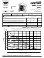
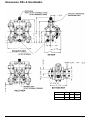
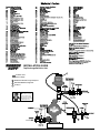
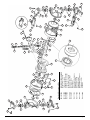
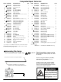
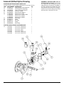
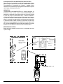
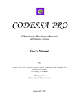
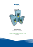
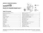
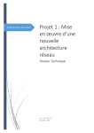
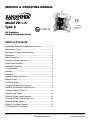
SERVICE & OPERATING MANUAL
Model PB¼-A
Type 3
CE
II 2GD T5
U.S. Patent #
5,996,627 and
6,241,487
Air-Operated
Double Diaphragm Pump
Table of Contents
Engineering Data and Temperature Limitations.....................1
Performance Curve................................................................1
Explanation of Pump Nomenclature ......................................2
Dimensions ............................................................................3
Metric Dimensions .................................................................4
Principle of Pump Operation..................................................5
Check Valve Servicing ...........................................................5
Diaphragm Servicing .............................................................5
Troubleshooting .....................................................................6
Warranty ................................................................................6
Recycling ...............................................................................6
Important Safety Information .................................................6
Material Codes ......................................................................7
Installation Guide ...................................................................7
Composite Repair Parts Drawing ..........................................8
Available Service and Conversion Kits ..................................8
Composite Repair Parts List ..................................................9
Grounding the Pump .............................................................9
Solenoid Shifted Option Drawing .........................................10
Solenoid Shifted Air Valve Parts List ...................................10
Solenoid Shifted Options .....................................................11
Solenoid Connector Drawing ...............................................11
CE Declaration of Conformity ..............................................12
WARREN RUPP, INC. • A Unit of IDEX Corporation • P.O. Box 1568, Mansfield, Ohio 44901-1568 USA • Telephone (419) 524-8388 • Fax (419) 522-7867
www.warrenrupp.com
pb025nmdl3sm-REV1008
Model PB¼-A
Quality System
ISO9001 Certified
Type 3
II 2GD T5
Environmental
Management System
ISO14001 Certified
Air-Operated
Double Diaphragm Pump
CE
U.S. Patent #
5,996,627 and
6,241,487
Engineering, Performance
& Construction Data
CAPACITY
INTAKE/DISCHARGE PIPE SIZE
AIR VALVE
0 to 4 gallons per minute
(0 to 15 liters per minute)
¼" (6mm) NPT (internal)
½" (13mm) NPT (external)
SOLIDS-HANDLING
No-lube, no-stall
design
Up to 1/32" (1mm)
HEADS UP TO
CAUTION! Operating temperature limitations are as follows:
Materials
275°F
-35°F
104°C
0°F
-18°C
32°F
0°C
-20°F
-29°C
121°C
180°F
82°C
Conductive Acetal
190°F
II 2GD T5
50° to 212°F
10° to 100°C
-37°C
250°F
Polypropylene
50° to 212°F
10° to 100°C
-40°C
220°F
PVDF
Optimum**
-40°F
135°C
Virgin PTFE Chemically inert, virtually impervious. Very few chemicals are known to react chemically
with PTFE: molten alkali metals, turbulent liquid or gaseous fluorine and a few fluoro-chemicals such
as chlorine trifluoride or oxygen difluoride which readily liberate free fluorine at elevated temperatures.
.01 US Gallons / .04 liters
Operating Temperatures
Minimum*
Maximum*
Santoprene® Injection molded thermoplastic elastomer with no fabric layer. Long mechanical flex life.
Excellent abrasion resistance.
DISPLACEMENT/STROKE
100 psi or 231 ft. of water
(7 bar or 70 meters)
88°C
7
PSI
BAR
MODEL PB¼-A Performance Curve
Performance based on the following: elastomer fitted pump, flooded suction, water at ambient conditions.
The use of other materials and varying hydraulic conditions may result in deviations in excess of 5%.
AIR CONSUMPTION SCFM (M3/hr)
1(1.7)
100
2(3.4)
10
0P
90
SI
6
(6
.8
80
80
5
3(5.1)
Ba
r)
4(6.8)
PS
I (5
70
.44
5(8.5)
Ba
HEAD
r)
4
60
60
6(10.2)
PS
I (4
50
.08
Bar
)
3
40
40 P
2
SI (2
30
.72
Bar)
20
1
20 PS
I (1.3
10
0
6 Bar
) Air
Inlet
Press
ure
0
0
.5
1.0
2.0
1.5
2.5
3.0
3.5
4.0
4.5
U.S. Gallons per minute
0
2
4
6
8
10
12
14
16
Liters per minute
(SANDPIPER® pumps
pb025nmdl3sm-REV1008
are designed to be powered only by compressed air)
Page 1
Explanation of Pump Nomenclature
PB¼-A
Manifold
Outer
Inner
Intermediate Diaphragm
Outer
Diaphragm Diaphragm
Housing
Chamber
Rod
Plate
Plate
Hardware
Valve
Seat
Diaphragm
Ball Valve Air
Material Valve
Cap
Options
Shipping
Weight
(lbs.)
TS-3-PP
PP
PP
PP
2011-AL
PP*
416SS
301/302SS
PP
S
S
PP*
PP*
-
4
TU-3-PP
PP
PP
PP
2011-AL
PP*
416SS
301/302SS
PP
S
T
PP*
PP*
-
4
TT-3-PP
PP
PP
PP
2011-AL
PP*
416SS
301/302SS
PP
T
T
PP*
PP*
-
4
TS-3-K
K
K
K
2011-AL
PP*
416SS
301/302SS
K
S
S
PP*
PP*
-
5
TU-3-K
K
K
K
2011-AL
PP*
416SS
301/302SS
K
S
T
PP*
PP*
-
5
TT-3-K
K
K
K
2011-AL
PP*
416SS
301/302SS
K
T
T
PP*
PP*
-
5
TS-3-CA
CA
CA
CA
2011-AL
CA*
416SS
301/302SS
AC
S
S
CA*
CA*
-
4
TU-3-CA
CA
CA
CA
2011-AL
CA*
416SS
301/302SS
AC
S
T
CA*
CA*
-
4
TT-3-CA
CA
CA
CA
2011-AL
CA*
416SS
301/302SS
AC
T
T
CA*
CA*
-
4
TS-3-PPE0
PP
PP
PP
2011-AL
PP*
416SS
301/302SS
PP
S
S
E
PP*
E0
4
TS-3-PPE1
PP
PP
PP
2011-AL
PP*
416SS
301/302SS
PP
S
S
E
PP*
E1
4
TS-3-PPE2
PP
PP
PP
2011-AL
PP*
416SS
301/302SS
PP
S
S
E
PP*
E2
4
TS-3-PPE3
PP
PP
PP
2011-AL
PP*
416SS
301/302SS
PP
S
S
E
PP*
E3
4
TS-3-PPE4
PP
PP
PP
2011-AL
PP*
416SS
301/302SS
PP
S
S
E
PP*
E4
4
TS-3-PPE5
PP
PP
PP
2011-AL
PP*
416SS
301/302SS
PP
S
S
E
PP*
E5
4
TS-3-PPE6
PP
PP
PP
2011-AL
PP*
416SS
301/302SS
PP
S
S
E
PP*
E6
4
TS-3-PPE7
PP
PP
PP
2011-AL
PP*
416SS
301/302SS
PP
S
S
E
PP*
E7
4
TS-3-PPE8
PP
PP
PP
2011-AL
PP*
416SS
301/302SS
PP
S
S
E
PP*
E8
4
TS-3-PPE9
PP
PP
PP
2011-AL
PP*
416SS
301/302SS
PP
S
S
E
PP*
E9
4
TS-3-PPP0
PP
PP
PP
2011-AL
PP*
416SS
301/302SS
PP
S
S
PP
PP*
P0
4
TS-3-PPP2
PP
PP
PP
2011-AL
PP*
416SS
301/302SS
PP
S
S
PP
PP*
P2
4
Horizontal suction and vertical discharge are standard. All combinations of suction and discharge are available.
Meanings of Abbreviations:
AC = Acetal
AL = Aluminum
CA = Conductive Acetal**
K = PVDF
PP = Polypropylene
SS = Stainless Steel
T = PTFE
S = Santoprene
Kit Options
00.= None
P0.= 10-30VDC Pulse Output Kit
P2.= 110/120 or 220/240VAC
Pulse Output Kit
E0.= Solenoid Kit w/24VDC Coil
E1.= Solenoid Kit w/24VDC
Explosion-Proof Coil
E2.= Solenoid Kit w/24VAC/12VDC Coil
E3.= Solenoid Kit w/12VDC Coil
Explosion-Proof
E4.= Solenoid Kit w/110VAC Coil
E5.= Solenoid Kit w/110VAC
Explosion-Proof Coil
E6.= Solenoid Kit w/220VAC Coil
E7.= Solenoid Kit w/220VAC
Explosion-Proof Coil
E8.= Solenoid Kit with 110VAC, 50 Hz
Explosion-Proof Coil
E9.= Solenoid Kit with 230VAC, 50 Hz
Explosion-Proof Coil
SP.= Stroke Indicator Pins
ATEX Compliant ONLY with no options.
* Designates Glass Filled
** Note: Only Conductive Acetal equipped pumps with no options are ATEX compliant
pb025nmdl3sm-REV1008
Page 2
Dimensions: PB¼-A Non-Metallic
pb025nmdl3sm-REV1008
Dimension
A
B
C
Standard
7"
3 1/8"
5 1/2"
Pulse Output Kit
7"
3 1/8"
5 1/2"
Page 3
Metric Dimensions: PB¼-A Non-Metallic
Dimension
pb025nmdl3sm-REV1008
A
B
C
Standard
178
79
140
Pulse Output Kit
178
79
140
Page 4
PRINCIPLE OF PUMP OPERATION
This ball type check valve pump is
powered by compressed air and is a
1:1 ratio design. The inner side of one
diaphragm chamber is alter nately
pressur ized while simultaneously
exhausting the other inner chamber.
This causes the diaphragms, which are
connected by a common rod secured by
plates to the centres of the diaphragms,
to move in a reciprocating action. (As
one diaphragm performs the discharge
stroke the other diaphragm is pulled
to perform the suction stroke in the
opposite chamber.) Air pressure is
applied over the entire inner surface
of the diaphragm while liquid is discharged from the opposite side of the
diaphragm. The diaphragm operates in a
balanced condition during the discharge
stroke which allows the pump to be
operated at discharge heads over 200 feet
(61 meters) of water.
For maximum diaphragm life, keep the
pump as close to the liquid being pumped
as possible. Positive suction head in
excess of 10 feet of liquid (3.048 meters)
may require a back pressure regulating
device to maximize diaphragm life.
Alternate pressurizing and exhausting
of the diaphragm chamber is performed
by an externally mounted, pilot operated,
four way spool type air distribution valve.
When the spool shifts to one end of the
valve body, inlet pressure is applied to
one diaphragm chamber and the other
diaphragm chamber exhausts. When the
spool shifts to the opposite end of the
valve body, the pressure to the chambers
is reversed. The air distribution valve
spool is moved by a internal pilot valve
which alternately pressurizes one end
of the air distribution valve spool while
exhausting the other end. The pilot
valve is shifted at each end of the diaCHECK VALVE SERVICING
Need for inspection or service is
usually indicated by poor priming,
unstable cycling, reduced performance or
the pump's cycling but not pumping.
Remove the sixteen machine screws
securing the manifold assemblies to the
outer chambers. Inspect the surfaces
of both check valve and seat for wear
or damage that could prevent proper
sealing. If pump is to prime properly,
valves must seat air tight.
DIAPHRAGM SERVICING
Remove the two V-Band clamps
securing the outer chambers to the
inter mediate housing. Remove the
diaphragm assembly (outer plate,
diaphragm, inner plate) by turning the
assembly counterclockwise using a 1/2"
(1.27 cm) wrench on the outer plate
lugs. (If a socket is used, it must be a six
point socket.) The interior components
consisting of the shaft seal and pilot
valve assembly are now accessible for
service.
Procedures for reassembling the
diaphragms are the reverse of the above.
Install the diaphragm with the natural
bulge outward.
Install the outer diaphragm plate on
the outside of the diaphragm and make
certain that the large radius side of the
inner plate is toward the diaphragm.
Tighten the outer diaphragm plate to
approximately 30 in./lbs. (3.39 Newton
meters).
Torque while allowing the diaphragm
to turn freely with plates. Use a wrench
on the outer diaphragm plate of the
pb025nmdl3sm-REV1008
phragm stroke when a actuator plunger is
contacted by the diaphragm plate. This
actuator plunger then pushes the end
of the pilot valve spool into position to
activate the air distribution valve.
The chambers are connected
with manifolds with a suction and
discharge check valve for each chamber,
maintaining flow in one direction through
the pump.
INSTALLATION AND START-UP
Locate the pump as close to the
product being pumped as possible. Keep
the suction line length and number of
fittings to a minimum. Do not reduce the
suction line diameter.
For installations of rigid piping, short
sections of flexible hose should be
installed between the pump and the
piping. The flexible hose reduces
vibration and strain to the pumping
system. A surge suppressor is
recommended to fur ther reduce
pulsation in flow.
AIR SUPPLY
Air supply pressure cannot exceed
100 psi (7 bar). Connect the pump
air inlet to an air supply of sufficient
capacity and pressure required for
desired performance. When the air
supply line is solid piping, use a short
length of flexible hose not less than 1/2"
(13mm) in diameter between the pump
and the piping to reduce strain to the
piping. The weight of the air supply line,
regulators and filters must be supported
by some means other than the air inlet
cap. Failure to provide support for the
piping may result in damage to the pump.
A pressure regulating valve should be
installed to insure air supply pressure does
not exceed recommended limits.
opposite side to keep rod from rotating. If
the opposite chamber is assembled, the
rod need not be held.
EXTERNALLY SERVICEABLE MAIN AIR
DISTRIBUTION VALVE
To service the main air distribution,
first shut-off and disconnect the air supply
to the pump. Remove the four long hex cap
screws and hex nuts (on opposite side of
pump) which fasten the main air valve
body (item 1), gaskets (item 8 and 11),
muffler (item 14), and caps (item 6 and
15) to the pump.
Once the main air valve body is off the
pump remove the retaining rings (items 7)
that hold the end caps in place. Remove
the end caps (items 6) to inspect the spool
and sleeve. Remove the main air spool
(part of item 2) and inspect for damage or
wear. Inspect the inside diameter of the
main air valve (item 2) for dirt, scratches,
or other contaminants. Remove and
replace the sleeve if needed. When
reinstalling the sleeve, apply a light
coating of grease to the six o-rings
(item 3) before inserting the sleeve into
the main air valve body. Align the holes
in the sleeve with the slots in main
valve body, making sure the sleeve is
centered in the bore. Clean the main
air valve spool, lightly grease the orings, and insert into the sleeve flush
to one end. Reinstall the end caps and
retaining rings. The main air valve body is
now ready to put back on the pump.
Assemble the air inlet cap (item 9),
valve body gasket (item 8), to the main air
valve body (making sure the five rectangular slots face the air inlet cap), and the
intermediate gasket onto the four hex cap-
AIR VALVE LUBRICATION
BETWEEN USES
The air distribution valve and the
pilot valve are designed to operate
WITHOUT lubrication. This is the preferred mode of operation. There may be
instances of personal preference or poor
quality air supplies when lubrication of
the compressed air supply is required.
The pump air system will operate with
properly lubricated compressed air supply.
Proper lubrication requires the use of an
air line lubricator (available from Warren
Rupp) set to deliver one drop of SAE
10 non-detergent oil for every 20 SCFM
(9.4 liters/sec.) of air the pump consumes
at the point of operation. Consult the
pump’s published Performance Curve to
determine this.
When the pump is used for materials
that tend to settle out or solidify when not
in motion, the pump should be flushed
after each use to prevent damage.
(Product remaining in the pump between uses could dry out or settle out.
This could cause problems with the
diaphragms and check valves at restart.)
In freezing temperatures the pump must
be completely drained between uses in
all cases.
AIR LINE MOISTURE
Water in the compressed air supply
can create problems such as icing or
freezing of the exhaust air, causing the
pump to cycle erratically or stop operating.
Water in the air supply can be reduced
by using a point-of-use air dryer to
supplement the user’s air dr ying
equipment. This device removes water
from the compressed air supply and
alleviates the icing or freezing problems.
Figure 1
AIR INLET AND PRIMING
To start the pump, open the air valve
approximately ½ to ¾ turn. After the pump
primes, the air valve can be opened to
increase air flow as desired. If opening
the valve increases cycling rate, but does
not increase the rate of flow, cavitation
has occurred. The valve should be closed
slightly to obtain the most efficient air flow
to pump flow ratio.
Figure 2
screws and install onto the pump. Slide the
muffler (item 14) and the exhaust cap (item
15) over the capscrews. Re-install the
washers (item 10) and hex nuts (items 16)
onto the four hex capscrews and torque to
30 in/lbs. (3.39 Newton meters).
SERVICING THE PILOT VALVE
To remove the pilot valve spool (item
23) first remove the end o-ring (item 24)
from one end of spool. Slide the spool
out of the sleeve and inspect the five
remaining o-rings (items 24) for damage
or wear. If necessary, replace damaged
o-rings. Inspect the inner diameter of pilot
valve sleeve (item 20) for scratches, dirt,
or other contaminants. Replace the sleeve
if necessary. To remove the sleeve first
remove the retaining ring from one end.
When installing a pilot valve sleeve first
lightly grease the six o-rings (items 21).
Insert the sleeve into the chamfered end
of bore on the intermediate bracket (item
13). Push the sleeve in until the shoulder
is flush to intermediate bracket surface
and install the retaining ring (item 22).
To install the pilot valve spool first lightly
grease the four interior o-rings and insert
into the pilot valve sleeve. After inserting the spool into the sleeve install the
remaining loose o-rings onto spool.
S E RV I C I N G D I A P H R AG M RO D
SEALS
To service the rod seals (item 18)
first remove pilot valve, then remove
the inserts on each of the intermediate
brackets (item 17) by pr ying them
out with a small flat screwdriver. After
removing the inserts take the K-R rod
seals out of the inserts and replace.
When reinstalling the seals, make sure
the open side of the seals face into the
counterbore in the inserts. To install the
inserts into intermediate bracket, simply
press the insert into the counterbore in
each of the intermediate bracket, making
sure that the closed side of insert faces out.
The inserts should be flush to the surface
of the intermediate bracket or slightly
below the surface when fully installed.
Figure 3
Figure 4
Page 5
TROUBLESHOOTING
Possible Symptoms:
• Pump will not cycle.
• Pump cycles, but produces no
flow.
• Pump cycles, but flow rate is
unsatisfactory.
• Pump cycle seems unbalanced.
• Pump cycle seems to produce
excessive vibration.
What to Check: Excessive suction lift
in system.
Corrective Action: For lifts
exceeding 20 feet (6 meters), filling the
pumping chambers with liquid will prime
the pump in most cases.
What to Check: Excessive flooded
suction in system.
Corrective Action: For flooded
c o n d i t i o n s ex c e e d i n g 1 0 fe e t
(3 meters) of liquid, install a back
pressure device.
What to Check: System head exceeds
air supply pressure.
Corrective Action: Increase the
inlet air pressure to the pump. Most
diaphragm pumps are designed for 1:1
pressure ratio at zero flow.
What to Check: Air supply pressure or
volume exceeds system head.
Corrective Action: Decrease inlet air pressure and volume to the
pump as calculated on the published
PERFORMANCE CURVE. Pump is
cavitating the fluid by fast cycling.
What to Check: Undersized suction
line.
Corrective Action: Meet or exceed
pump connection recommendations shown on the DIMENSIONAL
DRAWING.
W h a t t o C h e ck : R e s t r i c t e d o r
undersized air line.
Corrective Action: Install a larger
air line and connection. Refer to air
inlet recommendations shown in your
pump’s SERVICE MANUAL.
What to Check: Check ESADS, the
Externally Serviceable Air Distribution
System of the pump.
Corrective Action: Disassemble and
inspect the main air distribution valve,
pilot valve and pilot valve actuators.
Refer to the parts drawing and air valve
section of the SERVICE MANUAL.
Check for clogged discharge or closed
valve before reassembly.
What to Check: Rigid pipe
connections to pump.
Corrective Action: Install flexible
connectors and a Warren Rupp ®
Tranquilizer® surge suppressor.
What to Check: Blocked air exhaust
muffler.
Corrective Action: Remove muffler
screen, clean or de-ice and reinstall.
Refer to the Air Exhaust section of your
pump SERVICE MANUAL.
IMPORTANT
Read these safety warnings
and instructions in this
manual completely, before
installation and start-up
of the pump. It is the
responsibility of the purchaser to retain this
manual for reference. Failure to comply with
the recommendations stated in this manual will
damage the pump, and void factory warranty.
What to Check: Pumped fluid in air
exhaust muffler.
Corrective Action: Disassemble pump chambers. Inspect for
diaphragm rupture or loose diaphragm plate assembly. Refer to the
Diaphragm Replacement section of
your pump SERVICE MANUAL.
What to Check: Suction side air
leakage or air in product.
Corrective Action: Visually inspect
all suction side gaskets and pipe
connections.
What to Check: Obstructed check
valve.
Corrective Action: Disassemble
t h e we t e n d o f t h e p u m p a n d
manually dislodge obstruction in
the check valve pocket. Refer to
the Check Valve section of the pump
SERVICE MANUAL for disassembly
instructions.
What to Check: Worn or misaligned
check valve or check valve seat.
Corrective Action: Inspect check
valves and seats for wear and proper
seating. Replace if necessary. Refer
to Check Valve section of the pump
SERVICE MANUAL for disassembly
instructions.
What to Check: Blocked suction line.
Corrective Action: Remove or flush
obstruction. Check and clear all
suction screens and strainers.
Before pump operation,
inspect all gasketed
fasteners for looseness
caused by gasket creep. Retorque loose fasteners to
prevent leakage. Follow recommended torques
stated in this manual.
Take action to prevent static
sparking. Fire or explosion
can result, especially when
handling flammable liquids.
The pump, piping, valves,
containers or other miscellaneous equipment
must be grounded.
This pump is pressurized
internally with air pressure
during operation. Always
make certain that all bolting
is in good condition and
that all of the correct bolting
is reinstalled during assembly.
WARNING
WARNING
Before maintenance
or repair, shut off the
compressed air line,
bleed the pressure, and
disconnect the air line from
the pump. The discharge line may be pressurized
and must be bled of its pressure.
WARNING
Airborne particles and loud
noise hazards.
Wear ear and eye
protection.
pb025nmdl3sm-REV1008
What to Check: Blocked pumping
chamber.
Corrective Action: Disassemble
and inspect the wetted chambers
of the pump. Remove or flush any
obstructions.
What to Check: Entrained air or
vapor lock in one or both pumping
chambers.
Corrective Action: Purge chambers
through tapped chamber vent plugs.
PURGING THE CHAMBERS OF
AIR CAN BE DANGEROUS! Contact
the Warren Rupp Technical Services
Department before performing this
procedure. Any model with top-ported
discharge will reduce or eliminate
problems with entrained air.
If your pump continues to perform
below your expectations, contact
your local Warren Rupp Distributor
o r fa c t o r y Te c h n i c a l S e r v i c e s
Group for a ser vice evaluation.
WARRANTY
This pump is warranted for a period of
five years against defective material
and workmanship. Failure to comply
with the recommendations stated in this
manual voids all factory warranty.
WARNING
WARNING
WARNING
CAUTION
What to Check: Blocked discharge
line.
C o r r e c t i v e A c t i o n : C h e ck fo r
obstruction or closed discharge line
valves.
When used for toxic or
aggressive fluids, the pump
should always be flushed
clean prior to disassembly.
WARNING
In the event of diaphragm
rupture, pumped material
may enter the air end of the
pump, and be discharged
into the atmosphere. If
pumping a product which is hazardous or toxic,
the air exhaust must be piped to an appropriate
area for safe disposition.
Before doing any
maintenance on the pump,
be certain all pressure is
completely vented from the
pump, suction, discharge,
piping, and all other openings and connections.
Be certain the air supply is locked out or made
non-operational, so that it cannot be started
while work is being done on the pump. Be certain
that approved eye protection and protective
clothing are worn all times in the vicinity of the
pump. Failure to follow these recommendations
may result in serious injury or death.
II 2GD T5
CE
Pump complies with EN809 Pumping Directive, Directive 98/37/EC Safety of Machinery,
and Directive 94/9/EC, EN13463-1 Equipment
for use in Potentially Explosive Environments.
For reference to the directive certificates visit: www.warrenrupp.com. The Technical File
No. AX1 is stored a KEMA, Notified Body 0344,
under Document #203040000.
RECYCLING
Many components of Warren Rupp
Metallic AODD pumps are made of
recyclable materials (see chart on
page 9 for material specifications). We
encourage pump user to recycle worn
out parts and pumps whenever possible,
after any hazardous pumped fluids are
thoroughly flushed.
Page 6
INSTALLATION GUIDE
Top Discharge Ball Valve Unit
1
Available from
Warren Rupp
1 DA05 Non-Metallic Surge Dampener
Surge
Dampener
Limited to
100 psi
2 020-049-000 Filter/Regulator
3 Air Dryer
CAUTION
The air exhaust should be
piped to an area for safe
disposition of the product
being pumped, in the event
of a diaphragm failure.
3
2
pb025nmdl3sm-REV1008
Page 7
pb025nmdl3sm-REV1008
Page 8
37
37
33
33
35
27
31
26
16
28
43
10
30
476-129-000
476-117-644
476-117-600
476-117-354
475-149-520
475-149-552
031-101-000
475-145-000
475-154-000
031-107-551
031-107-503
15
25
29
18
14
17
Main Air Valve Body Assembly
Main Air Valve Body Assembly
(Conductive Acetal only)
Pilot Valve Assembly
Air Exhaust Conversion Kit
Air Exhaust Conversion Kit
(Conductive Acetal only)
Pail Transfer Kit in PVDF
Pail Transfer Kit in
Polypropylene
Wetted End Kit Santoprene
Diaphragms & Balls
Wetted End Kit PTFE
Diaphragms & Balls
Wetted End Kit Santoprene
Diaphragms & Balls
Air End Kit
Service & Accessory Kits
32
34
32
34
39
13
18
22
20
21
12
3
6
19
6
18
3
7
24
1
8
10
25
17
17
7
3
2
28
9
11
38
30
40
43
29
40
26
38
41
40
41
27
42
32
31
32
37
40
39
33
34
37
35
38
33
34
37
Composite Repair Parts List
ITEM PART NO.
1
2
3
6
7
8
9
10
11
12
13
14
15
16
17
18
19
20
21
22
23
24
25
26
095-077-551
095-077-503
031-106-000
560-101-360
165-074-551
165-074-503
675-051-115
360-085-360
360-085-379
165-072-551
165-072-503
901-037-115
170-103-115
360-084-360
360-084-379
114-019-551
114-019-503
530-022-550
165-073-551
165-073-503
545-003-115
449-021-551
449-021-503
720-031-359
685-046-120
755-038-000
560-066-360
675-047-115
775-038-000
560-029-374
612-147-150
286-069-354
DESCRIPTION
Body, Main Air Valve
Body, Main Air Valve
Sleeve & Spool Set
O-Rings
Cap, End with O-Ring
Cap, End with O-Ring
Ring, Retaining
Gasket, Valve Body
Gasket, Valve Body (Conductive Acetal Only)
Cap, Air Inlet
Cap, Air Inlet
Washer, Flat 1/4"
Capscrew, Hex Head 1/4-20 5" Long
Gasket, Intermediate Bracket
Gasket, Intermediate Bracket
(Conductive Acetal Only)
Intermediate, Bracket
Intermediate, Bracket
Muffler
Cap, Air Exhaust
Cap, Air Exhaust
Nut, Hex 1/4-20UNC
Insert, Gland
Insert, Gland
Seal, K-R
Rod, Diaphragm
Sleeve, Pilot Valve with O-rings
O-rings
Ring, Retaining - Pilot Valve Sleeve
Spool, Pilot Valve with O-rings
O-rings
Plate, Inner Diaphragm
Diaphragm
QTY
1
1
1
8
2
2
2
1
1
1
1
8
4
1
1
1
1
1
1
1
4
2
2
2
1
1
6
1
1
6
2
2
ITEM
27
28
29
30
31
32
33
34
35
37
38
39
40
41
42
43
54
PART NO.
DESCRIPTION
286-070-600
612-146-520
612-146-502
612-146-552
200-057-115
100-002-115
545-027-337
196-145-520
196-145-502
196-145-552
720-032-600
722-073-520
722-073-506
722-073-552
050-033-354
050-034-600
312-095-520
312-095-502
312-095-552
706-023-115
544-004-115
312-096-520
312-096-502
312-096-552
720-033-600
518-127-520
518-127-502
518-127-552
518-128-520
518-128-502
518-128-552
360-086-360
920-025-000
Diaphragm
2
Plate, Outer Diaphragm
2
Plate, Outer Diaphragm
2|
Plate, Outer Diaphragm
2
Clamp, V-Band
2
T-Bolt
2
Nut, Hex 1/4-28UNF
2
Chamber, Outer
2
Chamber, Outer
2
Chamber, Outer
2
Seal, Check Valve
8
Seat, Check Valve
4
Seat, Check Valve
4
Seat, Check Valve
4
Ball, Check
4
Ball, Check
4
Elbow, Suction
2
Elbow, Suction
2
Elbow, Suction
2
Screw, Machine 10-32UNF x 1" Long
32
Nut, Hex Flange 10-32UNF
16
Elbow, Discharge
2
Elbow, Discharge
2
Elbow, Discharge
2
Seal, Manifold
4
Manifold, Horizontal (Optional Discharge)
½
Manifold, Horizontal (Optional Discharge)
½
Manifold, Horizontal (Optional Discharge)
½
Manifold, Vertical
1
Manifold, Vertical
1
Manifold, Vertical
1
Gasket, Sealing
2
Grounding Cable (Conductive Acetal Units Only) 1
QTY
Item not shown:
** (use in place of four 706-023-115 machine screws with horizontal
manifold (item 41) on port side only when a pipe couple is installed
on external 1/2" NPT porting threads.
Grounding The Pump
(for Conductive Acetal Pumps only)
**706-025-115
Screw, Machine 10-32UNF x .88" Long
To be fully groundable, the pumps must be
II 2GD T5 ATEX Compliant. Refer to pump data sheet
for ordering.
One eyelet end is fastened to the pump hardware.
One eyelet is installed to a true earth ground.
(Requires a 5/16 or 8mm maximum diameter bolt)
This 8 foot long (244 centimeters) Grounding
Cable (Item 54) is shipped with the eyelet
fastened to the pump hardware.
To reduce the risk of static electrical sparking,
this pump must be grounded. Check the local
electrical code for detailed grounding instruction
and the type of equipment required.
WARNING
Take action to prevent static
sparking. Fire or explosion can
result, especially when handling
flammable liquids. The pump,
piping, valves, containers or
other miscellaneous equipment
must be grounded.
pb025nmdl3sm-REV1008
Page 9
ASSEMBLY INSTRUCTIONS: Must Be
Solenoid Shifted Option Drawing
SOLENOID SHIFTED AIR VALVE PARTS LIST
(Includes all items used on Composite Repair Parts List except as shown)
ITEM PART NUMBER DESCRIPTION
QTY
22
675-047-115
Ring, Retaining - Pilot Plug Sleeve
2
44
755-037-000
Pilot Plug Sleeve with O-rings
1
45
360-106-360
Gasket, Intermediate Bracket
1
46
241-001-000
Connector, conduit
1
47
893-095-000
Solenoid Valve, NEMA 4
1
48
219-001-000
Solenoid Coil, 24 VDC
1
219-004-000
Solenoid Coil, 24 VAC/12 VDC
1
219-002-000
Solenoid Coil, 120 VAC
1
219-003-000
Solenoid Coil, 240 VAC
1
49
866-068-000
Tube Fitting
1
50
538-083-555
Nipple
1
51
835-009-555
Tee, Pipe
1
52
860-062-540
Tubing
1
53
866-069-000
Tube Fitting
1
Performed Prior To Start-Up. The tee (item
51), nipple (item 50), fitting (item 53) and
tubing (item 52) have been pre-assembled at
the factory. Thread this assembly into the air
inlet cap (item 9). Be careful not to over tighten.
Push the free end of the tubing into the fitting
(item 49) which is attached to the valve.
FOR EXPLOSION PROOF SOLENOID VALVE
48
219-009-001
219-009-002
219-009-003
219-009-004
219-009-005
Solenoid Coil, 120VAC 60 HZ
Solenoid Coil, 240VAC 60 HZ
Solenoid Coil, 12VDC
Solenoid Coil, 24VDC
Solenoid Coil, 110VAC 50 HZ
219-009-006
Solenoid Coil, 230VAC 50 HZ
pb025nmdl3sm-REV1008
1
1
1
1
1
1
Page 10
SOLENOID SHIFTED AIR DISTRIBUTION VALVE OPTION
Warren Rupp’s solenoid shifted, air distribution valve option utilizes
electrical signals to precisely control your SANDPIPER’s speed.
The solenoid coil is connected to a customer - supplied control.
Compressed air provides the pumping power, while electrical signals
control pump speed (pumping rate).
OPERATION
The Solenoid Shifted SANDPIPER has a solenoid operated, air
distribution valve in place of the standard SANDPIPER’s pilot
operated, air distribution valve. Where a pilot valve is normally utilized
to cycle the pump’s air distribution valve, an electric solenoid is
utilized. As the solenoid is powered, one of the pump’s air chambers
is pressurized while the other chamber is exhausted. When electric
power is turned off, the solenoid shifts and the pressurized chamber
is exhausted while the other chamber is pressurized. By alternately
applying and removing power to the solenoid, the pump cycles much
like a standard SANDPIPER pump, with one exception. This option
provides a way to precisely control and monitor pump speed.
BEFORE INSTALLATION
Before wiring the solenoid, make certain it is compatible with your
system voltage.
Solenoid Connector
Before wiring,
remove terminal
block from conduit
connector.
pb025nmdl3sm-REV1008
Wiring
Diagram
3rd Terminal
for ground.
#2 Terminal
Neutral
(Negative)
#1 Terminal
Power
(Positive)
Page 11
Declaration of Conformity
Warren Rupp, Inc., 800 North Main Street, Mansfield, Ohio,
certifies that Air-Operated Double Diaphragm Metallic Pumps Series:
HDB, HDF, M Non-Metallic, S Non-Metallic, M Metallic, S Metallic,
Containment Duty, Gas, UL, High Pressure, W, Submersible and
Tranquilizers comply with the European Community Directive 98/37/EC,
Safety of Machinery. This product has used EN 809, Pumps and Pump
Units for Liquids - Common Safety Requirements harmonized standard
to verify conformance.
October 20, 2005
Signature of authorized person
Date of issue
David Roseberry
Engineering Manager
Printed name of authorized person
Title
CE