1
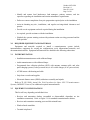
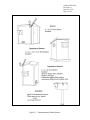
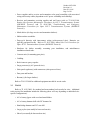
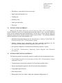
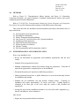
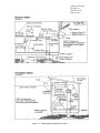
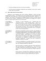
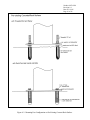
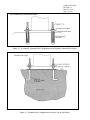
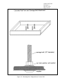
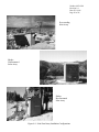
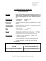
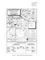
QUALITY ASSURANCE/QUALITY CONTROL DOCUMENTATION SERIES
TITLE
INSTALLATION AND SITE DOCUMENTATION FOR OPTICAL
MONITORING EQUIPMENT
TYPE
STANDARD OPERATING PROCEDURE
NUMBER
4070
DATE
JULY 1996
AUTHORIZATIONS
TITLE
NAME
ORIGINATOR
Gloria S. Mercer
PROJECT MANAGER
James H. Wagner
PROGRAM MANAGER
David L. Dietrich
QA MANAGER
Gloria S. Mercer
SIGNATURE
OTHER
REVISION HISTORY
REVISION
NO.
CHANGE
DESCRIPTION
DATE
AUTHORIZATIONS
Number 4070
Revision 0
Date JUL 1996
Page i of i
TABLE OF CONTENTS
Section
Page
1.0
PURPOSE AND APPLICABILITY
1
2.0
RESPONSIBILITIES
1
2.1
2.2
2.3
2.4
2.5
1
1
2
2
2
3.0
4.0
Program Manager
Project Manager
Field Specialist
Data Analyst
Local (On-Site) Contact
REQUIRED EQUIPMENT AND MATERIALS
3
3.1
3.2
3
3
Equipment and Materials Required for Nephelometer Installations
Equipment and Materials Required for Transmissometer Installations
METHODS
5
4.1
4.2
4.3
4.4
5
6
6
6
Site Preparation and Communication
Installation Methods and Procedures
Operator Training
Site Documentation and Documentation Archival
Number 4070
Revision 0
Date JUL 1996
Page 1 of 6
1.0
PURPOSE AND APPLICABILITY
This standard operating procedure (SOP) outlines the general procedures regarding
installation and site documentation of optical monitoring instrumentation operated according to
IMPROVE Protocol. Optical monitoring sites include those equipped with an Optec LPV
transmissometer and/or Optec NGN nephelometer.
To assure quality data capture and minimize data loss, site installation and documentation
procedures include:
• Installing the instrumentation, shelters, and support components in a standard
configuration to ease data collection, troubleshooting, and servicing.
• Performing thorough on-site specification measurements.
• Documenting site specification measurements and other site-related information.
The following technical instructions provide detailed information regarding installing optical
monitoring equipment or documenting optical site information:
• TI 4070-3000
Installation of Optec NGN-2 Nephelometer Systems (IMPROVE
Protocol)
• TI 4070-3001
Site Documentation for Optec NGN-2 Nephelometer Systems
• TI 4070-3010
Installation and Site Documentation for
Transmissometer Systems (IMPROVE Protocol)
2.0
RESPONSIBILITIES
2.1
PROGRAM MANAGER
Optec
LPV-2
The program manager shall review site preparation, installation requirements, and the
installation schedule with the project manager.
2.2
PROJECT MANAGER
The project manager shall:
• Review site preparation, installation requirements, and the installation schedule with the
program manager and/or the project-specific Contracting Officer's Technical
Representative (COTR) as required.
• Schedule the system installation.
• Review final site configuration plans presented by the field specialist.
• Review the completed site documentation forms for completeness and accuracy.
Number 4070
Revision 0
Date JUL 1996
Page 2 of 6
2.3
FIELD SPECIALIST
The field specialist shall:
• Review the installation with the project manager.
• Coordinate with on-site personnel regarding the installation location, schedule,
installation assistance, and availability of materials.
• Ship all required equipment to the site.
• Install the optical systems.
• Perform an installation calibration or field audit.
• Schedule and conduct an operator training session.
• Complete all site documentation.
• Provide completed site documentation to the data analyst.
2.4
DATA ANALYST
The data analyst shall:
• Verify transmission of data from the system upon completion of the installation.
• Enter all site documentation into the Quality Assurance Database.
• File all hard copy site documentation provided by the field specialist.
2.5
LOCAL (ON-SITE) CONTACT
The local contact shall:
• Review site preparation and installation requirements with the field specialist.
• Identify and contact local landowners, land managers, primary contacts, and site
operators regarding site installation and routine maintenance requirements.
• Perform or ensure completion of any site preparation required prior to the installation.
• Assist in obtaining any site-, installation-, and regular servicing-related clearances and
permits.
• Provide on-site equipment and tools required during the installation.
• As required, provide assistance with the installation.
• Schedule the operator training session with pertinent routine servicing personnel and the
field specialist.
Number 4070
Revision 0
Date JUL 1996
Page 3 of 6
3.0
REQUIRED EQUIPMENT AND MATERIALS
3.1
EQUIPMENT AND
INSTALLATIONS
MATERIALS
REQUIRED
FOR
NEPHELOMETER
• Optec NGN-2 ambient nephelometer with extra lamps
• Rohn tower, base plate, and hardware
• Solar radiation and precipitation shield
• Precipitation hood
• Nephelometer datalogging and support subsystem
• Span gas calibration system
• Ambient air temperature and relative humidity sensor in force-aspirated shield
• AC power line and telephone line
• Complete set of installation tools
• A camera loaded with color print film
• Laptop computer equipped with PROCOMM
• Replacement connector kit
• Telephone line simulator
• Topographic maps of the area
• Information documented during the site selection process
• NGN-2 Nephelometer Site Documentation Form
• Site Operator's Manual for Nephelometer Systems
• Complete set of standard operating procedures and technical instructions regarding
annual site visit procedures, calibration of monitoring systems, replacing and shipping
optical components, monitoring system diagrams, site documentation, and operator
maintenance procedures
• Pen or pencil
3.2
EQUIPMENT AND MATERIALS REQUIRED FOR TRANSMISSOMETER
INSTALLATIONS
• Installation transmissometer with calibrated lamps
Number 4070
Revision 0
Date JUL 1996
Page 4 of 6
• Audit transmissometer with calibrated lamps
• Programmed data collection platform (DCP) with antenna, antenna cable, and solar
panel charging system or AC-trickle charger
• AT/RH sensor with housing and cable
• Strip chart recorder and supplies
• Electronic distance meter (EDM) with mirror assembly and tripods
• Receiver and transmitter shelters with anchor assemblies
• Receiver and transmitter mounting posts and alti-azimuth bases
• Window/hood assemblies
• Terminal strip board
• Power supplies and/or solar panel assemblies
• Metal shelves for larger shelters
• Shelter anchor assemblies
• Deep-cycle batteries for solar-powered installations
• Hardware for shelter assembly, post installation, and miscellaneous installation-related
tasks
• Miscellaneous servicing supplies, as detailed in TI 4115-3000, Annual Site Visit
Procedures for Optec LPV-2 Transmissometer Systems (IMPROVE Protocol), TI 41103100, Routine Site Operator Maintenance Procedures for LPV-2 Transmissometer
Systems (IMPROVE Protocol), and TI 4110-3300, Troubleshooting and Emergency
Maintenance Procedures for Optec LPV-2 Transmissometer Systems (IMPROVE
Protocol)
• Concrete mix
• Caulking
• Rock/concrete epoxy capsules
• Surge protectors
• Solar panel regulators
• Dust pan, brushes, and broom
• AC or battery jigsaw with wood and metal blades
Number 4070
Revision 0
Date JUL 1996
Page 5 of 6
• AC or battery hammer drill with 5/8" hammer bit
• Hand sledge hammer and 5/8" star drill
• Wheelbarrow
• Wood saw
• Topographic maps of the area
• Ruler and protractor
• Photographs of sites, sight path, shelters, equipment configurations, etc.
• Information documented during the site selection process
• Transmissometer Site Description Sheet
• Site Map and Site Specifications Sheet
• Site Operator's Manual for Transmissometer Monitoring Systems
• Complete set of standard operating procedures and technical instructions regarding
annual site visit procedures, calibration of monitoring systems, replacing and shipping
optical components, monitoring system diagrams, site documentation, and operator
maintenance procedures
• Pen or pencil
4.0
METHODS
This section includes four (4) major subsections that describe installation and
documentation procedures applied to optical instruments:
4.1
4.2
4.3
4.4
4.1
Site Preparation and Communication
Installation Methods and Procedures
Operator Training
Site Documentation and Documentation Archival
SITE PREPARATION AND COMMUNICATION
Site preparation includes reviewing installation requirements with the local contact and
scheduling all site preparation activities, including obtaining permission from landowners to access
the monitoring location, determining site operators, and ensuring that all other necessary
installation assistance is obtained.
The project manager schedules a site installation visit. The field technician schedules
assistance from on-site personnel (such as obtaining required tools and equipment) and an operator
training session.
Number 4070
Revision 0
Date JUL 1996
Page 6 of 6
4.2
INSTALLATION METHODS AND PROCEDURES
Nephelometer systems require installation of a tower, the nephelometer (with solar
radiation and precipitation shield, precipitation hood, and AT/RH sensor) and support system
components (datalogging and control subsystem, and span gas calibration system). Specific
installation requirements are detailed in TI 4100-3375, Replacing and Shipping Nephelometer
System Components. In addition, AC line power and a telephone line must be connected. After
installation of the instrumentation, the entire system operation must be calibrated and verified.
Transmissometer systems require installation of shelters for both the transmitter and
receiver units, mounting posts, the specific transmissometer components (transmitter and
receiver) and support system components (alti-azimuth bases, terminal strip, AT/RH sensor, DCP
and antenna, and strip chart recorder). Specific installation requirements are detailed in TI 41103375, Replacing and Shipping Transmissometer Components. In addition, either AC line power
or DC solar power installation is required. After installation of the instrumentation, the entire
system operation must be verified, and sight path distance measured.
4.3
OPERATOR TRAINING
Upon completion of the optical installation and system operation verification, all operators,
back-up operators, and any other involved or interested on-site personnel are trained according to
the procedures in TI 4115-3000, Annual Site Visit Procedures for Optec LPV-2 Transmissometer
Systems (IMPROVE Protocol) or TI 4115-3005, Annual Site Visit Procedures for Optec NGN-2
Nephelometer Systems (IMPROVE Protocol). Operators are trained in an overview of the
monitoring program, instrument function and theoretical operation, component overview, routine
servicing, and troubleshooting procedures. The site operator's manual for the appropriate
instrumentation is reviewed and a copy is left with the site operators.
4.4
SITE DOCUMENTATION AND DOCUMENTATION ARCHIVAL
The field specialist completes site documentation including a site visit trip report, site
specifications, geographic reference including landmarks, and location of monitoring equipment.
Photographic documentation is also collected of the instrumentation.
QUALITY ASSURANCE/QUALITY CONTROL DOCUMENTATION SERIES
TITLE
INSTALLATION AND SITE DOCUMENTATION FOR OPTEC LPV-2
TRANSMISSOMETER SYSTEMS (IMPROVE PROTOCOL)
TYPE
TECHNICAL INSTRUCTION
NUMBER
4070-3010
DATE
FEBRUARY 1994
AUTHORIZATIONS
TITLE
NAME
ORIGINATOR
Ivar J. Rennat
PROJECT MANAGER
James H. Wagner
PROGRAM MANAGER
David L. Dietrich
QA MANAGER
Gloria S. Mercer
SIGNATURE
OTHER
REVISION HISTORY
REVISION
NO.
0.1
CHANGE
DESCRIPTION
Minor text changes and updated format.
DATE
July 1996
AUTHORIZATIONS
Number 4070-3010
Revision 0.1
Date JUL 1996
Page i of ii
TABLE OF CONTENTS
Section
Page
1.0
PURPOSE AND APPLICABILITY
1
2.0
RESPONSIBILITIES
1
2.1
2.2
2.3
2.4
2.5
1
1
2
2
2
3.0
4.0
REQUIRED EQUIPMENT AND MATERIALS
3
3.1
3.2
3.3
3.4
3.5
3
3
5
6
6
Instrumentation
Equipment Configurations
Tools
Installation Materials
Site Documentation Materials
METHODS
4.1
4.2
4.3
4.4
4.5
4.6
4.7
4.8
4.9
5.0
Program Manager
Project Manager
Field Specialist
Data Analyst
Local (On-Site) Contact
7
Site Preparation and Communication
Mounting Post Installation
Shelter Transportation and Installation
Line-Power (AC) and Solar Power (DC) System Installation
Installation of Instrumentation
Sight Path Distance Measurement
System Operation Verification
Operator Training
Site Documentation and Documentation Archival
REFERENCES
7
9
13
14
17
22
22
22
22
26
LIST OF FIGURES
Figure
Page
3-1
Transmissometer Shelter Options
4
4-1
Monitoring Component Placement
8
4-2
Mounting Post Configuration on Pre-Existing Concrete/Rock Surface
10
4-3
Mounting Post Configuration on Concrete Pier in Soil Surface
11
4-4
Mounting Post Configuration on Concrete Pad
12
Number 4070-3010
Revision 0.1
Date JUL 1996
Page ii of ii
LIST OF FIGURES (CONTINUED)
Figure
Page
4-5
Receiver Station Line Power (AC) Configuration Diagram
15
4-6
Transmitter Station Line Power (AC) Configuration Diagram
16
4-7
Receiver Station Solar Power (DC) Configuration Diagram
18
4-8
Transmitter Station Solar Power (DC) Configuration Diagram
19
4-9
Solar Panel Array Installation Configurations
20
4-10 Example Transmissometer Site Description Sheet
24
4-11 Example Site Map and Site Specification Sheet
25
Number 4070-3010
Revision 0.1
Date JUL 1996
Page 1 of 26
1.0
PURPOSE AND APPLICABILITY
This technical instruction (TI) describes the procedures for installation and site
documentation of Optec LPV-2 transmissometer stations operated according to IMPROVE
Protocol. The purpose of this TI is to assure quality data capture and minimize data loss by:
• Installing the instrumentation, shelters, and support components in a standard
configuration to assure ease in data collection, troubleshooting, and servicing.
• Performing thorough on-site specification measurements.
• Documenting site specification measurements and other site-related information.
This TI is referenced from Standard Operating Procedure (SOP) 4070, Installation and Site
Documentation for Optical Monitoring Equipment. The following SOPs and TIs are referenced
in this document:
• TI 4050-3010
Site Selection for Optec LPV-2 Transmissometer Systems
• TI 4110-3350
Transmissometer Monitoring System Diagrams and Component
Descriptions
• TI 4110-3375
Replacing and Shipping Transmissometer Components
• TI 4115-3000
Annual Site Visit Procedures for Optec LPV-2 Transmissometer
Systems (IMPROVE Protocol)
• TI 4200-2100
Calibration
Protocol)
• SOP 4710
Transmissometer Field Audit Procedures
2.0
RESPONSIBILITIES
2.1
PROGRAM MANAGER
of
Optec
LPV-2
Transmissometers
(IMPROVE
The program manager shall review site preparation, installation requirements, and the
installation schedule with the project manager.
2.2
PROJECT MANAGER
The project manager shall:
• Review the site preparation, installation requirements, and the installation schedule with
the program manager and/or the project-specific Contracting Officer's Technical
Representative (COTR) as required.
• Review final site configuration plans presented by the field specialist.
• Schedule the system installation.
Number 4070-3010
Revision 0.1
Date JUL 1996
Page 2 of 26
2.3
FIELD SPECIALIST
The field specialist shall:
• Review final site preparation and installation plans with the project manager.
• Inform the site-specific local contact of the installation schedule.
• Review the determined site preparation and installation requirements with the local
contact, as required.
• Maintain communications with the local contact during site preparation. Verify that all
required site preparation is completed prior to installation.
• Verify that all required clearances and permissions relating to the specific site, system
installation, and regular servicing have been obtained prior to the installation.
• Schedule and arrange for any on-site assistance needed during the installation.
• Install the transmissometer system according to this TI.
• Complete all site documentation according to this TI.
• Perform all applicable tasks for annual site visits according to TI 4115-3000, Annual Site
Procedures for Optec LPV-2 Transmissometer Systems (IMPROVE Protocol).
• Perform an installation field audit according to SOP 4710, Transmissometer Field Audit
Procedures.
• Schedule an operator training session for all identified operators and conduct the training
according to the procedures described in TI 4115-3000.
• Provide completed site documentation to the data analyst.
2.4
DATA ANALYST
The data analyst shall:
• Verify transmission of data from the system upon completion of the installation.
• Enter all site documentation into the Quality Assurance Database.
• File all hard copy site documentation provided by the field specialist.
2.5
LOCAL (ON-SITE) CONTACT
The local contact shall:
• Review site preparation and installation requirements with the field specialist.
Number 4070-3010
Revision 0.1
Date JUL 1996
Page 3 of 26
• Identify and contact local landowners, land managers, primary contacts, and site
operators regarding site installation and routine maintenance requirements.
• Perform or ensure completion of any site preparation required prior to the installation.
• Assist in obtaining any site-, installation-, and regular servicing-related clearances and
permits.
• Provide on-site equipment and tools required during the installation.
• As required, provide assistance with the installation.
• Schedule the operator training session with pertinent routine servicing personnel and the
field specialist.
3.0
REQUIRED EQUIPMENT AND MATERIALS
Equipment and materials required to install a transmissometer system include
instrumentation, equipment for varying site configurations, tools, informational materials, and
documentation materials. Equipment and materials are detailed in the following subsections.
3.1
INSTRUMENTATION
• Installation transmissometer with calibrated lamps
• Audit transmissometer with calibrated lamps
• Programmed data collection platform (DCP) with antenna, antenna cable, and solar
panel charging system (if solar-powered site) or AC-trickle charger (if AC-powered site)
• AT/RH sensor with housing and cable
• Strip chart recorder and supplies
• Electronic distance meter (EDM) with mirror assembly and tripods
Refer to TI 4115-3000, Annual Site Visit Procedures for Optec LPV-2 Transmissometer
Systems (IMPROVE Protocol) for additional required instrumentation.
3.2
EQUIPMENT CONFIGURATIONS
This list will vary depending on individual sites:
• Receiver and transmitter shelters (assembled or disassembled, dependent on site
installation constraints). Refer to Figure 3-1 for standard transmissometer shelters.
• Receiver and transmitter mounting posts and alti-azimuth bases.
• Window/hood assemblies.
• Terminal strip board.
Number 4070-3010
Revision 0.1
Date JUL 1996
Page 4 of 26
Figure 3-1. Transmissometer Shelter Options.
Number 4070-3010
Revision 0.1
Date JUL 1996
Page 5 of 26
• Power supplies and/or receiver and transmitter solar panel assemblies with associated
wiring and security cables (dependent on AC-power availability and reliability).
• Receiver and transmitter servicing supplies and tool boxes (refer to TI 4110-3100,
Routine Site Operator Maintenance Procedures for LPV-2 Transmissometer Systems
(IMPROVE Protocol) and TI 4110-3300, Troubleshooting and Emergency
Maintenance Procedures for Optec LPV-2 Transmissometer Systems (IMPROVE
Protocol)).
• Metal shelves (for large receiver and transmitter shelters).
• Shelter anchor assemblies.
• Deep-cycle batteries with interconnect wiring (solar-powered sites). Batteries are
typically purchased locally. Refer to TI 4115-3000, Annual Site Visit Procedures for
Optec LPV-2 Transmissometer Systems (IMPROVE Protocol).
• Hardware for shelter assembly, mounting post installation, and miscellaneous
installation-related tasks.
• Concrete mix (for mounting post piers).
• Caulking.
• Rock/concrete epoxy capsules.
• Surge protector(s) (AC-powered sites).
• Solar panel regulator(s) with connectors (solar-powered sites).
• Dust pans and brushes.
• Broom(s) (for larger shelters).
Refer to TI 4115-3000 for additional equipment needed for on-site tasks.
3.3
TOOLS
Refer to TI 4115-3000, for standard and non-standard tools needed at sites. Additional
tools required for installation include the following (these will vary depending on individual sitespecific configurations):
• AC or battery jigsaw with wood and metal blades
• AC or battery hammer drill with 5/8" hammer bit
• Hand sledge hammer and 5/8" star drill
• Large pry bar (can usually be borrowed on-site)
• Shovel (can usually be borrowed on-site)
Number 4070-3010
Revision 0.1
Date JUL 1996
Page 6 of 26
• Wheelbarrow (can usually be borrowed on-site)
• Single-wheel field transport cart
• Caulking gun
• Extension cords
• Staple gun with staples
• Wood saw
3.4
INSTALLATION MATERIALS
Refer to TI 4115-3000, Annual Site Visit Procedures for Optec LPV-2 Transmissometer
Systems (IMPROVE Protocol) for standard materials needed when at a site. Note that calibration
memos for the installation and audit transmissometers will need to be revised when the sight path
length has been measured with the electronic distance meter (EDM). The following additional
materials should also be taken when installing a site:
• Information documented during the site selection process. Refer to TI 4050-3010, Site
Selection for Optec LPV-2 Transmissometer Systems.
• Manuals, technical notes, instructions, and other applicable information for the
previously listed instrumentation and equipment (Sections 3.1 and 3.2).
• Site Operator's Manual for Transmissometer Monitoring Systems (3 copies).
• TI 4110-3350, Transmissometer Monitoring System Diagrams and Component
Descriptions.
3.5
SITE DOCUMENTATION MATERIALS
The following materials are generally required to complete the site documentation process:
• TI 4115-3000, Annual Site Visit Procedures for Optec LPV-2 Transmissometer Systems
(IMPROVE Protocol)
• Transmissometer Network Servicing Site Visit Trip Report and Data Sheet
• On-site documentation acquired by the field specialist during installation
• Topographic maps of the area
• Ruler and protractor
• Photographs of the sites, shelters, sight path, equipment configurations, etc.
Number 4070-3010
Revision 0.1
Date JUL 1996
Page 7 of 26
4.0
METHODS
Refer to Figure 3-1, Transmissometer Shelter Options, and Figure 4-1, Monitoring
Component Placement, for general diagrams of standard transmissometer shelters and system
component placement and configuration.
Refer to TI 4110-3350, Transmissometer Monitoring System Diagrams and Component
Descriptions, for specific diagrams and descriptions of individual system components.
This section describes site installation and documentation procedures and includes nine (9)
major subsections:
4.1
4.2
4.3
4.4
4.5
4.6
4.7
4.8
4.9
4.1
Site Preparation and Communication
Mounting Post Installation
Shelter Transportation and Installation
Line-Power (AC) and Solar Power (DC) System Installation
Installation of Instrumentation
Sight Path Distance Measurement
System Operation Verification
Operator Training
Site Documentation and Documentation Archival
SITE PREPARATION AND COMMUNICATION
Prior to any installation visit:
• Review the determined site preparation and installation requirements with the local
contact.
• Schedule all site preparation activities.
• Maintain communications with the local contact during site preparation. Verify that all
required site preparation is completed prior to the installation.
• Document the primary site operator(s) and backup operator(s).
• Obtain permission from private or public landowners to access the monitoring location
for installation and training.
• Schedule the site installation visit and operator training session. (Typically an
installation will require approximately 3-4 on-site work days. Training should be
scheduled in the latter part of the week when the system is fully installed and
operational).
• Arrange for any necessary installation assistance, as well as tools and/or equipment (e.g.,
shovels, wheelbarrow, water containers).
Once on-site:
• Inspect any site preparation that has been done.
Number 4070-3010
Revision 0.1
Date JUL 1996
Page 8 of 26
Figure 4-1. Monitoring Component Placement.
Number 4070-3010
Revision 0.1
Date JUL 1996
Page 9 of 26
• Verify that all shipped items have arrived in good condition.
• Verify the proposed installation configuration and scheduling for the operator training
session with on-site personnel.
4.2
MOUNTING POST INSTALLATION
Continuous, correct transmitter and receiver telescope alignment is critical for proper
transmissometer operation. The transmitter and receiver mounting posts must be installed in such
a manner that any movement due to earth movement, temperature fluctuations, vibration, etc. is
minimized. The procedures for mounting post installation depend on the type of surface material
to which the post is mounted. Mounting posts can be attached to pre-existing rock or concrete
surface, to a concrete pier in the soil, or to a concrete pad.
ATTACHMENT
TO PRE-EXISTING
ROCK OR
CONCRETE
SURFACE
Typically, it is most convenient to use ½" diameter bolts with
concrete/rock inserts. If the mounting surface is uneven, use
threaded rods instead of bolts; this method allows leveling of the
post. In cases where the rock or concrete is not strong enough for
inserts to seat securely, rock/concrete epoxy capsules should be used
with threaded rod sections. Refer to Figure 4-2, Mounting Post
Configuration on Pre-Existing Concrete/Rock Surface, for diagrams
of these various mounting methods.
ATTACHMENT
TO CONCRETE
PIER IN
SOIL
The hole size and amount of concrete used may vary depending on
the type of soil and ease of hole excavation. Typically, a concrete
pier should be approximately 1.5 feet in diameter and 2 feet deep.
J- (foundation) bolts of ½" diameter are set into the wet concrete
with a wood template. Approximately 8 to 12 hours are usually
required before the concrete is firm enough for post-attachment.
Refer to Figure 4-3, Mounting Post Configuration in Concrete Pier
in Soil Surface, for a diagram of a typical concrete pier and post
attachment configuration. Leveling of the post is achieved by
adjustment of the lower set of nuts.
ATTACHMENT
TO CONCRETE
PAD
Concrete pad installations are normally performed on roof surfaces
or at locations where the ground surface cannot be altered or where
other post attachment methods are impractical.
Due to the weight, it is advisable to pour the concrete pad after the
form has been placed at the installation site. Pad size will vary
according to individual site constraints and configurations. If a small
shelter is to be used, the pad is typically large enough to support the
shelter.
Refer to Figure 4-4, Mounting Post Configuration on Concrete Pad,
for diagrams of a typical concrete pad form and bolt attachment. If a
shelter is to be attached to the pad, additional bolts are required.
Number 4070-3010
Revision 0.1
Date JUL 1996
Page 10 of 26
Figure 4-2. Mounting Post Configuration on Pre-Existing Concrete/Rock Surface.
Number 4070-3010
Revision 0.1
Date JUL 1996
Page 11 of 26
Figure 4-2. (Continued) Mounting Post Configuration on Pre-Existing Concrete/Rock Surface.
Figure 4-3. Mounting Post Configuration on Concrete Pier in Soil Surface.
Number 4070-3010
Revision 0.1
Date JUL 1996
Page 12 of 26
Figure 4-4. Mounting Post Configuration on Concrete Pad.
Number 4070-3010
Revision 0.1
Date JUL 1996
Page 13 of 26
4.3
SHELTER TRANSPORTATION AND INSTALLATION
SHELTER
TRANSPORTATION
The method(s) of long-distance and on-site transportation of
transmissometer shelters depend on the following factors:
• Type(s) of shelter(s)
• Disassembled or assembled shelter(s)
• Distances
• Shipping (trucking) company limitations
• Site accessibility
Large shelters are usually transported by trailers or, if disassembled,
can also be shipped with trucking companies. Small shelters can be
transported by truck, trailer, or be shipped.
On-site transportation of the shelters to the installation locations is
primarily dependent on site accessibility. If vehicle access to the site
is not possible, the shelters or disassembled sections can be
transported by carrying, handcart, or wheeled trail transport cart. If
site access is very difficult, use of a helicopter should be considered.
SHELTER
INSTALLATION
The general procedures for shelter installation are as follows:
• Verify that preparations for attachment of the instrument
mounting post have been completed.
• Place the shelter (or shelter floor section, if disassembled) on
concrete blocks or piers. Verify that the floor is level and that the
shelter correctly oriented with respect to the transmitter sight
path.
• Assemble the shelter
window/hood assembly.
(if
disassembled)
and
attach
the
• Install the instrument mounting post. Verify that there is at least
½" clearance between the post and the edge of the shelter floor
hole to ensure that shelter vibration is not transferred to the post
and instrument.
A rubber boot is placed around the post and attached to the floor to
prevent dust, insects, snow, rodents, etc. from entering the shelter.
Adjust post height for correct instrument/window alignment and fill
the post with sand to minimize post movement due to thermal
contraction/expansion.
Number 4070-3010
Revision 0.1
Date JUL 1996
Page 14 of 26
• Anchor the shelter to the ground with eyehooks, turnbuckles, and
the appropriate ground attachment method. The method of
attaching the anchor assembly depends on the ground surface
type. These are outlined as follows:
4.4
-
Soil (clay, sand, silt, etc.) - Use soil screw anchors (length of
anchor is dependant on hardness of soil).
-
Rocky soil or soil too hard for screw anchors - Use steel
construction stakes.
-
Rock - Use rock/concrete inserts similar to the type used for
mounting post attachment to rock/concrete.
-
Concrete - The shelter can be directly attached to the
concrete using the above-mentioned rock/concrete inserts
and bolts.
LINE-POWER (AC) AND SOLAR POWER (DC) SYSTEM INSTALLATION
Refer to Figures 4-5 and 4-6, Receiver Station and Transmitter Station Line Power (AC)
Configuration Diagrams, and Figures 4-7 and 4-8, Receiver Station and Transmitter Station Solar
Power (DC) Configuration Diagrams, for diagrams of standard power system configurations and
related components. Diagrams and descriptions of individual components are contained in TI
4110-3350, Transmissometer Monitoring System Diagrams and Component Descriptions.
LINE-POWER
(AC) SYSTEM
INSTALLATION
Install the various components according to Figures 4-5 and 4-6,
Receiver Station and Transmitter Station Line Power (AC)
Configuration Diagrams.
Also refer to TI 4110-3350,
Transmissometer Monitoring System Diagrams and Component
Descriptions
and
component-specific
installation/operation
instructions.
Power system components should be installed in such a manner that
servicing checks and/or maintenance procedures can easily be
performed.
SOLAR-POWER
(DC) SYSTEM
INSTALLATION
Refer to Figure 4-9, Solar Panel Array Installation Configurations,
for photographs of standard solar panel array installation
configurations. Guidelines for the selection of array mounting
configurations are contained in TI 4050-3010, Site Selection for
Optec LPV-2 Transmissometer Systems.
The standard receiver station solar panel array is comprised of two
large Solarex SX-56 solar panels which charge the four NAPA
Group 27 deep-cycle batteries that provide receiver system power.
A third smaller Solarex SX-10 solar panel provides power to the
data collection platform (DCP).
Number 4070-3010
Revision 0.1
Date JUL 1996
Page 15 of 26
Figure 4-5. Receiver Station Line Power (AC) Configuration Diagram.
Number 4070-3010
Revision 0.1
Date JUL 1996
Page 16 of 26
Figure 4-6. Transmitter Station Line Power (AC) Configuration Diagram.
Number 4070-3010
Revision 0.1
Date JUL 1996
Page 17 of 26
The standard transmitter station solar panel array is comprised of three
large Solarex SX-56 solar panels which charge the four NAPA
Group 27 deep-cycle batteries that provide transmitter system
power.
Install the various components according to Figures 4-7 and 4-8,
Receiver Station and Transmitter Station Solar Power (DC)
Configuration Diagrams.
Also refer to TI 4110-3350,
Transmissometer Monitoring System Diagrams and Component
Descriptions
and
component-specific
installation/operation
instructions.
A security cable should be run through the solar panel frames and
secured inside the shelter to deter theft of the panels.
Install the four deep-cycle batteries and interconnect wiring
according to TI 4110-3350.
4.5
INSTALLATION OF INSTRUMENTATION
Refer to TI 4110-3350 for depictions of the various instruments and related equipment and
standard installation configurations. Installation procedures for transmissometer components,
data collection platform (DCP), strip chart recorder, and air temperature/relative humidity
(AT/RH) sensor are described in TI 4110-3375, Replacing and Shipping Transmissometer
Components.
TRANSMITTER
AND RECEIVER
ALTI-AZIMUTH
BASE
INSTALLATION
Attach the transmitter and receiver alti-azimuth bases to the
respective mounting posts. Verify that there is adequate horizontal
adjustment tension when the transmitter and receiver telescopes are
properly aligned. Non-level sight paths may require placing
washers underneath the front or back portions of the bases to ensure
proper vertical alignment adjustment.
TERMINAL STRIP
INSTALLATION
(RECEIVER
SHELTER)
Attach the terminal strip to the shelter wall close to where the
receiver computer, strip chart recorder, and data collection platform
(DCP) will be located. Ensure that the terminal strip is readily
accessible for servicing checks.
AT/RH SENSOR
INSTALLATION
(RECEIVER
SHELTER)
The AT/RH sensor should be mounted close to the roofline of the
shelter and be far enough from the roof (or any other surface) to
provide representative ambient AT/RH measurements. The AT/RH
cable is routed from the sensor into the shelter and connected to the
DCP. If possible, install the sensor near the DCP antenna in order
that both cables can be routed into the shelter together.
Refer to TI 4110-3375, Replacing and Shipping Transmissometer
Components.
Number 4070-3010
Revision 0.1
Date JUL 1996
Page 18 of 26
Figure 4-7. Receiver Station Solar Power (DC) Configuration Diagram.
Number 4070-3010
Revision 0.1
Date JUL 1996
Page 19 of 26
Figure 4-8. Transmitter Station Solar Power (DC) Configuration Diagram.
Number 4070-3010
Revision 0.1
Date JUL 1996
Page 20 of 26
Free-standing
Solar Array
Shelter
Wall-mounted
Solar Array
Shelter
Roof-mounted
Solar Array
Figure 4-9. Solar Panel Array Installation Configurations.
Number 4070-3010
Revision 0.1
Date JUL 1996
Page 21 of 26
DCP AND
ANTENNA
INSTALLATION
(RECEIVER
SHELTER)
Mount the DCP antenna near the roofline of the shelter. If possible,
the antenna should be near the AT/RH sensor in order that both
cables can be routed into the shelter together. Antenna installation
and orientation specifications and procedures are outlined in the
Handar DCP Operating and Servicing Manual for each model of
DCP (Handar, 1983, 1986, and 1988). Install the DCP according to
the procedures described in Section 4.4, Line Power (AC) and Solar
Power (DC) System Installation, and TI 4110-3375, Replacing and
Shipping Transmissometer Components.
TRANSMISSOMETER
INSTALLATION
Install the transmitter and receiver unit components according to
the procedures described in TI 4110-3375.
STRIP CHART
RECORDER
INSTALLATION
(RECEIVER
SHELTER)
Install the strip chart recorder according to the procedures described
in TI 4110-3375.
GENERAL
INSTALLATION
GUIDELINES
General guidelines during the placement and installation of
instrumentation, related equipment, and supplies are as follows:
• Place items in an orderly, space-efficient manner.
• Group related items/instrumentation together.
• Ensure that all instrument displays/indicators are easily and clearly
visible.
• Ensure that all switches, dials, etc., are labeled and clearly visible,
and easily accessible.
• Ensure that all connectors/connections are labeled and easily
accessible.
• In larger shelters, install a shelf for storage of miscellaneous items.
• Upon installation, verify correct operation of each system
component. Operation verification for the entire system is
performed after measurement of the sight path distance.
• Secure excess and/or loose wiring with wire ties.
• Caulk any shelter holes or cracks around the window/hood
assembly, etc. to prevent dust, precipitation, insects, etc. from
entering the shelter.
Number 4070-3010
Revision 0.1
Date JUL 1996
Page 22 of 26
4.6
SIGHT PATH DISTANCE MEASUREMENT
Measurement of the sight path distance is made with the electronic distance meter (EDM).
Refer to the EDM operating manual (Hewlett Packard) for operational procedures.
The distance measurement is made from the front of the receiver telescope tube to the front
of the transmitter telescope tube. The measurement should be repeated at least three times.
Once the distance measurement has been made, the distance is communicated to the project
manager in order that the transmissometer calibration numbers can be recalculated using the
accurate distance value.
The recalculated calibration numbers are communicated to the on-site field specialist, and
the correct calibration number is dialed in on the receiver computer.
4.7
SYSTEM OPERATION VERIFICATION
Once the instrument settings and system timing have been set at the transmitter and
receiver, system operation can be verified. Operation verification and documentation is
performed according to the procedures described in TI 4115-3000, Annual Site Visit Procedures
for Optec LPV-2 Transmissometer Systems (IMPROVE Protocol). Also, all other pertinent
operational- and servicing-related tasks and procedures are performed as described in the aforementioned TI 4115-3000.
4.8
OPERATOR TRAINING
Upon completion of the installation and system operation verification, all operators, backup operators, and any other involved or interested on-site personnel are trained according to the
procedures outlined in TI 4115-3000. The Site Operator's Manual for Transmissometer
Monitoring Systems is reviewed and a copy left at both transmitter and receiver sites. The third
copy is to be kept at the office of on-site personnel.
4.9
SITE DOCUMENTATION AND DOCUMENTATION ARCHIVAL
ON-SITE
DOCUMENTATION
On-site documentation is performed by the field specialist as
follows:
• Completion of the Transmissometer Network Servicing Site Visit
Trip Report and Data Sheet
• Photographic documentation of the following:
-
Shelters, various views
-
Windows and hoods
-
Antenna with mount
-
AT/RH sensor with mount
Number 4070-3010
Revision 0.1
Date JUL 1996
Page 23 of 26
POST-INSTALLATION
TRIP SITE
DOCUMENTATION
AND ARCHIVAL
-
Shelter supports and mounting post attachments
-
Sight path, receiver to transmitter, and transmitter to
receiver, at various zoom settings (35 mm, 50 mm, 135 mm)
-
Shelter interior configurations/layouts
-
Computer and strip chart
-
Terminal strip board
-
Receiver and transmitter telescopes on mounts
-
DCP and associated wiring
-
Batteries and solar panel regulator (solar-powered sites)
-
Power supply and surge protector (line-powered sites)
-
Solar panels (solar-powered sites)
•
Documentation of miscellaneous information necessary to
complete the Transmissometer Site Description Sheet and the
Site Map and Site Specifications Sheet. Refer to Figure 410, Example Transmissometer Site Description Sheet and
Figure 4-11, Example Site Map and Site Specifications
Sheet.
Within one week after return from the installation trip, the following
documentation is completed:
• Completion of the Transmissometer Site Description and the Site
Map and Site Specifications Sheets
• Developing of all film from site photographic documentation
Upon completion of this documentation, post-visit procedures, as
described in TI 4115-3000, Annual Site Visit Procedures for Optec
LPV-2 Transmissometer Systems (IMPROVE Protocol), are
performed. Additional procedures, not described in these post-visit
procedures are performed as follows:
• Archival of the Transmissometer Site Description and the Site
Map and Site Specifications Sheets in site-specific operations files
located in the ARS data collection center
• Organization and filing of the site photographic documentation by
the data analyst
Number 4070-3010
Revision 0.1
Date JUL 1996
Page 24 of 26
TRANSMISSOMETER SITE DESCRIPTION
GRAND CANYON NATIONAL PARK
(IN-CANYON SIGHT PATH)
Site Location -
Grand Canyon National Park is located approximately 100 km north of
Flagstaff, Arizona. The transmissometer is located approximately 20 km
east of the park headquarters, along the east rim drive (State Highway
64).
Operational Period -
• Installation Date:
• Removal Date:
Receiver Station -
Located on the canyon rim, adjacent to the north corner of the Yavapai
Museum.
Transmitter Station -
Located at the bottom of the canyon at the north edge of Phantom
Ranch, adjacent to water tank.
Power -
• Receiver Station:
• Transmitter Station:
Sight Path -
Elevation angle approximately -16° from receiver to transmitter.
Elevation difference between receiver and transmitter is 1390 meters.
Beam height is well above terrain features along the entire path.
Siting Constraints -
• Operator Site Access Considerations: Availability of site
operators at transmitter site.
December 13, 1989
Ongoing
Line power
Line power
• Power Considerations: AC line power required on canyon floor.
• Terrain Considerations: Few sight paths from the rim to the
canyon floor exist.
SITE FACTORS POTENTIALLY AFFECTING
TRANSMISSOMETER READINGS
FACTOR
Power outages at receiver due to lightning hits
near the power line.
EFFECT ON DATA/OPERATION
Receiver operation interrupted during power
outages. Transmissometer data are not available
for these periods.
Figure 4-10. Example Transmissometer Site Description Sheet.
Number 4070-3010
Revision 0.1
Date JUL 1996
Page 25 of 26
Figure 4-11. Example Site Map and Site Specification Sheet.
Number 4070-3010
Revision 0.1
Date JUL 1996
Page 26 of 26
5.0
REFERENCES
Handar, Inc., May 1983, Operating and Service Manual for 540A Multiple Access Data
Acquisition System, 560A Hydrologic Data Collection System, and 545 Programming Set.
Handar, Inc., September 1986, Operating and Service manual for 540A-1 Multiple Access Data
Acquisition System, 560A Data Collection System, 570A Expandable Hydromet Data
Acquisition System.
Handar, Inc., March 1988, 570A Data Acquisition System Operating and Service Manual.
Hewlett Packard, The HP 3808A Medium Range Distance Meter.