1
Operating Instructions
Liquiline CM442
Universal four-wire multichannel controller
Operation & settings
BA450C/07/EN/03.10
71099471
Valid as of:
Software version 01.00.00
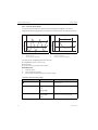
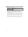
Operation concept
a0012790-en
Fig. 1: Pressing the soft key: selecting the menu directly
a0012791-en
Fig. 2: Turning the navigator: moving the cursor in the
menu
a0012792-en
Fig. 3: Pressing the navigator: launching a function
a0012793-en
Fig. 4: Turning the navigator: selecting a value (e.g. from
a list)
a0012794-en
Fig. 5: Pressing the navigator: accepting the new value
a0012795-en
Fig. 6: Result: new setting is accepted
Liquiline CM442
Table of contents
1
About this manual . . . . . . . . . . 4
5.10 Sensor factory setting (COS61D) . . . . . . . . 49
2
Information on sensors with the
Memosens protocol . . . . . . . . . 5
6
Inputs: Turbidity and solids . . 50
6.1
Temperature format, sensor identification and
damping . . . . . . . . . . . . . . . . . . . . . . . . . . 50
Application and main measured value . . . . 51
Cleaning . . . . . . . . . . . . . . . . . . . . . . . . . . 52
Calibration settings . . . . . . . . . . . . . . . . . . 53
Diagnostics settings . . . . . . . . . . . . . . . . . . 54
Tag control . . . . . . . . . . . . . . . . . . . . . . . . 58
Sensor input factory setting . . . . . . . . . . . . 58
Sensor factory setting . . . . . . . . . . . . . . . . 59
3
Inputs: pH/ORP . . . . . . . . . . . . 6
3.1
3.2
3.3
3.4
3.5
3.6
3.7
3.8
Sensor identification and damping . . . . . . . 6
Temperature and medium compensation (only
pH) . . . . . . . . . . . . . . . . . . . . . . . . . . . . . . 7
Main value and temperature format . . . . . . 8
Cleaning . . . . . . . . . . . . . . . . . . . . . . . . . . 8
Calibration settings . . . . . . . . . . . . . . . . . . 9
Diagnostics settings . . . . . . . . . . . . . . . . . 12
Tag control . . . . . . . . . . . . . . . . . . . . . . . 20
Sensor input factory setting . . . . . . . . . . . 20
4
Inputs: Conductivity . . . . . . . . 21
4.1
Temperature format, sensor identification and
damping . . . . . . . . . . . . . . . . . . . . . . . . . 21
4.2 Operating mode and cell constant . . . . . . 22
4.3 Installation factor (only inductive sensors) . 23
4.4 Concentration table (only inductive
sensors) . . . . . . . . . . . . . . . . . . . . . . . . . . 24
4.5 Main measured value and unit . . . . . . . . . 25
4.6 Temperature compensation . . . . . . . . . . . 26
4.7 Cleaning . . . . . . . . . . . . . . . . . . . . . . . . . 28
4.8 Diagnostics settings . . . . . . . . . . . . . . . . . 29
4.9 Tag control . . . . . . . . . . . . . . . . . . . . . . . 33
4.10 Sensor input factory setting . . . . . . . . . . . 34
4.11 Sensor factory setting (CLS50D only) . . . . 34
5
Inputs: Oxygen . . . . . . . . . . . . 35
5.1
Temperature format, sensor identification and
damping . . . . . . . . . . . . . . . . . . . . . . . . . 35
Main value . . . . . . . . . . . . . . . . . . . . . . . 36
Medium compensation (in the process) . . 37
Polarization voltage (only amperometric
sensors) . . . . . . . . . . . . . . . . . . . . . . . . . . 37
Cleaning . . . . . . . . . . . . . . . . . . . . . . . . . 38
Calibration settings . . . . . . . . . . . . . . . . . 39
Diagnostics settings . . . . . . . . . . . . . . . . . 41
Tag control . . . . . . . . . . . . . . . . . . . . . . . 48
Sensor input factory setting . . . . . . . . . . . 49
5.2
5.3
5.4
5.5
5.6
5.7
5.8
5.9
Endress+Hauser
6.2
6.3
6.4
6.5
6.6
6.7
6.8
7
Inputs: Nitrate. . . . . . . . . . . . . 60
7.1
7.2
7.3
7.4
7.5
7.6
7.7
7.8
Temperature format, sensor identification and
damping . . . . . . . . . . . . . . . . . . . . . . . . . . 60
Application and main measured value . . . . 61
Cleaning . . . . . . . . . . . . . . . . . . . . . . . . . . 62
Calibration settings . . . . . . . . . . . . . . . . . . 62
Diagnostics settings . . . . . . . . . . . . . . . . . . 63
Tag control . . . . . . . . . . . . . . . . . . . . . . . . 67
Sensor input factory setting . . . . . . . . . . . . 68
Sensor factory setting . . . . . . . . . . . . . . . . 68
8
Outputs . . . . . . . . . . . . . . . . . . 69
8.1
8.2
Current outputs . . . . . . . . . . . . . . . . . . . . 69
Alarm relay and optional relays . . . . . . . . . 72
9
Additional functions . . . . . . . . 77
9.1
9.2
9.3
Limit switch . . . . . . . . . . . . . . . . . . . . . . . 77
Controller . . . . . . . . . . . . . . . . . . . . . . . . . 80
Cleaning programs . . . . . . . . . . . . . . . . . . 85
10 Data administration. . . . . . . . . 87
10.1 Firmware update . . . . . . . . . . . . . . . . . . . 87
10.2 Saving the setup . . . . . . . . . . . . . . . . . . . . 87
10.3 Loading the setup . . . . . . . . . . . . . . . . . . . 88
Index. . . . . . . . . . . . . . . . . . . . 89
About this manual
1
Liquiline CM442
About this manual
This manual gives a detailed account of all the configuration options in the "Setup" menu.
A description of the following menus is provided here:
• Inputs
– Input configuration
– Split into separate sections based on the different types of sensor that can be connected
Some submenus are identical for all sensor types.
These submenus are repeated in each input-specific section to make sure you can find
the information you need quickly and easily.
• Outputs
– Output configuration
– Split into separate sections based on the different output types
• Additional functions
– Settings for alarm sensors and controllers
– Cleaning program configuration
• Data management
– Firmware updates
– Saving and loading configurations
This manual does not include the following:
• Setup/General settings
--> Operating Instructions BA444C "Commissioning"
• Display/Operation
--> Operating Instructions BA444C "Commissioning"
• Calibration
--> Operating Instructions BA451C "Calibration"
• Diagnostics
--> Operating Instructions BA445C "Maintenance & Diagnostics"
• Expert
--> Internal Service Manual
4
Endress+Hauser
Liquiline CM442
2
Information on sensors with the Memosens protocol
Information on sensors with the Memosens protocol
Sensors with the Memosens protocol have integrated electronics that save calibration data and
other information. The sensor data are automatically communicated to the transmitter when the
sensor is connected and are used to calculate the measured value.
Data digital sensors save include:
• Manufacturer data
– Serial number
– Order code
– Date of manufacture
• Calibration data
– Date of calibration
– Calibration values
– Number of calibrations
– Serial number of the transmitter used to perform the last calibration
• Operating data
– Date of initial commissioning
– Hours of operation under extreme operating conditions
– Sensor monitoring data
The specific data that are recorded and communicated to the transmitter depend on the
sensor used. Differences can also occur within a sensor type.
In the case of the CM44x controller, this causes different menu items to be displayed or
hidden depending on the sensor connected.
Pay attention to specific information in this manual.
Example:
The amperometric oxygen sensor COS51D cannot be sterilized. For this reason, you will not be
able to define limit values for sterilization in the diagnostics settings for this sensor. On the other
hand, these menu items are displayed for a sterilizable amperometric sensor, such as COS22D.
Endress+Hauser
5
Inputs: pH/ORP
Liquiline CM442
3
Inputs: pH/ORP
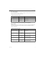
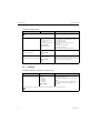
3.1
Sensor identification and damping
The following functions are available for every input. The description below is always the
same. However, any settings you make always individually affect the input selected.
Path: Menu/Setup/Inputs
Function
Options
Info
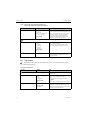
Sensor type
Options
• None
• Oxygen (amp.)
• Oxygen (opt.)
• pH Glass
• pH ISFET
• Cond c
• Cond i
• ORP
• Turbidity
• Nitrate
The function is only available if you have not
connected a sensor to the input in question.
You can select a sensor from the list and configure
the settings for the sensor type without connecting
the sensor.
Factory setting
None
<Parameter>
depending on which sensor has
been selected
If no sensor is connected:
The selected sensor type is displayed
If a sensor is connected:
The user enters the menu directly
If you are configuring the settings for an input without a sensor being connected, all the subsequent functions
move down one hierarchical level.
Channel
Options
• On
• Off
Factory setting
On
Sensor type
Order code
6
Read only
(Only available if a sensor is
connected)
On
The channel display is switched on in the
measuring mode
Off
The channel is not displayed in the measuring
mode, regardless of whether a sensor is connected
or not.
Connected sensor type
Order code of the connected sensor
Endress+Hauser
Liquiline CM442
Inputs: pH/ORP
Path: Menu/Setup/Inputs
Function
Options
Info
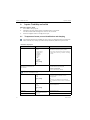
Main value
Options
• pH (only pH sensor)
• mV
• % (only ORP sensor)
Select the unit for the main measured value.
Factory setting
pH (pH sensor)
mV (ORP sensor)
Depending on the input:
Damping pH or
Damping ORP or
Damping Cond or
Damping turbidity or
Damping nitrate or
Damping DO
Damping temp.
0 to 60 s
Factory setting
0s
The damping causes a floating average curve of the
measured values over the time specified.
0 to 60 s
Factory setting
0s
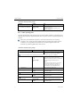
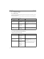
3.2
Temperature and medium compensation (only pH)
Path: Menu/Setup/Inputs/pH
Function
Options
Info
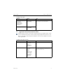
Temp. compensation
Options
• Off
• Automatic
• Manual
Decide how you want to compensate the medium
temperature:
• Automatically using the temperature sensor of
your sensor (ATC)
• Manually by entering the medium temperature
• Not at all
Factory setting
Automatic
This setting only refers to compensation during measurement. You enter the compensation for calibration in the
calibration settings.
Internal buffer
(only pH glass)
pH 0 to 14
Medium comp.
Options
• Off
• 2-point
• Table
Factory setting
pH 7.00
Only change the value if you are using a sensor
with an internal buffer other than pH 7.
Take a sample from the medium and determine its
pH value at different temperatures in the lab.
Decide whether you want to compensate using two
points or several points in a table.
Factory setting
Off
The dissociation of water changes with increasing temperature. The balance shifts towards the protons; the pH
value drops. You can balance out this effect with the "Medium compensation" function.
Endress+Hauser
7
Inputs: pH/ORP
Liquiline CM442
3.3
Main value and temperature format
Path: Menu/Setup/Inputs/pH or ORP
Function
Options
Info
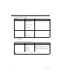
Main value format
(only pH)
Options
• #.#
• #.##
Specify the number of decimal places for displaying
the main measured value.
Factory setting
#.#
Temperature format
Options
• #.#
• #.##
Select how many decimal places should be used to
display the temperature.
Factory setting
#.#
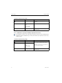
3.4
Cleaning
Path: Menu/Setup/Inputs/<Parameter> (depends on input)
Function
Options
Info
Cleaning
Options
• None
• Cleaning 1
• Cleaning 2
• Cleaning 3
• Cleaning 4
Select a cleaning program.
Factory setting
None
This program is executed if:
• A diagnostics message is present at the channel
and
• A cleaning process has been specified for this
message (--> "Inputs/Diag. settings/Diag.
behavior").
You define the cleaning programs in the "Setup/Additional functions/Cleaning" menu.
8
Endress+Hauser
Liquiline CM442
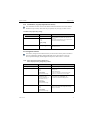
3.5
Inputs: pH/ORP
Calibration settings
3.5.1 Stability criteria
You define the permitted measured value fluctuation which must not be exceeded in a certain
timeframe during calibration.
If the permitted difference is exceeded, calibration is not permitted and is aborted automatically.
Path: Menu/Setup/Inputs/Calib. settings
Function
Options
Info
1 to 10 mV
Permitted measured value fluctuation during
calibration
Stability criteria
Delta mV
Factory setting
1 mV
Duration
10 to 60 s
Factory setting
20 s
Timeframe within which the permitted range for
measured value fluctuation should not be exceeded
3.5.2 Buffer recognition (only pH)
Automatic buffer recognition
To ensure a buffer is detected correctly, the measuring signal may deviate by a maximum of 30
mV from the value stored in the buffer table. This is approx. 0.5 pH at a temperature of 25°C.
If both buffers - 9.00 and 9.20 - were used, this would cause the signal intervals to overlap and
buffer recognition would not work. For this reason, the controller would recognize a buffer with
a pH of 9.00 as a pH of 9.20. --> Do not use the buffer with a pH of 9.00 for automatic buffer
recognition.
Path: Menu/Setup/Inputs/Calib. settings
Function
Options
Info
Temp. compensation
Options
• Off
• Automatic
• Manual
Decide how you want to compensate the buffer
temperature:
• Automatically using the temperature sensor of
your sensor (ATC)
• Manually by entering the buffer temperature
• Not at all
Factory setting
Automatic
Temperature
-50 to 250 °C (-58 to 482 °F)
Specify the buffer temperature.
Temp. compensation="Manual" Factory setting
25 °C (77 °F)
This setting only refers to compensation during calibration, not in measuring mode. You perform the
compensation in the measuring mode further down in the menu.
Endress+Hauser
9
Inputs: pH/ORP
Liquiline CM442
Path: Menu/Setup/Inputs/Calib. settings
Function
Options
Info
Buffer recognition
Options
• fixed
• Automatic (only pH glass)
• Manual
fixed
You choose values from a list. This list depends on
the setting for "Buffer manufacturer".
Factory setting
fixed
Automatic(only pH glass)
The controller recognizes the buffer automatically.
The recognition depends on the setting for "Buffer
manufacturer".
Manual
You enter any two buffer values. These must differ
in terms of their pH value.
Buffer manufacturer
Options
• Endress+Hauser
• Ingold/Mettler
• DIN 19266
• DIN 19267
• Merck/Riedel
• Hamilton
• Special buffer
Factory setting
Endress+Hauser
Temperature tables are stored internally in the unit
for the following pH values:
• Endress+Hauser
2.00 / 4.00 / 7.00 / (9.00) / 9.20 / 10.00 /
12.00
• Ingold/Mettler
2.00 / 4.01 / 7.00 / 9.21
• DIN 19266
1.68 / 4.01 / 6.86 / 9.18
• DIN 19267
1.09 / 4.65 / 6.79 / 9.23 / 12.75
• Merck/Riedel
2.00 / 4.01 / 6.98 / 8.95 / 12.00
• Hamilton
1.09 / 1.68 / 2.00 / 3.06 / 4.01 / 5.00 / 6.00
7.00 / 8.00 / 9.21 / 10.01 / 11.00 / 12.00
You have the possibility of defining two buffers of your own with the "Special buffer" option. For this purpose, two
tables are displayed in which you can enter value pH value/temperature value pairs.
Isotherm pnt.
pH 0 to 14
Factory setting
pH 7.00
10
Isotherm intersection
pH glass: Value is identical to the internal buffer.
Do not change the value.
pH-ISFET: The controller automatically accepts the
value saved at the factory.
Endress+Hauser
Liquiline CM442
Inputs: pH/ORP
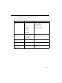
3.5.3 Calibration timer and calibration expiration date
You can specify the calibration interval for the sensor here.
Once the time configured elapses, the "Calibration timer" diagnostics message appears on the
display.
The timer is reset automatically if you recalibrate the sensor.
Path: Menu/Setup/Inputs/Calib. settings
Function
Options
Info
Calibration timer
Options
• Off
• On
Switches the function on or off
Factory setting
Off
Calibration timer
1 to 10000 h
Calibration timer="On"
Factory setting
1000 h
Calib. expiration date
Options
• Off
• On
Factory setting
Off
Specify the time after which the timer should have
timed out. Once this time has elapsed, the "Sensor
check" diagnostics message, along with the code
102, appears on the display.
The function checks whether the calibration of a
sensor is still valid.
Example: You install a precalibrated sensor. The
function checks how much time has elapsed since
the sensor was last calibrated. A diagnostics
message is displayed if the time since the last
calibration is longer than the predefined warning
and alarm limit.
Calib. expiration date
Warning limit
Alarm limit
Endress+Hauser
1 to 12 months
Diagnostics message: 105 "Sensor check"
Factory setting
11 months
Warning and alarm limits mutually affect each
other's possible ranges for adjustment.
1 to 12 months
Diagnostics message: 104 "Sensor check"
Factory setting
12 months
General rule:
Alarm limit > warning limit
11
Inputs: pH/ORP
3.6
Liquiline CM442
Diagnostics settings
This menu branch is used for specifying alarm and warning limits, and for defining whether and
how diagnostics tools should be used.
The associated diagnostics code is displayed for every setting.
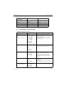
3.6.1 Sensor check system (only pH glass)
The sensor check system (SCS) monitors the high impedance of the pH glass.
An alarm is issued if a minimum impedance value is undershot or a maximum impedance is
exceeded.
• Glass breakage is the main reason for a drop in high impedance values.
• The reasons for increasing impedance values include:
– Dry sensor
– Worn pH glass membrane
Path: Menu/Setup/Inputs/Diag. settings
Function
Options
Info
Glass impedance (SCS)
0 to 10000 MΩ
Specify your limit values for monitoring the
impedance of the pH glass.
Function
Options
• On
• Off
On
SCS operates with the following settings for the
warning and alarm limits.
Off
SCS is switched off.
Factory setting
On
12
Upper alarm limit
Factory setting
2000 MΩ
Diagnostics code and associated message text:
124 "Sensor glass"
Upper warning limit
Factory setting
1600 MΩ
Diagnostics code and associated message text:
125 "Sensor glass"
Lower warning limit
Factory setting
1 MΩ
Diagnostics code and associated message text:
123 "Sensor glass"
Lower alarm limit
Factory setting
0 MΩ
Diagnostics code and associated message text:
122 "Sensor glass"
Endress+Hauser
Liquiline CM442
Inputs: pH/ORP
3.6.2 Slope (only pH)
The slope characterizes the sensor condition. The bigger the deviation from the ideal value (59
mV/pH) the poorer the condition of the sensor.
Path: Menu/Setup/Inputs/Diag. settings
Function
Options
Info
Slope
5.00 to 99.00 mV/pH
Specify your limit values for slope monitoring.
Warning limit
Factory setting
55.00 mV/pH
Associated diagnostics code and message text:
509 "Sensor calib."
Alarm limit
Factory setting
53.00 mV/pH
Associated diagnostics code and message text:
508 "Sensor calib."
3.6.3 Zero point (only pH glass) or Operating point (only pH-ISFET)
pH glass sensors
The zero point characterizes the condition of the sensor reference. The bigger the deviation from
the ideal value (pH 7.00) the poorer the condition. This can be caused by KCl leaking or
reference contamination.
Path: Menu/Setup/Inputs/Diag. settings
Function
Zero point (pH glass)
Operating point (pH ISFET)
Options
Info
pH glass
-2.00 to 16.00
Specify your limit values for zero point or operating
point monitoring.
pH ISFET
-950 mV to 950 mV
Upper alarm limit
Factory setting
pH 9.00 / 400 mV
Associated diagnostics code and message text:
504 "Sensor calib." (pH glass)
514 "Sensor calib." (pH ISFET)
Upper warning limit
Factory setting
pH 8.00 / 300 mV
Associated diagnostics code and message text:
505 "Sensor calib." (pH glass)
515 "Sensor calib." (pH ISFET)
Lower warning limit
Factory setting
pH 6.00 / -300 mV
Associated diagnostics code and message text:
507 "Sensor calib." (pH glass)
517 "Sensor calib." (pH ISFET)
Lower alarm limit
Factory setting
pH 5.00 / -400 mV
Associated diagnostics code and message text:
506 "Sensor calib." (pH glass)
516 "Sensor calib." (pH ISFET)
Endress+Hauser
13
Inputs: pH/ORP
Liquiline CM442
3.6.4 Sensor condition check (only pH glass)
Sensor condition check (SCC) monitors the electrode status and the degree of electrode aging.
The electrode status is updated after every calibration.
The main reasons for a deteriorating electrode status are:
• Glass membrane blocked or dry
• Diaphragm (reference) blocked
Remedial action
1. Clean or regenerate the sensor.
2. Replace the sensor if this does not have the desired effect.
Path: Menu/Setup/Inputs/Diag. settings
Function
Options
Sensor Condition Check
Function
Info
The function can only be switched on or off. It uses
internal limit values
Options
• On
• Off
Diagnostics code and associated message text:
127 "SCC sufficient"
126 "SCC bad"
Factory setting
On
3.6.5 ORP-Meas value (only ORP)
You can specify limit values in order to monitor your process. A diagnostics message is displayed
if the limits are exceeded or undershot.
Path: Menu/Setup/Inputs/Diag. settings
Function
Options
ORP-Meas value
14
Info
Specify your limit values for monitoring the
measured value.
Upper alarm limit
Factory setting
1000 mV
Diagnostics code and associated message text:
842 "Process value"
Upper warning limit
Factory setting
900 mV
Diagnostics code and associated message text:
942 "Process value"
Lower warning limit
Factory setting
-900 mV
Diagnostics code and associated message text:
943 "Process value"
Lower alarm limit
Factory setting
-1000 mV
Diagnostics code and associated message text:
843 "Process value"
Endress+Hauser
Liquiline CM442
Inputs: pH/ORP
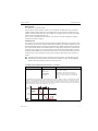
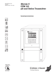
3.6.6 Process check system
The process check system (PCS) checks the measuring signal for stagnation. An alarm is
triggered if the measuring signal does not change over a certain period (several measured values).
y
y
t
yT
yT
tD
tA
a0013107
a0013106
Fig. 7: Normal measuring signal, no alarm
Fig. 8: Stagnating signal, alarm is triggered
y
yT
tD
tA
Measuring signal
Set value for "Tolerancewidth"
t
Set value for "Duration"
Time when the alarm is triggered
The main causes of stagnating measured values are:
• Contaminated sensor, or sensor in air
• Sensor failure
• Process error (e.g. through control system)
Remedial action
1. Clean the sensor.
2. Check the measuring chain.
3. Switch off the controller and switch it back on again.
Path: Menu/Setup/Inputs/Diag. settings
Function
Options
Process Check System
Function
Info
Diagnostics code and associated message text:
904 "Process check"
Options
• On
• Off
Factory setting
On
Duration
1 to 240 min
Factory setting
60 min
Endress+Hauser
The measured value must change during this time.
Otherwise the error message is triggered.
15
Inputs: pH/ORP
Liquiline CM442
Path: Menu/Setup/Inputs/Diag. settings
Function
Options
Info
Tolerancewidth
0.01 to 20 %
not available with pH/Redox
Factory setting
0.05 %
Interval around the measuring signal (raw value)
for detecting stagnation.
Measured values within the set interval are
regarded as stagnating.
3.6.7 Limits operating hours
The total operating time of the sensor and its use under extreme conditions is monitored. If the
operating time exceeds the defined threshold values, the device issues a corresponding warning
or alarm.
Each sensor has a limited life expectancy which heavily depends on the operating
conditions. If you specify warning and alarm limits for operating times under extreme
conditions, you can guarantee the operation of your measuring point without any
downtime by performing maintenance tasks in time.
Path: Menu/Setup/Inputs/Diag. settings
Function
Options
Limits operating hours
Info
Specify your limit values for monitoring the number
of operating hours under extreme conditions.
The range of adjustment for the operating hours alarm and warning limits is generally 1 to 50000 h.
Function
Options
• On
• Off
Factory setting
On
Operating time
Warning limit
On
The operation of the sensor under extreme
conditions is monitored, recorded in the sensor and
diagnostics messages are displayed on the
controller.
Off
No diagnostics messages. However, the time the
sensor operates under extreme conditions is
recorded in the sensor and can be read in the
sensor information in the diagnostics menu.
Total operating time of the sensor
Factory setting
10000 h
Diagnostics code and associated message text:
199 "Operating time"
Factory setting
10000 h
Diagnostics code and associated message text:
193 "Operating time"
Factory setting
10000 h
Diagnostics code and associated message text:
194 "Operating time"
Operation > 80°C
Warning limit
Operation > 100°C
Warning limit
16
Endress+Hauser
Liquiline CM442
Inputs: pH/ORP
Path: Menu/Setup/Inputs/Diag. settings
Function
Options
Operation < -300 mV
Warning limit
Factory setting
10000 h
Operation > 300 mV
Warning limit
Info
only pH
Diagnostics code and associated message text:
180 "Operating time"
only pH
Factory setting
10000 h
Diagnostics code and associated message text:
179 "Operating time"
3.6.8 Delta slope (only pH)
The device determines the difference in slope between the last calibration and the penultimate
calibration, and issues a warning or an alarm depending on the setting configured. The difference
is an indicator for the condition of the sensor. The greater the change, the greater the wear
experienced by the pH-sensitive glass membrane as a result of chemical corrosion or abrasion.
Path: Menu/Setup/Inputs/Diag. settings
Function
Options
Info
Delta slope
0.10 to 10.00
Specify your limit values for monitoring the slope
differential.
Function
Options
• On
• Off
Factory setting
Off
Warning limit
Factory setting
5.00 mV/pH
Diagnostics code and associated message text:
518 "Sensor calib."
Alarm limit
Factory setting
6.00 mV/pH
Diagnostics code and associated message text:
145 "Delta slope al"
3.6.9 Delta zeropoint (only pH glass) or Delta operating point (only pH ISFET)
The device determines the difference between the last calibration and the penultimate
calibration, and issues a warning or an alarm depending on the setting configured. The difference
is an indicator for the condition of the sensor. The following applies to pH glass electrodes: The
greater the change, the greater the wear experienced by the reference as a result of
contaminating ions or KCl leaks.
Endress+Hauser
17
Inputs: pH/ORP
Liquiline CM442
Path: Menu/Setup/Inputs/Diag. settings
Function
Delta zeropoint (pH glass)
Delta operating point (pH
ISFET)
Function
Options
Info
pH glass
pH 0.00 to 2.00
Specify your limit values for monitoring the zero
point or operating point differential.
pH ISFET
0 to 950 mV
Options
• On
• Off
Factory setting
Off
Warning limit
Factory setting
pH 0.50 / 25 mV
Diagnostics code and associated message text:
520 "Sensor calib." (pH glass)
522 "Sensor calib." (pH ISFET)
Alarm limit
Factory setting
pH 1.00 / 50 mV
Diagnostics code and associated message text:
519 "Sensor calib." (pH glass)
521 "Sensor calib." (pH ISFET)
3.6.10 Sterilizations
The system counts the number of operating hours in which the sensor is exposed to a
temperature that is typical for a sterilization. This temperature depends on the sensor.
Path: Menu/Setup/Inputs/Diag. settings
Function
Options
Info
Sterilizations
0 to 99
Specify the limit values for the number of sensor
sterilizations.
Function
Options
• On
• Off
Factory setting
Off
Warning limit
Factory setting
30
Diagnostics code and associated message text:
108 "Sensor check"
3.6.11 Diagnostic behavior
This branch, along with the same functions, can be found in various parts of the menu.
The list of diagnostic messages displayed depends on the path selected. There are
device-specific messages, and messages that depend on what sensor is connected.
18
Endress+Hauser
Liquiline CM442
Paths:
Inputs: pH/ORP
Menu/Setup/General settings/Diagnostics or
Menu/Setup/Inputs/Diag. settings/Diag. behavior
Function
Options
List of diagnostic messages
Diagnostic message
Select the message to be changed.
Options
• On
• Off
Factory setting
Depends on the message
Error class
Info
Options
• Maintenance (M)
• Out of specification (S)
• Function check (C)
• Failure (F)
You can deactivate or reactivate a diagnostic
message here.
Deactivating means:
• No error message in the measuring mode
• No error current at the current output
The messages are divided into different error classes
in accordance with NAMUR NE 107.
--> BA445C "Maintenance&diagnostics"
Factory setting
Depends on the message
Error current
Options
• On
• Off
Decide whether an error current should be output
at the current output if the diagnostic message
display is activated.
Factory setting
Depends on the message
Diag. output
Options
• None
• Alarm relay
• Relay 1 to n (depends on
the device version)
Factory setting
None
You can use this function to select an output to
which the diagnostic message should be assigned.
You first have to configure a relay output before
being able to assign the message to an output
(Menu/Setup/Outputs, assign "Diagnostics"
function and set Operating mode to "Normal").
--> BA450C "Operation&configuration"
One alarm relay is always available, regardless of the device version. Other relays are optional.
Cleaning program
Options
• None
• Cleaning 1
• Cleaning 2
• Cleaning 3
• Cleaning 4
Decide whether the diagnostic message should
trigger a cleaning program.
You can define the cleaning programs under:
Menu/Setup/Additional functions/Cleaning.
Factory setting
None
Info
Endress+Hauser
Read only
Here you can find more information on the
diagnostic message and instructions on how to
resolve the problem.
19
Inputs: pH/ORP
3.7
Liquiline CM442
Tag control
"Tag" stands for the name of a measuring point, and is used in many areas of process
measuring technology.
Path: Menu/Setup/Inputs
Function
Options
Tag control
Operating mode
Options
• Off
• Tag
• Tag group
Factory setting
Off
Tag group
Customized text
Factory setting
EH_CM44_
3.8
Info
Additional information on the display: tag control
currently used
Off
No tag control, all sensors are accepted.
Tag
Only sensors with the same tag are accepted.
Tag group
Only sensors in the same tag group are accepted.
Enter the tag name. The controller checks every
sensor to be connected as to whether this sensor
belongs to the measuring point, and only accepts
the sensors that have the same tag.
Sensor input factory setting
Here you can restore the factory settings for the sensor input. For this purpose, simply press the
navigator button and select "OK" when the prompt for the device software appears.
Only the factory settings for this particular input are restored. All other settings remain
unchanged.
20
Endress+Hauser
Liquiline CM442
Inputs: Conductivity
4
Inputs: Conductivity
Enter the "Inputs" menu
1. Select: Menu/Setup/Inputs.
2. Navigate to an input channel to which a conductivity sensor is connected.
3. Press the navigator button to configure the input.
4.1
Temperature format, sensor identification and damping
The following functions are available for every input. The description below is always the
same. However, any settings you make always individually affect the input selected.
Path: Menu/Setup/Inputs
Function
Options
Info
Sensor type
Options
• None
• Oxygen (amp.)
• Oxygen (opt.)
• pH Glass
• pH ISFET
• Cond c
• Cond i
• ORP
• Turbidity
• Nitrate
The function is only available if you have not
connected a sensor to the input in question.
You can select a sensor from the list and configure
the settings for the sensor type without connecting
the sensor.
Factory setting
None
<Parameter>
depending on which sensor has
been selected
If no sensor is connected:
The selected sensor type is displayed
If a sensor is connected:
The user enters the menu directly
If you are configuring the settings for an input without a sensor being connected, all the subsequent functions
move down one hierarchical level.
Channel
Options
• On
• Off
Factory setting
On
Temperature format
Options
• #.#
• #.##
On
The channel display is switched on in the
measuring mode
Off
The channel is not displayed in the measuring
mode, regardless of whether a sensor is connected
or not.
Select how many decimal places should be used to
display the temperature.
Factory setting
#.#
Sensor type
Order code
Endress+Hauser
Read only
(Only available if a sensor is
connected)
Connected sensor type
Order code of the connected sensor
21
Inputs: Conductivity
Liquiline CM442
Path: Menu/Setup/Inputs
Function
Options
Info
Depending on the input:
Damping pH or
Damping ORP or
Damping Cond or
Damping turbidity or
Damping nitrate or
Damping DO
0 to 60 s
The damping causes a floating average curve of the
measured values over the time specified.
Damping temp.
0 to 60 s
Factory setting
0s
Factory setting
0s
4.2
Operating mode and cell constant
Path: Menu/Setup/Inputs/Conductivity
Function
Options
Info
Operating mode
Options
• Conductivity
• Resistance
(only Cond c)
• Concentration
(only Cond i)
Alternatively to the conductivity, you can also
measure the resistivity with a conductive
conductivity sensor.
Alternatively to the conductivity, you can
determine the concentration of the medium with
an inductive conductivity sensor.
Factory setting
Conductivity
Cell constant
22
Read only
(Only available if a sensor is
connected)
The cell constant of the connected sensor is
displayed (--> sensor certificate)
Endress+Hauser
Liquiline CM442
Inputs: Conductivity
4.3
Installation factor (only inductive sensors)
Path: Menu/Setup/Inputs/Conductivity
Function
Options
Info
Inst. factor
Read only
(Only available if a sensor is
connected)
Displays the current value. Only changes with a
calibration.
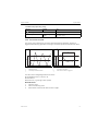
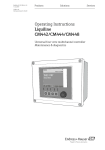
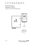
In confined installation conditions, the wall affects conductivity measurement in the liquid.
The installation factor compensates for this effect. The transmitter corrects the cell constant by
multiplying by the installation factor.
The size of the installation factor depends on the diameter and the conductivity of the pipe
nozzle, as well as the distance between the sensor and the wall.
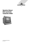
If there is a sufficient distance between the wall and the sensor (a > 15 mm (0.59"), from
DN 80), the installation factor f does not have to be taken into consideration (f = 1.00).
If distances from the wall are smaller, the installation factor is bigger for electrically insulating
pipes (f >1), and smaller for electrically conductive pipes (f < 1).
It can be measured using calibration solutions, or a close approximation determined from the
following diagram.
f
1.40
2
1.20
1.00
1
0.80
0
5
10
15
20
0.20
0.39
0.59
0.79
25
a [mm]
0.98 a [inch]
a0005441
Fig. 9: Relation between the installation factor f and the wall distance
1
2
Endress+Hauser
Electrically conductive pipe wall
Electrically insulating pipe wall
23
Inputs: Conductivity
4.4
Liquiline CM442
Concentration table (only inductive sensors)
Path: Menu/Setup/Inputs/Conductivity
Function
Options
Info
Conc. Table
(Operating
mode=Concentration)
Options
• NaOH 0..15%
• NaOH 18..50%
• HCl
• HNO3
• H2SO4 0..30%
• H2SO4 32..84%
• H3PO4
• User table 1
• User table 2
• User table 3
• User table 4
Concentration tables saved at the factory:
NaOH: 0 to 15%, 0 to 100 °C
NaOH: 18 to 50%, 0 to 100 °C
HCl: 0 to 20%, 0 to 80 °C
HNO3: 0 to 25%, 0 to 90 °C
H2SO4: 0 to 30%, 0 to 100 °C
H2SO4: 32 to 84%, 0 to 100 °C
H3PO4: 0 to 15%, 0 to 90 °C
Factory setting
NaOH 0..15%
Temp. comp. mode
(Operating
mode=Concentration)
Options
• with temp. comp
• without temp. comp
Only select "without temp. comp" in very small
temperature ranges.
In all other cases, select "with temp. comp".
Factory setting
with temp. comp
24
Table name
(Conc. Table=one of the user
tables)
Customized text, 16
characters
Assign a meaningful name to the selected table.
Edit table
(Conc. Table=one of the user
tables)
3-column table
Assign conductivity and concentration value pairs
for a specific temperature.
Conc. unit
(Operating
mode=Concentration)
Read only
%
This is for information purposes only. No options
are available.
Endress+Hauser
Liquiline CM442
Inputs: Conductivity
Example of a concentration table:
Conductivity
(uncompensated)
Concentration
Temperature
1.000 mS/cm
0.000 mg/l
0.00 °C
2.000 mS/cm
0.000 mg/l
100.00 °C
100.0 mS/cm
3.000 mg/l
0.00 °C
300.0 mS/cm
3.000 mg/l
100.00 °C
4.5
Main measured value and unit
Path: Menu/Setup/Inputs/Conductivity
Function
Options
Info
Cond. unit
(Operating mode=Conductivity)
Options
Conductivity/resistance
• Auto / Auto
• μS/cm / MΩm
• mS/cm / MΩcm
• S/cm / kΩcm
• μS/m / kΩm
• mS/m / Ωm
• S/m / Ωcm
The picklist depends on the operating mode.
You can either choose from units for conductivity
or units for resistivity.
Since there are no options for concentration
measurement, this function is not displayed for
such measurements.
Unit
(Operating mode=Resistance)
Factory setting
Auto / Auto
Main value format
Options
• Auto
• #
• #.#
• #.##
• #.###
Specify the number of decimal places.
"Auto" means: the number of digits is automatically
set in dependence of the measured value.
Factory setting
#.###
Alpha ref. temp.
Temp. source
-5.0 to 100.0 °C
(23.0 to 212.0 °F)
Reference temperature for calculating the
temperature-compensated conductivity
Factory setting
25.0 °C (77.0 °F)
The alpha coefficients and alpha reference
temperatures of Endress+Hauser calibration
solutions can be found in the documentation
enclosed.
Options
• Sensor
• Manual
Decide how you want to compensate the medium
temperature:
• Automatically using the temperature sensor of
your sensor
• Manually by entering the medium temperature
Factory setting
Sensor
Medium temperature
(Temp. source=Manual)
-50.0 to 250.0 °C
(-58.0 to 482.0 °F)
Enter the temperature of your medium.
Factory setting
25.0 °C (77 °F)
Endress+Hauser
25
Inputs: Conductivity
4.6
Liquiline CM442
Temperature compensation
Temperature coefficient α = change in the conductivity per degree of temperature change:
κ(T) = κ(T0)(1 + α(T - T0))
κ(T) ... conductivity at process temperature T
κ(T0) ... conductivity at reference temperature T0
The temperature coefficient depends both on the chemical composition of the solution and the
temperature itself.
Path: Menu/Setup/Inputs/Conductivity
Function
Options
Info
Compensation
(Operating mode=Conductivity)
Options
• None
• Linear
• NaCl (IEC 746-3)
• Water ISO7888
• UPW NaCl
• UPW HCl
• User table 1
• User table 2
• User table 3
• User table 4
Various methods are available to compensate for
the temperature dependency.
Depending on your process, decide which type of
compensation you want to use.
Alternatively, you can also select "None" and thus
measure uncompensated conductivity.
Factory setting
Linear
Linear temperature compensation
The change between two temperature points is taken to be constant, i.e. α = const. The value for alpha is stored in the
sensor and is recalculated for each calibration. You already specified the related reference temperature in this menu.
26
Endress+Hauser
Liquiline CM442
Inputs: Conductivity
Path: Menu/Setup/Inputs/Conductivity
Function
Options
Info
a [%/K]
NaCl compensation
In the case of NaCl compensation (as per IEC 60746), a fixed non-linear curve specifying the relationship between the
temperature coefficient and temperature is saved in the device. This curve applies to low concentrations of up to approx.
5 % NaCl.
2.7
2.5
2.3
2.1
0
48
96
144
T [°C]
Compensation for natural water
A non-linear in accordance with ISO 7888 is saved in the device for temperature compensation in natural water.
Ultrapure water compensation (for conductive sensors)
Algorithms for pure and ultrapure water are stored in the device. These algorithms take the dissociation of the water and
its temperature dependency into account. They are used for conductivity values up to approx. 100 μS/cm.
• UPW NaCl: Optimized for pH-neutral contamination.
• UPW HCl: Optimized for measuring the acid conductivity downstream of a cation exchanger. Also suitable for
ammonia (NH3) and caustic soda (NaOH).
User-defined tables
You can save a function that takes the properties of your specific process into account. To do so, determine the value
pairs made up of the temperature T and conductivity κ with:
• κ(Τ0) for the reference temperature T0
• κ(T) for the temperatures that occur in the process
Use the following formula to calculate the α values for the temperatures that are relevant in your process:
a = 100% . k(T) - k(T0) ; T ¹ T0
T - T0
k(T0)
Temp. comp. mode
(Operating mode=Conductivity)
Options
• Conductivity
• Coeff. Alpha
Factory setting
Conductivity
Endress+Hauser
Conductivity
You specify the temperature, conductivity and
uncompensated conductivity. Recommended for
large measuring ranges and small measured values.
Coeff. Alpha
As the value pairs, you specify an alpha value and
the related temperature.
27
Inputs: Conductivity
Liquiline CM442
Path: Menu/Setup/Inputs/Conductivity
Function
Options
Info
Table name
(Compensation=one of the user
tables)
Customized text, 16
characters
Assign a meaningful name to the selected table.
Edit table
(Compensation=one of the user
tables)
• Temperature
• Conductivity
• Temperature comp. cond.
Maximum number of rows: 25
The type of table depends on the option under
"Temp. comp. mode".
or
• Temperature
• Coefficient alpha
4.7
Cleaning
Path: Menu/Setup/Inputs/<Parameter> (depends on input)
Function
Options
Info
Cleaning
Options
• None
• Cleaning 1
• Cleaning 2
• Cleaning 3
• Cleaning 4
Select a cleaning program.
Factory setting
None
This program is executed if:
• A diagnostics message is present at the channel
and
• A cleaning process has been specified for this
message (--> "Inputs/Diag. settings/Diag.
behavior").
You define the cleaning programs in the "Setup/Additional functions/Cleaning" menu.
28
Endress+Hauser
Liquiline CM442
Inputs: Conductivity
4.8
Diagnostics settings
This menu branch is used for specifying alarm and warning limits, and for defining whether and
how diagnostics tools should be used.
The associated diagnostics code is displayed for every setting.
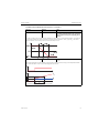
4.8.1 Process check system
The process check system (PCS) checks the measuring signal for stagnation. An alarm is
triggered if the measuring signal does not change over a certain period (several measured values).
y
y
t
yT
yT
tD
tA
a0013107
a0013106
Fig. 10: Normal measuring signal, no alarm
Fig. 11: Stagnating signal, alarm is triggered
y
yT
tD
tA
Measuring signal
Set value for "Tolerancewidth"
t
Set value for "Duration"
Time when the alarm is triggered
The main causes of stagnating measured values are:
• Contaminated sensor, or sensor in air
• Sensor failure
• Process error (e.g. through control system)
Remedial action
1. Clean the sensor.
2. Check the measuring chain.
3. Switch off the controller and switch it back on again.
Path: Menu/Setup/Inputs/Diag. settings
Function
Options
Process Check System
Function
Info
Diagnostics code and associated message text:
904 "Process check"
Options
• On
• Off
Factory setting
On
Endress+Hauser
29
Inputs: Conductivity
Liquiline CM442
Path: Menu/Setup/Inputs/Diag. settings
Function
Duration
Options
Info
1 to 240 min
The measured value must change during this time.
Otherwise the error message is triggered.
Factory setting
60 min
Tolerancewidth
0.01 to 20 %
not available with pH/Redox
Factory setting
0.05 %
Interval around the measuring signal (raw value)
for detecting stagnation.
Measured values within the set interval are
regarded as stagnating.
4.8.2 Limits operating hours
The total operating time of the sensor and its use under extreme conditions is monitored. If the
operating time exceeds the defined threshold values, the device issues a corresponding warning
or alarm.
Each sensor has a limited life expectancy which heavily depends on the operating
conditions. If you specify warning and alarm limits for operating times under extreme
conditions, you can guarantee the operation of your measuring point without any
downtime by performing maintenance tasks in time.
Path: Menu/Setup/Inputs/Diag. settings
Function
Options
Info
Limits operating hours
The range of adjustment for the operating hours alarm and warning limits is generally 1 to 50000 h.
Function
Options
• On
• Off
Factory setting
Off
Operating time
Warning limit
On
The operation of the sensor under extreme
conditions is monitored, recorded in the sensor and
diagnostics messages are displayed on the
controller.
Off
No diagnostics messages. However, the time the
sensor operates under extreme conditions is
recorded in the sensor and can be read in the
sensor information in the diagnostics menu.
Total operating time of the sensor
Factory setting
10000 h
Diagnostics code and associated message text:
199 "Operating time"
Factory setting
10000 h
Diagnostics code and associated message text:
193 "Operating time"
Operation > 80°C
Warning limit
30
Endress+Hauser
Liquiline CM442
Inputs: Conductivity
Path: Menu/Setup/Inputs/Diag. settings
Function
Options
Operation > 120°C
Warning limit
Factory setting
10000 h
Operation > 125°C
Warning limit
Factory setting
10000 h
Factory setting
10000 h
Factory setting
10000 h
Diagnostics code and associated message text:
198 "Operating time"
Only conductive sensors
Factory setting
10000 h
Operation < 5°C
Warning limit
Diagnostics code and associated message text:
197 "Operating time"
Only inductive sensors
Operation > 80°C <
100nS/cm
Warning limit
Diagnostics code and associated message text:
196 "Operating time"
Only conductive sensors
Operation > 150°C
Warning limit
Diagnostics code and associated message text:
195 "Operating time"
Only inductive sensors
Operation > 140°C
Warning limit
Info
Only conductive sensors
Diagnostics code and associated message text:
187 "Operating time"
Only inductive sensors
Factory setting
10000 h
Diagnostics code and associated message text:
188 "Operating time"
4.8.3 Sterilizations
The system counts the number of operating hours in which the sensor is exposed to a
temperature that is typical for a sterilization. This temperature depends on the sensor.
Path: Menu/Setup/Inputs/Diag. settings
Function
Options
Info
Sterilizations
0 to 99
Specify the limit values for the number of sensor
sterilizations.
Function
Options
• On
• Off
Factory setting
Off
Warning limit
Endress+Hauser
Factory setting
30
Diagnostics code and associated message text:
108 "Sensor check"
31
Inputs: Conductivity
Liquiline CM442
4.8.4 Diagnostic behavior
This branch, along with the same functions, can be found in various parts of the menu.
The list of diagnostic messages displayed depends on the path selected. There are
device-specific messages, and messages that depend on what sensor is connected.
Paths:
Menu/Setup/General settings/Diagnostics or
Menu/Setup/Inputs/Diag. settings/Diag. behavior
Function
Options
Info
Options
• On
• Off
You can deactivate or reactivate a diagnostic
message here.
List of diagnostic messages
Diagnostic message
Select the message to be changed.
Factory setting
Depends on the message
Error class
Options
• Maintenance (M)
• Out of specification (S)
• Function check (C)
• Failure (F)
Deactivating means:
• No error message in the measuring mode
• No error current at the current output
The messages are divided into different error classes
in accordance with NAMUR NE 107.
--> BA445C "Maintenance&diagnostics"
Factory setting
Depends on the message
Error current
Options
• On
• Off
Decide whether an error current should be output
at the current output if the diagnostic message
display is activated.
Factory setting
Depends on the message
Diag. output
Options
• None
• Alarm relay
• Relay 1 to n (depends on
the device version)
Factory setting
None
You can use this function to select an output to
which the diagnostic message should be assigned.
You first have to configure a relay output before
being able to assign the message to an output
(Menu/Setup/Outputs, assign "Diagnostics"
function and set Operating mode to "Normal").
--> BA450C "Operation&configuration"
One alarm relay is always available, regardless of the device version. Other relays are optional.
Cleaning program
Options
• None
• Cleaning 1
• Cleaning 2
• Cleaning 3
• Cleaning 4
Decide whether the diagnostic message should
trigger a cleaning program.
You can define the cleaning programs under:
Menu/Setup/Additional functions/Cleaning.
Factory setting
None
Info
32
Read only
Here you can find more information on the
diagnostic message and instructions on how to
resolve the problem.
Endress+Hauser
Liquiline CM442
Inputs: Conductivity
4.8.5 Polarization detection (only conductive sensors)
As a result of flow through the electrolyte/electrode interface, reactions take place here which
result in additional voltage. These polarization effects limit the measuring range of conductive
sensors. Sensor-specific compensation increases the level of accuracy at the measuring range
limits.
The controller recognizes the Memosens sensor and automatically uses suitable
compensation. You can view the measuring range limits of the sensor under
Diagnostics/Sensor information/Sensor specifications.
Path: Menu/Setup/Inputs/Conductivity/Polarisation
Function
Options
Info
Polarisation
Options
• On
• Off
Diagnostics code and associated message text:
168 "Sensor check"
Factory setting
Off
4.9
Tag control
"Tag" stands for the name of a measuring point, and is used in many areas of process
measuring technology.
Path: Menu/Setup/Inputs
Function
Options
Tag control
Operating mode
Additional information on the display: tag control
currently used
Options
• Off
• Tag
• Tag group
Factory setting
Off
Tag group
Customized text
Factory setting
EH_CM44_
Endress+Hauser
Info
Off
No tag control, all sensors are accepted.
Tag
Only sensors with the same tag are accepted.
Tag group
Only sensors in the same tag group are accepted.
Enter the tag name. The controller checks every
sensor to be connected as to whether this sensor
belongs to the measuring point, and only accepts
the sensors that have the same tag.
33
Inputs: Conductivity
Liquiline CM442
4.10 Sensor input factory setting
Here you can restore the factory settings for the sensor input. For this purpose, simply press the
navigator button and select "OK" when the prompt for the device software appears.
Only the factory settings for this particular input are restored. All other settings remain
unchanged.
4.11 Sensor factory setting (CLS50D only)
Here you can restore the sensor factory settings. For this purpose, simply press the navigator
button and select "OK" when the prompt for the device software appears.
Only the factory settings for the sensor are restored. The settings for the input remain
unchanged.
34
Endress+Hauser
Liquiline CM442
Inputs: Oxygen
5
Inputs: Oxygen
Enter the "Inputs" menu
1. Select: Menu/Setup/Inputs.
2. Navigate to an input channel to which an oxygen sensor is connected.
3. Press the navigator button to configure the input.
5.1
Temperature format, sensor identification and damping
The following functions are available for every input. The description below is always the
same. However, any settings you make always individually affect the input selected.
Path: Menu/Setup/Inputs
Function
Options
Info
Sensor type
Options
• None
• Oxygen (amp.)
• Oxygen (opt.)
• pH Glass
• pH ISFET
• Cond c
• Cond i
• ORP
• Turbidity
• Nitrate
The function is only available if you have not
connected a sensor to the input in question.
You can select a sensor from the list and configure
the settings for the sensor type without connecting
the sensor.
Factory setting
None
<Parameter>
depending on which sensor has
been selected
If no sensor is connected:
The selected sensor type is displayed
If a sensor is connected:
The user enters the menu directly
If you are configuring the settings for an input without a sensor being connected, all the subsequent functions
move down one hierarchical level.
Channel
Options
• On
• Off
Factory setting
On
Temperature format
Options
• #.#
• #.##
On
The channel display is switched on in the
measuring mode
Off
The channel is not displayed in the measuring
mode, regardless of whether a sensor is connected
or not.
Select how many decimal places should be used to
display the temperature.
Factory setting
#.#
Sensor type
Order code
Endress+Hauser
Read only
(Only available if a sensor is
connected)
Connected sensor type
Order code of the connected sensor
35
Inputs: Oxygen
Liquiline CM442
Path: Menu/Setup/Inputs
Function
Options
Info
Depending on the input:
Damping pH or
Damping ORP or
Damping Cond or
Damping turbidity or
Damping nitrateor
Damping DO
0 to 60 s
The damping causes a floating average curve of the
measured values over the time specified.
Damping temp.
0 to 60 s
Factory setting
0s
Factory setting
0s
5.2
Main value
Path: Menu/Setup/Inputs/DO
Function
Options
Main value
Options
• Concentration liquid
• Concentration gaseous
• Saturation
• Partial pressure
• Raw value nA
Info
Factory setting
Concentration liquid
Unit
Main value="Concentration
liquid" or "Concentration
gaseous"
Options
(Main value="Concentration
liquid")
• mg/l
• μg/l
• ppm
• ppb
Options
(Main value="Concentration
gaseous")
• %Vol
• ppmVol (Main
value="Concentration
gaseous"
Factory setting
mg/l
%Vol
36
Endress+Hauser
Liquiline CM442
5.3
Inputs: Oxygen
Medium compensation (in the process)
Path: Menu/Setup/Inputs/DO
Function
Options
Medium pressure
Options
• Process pressure
• Air pressure
Info
Factory setting
Air pressure
Altitude
-300 to 4000 m
Medium pressure="Air
pressure"
Factory setting
0m
Air pressure or Medium pressure Medium pressure="Air
pressure"
500 to 1200 hPa
Enter the altitude or the average air pressure
(mutually dependent values).
If you specify the altitude, the average air pressure
is calculated from the barometric altitude formula
and vice versa.
If you are compensating using the process pressure,
enter the pressure in your process here. The
pressure is then independent of the altitude.
Medium pressure="Process
pressure"
500 to 9999 hPa
Factory setting
1013 hPa
Salinity
0 to 100 g/kg
Factory setting
0 g/kg
5.4
The influence of salt content on oxygen
measurement is compensated with this function.
Example: sea water measurement as per
Copenhagen Standard (30 g/kg).
Polarization voltage (only amperometric sensors)
A polarization voltage between the anode and the cathode is applied at the cathode of the
amperometric sensor. This causes the oxygen dissolved in the electrolyte to be reduced
selectively at the cathode. Given a constant polarization voltage, the electrical current resulting
from the cathode and anode reaction is proportional to the concentration of oxygen.
You can configure the polarization voltage depending on the process.
If the polarization voltage is switched off, you can achieve a longer sensor service life under
extreme conditions.
Endress+Hauser
37
Inputs: Oxygen
Liquiline CM442
Path: Menu/Setup/Inputs/DO
Function
Options
Sensor pol.voltage
Mode
Options
• Off
• Internal sensor value
• Setting up
• Off at def. temperature
Factory setting
Internal sensor value
Sensor pol.voltage
0 to 750 mV
Mode="Setting up"
Factory setting
650 mV
Temperature
50.0 to 140.0 °C
122.0 to 284.0 °F
Mode="Off at def. temperature"
Factory setting
80 °C
176 °F
5.5
Info
Polarization voltage of the sensor (standard: 650
mV)
• Off
No polarization, e.g. if temperatures are at a
constantly high level
• Internal sensor value
Polarization voltage saved in the sensor
• Setting up
Other polarization voltage
• Off at def. temperature
No polarization above this temperature
Enter the desired polarization voltage.
Specify the temperature as of which the sensor
should no longer be polarized (extreme operating
conditions). The polarization voltage saved in the
sensor is used up to this temperature.
Cleaning
Path: Menu/Setup/Inputs/<Parameter> (depends on input)
Function
Options
Info
Cleaning
Options
• None
• Cleaning 1
• Cleaning 2
• Cleaning 3
• Cleaning 4
Select a cleaning program.
Factory setting
None
This program is executed if:
• A diagnostics message is present at the channel
and
• A cleaning process has been specified for this
message (--> "Inputs/Diag. settings/Diag.
behavior").
You define the cleaning programs in the "Setup/Additional functions/Cleaning" menu.
38
Endress+Hauser
Liquiline CM442
5.6
Inputs: Oxygen
Calibration settings
5.6.1 Stability criteria
You define the permitted measured value fluctuation which must not be exceeded in a certain
timeframe during calibration.
If the permitted difference is exceeded, calibration is not permitted and is aborted automatically.
Path: Menu/Setup/Inputs/Calib. settings
Function
Options
Info
0.1 to 2.0 %
Permitted measured value fluctuation during
calibration. Referenced to the raw value in nA in
the case of amperometric sensors, and referenced to
the partial pressure in the case of optical sensors.
Stability criteria
Delta signal
Factory setting
0.2 %
Delta temperature
0.10 to 2.00 °C
0.18 to 3.60 °F
Permitted temperature fluctuation during
calibration
Factory setting
0.50 °C
0.90 °F
Duration
10 to 60 s
Factory setting
20 s
Timeframe within which the permitted range for
measured value fluctuation should not be exceeded
5.6.2 Medium compensation (during calibration)
Path: Menu/Setup/Inputs/DO/Calib. settings
Function
Options
Medium pressure
Options
• Process pressure
• Air pressure
Info
Factory setting
Air pressure
Altitude
-300 to 4000 m
Medium pressure="Air
pressure"
Factory setting
0m
Air pressure or Medium pressure Medium pressure="Air
pressure"
500 to 1200 hPa
Enter the altitude or the average air pressure
(mutually dependent values).
If you specify the altitude, the average air pressure
is calculated from the barometric altitude formula
and vice versa.
If you are compensating using the process pressure,
enter the pressure in your process here. The
pressure is then independent of the altitude.
Medium pressure="Process
pressure"
500 to 9999 hPa
Factory setting
1013 hPa
Endress+Hauser
39
Inputs: Oxygen
Liquiline CM442
Path: Menu/Setup/Inputs/DO/Calib. settings
Function
Options
Rel. hum. (air variable)
0 to 100 %
Info
Factory setting
100 %
5.6.3 Calibration timer and calibration expiration date
You can specify the calibration interval for the sensor here.
Once the time configured elapses, the "Calibration timer" diagnostics message appears on the
display.
The timer is reset automatically if you recalibrate the sensor.
Path: Menu/Setup/Inputs/Calib. settings
Function
Options
Info
Calibration timer
Options
• Off
• On
Switches the function on or off
Factory setting
Off
Calibration timer
1 to 10000 h
Calibration timer="On"
Factory setting
1000 h
Calib. expiration date
Options
• Off
• On
Factory setting
Off
Specify the time after which the timer should have
timed out. Once this time has elapsed, the "Sensor
check" diagnostics message, along with the code
102, appears on the display.
The function checks whether the calibration of a
sensor is still valid.
Example: You install a precalibrated sensor. The
function checks how much time has elapsed since
the sensor was last calibrated. A diagnostics
message is displayed if the time since the last
calibration is longer than the prespecified warning
and alarm limit.
Calib. expiration date
Warning limit
Alarm limit
40
1 to 12 months
Diagnostics message: 105 "Sensor check"
Factory setting
11 months
Warning and alarm limits mutually affect each
other's possible ranges for adjustment.
1 to 12 months
Diagnostics message: 104 "Sensor check"
Factory setting
12 months
General rule:
Alarm limit > warning limit
Endress+Hauser
Liquiline CM442
5.7
Inputs: Oxygen
Diagnostics settings
This menu branch is used for specifying alarm and warning limits, and for defining whether and
how diagnostics tools should be used.
The associated diagnostics code is displayed for every setting.
5.7.1 Slope
The (relative) slope characterizes the sensor condition. Decreasing values indicate electrolyte
exhaustion. You can control when the electrolyte should be replaced by specifying limit values
and the diagnostics messages these limit values trigger.
Path: Menu/Setup/Inputs/Diag. settings
Function
Options
Info
Slope
0.0 to 200.0 %
Specify the limit values for slope monitoring in your
sensor.
Upper alarm limit
Factory setting
150.0 %
Diagnostics code and associated message text:
510 "Sensor calib."
Upper warning limit
Factory setting
140.0 %
Diagnostics code and associated message text:
511 "Sensor calib."
Lower warning limit
Factory setting
60.0 %
Diagnostics code and associated message text:
509 "Sensor calib."
Lower alarm limit
Factory setting
50.0 %
Diagnostics code and associated message text:
508 "Sensor calib."
5.7.2 Zero point (only amperometric sensors)
The zero point corresponds to the sensor signal that is measured in a medium in the
absence of oxygen. You can calibrate the zero point in water that is free from oxygen or in
high-purity nitrogen. This improves accuracy in the trace range.
Path: Menu/Setup/Inputs/Diag. settings
Function
Options
Info
0.0 to 10.0 nA
Specify the limit values for zero point monitoring in
your sensor.
Warning limit
Factory setting
3.0 nA
Diagnostics code and associated message text:
513 "Zero Warn"
Alarm limit
Factory setting
4.0 nA
Diagnostics code and associated message text:
512 "Sensor calib."
Zero point
Endress+Hauser
41
Inputs: Oxygen
Liquiline CM442
5.7.3 Process check system
The process check system (PCS) checks the measuring signal for stagnation. An alarm is
triggered if the measuring signal does not change over a certain period (several measured values).
y
y
t
yT
yT
tD
tA
a0013107
a0013106
Fig. 12: Normal measuring signal, no alarm
Fig. 13: Stagnating signal, alarm is triggered
y
yT
tD
tA
Measuring signal
Set value for "Tolerancewidth"
t
Set value for "Duration"
Time when the alarm is triggered
The main causes of stagnating measured values are:
• Contaminated sensor, or sensor in air
• Sensor failure
• Process error (e.g. through control system)
Remedial action
1. Clean the sensor.
2. Check the measuring chain.
3. Switch off the controller and switch it back on again.
Path: Menu/Setup/Inputs/Diag. settings
Function
Options
Process Check System
Function
Info
Diagnostics code and associated message text:
904 "Process check"
Options
• On
• Off
Factory setting
On
Duration
1 to 240 min
Factory setting
60 min
42
The measured value must change during this time.
Otherwise the error message is triggered.
Endress+Hauser
Liquiline CM442
Inputs: Oxygen
Path: Menu/Setup/Inputs/Diag. settings
Function
Options
Info
Tolerancewidth
0.01 to 20 %
not available with pH/Redox
Factory setting
0.05 %
Interval around the measuring signal (raw value)
for detecting stagnation.
Measured values within the set interval are
regarded as stagnating.
5.7.4 Limits operating hours
The total operating time of the sensor and its use under extreme conditions is monitored. If the
operating time exceeds the defined threshold values, the device issues a corresponding warning
or alarm.
Each sensor has a limited life expectancy which heavily depends on the operating
conditions. If you specify warning and alarm limits for operating times under extreme
conditions, you can guarantee the operation of your measuring point without any
downtime by performing maintenance tasks in time.
Path: Menu/Setup/Inputs/Diag. settings
Function
Options
Info
Limits operating hours
The range of adjustment for the operating hours alarm and warning limits is generally 1 to 50000 h.
Function
Options
• On
• Off
Factory setting
On
Operating time
Warning limit
Total operating time of the sensor
Factory setting
10000 h
Operation < 5°C
Warning limit
Endress+Hauser
Diagnostics code and associated message text:
199 "Operating time"
Only optical sensors
Factory setting
10000 h
Operation > 25°C
Warning limit
On
The operation of the sensor under extreme
conditions is monitored, recorded in the sensor and
diagnostics messages are displayed on the
controller.
Off
No diagnostics messages. However, the time the
sensor operates under extreme conditions is
recorded in the sensor and can be read in the
sensor information in the diagnostics menu.
Diagnostics code and associated message text:
188 "Operating time"
Only optical sensors
Factory setting
10000 h
Diagnostics code and associated message text:
190 "Operating time"
43
Inputs: Oxygen
Liquiline CM442
Path: Menu/Setup/Inputs/Diag. settings
Function
Options
Info
Factory setting
10000 h
Diagnostics code and associated message text:
192 "Operating time"
Factory setting
10000 h
Diagnostics code and associated message text:
193 "Operating time"
Operation > 40°C
Warning limit
Operation > 80°C
Warning limit
(Operation above first
specified nA value)
Warning limit
Only amperometric sensors, sensor-specific limit
Factory setting
10000 h
(Operation above second
specified nA value)
Warning limit
Only amperometric sensors, sensor-specific limit
Factory setting
10000 h
Operation < 25μs
Warning limit
Diagnostics code and associated message text:
185 "Operating time" (COS51D)
186 "Operating time" (COS22D)
Only optical sensors (μS = fluorescence decay
time, raw value of optical measurement)
Factory setting
10000 h
Operation > 40 μs
Warning limit
Diagnostics code and associated message text:
183 "Operating time" (COS51D)
184 "Operating time" (COS22D)
Diagnostics code and associated message text:
181 "Operating time"
Only optical sensors
Factory setting
10000 h
Diagnostics code and associated message text:
182 "Operating time"
5.7.5 Delta slope (only amperometric sensors)
The device determines the difference in slope between the last calibration and the penultimate
calibration, and issues a warning or an alarm depending on the setting configured. The difference
is an indicator for the condition of the sensor. An increasing change indicates the formation of
buildup on the sensor diaphragm or electrolyte contamination. Replace the diaphragm and
electrolyte as specified in the instructions in the sensor operating manual.
44
Endress+Hauser
Liquiline CM442
Inputs: Oxygen
Path: Menu/Setup/Inputs/Diag. settings
Function
Options
Info
Delta slope
0.0 to 50.0 %
Specify the limit values for monitoring the slope
differential.
Function
Options
• On
• Off
Factory setting
On
Warning limit
Factory setting
5.0 %
Diagnostics code and associated message text:
518 "Sensor calib."
Alarm limit
Factory setting
10.0 %
Diagnostics code and associated message text:
145 "Delta slope al"
5.7.6 Delta zero point (only amperometric sensors)
The device determines the difference between the last calibration and the penultimate
calibration, and issues a warning or an alarm depending on the setting configured. The difference
is an indicator for the condition of the sensor. Increasing differences indicate the formation of
buildup on the cathode. Clean the cathode as specified in the instructions in the sensor operating
manual.
Path: Menu/Setup/Inputs/Diag. settings
Function
Delta zeropoint
Function
Options
Info
0.0 to 10 nA
Specify your limit values for monitoring the zero
point differential.
Options
• On
• Off
Factory setting
On
Warning limit
Factory setting
2.0 nA
Diagnostics code and associated message text:
520 "Sensor calib."
Alarm limit
Factory setting
1.0 nA
Diagnostics code and associated message text:
519 "Sensor calib."
5.7.7 Sterilizations (only sterilizable sensors)
The system counts the number of operating hours in which the sensor is exposed to a
temperature that is typical for a sterilization. This temperature depends on the sensor.
Endress+Hauser
45
Inputs: Oxygen
Liquiline CM442
Path: Menu/Setup/Inputs/Diag. settings
Function
Options
Info
Sterilizations
0 to 99
Specify the limit values for the number of sensor
sterilizations.
Function
Options
• On
• Off
Factory setting
Off
Warning limit
Factory setting
30
Diagnostics code and associated message text:
108 "Sensor check"
5.7.8 Calibrations, cap (only sterilizable, amperometric sensors)
The calibration counters in the sensor make a distinction between sensor calibrations and
calibrations with the membrane cap currently used. If this cap is replaced, only the (cap)
counter is reset.
Path: Menu/Setup/Inputs/Diag. settings
Function
Options
Info
Options
• On
• Off
Specify how many calibrations may be performed
with a membrane cap before the cap has to be
replaced.
The number depends heavily on the process and
must be determined individually.
Cap calibrations
Function
Factory setting
On
Warning limit
46
Factory setting
6
Diagnostics code and associated message text:
529 "Sensor calib."
Endress+Hauser
Liquiline CM442
Inputs: Oxygen
5.7.9 Sterilizations, cap (only amperometric sensors)
The sterilization counters in the sensor make a distinction between the sensor and the
membrane cap currently used. If this cap is replaced, only the (cap) counter is reset.
Path: Menu/Setup/Inputs/Diag. settings
Function
Options
Info
Options
• On
• Off
Specify how many sterilizations may be performed
with a membrane cap before the cap has to be
replaced.
The number depends heavily on the process and
must be determined individually.
Cap sterilisations
Function
Factory setting
On
Warning limit
Factory setting
6
Diagnostics code and associated message text:
109 "Sensor check"
5.7.10 Diagnostic behavior
This branch, along with the same functions, can be found in various parts of the menu.
The list of diagnostic messages displayed depends on the path selected. There are
device-specific messages, and messages that depend on what sensor is connected.
Paths:
Menu/Setup/General settings/Diagnostics or
Menu/Setup/Inputs/Diag. settings/Diag. behavior
Function
Options
List of diagnostic messages
Diagnostic message
Select the message to be changed.
Options
• On
• Off
Factory setting
Depends on the message
Error class
Info
Options
• Maintenance (M)
• Out of specification (S)
• Function check (C)
• Failure (F)
You can deactivate or reactivate a diagnostic
message here.
Deactivating means:
• No error message in the measuring mode
• No error current at the current output
The messages are divided into different error classes
in accordance with NAMUR NE 107.
--> BA445C "Maintenance&diagnostics"
Factory setting
Depends on the message
Error current
Options
• On
• Off
Decide whether an error current should be output
at the current output if the diagnostic message
display is activated.
Factory setting
Depends on the message
Endress+Hauser
47
Inputs: Oxygen
Liquiline CM442
Paths:
Menu/Setup/General settings/Diagnostics or
Menu/Setup/Inputs/Diag. settings/Diag. behavior
Function
Diag. output
Options
Info
Options
• None
• Alarm relay
• Relay 1 to n (depends on
the device version)
You can use this function to select an output to
which the diagnostic message should be assigned.
Factory setting
None
You first have to configure a relay output before
being able to assign the message to an output
(Menu/Setup/Outputs, assign "Diagnostics"
function and set Operating mode to "Normal").
--> BA450C "Operation&configuration"
One alarm relay is always available, regardless of the device version. Other relays are optional.
Cleaning program
Options
• None
• Cleaning 1
• Cleaning 2
• Cleaning 3
• Cleaning 4
Decide whether the diagnostic message should
trigger a cleaning program.
You can define the cleaning programs under:
Menu/Setup/Additional functions/Cleaning.
Factory setting
None
Info
5.8
Read only
Here you can find more information on the
diagnostic message and instructions on how to
resolve the problem.
Tag control
"Tag" stands for the name of a measuring point, and is used in many areas of process
measuring technology.
Path: Menu/Setup/Inputs
Function
Options
Tag control
Operating mode
Additional information on the display: tag control
currently used
Options
• Off
• Tag
• Tag group
Factory setting
Off
Tag group
Customized text
Factory setting
EH_CM44_
48
Info
Off
No tag control, all sensors are accepted.
Tag
Only sensors with the same tag are accepted.
Tag group
Only sensors in the same tag group are accepted.
Enter the tag name. The controller checks every
sensor to be connected as to whether this sensor
belongs to the measuring point, and only accepts
the sensors that have the same tag.
Endress+Hauser
Liquiline CM442
5.9
Inputs: Oxygen
Sensor input factory setting
Here you can restore the factory settings for the sensor input. For this purpose, simply press the
navigator button and select "OK" when the prompt for the device software appears.
Only the factory settings for this particular input are restored. All other settings remain
unchanged.
5.10 Sensor factory setting (COS61D)
Here you can restore the sensor factory settings. For this purpose, simply press the navigator
button and select "OK" when the prompt for the device software appears.
Only the factory settings for the sensor are restored. The settings for the input remain
unchanged.
Endress+Hauser
49
Inputs: Turbidity and solids
6
Liquiline CM442
Inputs: Turbidity and solids
Enter the "Inputs" menu
1. Select: Menu/Setup/Inputs.
2. Navigate to an input channel where a turbidity sensor is connected.
You cannot make some settings if the sensor is not connected.
3. Press the navigator button to configure the input.
6.1
Temperature format, sensor identification and damping
The following functions are available for every input. The description below is always the
same. However, any settings you make always individually affect the input selected.
Path: Menu/Setup/Inputs
Function
Options
Info
Sensor type
Options
• None
• Oxygen (amp.)
• Oxygen (opt.)
• pH Glass
• pH ISFET
• Cond c
• Cond i
• ORP
• Turbidity
• Nitrate
The function is only available if you have not
connected a sensor to the input in question.
You can select a sensor from the list and configure
the settings for the sensor type without connecting
the sensor.
Factory setting
None
<Parameter>
depending on which sensor has
been selected
If no sensor is connected:
The selected sensor type is displayed
If a sensor is connected:
The user enters the menu directly
If you are configuring the settings for an input without a sensor being connected, all the subsequent functions
move down one hierarchical level.
Channel
Options
• On
• Off
Factory setting
On
Temperature format
Options
• #.#
• #.##
On
The channel display is switched on in the
measuring mode
Off
The channel is not displayed in the measuring
mode, regardless of whether a sensor is connected
or not.
Select how many decimal places should be used to
display the temperature.
Factory setting
#.#
Sensor type
Order code
50
Read only
(Only available if a sensor is
connected)
Connected sensor type
Order code of the connected sensor
Endress+Hauser
Liquiline CM442
Inputs: Turbidity and solids
Path: Menu/Setup/Inputs
Function
Options
Info
Depending on the input:
Damping pH or
Damping ORP or
Damping Cond or
Damping turbidity or
Damping nitrate or
Damping DO
0 to 60 s
The damping causes a floating average curve of the
measured values over the time specified.
Damping temp.
Factory setting
0s
0 to 60 s
Factory setting
0s
6.2
Application and main measured value
Calibration data records are saved under an individual name in the turbidity sensor. A new
sensor is calibrated at the factory and thus already has appropriate data records. You can
add your own data records during each calibration. These are then available for selection
under "Application".
Path: Menu/Setup/Inputs/Turbidity
Function
Options
Info
Application type
Options
• Clear water
• Solid
Preselection for saved calibration data records
Factory setting
Clear water
Application
Options
• Formacin
• Kaolin
• SiO2
• TiO2
• Primary sludge
• Digest. sludge
• Activ. sludge
Select a saved calibration data record
The options and the factory setting depend on the
setting in "Application type".
Factory setting
Formacin or
Primary sludge
Endress+Hauser
51
Inputs: Turbidity and solids
Liquiline CM442
Path: Menu/Setup/Inputs/Turbidity
Function
Options
Info
Unit
Options
Application="Formacin"
• FNU
• NTU
Select the unit for the main measured value.
Options
All apart from "Formacin"
• g/l
• ppm
Factory setting
FNU
g/l
Main value format
Options
• #.#
• #.##
• #.###
• #
Specify the number of decimal places.
Factory setting
#.#
6.3
Cleaning
Path: Menu/Setup/Inputs/<Parameter> (depends on input)
Function
Options
Info
Cleaning
Options
• None
• Cleaning 1
• Cleaning 2
• Cleaning 3
• Cleaning 4
Select a cleaning program.
Factory setting
None
This program is executed if:
• A diagnostics message is present at the channel
and
• A cleaning process has been specified for this
message (--> "Inputs/Diag. settings/Diag.
behavior").
You define the cleaning programs in the "Setup/Additional functions/Cleaning" menu.
52
Endress+Hauser
Liquiline CM442
6.4
Inputs: Turbidity and solids
Calibration settings
6.4.1 Calibration timer and calibration expiration date
You can specify the calibration interval for the sensor here.
Once the time configured elapses, the "Calibration timer" diagnostics message appears on the
display.
The timer is reset automatically if you recalibrate the sensor.
Path: Menu/Setup/Inputs/Calib. settings
Function
Options
Info
Calibration timer
Options
• Off
• On
Switches the function on or off
Factory setting
Off
Calibration timer
1 to 10000 h
Calibration timer="On"
Factory setting
1000 h
Calib. expiration date
Options
• Off
• On
Factory setting
Off
Specify the time after which the timer should have
timed out. Once this time has elapsed, the "Sensor
check" diagnostics message, along with the code
102, appears on the display.
The function checks whether the calibration of a
sensor is still valid.
Example: You install a precalibrated sensor. The
function checks how much time has elapsed since
the sensor was last calibrated. A diagnostics
message is displayed if the time since the last
calibration is longer than the prespecified warning
and alarm limit.
Calib. expiration date
Warning limit
Alarm limit
Endress+Hauser
1 to 12 months
Diagnostics message: 105 "Sensor check"
Factory setting
11 months
Warning and alarm limits mutually affect each
other's possible ranges for adjustment.
1 to 12 months
Diagnostics message: 104 "Sensor check"
Factory setting
12 months
General rule:
Alarm limit > warning limit
53
Inputs: Turbidity and solids
Liquiline CM442
6.4.2 Stability criteria
You define the permitted measured value fluctuation which must not be exceeded in a certain
timeframe during calibration.
If the permitted difference is exceeded, calibration is not permitted and is aborted automatically.
Path: Menu/Setup/Inputs/Calib. settings
Function
Options
Info
0.1 to 5.0 %
Permitted measured value fluctuation during
calibration
Stability criteria
Delta turbidity
Factory setting
2.0 %
Delta temperature
0.10 to 2.00 °C
0.18 to 3.60 °F
Permitted temperature fluctuation during
calibration
Factory setting
0.50 °C
0.90 °F
Duration
0 to 100 s
Factory setting
10 s
6.5
Timeframe within which the permitted range for
measured value fluctuation should not be exceeded
Diagnostics settings
This menu branch is used for specifying alarm and warning limits, and for defining whether and
how diagnostics tools should be used.
The associated diagnostics code is displayed for every setting.
6.5.1 Limits operating hours
The total operating time of the sensor and its use under extreme conditions is monitored. If the
operating time exceeds the defined threshold values, the device issues a corresponding warning
or alarm.
Each sensor has a limited life expectancy which heavily depends on the operating
conditions. If you specify warning and alarm limits for operating times under extreme
conditions, you can guarantee the operation of your measuring point without any
downtime by performing maintenance tasks in time.
54
Endress+Hauser
Liquiline CM442
Inputs: Turbidity and solids
Path: Menu/Setup/Inputs/Diag. settings
Function
Options
Limits operating hours
Info
Specify your limit values for monitoring the number
of operating hours under extreme conditions.
The range of adjustment for the operating hours alarm and warning limits is generally 1 to 50000 h.
Function
Options
• On
• Off
Factory setting
Off
Operating time
Warning limit
On
The operation of the sensor under extreme
conditions is monitored, recorded in the sensor and
diagnostics messages are displayed on the
controller.
Off
No diagnostics messages. However, the time the
sensor operates under extreme conditions is
recorded in the sensor and can be read in the
sensor information in the diagnostics menu.
Total operating time of the sensor
Factory setting
10000 h
Diagnostics code and associated message text:
199 "Operating time"
(Operation below specified
temperature limit)
The names of the menu functions in brackets depend on the sensor specification. For this reason, they cannot be
specified here.
Warning limit
Factory setting
10000 h
Diagnostics code and associated message text:
935 "Process temp."
Factory setting
10000 h
Diagnostics code and associated message text:
934 "Process temp."
Factory setting
10000 h
Diagnostics code and associated message text:
943 "Process value"
Factory setting
10000 h
Diagnostics code and associated message text:
942 "Process value"
(Operation above specified
temperature limit)
Warning limit
(Operation below specified
turbidity limit)
Warning limit
(Operation above specified
turbidity limit)
Warning limit
Filter change
Warning limit
Endress+Hauser
Only for nitrate sensor!
Factory setting
10000 h
Diagnostics code and associated message text:
157 "Filter change"
55
Inputs: Turbidity and solids
Liquiline CM442
6.5.2 Process check system
The process check system (PCS) checks the measuring signal for stagnation. An alarm is
triggered if the measuring signal does not change over a certain period (several measured values).
y
y
t
yT
yT
tD
tA
a0013107
a0013106
Fig. 14: Normal measuring signal, no alarm
Fig. 15: Stagnating signal, alarm is triggered
y
yT
tD
tA
Measuring signal
Set value for "Tolerancewidth"
t
Set value for "Duration"
Time when the alarm is triggered
The main causes of stagnating measured values are:
• Contaminated sensor, or sensor in air
• Sensor failure
• Process error (e.g. through control system)
Remedial action
1. Clean the sensor.
2. Check the measuring chain.
3. Switch off the controller and switch it back on again.
Path: Menu/Setup/Inputs/Diag. settings
Function
Options
Process Check System
Function
Info
Diagnostics code and associated message text:
904 "Process check"
Options
• On
• Off
Factory setting
On
Duration
1 to 240 min
Factory setting
60 min
56
The measured value must change during this time.
Otherwise the error message is triggered.
Endress+Hauser
Liquiline CM442
Inputs: Turbidity and solids
Path: Menu/Setup/Inputs/Diag. settings
Function
Options
Info
Tolerancewidth
0.01 to 20 %
not available with pH/Redox
Factory setting
0.05 %
Interval around the measuring signal (raw value)
for detecting stagnation.
Measured values within the set interval are
regarded as stagnating.
6.5.3 Diagnostic behavior
This branch, along with the same functions, can be found in various parts of the menu.
The list of diagnostic messages displayed depends on the path selected. There are
device-specific messages, and messages that depend on what sensor is connected.
Paths:
Menu/Setup/General settings/Diagnostics or
Menu/Setup/Inputs/Diag. settings/Diag. behavior
Function
Options
List of diagnostic messages
Diagnostic message
Select the message to be changed.
Options
• On
• Off
Factory setting
Depends on the message
Error class
Info
Options
• Maintenance (M)
• Out of specification (S)
• Function check (C)
• Failure (F)
You can deactivate or reactivate a diagnostic
message here.
Deactivating means:
• No error message in the measuring mode
• No error current at the current output
The messages are divided into different error classes
in accordance with NAMUR NE 107.
--> BA445C "Maintenance&diagnostics"
Factory setting
Depends on the message
Error current
Options
• On
• Off
Decide whether an error current should be output
at the current output if the diagnostic message
display is activated.
Factory setting
Depends on the message
Diag. output
Options
• None
• Alarm relay
• Relay 1 to n (depends on
the device version)
Factory setting
None
You can use this function to select an output to
which the diagnostic message should be assigned.
You first have to configure a relay output before
being able to assign the message to an output
(Menu/Setup/Outputs, assign "Diagnostics"
function and set Operating mode to "Normal").
--> BA450C "Operation&configuration"
One alarm relay is always available, regardless of the device version. Other relays are optional.
Endress+Hauser
57
Inputs: Turbidity and solids
Paths:
Liquiline CM442
Menu/Setup/General settings/Diagnostics or
Menu/Setup/Inputs/Diag. settings/Diag. behavior
Function
Cleaning program
Options
Info
Options
• None
• Cleaning 1
• Cleaning 2
• Cleaning 3
• Cleaning 4
Decide whether the diagnostic message should
trigger a cleaning program.
You can define the cleaning programs under:
Menu/Setup/Additional functions/Cleaning.
Factory setting
None
Info
6.6
Read only
Here you can find more information on the
diagnostic message and instructions on how to
resolve the problem.
Tag control
"Tag" stands for the name of a measuring point, and is used in many areas of process
measuring technology.
Path: Menu/Setup/Inputs
Function
Options
Tag control
Operating mode
Options
• Off
• Tag
• Tag group
Factory setting
Off
Tag group
Customized text
Factory setting
EH_CM44_
6.7
Info
Additional information on the display: tag control
currently used
Off
No tag control, all sensors are accepted.
Tag
Only sensors with the same tag are accepted.
Tag group
Only sensors in the same tag group are accepted.
Enter the tag name. The controller checks every
sensor to be connected as to whether this sensor
belongs to the measuring point, and only accepts
the sensors that have the same tag.
Sensor input factory setting
Here you can restore the factory settings for the sensor input. For this purpose, simply press the
navigator button and select "OK" when the prompt for the device software appears.
Only the factory settings for this particular input are restored. All other settings remain
unchanged.
58
Endress+Hauser
Liquiline CM442
6.8
Inputs: Turbidity and solids
Sensor factory setting
Here you can restore the sensor factory settings. For this purpose, simply press the navigator
button and select "OK" when the prompt for the device software appears.
Only the factory settings for the sensor are restored. The settings for the input remain
unchanged.
Endress+Hauser
59
Inputs: Nitrate
Liquiline CM442
7
Inputs: Nitrate
Enter the "Inputs" menu
1. Select: Menu/Setup/Inputs.
2. Navigate to an input channel where a nitrate sensor is connected.
You cannot make some settings if the sensor is not connected.
3. Press the navigator button to configure the input.
7.1
Temperature format, sensor identification and damping
The following functions are available for every input. The description below is always the
same. However, any settings you make always individually affect the input selected.
Path: Menu/Setup/Inputs
Function
Options
Info
Sensor type
Options
• None
• Oxygen (amp.)
• Oxygen (opt.)
• pH Glass
• pH ISFET
• Cond c
• Cond i
• ORP
• Turbidity
• Nitrate
The function is only available if you have not
connected a sensor to the input in question.
You can select a sensor from the list and configure
the settings for the sensor type without connecting
the sensor.
Factory setting
None
<Parameter>
depending on which sensor has
been selected
If no sensor is connected:
The selected sensor type is displayed
If a sensor is connected:
The user enters the menu directly
If you are configuring the settings for an input without a sensor being connected, all the subsequent functions
move down one hierarchical level.
Channel
Options
• On
• Off
Factory setting
On
Temperature format
Options
• #.#
• #.##
On
The channel display is switched on in the
measuring mode
Off
The channel is not displayed in the measuring
mode, regardless of whether a sensor is connected
or not.
Select how many decimal places should be used to
display the temperature.
Factory setting
#.#
Sensor type
Order code
60
Read only
(Only available if a sensor is
connected)
Connected sensor type
Order code of the connected sensor
Endress+Hauser
Liquiline CM442
Inputs: Nitrate
Path: Menu/Setup/Inputs
Function
Options
Info
Depending on the input:
Damping pH or
Damping ORP or
Damping Cond or
Damping turbidity or
Damping nitrate or
Damping DO
0 to 60 s
The damping causes a floating average curve of the
measured values over the time specified.
Damping temp.
Factory setting
0s
0 to 60 s
Factory setting
0s
7.2
Application and main measured value
Calibration data records are saved under an individual name in the nitrate sensor. A new
sensor is calibrated at the factory and always has a corresponding data record. You can add
additional data records during each calibration. These are then available for selection under
"Application".
Path: Menu/Setup/Inputs/Nitrate
Function
Options
Info
Application
Depends on the sensor
Select a saved calibration data record
Unit
Options
• mg/l NO3-N
• mg/l NO3
• ppm NO3-N
• ppm NO3
Select the unit for the main measured value.
Factory setting
mg/l NO3-N
Main value format
Options
• #.#
• #.##
• #.###
• #
Specify the number of decimal places.
Factory setting
#.#
Endress+Hauser
61
Inputs: Nitrate
Liquiline CM442
7.3
Cleaning
Path: Menu/Setup/Inputs/<Parameter> (depends on input)
Function
Options
Info
Cleaning
Options
• None
• Cleaning 1
• Cleaning 2
• Cleaning 3
• Cleaning 4
Select a cleaning program.
Factory setting
None
This program is executed if:
• A diagnostics message is present at the channel
and
• A cleaning process has been specified for this
message (--> "Inputs/Diag. settings/Diag.
behavior").
You define the cleaning programs in the "Setup/Additional functions/Cleaning" menu.
7.4
Calibration settings
7.4.1 Calibration timer and calibration expiration date
You can specify the calibration interval for the sensor here.
Once the time configured elapses, the "Calibration timer" diagnostics message appears on the
display.
The timer is reset automatically if you recalibrate the sensor.
Path: Menu/Setup/Inputs/Calib. settings
Function
Options
Info
Calibration timer
Options
• Off
• On
Switches the function on or off
Factory setting
Off
Calibration timer
1 to 10000 h
Calibration timer="On"
Factory setting
1000 h
Calib. expiration date
Options
• Off
• On
Factory setting
Off
Specify the time after which the timer should have
timed out. Once this time has elapsed, the "Sensor
check" diagnostics message, along with the code
102, appears on the display.
The function checks whether the calibration of a
sensor is still valid.
Example: You install a precalibrated sensor. The
function checks how much time has elapsed since
the sensor was last calibrated. A diagnostics
message is displayed if the time since the last
calibration is longer than the prespecified warning
and alarm limit.
Calib. expiration date
62
Endress+Hauser
Liquiline CM442
Inputs: Nitrate
Path: Menu/Setup/Inputs/Calib. settings
Function
Warning limit
Alarm limit
Options
Info
Factory setting
11 months
Diagnostics message: 105 "Sensor check"
Factory setting
12 months
Diagnostics message: 104 "Sensor check"
Warning and alarm limits mutually affect each
other's possible ranges for adjustment.
General rule:
Alarm limit > warning limit
7.4.2 Stability criteria
You define the permitted measured value fluctuation which must not be exceeded in a certain
timeframe during calibration.
If the permitted difference is exceeded, calibration is not permitted and is aborted automatically.
Path: Menu/Setup/Inputs/Calib. settings
Function
Options
Info
0.1 to 5.0 %
Permitted measured value fluctuation during
calibration
Stability criteria
Delta nitrate
Factory setting
2.0 %
Delta temperature
0.10 to 2.00 °C
0.18 to 3.60 °F
Permitted temperature fluctuation during
calibration
Factory setting
0.50 °C
0.90 °F
Duration
0 to 100 s
Factory setting
10 s
7.5
Timeframe within which the permitted range for
measured value fluctuation should not be exceeded
Diagnostics settings
This menu branch is used for specifying alarm and warning limits, and for defining whether and
how diagnostics tools should be used.
The associated diagnostics code is displayed for every setting.
7.5.1 Limits operating hours
The total operating time of the sensor and its use under extreme conditions is monitored. If the
operating time exceeds the defined threshold values, the device issues a corresponding warning
or alarm.
Endress+Hauser
63
Inputs: Nitrate
Liquiline CM442
Each sensor has a limited life expectancy which heavily depends on the operating
conditions. If you specify warning and alarm limits for operating times under extreme
conditions, you can guarantee the operation of your measuring point without any
downtime by performing maintenance tasks in time.
Path: Menu/Setup/Inputs/Diag. settings
Function
Options
Limits operating hours
Info
Specify your limit values for monitoring the number
of operating hours under extreme conditions.
The range of adjustment for the operating hours alarm and warning limits is generally 1 to 50000 h.
Function
Options
• On
• Off
Factory setting
Off
Operating time
Warning limit
On
The operation of the sensor under extreme
conditions is monitored, recorded in the sensor and
diagnostics messages are displayed on the
controller.
Off
No diagnostics messages. However, the time the
sensor operates under extreme conditions is
recorded in the sensor and can be read in the
sensor information in the diagnostics menu.
Total operating time of the sensor
Factory setting
10000 h
Diagnostics code and associated message text:
199 "Operating time"
(Operation below specified
temperature limit)
The names of the menu functions in brackets depend on the sensor specification. For this reason, they cannot be
specified here.
Warning limit
Factory setting
10000 h
Diagnostics code and associated message text:
935 "Process temp."
Factory setting
10000 h
Diagnostics code and associated message text:
934 "Process temp."
Factory setting
10000 h
Diagnostics code and associated message text:
943 "Process value"
Factory setting
10000 h
Diagnostics code and associated message text:
942 "Process value"
(Operation above specified
temperature limit)
Warning limit
(Operation below specified
turbidity limit)
Warning limit
(Operation above specified
turbidity limit)
Warning limit
64
Endress+Hauser
Liquiline CM442
Inputs: Nitrate
Path: Menu/Setup/Inputs/Diag. settings
Function
Options
Info
Filter change
Warning limit
Only for nitrate sensor!
Factory setting
10000 h
Diagnostics code and associated message text:
157 "Filter change"
7.5.2 Process check system
The process check system (PCS) checks the measuring signal for stagnation. An alarm is
triggered if the measuring signal does not change over a certain period (several measured values).
y
y
t
yT
yT
tD
tA
a0013107
a0013106
Fig. 16: Normal measuring signal, no alarm
Fig. 17: Stagnating signal, alarm is triggered
y
yT
tD
tA
Measuring signal
Set value for "Tolerancewidth"
t
Set value for "Duration"
Time when the alarm is triggered
The main causes of stagnating measured values are:
• Contaminated sensor, or sensor in air
• Sensor failure
• Process error (e.g. through control system)
Remedial action
1. Clean the sensor.
2. Check the measuring chain.
3. Switch off the controller and switch it back on again.
Endress+Hauser
65
Inputs: Nitrate
Liquiline CM442
Path: Menu/Setup/Inputs/Diag. settings
Function
Options
Process Check System
Info
Diagnostics code and associated message text:
904 "Process check"
Function
Options
• On
• Off
Factory setting
On
Duration
1 to 240 min
Factory setting
60 min
Tolerancewidth
0.01 to 20 %
not available with pH/Redox
Factory setting
0.05 %
The measured value must change during this time.
Otherwise the error message is triggered.
Interval around the measuring signal (raw value)
for detecting stagnation.
Measured values within the set interval are
regarded as stagnating.
7.5.3 Diagnostic behavior
This branch, along with the same functions, can be found in various parts of the menu.
The list of diagnostic messages displayed depends on the path selected. There are
device-specific messages, and messages that depend on what sensor is connected.
Paths:
Menu/Setup/General settings/Diagnostics or
Menu/Setup/Inputs/Diag. settings/Diag. behavior
Function
Options
Info
Options
• On
• Off
You can deactivate or reactivate a diagnostic
message here.
List of diagnostic messages
Diagnostic message
Select the message to be changed.
Factory setting
Depends on the message
Error class
Options
• Maintenance (M)
• Out of specification (S)
• Function check (C)
• Failure (F)
Deactivating means:
• No error message in the measuring mode
• No error current at the current output
The messages are divided into different error classes
in accordance with NAMUR NE 107.
--> BA445C "Maintenance&diagnostics"
Factory setting
Depends on the message
Error current
Options
• On
• Off
Decide whether an error current should be output
at the current output if the diagnostic message
display is activated.
Factory setting
Depends on the message
66
Endress+Hauser
Liquiline CM442
Paths:
Inputs: Nitrate
Menu/Setup/General settings/Diagnostics or
Menu/Setup/Inputs/Diag. settings/Diag. behavior
Function
Diag. output
Options
Info
Options
• None
• Alarm relay
• Relay 1 to n (depends on
the device version)
You can use this function to select an output to
which the diagnostic message should be assigned.
Factory setting
None
You first have to configure a relay output before
being able to assign the message to an output
(Menu/Setup/Outputs, assign "Diagnostics"
function and set Operating mode to "Normal").
--> BA450C "Operation&configuration"
One alarm relay is always available, regardless of the device version. Other relays are optional.
Cleaning program
Options
• None
• Cleaning 1
• Cleaning 2
• Cleaning 3
• Cleaning 4
Decide whether the diagnostic message should
trigger a cleaning program.
You can define the cleaning programs under:
Menu/Setup/Additional functions/Cleaning.
Factory setting
None
Info
7.6
Read only
Here you can find more information on the
diagnostic message and instructions on how to
resolve the problem.
Tag control
"Tag" stands for the name of a measuring point, and is used in many areas of process
measuring technology.
Path: Menu/Setup/Inputs
Function
Options
Tag control
Operating mode
Additional information on the display: tag control
currently used
Options
• Off
• Tag
• Tag group
Factory setting
Off
Tag group
Customized text
Factory setting
EH_CM44_
Endress+Hauser
Info
Off
No tag control, all sensors are accepted.
Tag
Only sensors with the same tag are accepted.
Tag group
Only sensors in the same tag group are accepted.
Enter the tag name. The controller checks every
sensor to be connected as to whether this sensor
belongs to the measuring point, and only accepts
the sensors that have the same tag.
67
Inputs: Nitrate
7.7
Liquiline CM442
Sensor input factory setting
Here you can restore the factory settings for the sensor input. For this purpose, simply press the
navigator button and select "OK" when the prompt for the device software appears.
Only the factory settings for this particular input are restored. All other settings remain
unchanged.
7.8
Sensor factory setting
Here you can restore the sensor factory settings. For this purpose, simply press the navigator
button and select "OK" when the prompt for the device software appears.
Only the factory settings for the sensor are restored. The settings for the input remain
unchanged.
68
Endress+Hauser
Liquiline CM442
Outputs
8
Outputs
8.1
Current outputs
The basic version of the device always has two current outputs.
You can configure additional current outputs with extension modules.
Possible applications
• For outputting a measured value to a process control system or an external recorder
• For outputting a manipulated variable to connected actuators
The current output curve is always linear.
Path: Menu/Setup/Outputs
Function
Options
Current output
Current output
Info
In addition, the slot and output numbers are
displayed
Example: 1:2 = slot 1, current output 2.
Options
• On
• Off
Factory setting
Off
Source of data
Options
• None
• Connected inputs
• Controller
The sources of data on offer depend on your device
version. All the sensors and controllers connected
to inputs are available for selection.
Factory setting
None
Measured value
Options
• None
• Depends on the Source of
data
The measured value you can select depends on the
option selected under "Source of data".
Factory setting
None
The table on the next page lists the measured values available depending on the data source.
Apart from measured values from connected sensors, you can also select a controller as the data source. The best
way to do so is by using the "Additional functions" menu. Here, you can also select and configure the current
output for outputting the controlled variable.
Endress+Hauser
69
Outputs
Liquiline CM442
Path: Menu/Setup/Outputs
Function
Hold behavior
Options
Info
Options
• Freeze
• Fixed value
• None
Freeze
The device freezes the last current value.
Factory setting
Depends on the
channel:output
Hold current
0.0 to 23.0 mA
Hold behavior="Fixed value"
Factory setting
22.0 mA
Fixed value
You define a fixed current value that is output at
the output.
None
A hold does not affect this current output.
Specify which current should be output at this
current output in the event of a hold.
Measured value depending on the Source of data
Source of data
Measured value
pH Glass
Options
• Raw value mV
• pH
• Temperature
pH ISFET
ORP
Options
• Temperature
• ORP mV
• ORP %
Oxygen (amp.)
Options
• Temperature
• Partial pressure
• Concentration liquid
• Saturation
• Raw value nA (only Oxygen (amp.))
• Raw value μs (only Oxygen (opt.))
Oxygen (opt.)
Cond i
Cond c
70
Options
• Temperature
• Conductivity
• Resistance
Turbidity
Options
• Temperature
• Turbidity g/l
• Turbidity FNU
Nitrate
Options
• Temperature
• NO3
• NO3-N
Endress+Hauser
Liquiline CM442
Outputs
Measured value depending on the Source of data
Source of data
Measured value
Controller 1
Options
• Bipolar (only current outputs)
• Unipolar+
• Unipolar-
Controller 2
Outputting the controller manipulated variable via the current output
Assign "Unipolar+" to the output to which an actuator that can increase the measured value is
connected. Assign "Unipolar-" to the output to which an actuator that can decrease the
measured value is connected.
To output the manipulated variable of a two-sided controller, positive manipulated variables and
negative manipulated variables generally have to be output to different actuators, as most
actuators are able to influence the process in one direction only (not in both). For this purpose,
Liquiline splits the bipolar manipulated variable y into two unipolar manipulated variables y+
and y-.
Only the two unipolar manipulated variable parts are available for selection for outputting to
modulated relays. If outputting the values via a current output, you also have the possibility of
outputting the bipolar manipulated variable y to one current output only (split range).
Endress+Hauser
71
Outputs
Liquiline CM442
8.2
Alarm relay and optional relays
The basic version of the device always has one alarm relay.
Additional relays are also available depending on the version of the device.
The following functions can be output via a relay
• Limit switch status
• Controller manipulated variable for controlling an actuator
• Diagnostics messages
• Status of a cleaning function in order to control a pump or a valve
You can assign a relay to multiple inputs in order to clean several sensors with just one
cleaning unit, for example.
Path: Menu/Setup/Outputs
Function
Options
Info
Options
• Off
• LimitSwitch
• Controller
• Diagnostics
• Cleaning
The following functions depend on the option
selected.
These versions are illustrated individually in the
following section to provide a clearer understanding
of the options.
Alarm relay
or relay at channel No.
Function
Factory setting
Off
Function="Off" switches off the relay function and
means no further settings are required.
8.2.1 Outputting the status of a limit switch
Function="LimitSwitch"
Function
Options
Info
Source of data
Options
• None
• Limit switch 1
• Limit switch 2
• Limit switch 3
• Limit switch 4
• Limit switch 5
• Limit switch 6
• Limit switch 7
• Limit switch 8
Select the limit switch via which the status of the
relay is to be output.
The limit switches are configured in the
"Setup/Additional functions/Limit switches" menu.
Factory setting
None
72
Endress+Hauser
Liquiline CM442
Outputs
8.2.2 Outputting the manipulated variable of a controller
To output a controller manipulated variable via a relay, the relay is modulated. The relay is
energized (pulse, t1) and is then de-energized (interval, t0).
Function="Controller"
Function
Options
Info
Source of data
Options
• None
• Controller 1
• Controller 2
Select the controller that should act as the data
source.
Factory setting
None
Operating mode
Options
• PWM
• PFM
PWM=pulse width modulation
PFM=pulse frequency modulation
Factory setting
PWM
Endress+Hauser
73
Outputs
Liquiline CM442
Types of modulation:
1. PWM (pulse width modulation):
The duty cycle is varied within a period T (T=t1+t0). The cycle duration remains constant.
Typical application: solenoid valve
2.
PFM (pulse frequency modulation):Here, pulses of a constant length (t1) are output and
the interval between the pulses varies (t0). At a maximum frequency, t1 = t0.
Typical application: dosing pump
Function="Controller"
Function
Options
Info
Actuator type
Options
• None
• Unipolar• Unipolar+
Here you specify what part of the controller should
power the relay. "Unipolar+" is the part of the
manipulated variable which the controller uses to
increase the process value (e.g. for heating
purposes). On the other hand, select "Unipolar-" if
you want to connect an actuator to the relay that
causes the controlled variable to drop (e.g. for
cooling purposes).
Factory setting
None
74
Endress+Hauser
Liquiline CM442
Outputs
Function="Controller"
Function
Options
Info
Cycle duration
(Shortest turn-on time) ...
999.0 s
Specify the cycle duration within which the duty
cycle should be varied (only PWM).
Operating mode="PWM"
Factory setting
10.0 s
The settings for Cycle duration and Shortest turn-on time mutually affect one another. The following applies:
Cycle duration ≥ Shortest turn-on time.
Shortest turn-on time
0.3 s ... (Cycle duration)
Operating mode="PWM"
Factory setting
0.3 s
Maximumfrequency
1 to 180 min-1
Operating mode="PFM"
Factory setting
60 min-1
Pulses that are shorter than this limit value are not
output in order to conserve the actuator.
Maximum number of pulses per minute
The controller calculates the pulse duration based
on this setting.
8.2.3 Outputting diagnostics messages via the relay
You can output two categories of diagnostics messages via the relay:
1. Diagnostics messages from one of the 4 Namur classes
(--> BA445C "Maintenance&Diagnostics" for more information on the Namur classes)
2. Diagnostics messages which you have individually assigned to the relay output
A message is individually assigned to the relay output at 2 specific points in the menu:
• Menu/Setup/General settings/Diagnostics/Device behavior
(device-specific messages)
• Menu/Setup/Inputs/../Diag. settings/Diag. behavior
(sensor-specific messages)
Endress+Hauser
75
Outputs
Liquiline CM442
Function="Diagnostics"
Function
Options
Info
Operating mode
Options
• Normal
• Namur M
• Namur S
• Namur C
• Namur F
Normal
If this option is selected, the diagnostics messages
which you have individually assigned to the relay
are output via the relay.
Factory setting
Normal
Attributed diagnostic messages
Operating mode="Normal"
Read only
List of diagnostic messages
Namur M ... F
If you decided to use one of the Namur classes, all
the messages that are assigned to the individual
class are output via the relay.
You can also change the Namur class assignment
for every diagnostics message.
(Menu/Setup/General
settings/Diagnostics/Device behavior or
Menu/Setup/Inputs/../Diag. settings/Diag.
behavior)
All the messages assigned to the relay output appear
on the display.
You do not have the option of editing the
information here.
8.2.4 Outputting the status of a cleaning function
Function="Cleaning"
Function
Options
Info
Assignment
Options
• None
• Cleaning 1 - Water
• Cleaning 2 - Water
• Cleaning 3 - Water
• Cleaning 4 - Water
Here you can specify how a cleaning function
should be displayed for the alarm relay.
You can define the cleaning programs under:
Menu/Setup/Additional functions/Cleaning.
Factory setting
None
76
Endress+Hauser
Liquiline CM442
Additional functions
9
Additional functions
9.1
Limit switch
There are different ways of configuring a limit switch:
• Assigning a switch-on and switch-off point
• Assigning a switch-on and switch-off delay for a relay
• Setting an alarm threshold and also outputting an error message
• Starting a cleaning function
Path: Menu/Setup/Additional functions/Limit switches
Function
Options
Limit switches 1 to 8
Source of data
Info
Select the limit switch to be configured. The
submenus are then identical for every switch.
Options
• Connected sensors
• Controllers available
Specify the input or output which should be the
source of data for the limit switch.
Factory setting
None
Measured value
Options
• None
• Depends on the Source of
data
The measured value you can select depends on the
option selected under "Source of data".
Factory setting
None
Measured value depending on the Source of data
Source of data
Measured value
pH Glass
Options
• Raw value mV
• pH
• Temperature
pH ISFET
ORP
Options
• Temperature
• ORP mV
• ORP %
Oxygen (amp.)
Options
• Temperature
• Partial pressure
• Concentration liquid
• Saturation
• Raw value nA (only Oxygen (amp.))
• Raw value μs (only Oxygen (opt.))
Oxygen (opt.)
Endress+Hauser
77
Additional functions
Liquiline CM442
Measured value depending on the Source of data
Source of data
Measured value
Cond i
Options
• Temperature
• Conductivity
• Resistance
Cond c
Turbidity
Options
• Temperature
• Turbidity g/l
• Turbidity FNU
Nitrate
Options
• Temperature
• NO3
• NO3-N
Controller 1
Options
• Bipolar (only current outputs)
• Unipolar+
• Unipolar-
Controller 2
Controller manipulated variable as the source for the limit switch
You can monitor the manipulated variable by assigning the controller manipulated variable to a
limit switch (e.g. configure a dosing time alarm).
Path: Menu/Setup/Additional functions/Limit switches
Function
Cleaning program
Options
Info
Options
• None
• Cleaning 1
• Cleaning 2
• Cleaning 3
• Cleaning 4
Use this function to choose the cleaning instance
which should be started when the limit switch is
active.
Factory setting
None
Function
Options
• On
• Off
Activating/deactivating the limit switch
Factory setting
Off
Operating mode
Options
• Above limit check
• Below limit check
• In range check
• Out of range check
• Change rate
Type of limit value monitoring:
• Limit value overshoot or undershoot
• Measured value within or outside a range
• Change rate
Factory setting
Above limit check
78
Endress+Hauser
Liquiline CM442
Additional functions
Path: Menu/Setup/Additional functions/Limit switches
Function
Limit value
Options
Info
Range of adjustment and
factory setting
Depends on the measured
value
Operating mode="Above limit check" or "Below
limit check"
• If the measured values are increasing, the relay contact is closed when the on-value is exceeded ("Limit value" + ½
"Hysteresis") and the start delay has elapsed ("Start delay").
• If the measured values are decreasing, the relay contact is reset when the off-value is undershot ("Limit value" - ½
"Hysteresis") and following the release delay ("Release delay").
Range lower value
Range upper value
Range of adjustment and
factory setting
Depends on the measured
value
Operating mode="In range check" or "Out of
range check"
• If the measured values are increasing, the relay contact is closed when the on-value is exceeded ("Range lower value"
+ ½ "Hysteresis") and the start delay has elapsed ("Start delay").
• If the measured values are decreasing, the relay contact is reset when the off-value is undershot ("Range upper value"
- ½ "Hysteresis") and following the release delay ("Release delay").
Hysteresis
Range of adjustment and
factory setting
Depends on the measured
value
The hysteresis is the difference between the
switch-on point and the switch-off point if values,
which cause the limit switch to pick up, become
closer or move further apart. It is needed to ensure
a stable switching behavior.
Start delay
0 to 9999 s
Synonyms: pick-up and drop-out delay
Release delay
Factory setting
0s
Delta value
Range of adjustment and
factory setting
Depends on the measured
value
Delta time
Operating mode="Change rate"
00:01 to 23:59
Factory setting
01:00
Auto Confirm
00:01 to 23:59
Factory setting
00:01
Endress+Hauser
79
Additional functions
9.2
Liquiline CM442
Controller
Additional information on the fundamentals of control engineering is provided in a special
document on the CD.
Make the following decisions when configuring a controller:
1. What type of process can your process be assigned to?
--> Process type
2. Should it be possible to influence the measured variable (controlled variable) in one
direction or in both directions?
One-sided or two-sided controller, --> Controller type
3. What should be the controlled variable (sensor, measured value)? --> Controlled variable
4. Define the parameters for the controller:
– Setpoint, --> Setpoint
– Neutral zone, --> Xn
– Gain (P-value), --> Kp
– Integral action time (I-value), --> Tn
– Derivative action time (D-value), --> Tv
5. What should the controller do in the event of a hold (measured error, sensor replacement,
cleaning etc.)?
– Pause or continue with dosing?
– At the end of a hold, continue or restart the control loop (affects I-value)?
6. How should the actuator be triggered?
– Assign "Unipolar+" to the output for an actuator which can increase the measured value.
– Assign "Unipolar-" to the output for an actuator which can decrease the measured value.
– Select "Bipolar" if you want to output the manipulated variable via one current output
only (split range).
7. Configure the outputs and switch on the controller.
Path: Menu/Setup/Additional functions/Controller 1 or Controller 2
Function
Options
Info
Control
Options
• On
• Off
First configure the controller and leave the switch
at "Off" during this time.
Once you have made all the settings, you can assign
the controller to an output and switch it on.
Factory setting
Off
Name
Customized text
Give the controller a name so you can identify it
later on.
Process type
Options
• Inline
• Batch
Decide what type of process best describes your
particular process.
Factory setting
Inline
80
Endress+Hauser
Liquiline CM442
Additional functions
Batch process
The medium is in a closed system.
The task of the control system is to dose in such a way that the measured value (controlled
variable) changes from its start value to its target value. No more dosing is needed once the
setpoint has been reached and the system is stable. If the target value is overshot, a two-sided
control system can compensate for this.
In the case of 2-sided batch control systems, a neutral zone is used/configured to suppress
oscillations around the setpoint.
In-line process
In an in-line process, the control system works with the medium flowing by in the process. Here,
the controller has the task of using the manipulated variable to set a mixture ratio between the
medium and dosing agent such that the resulting measured variable corresponds to the setpoint.
The properties and volume of the medium flow can change at any time and the controller has
to react to these changes on a continuous basis. If the flow rate and medium remain constant,
the manipulated variable can also assume a fixed value once the process has settled. Since the
control process is never "finished" here, this type of control is also referred to as continuous
control.
A mixture of both process types can often be found in practice: the semi-batch process.
Depending on the ratio between the flow and the container volume, this arrangement
behaves either like a batch process or an in-line process.
Path: Menu/Setup/Additional functions/Controller 1 or Controller 2
Function
Options
Info
Controller type
Options
• PID
• PID 2-sided
PID = 1-sided
PID 2-sided = 2-sided
Factory setting
PID 2-sided
Depending on the actuator connected, you
influence the process in just one direction (e.g.
heating) or in both directions (e.g. heating and
cooling).
A 2-sided controller can output a manipulated variable in the range from -100% to +100%, i.e. the manipulated variable
is bipolar. The manipulated variable is positive if the controller should increase the process value. In the case of a pure
P-controller, this means that the value of the controlled variable x is smaller than the setpoint w. On the other hand, the
manipulated variable is negative if the process value should be decreased. The value for x is greater than the setpoint w.
The following graphic illustrates the relationship y = Kp * (w-x):
Endress+Hauser
81
Additional functions
Liquiline CM442
Path: Menu/Setup/Additional functions/Controller 1 or Controller 2
Function
Options
Info
Effective direction
Options
• Direct
• Reverse
In what direction should the controller influence
the measured value?
• The measured value should increase as a result
of dosing (e.g. heating) --> "Reverse"
• The measured value should decrease as a result
of dosing (e.g. cooling) --> "Direct"
Controller type="PID"
Factory setting
Reverse
A 1-sided controller has a unipolar manipulated variable, i.e. it can only influence the process in one direction. If the
controller should increase the process value, set "Reverse" as the effective direction. The controller then becomes active
when the process value is too small (range A).
With the "Direct" effective direction, the controller acts as a "downwards controller". It becomes active when the
process value (e.g. the temperature) is too high (range B).
The red curve shows overlap between the curves of the two 1-sided controllers.
Controlled variable
Source of data
Options
• Connected sensors
Specify the input or output which should be the
source of data for the controlled variable.
Factory setting
None
Measured value
Options
• None
• Depends on the Source of
data
Specify the measured value that should be your
controlled variable.
The measured value you can select depends on the
option selected under "Source of data".
Factory setting
None
Setpoint
Setpoint
Range of adjustment and
Specify the setpoint for the controlled variable.
factory setting
Depends on the Source of data
Parameters
The Liquiline PID controller has been implemented in the serial structural form, i.e. it has the following parameters:
• Gain Kp
• Integral action time Tn
• Derivative action time Tv
82
Endress+Hauser
Liquiline CM442
Additional functions
Path: Menu/Setup/Additional functions/Controller 1 or Controller 2
Function
Kp
Options
Info
0.000 to 9999.000
The gain specifies the effect of the P-value
It is always indicated in basic units (reciprocal
value of the measuring unit, depending on the
sensor)!
If Tn and Tv are set to zero, the controller acts completely as a P controller, i.e. the manipulated variable y is proportional
to the control deviation e. If used as a temperature controller with the setpoint w = 20°C, a gain of Kp = 0.2 would
cause the controller to cool entirely at 25°C, and to heat entirely at 15°C.
Tn
0.0 to 9999.0 s
The integral action time specifies the effect of the
I-value
The integral action time is the time needed in a step-function response to achieve a change in the manipulated variable as a result of the I effect - which has the same magnitude as the P-value.
e = control deviation, e=w-x (setpoint controlled variable)
Endress+Hauser
83
Additional functions
Liquiline CM442
Path: Menu/Setup/Additional functions/Controller 1 or Controller 2
Function
Tv
Options
Info
0.0 to 9999.0 s
The derivative action time specifies the effect of the
D-value
The derivative action time is the time by which the ramp response of a PD controller reaches a specific value of the
manipulated variable at an earlier stage than it would solely as a result of its P-value.
Xn
Controller type="PID
2-sided"
Clock
Range of adjustment and
Tolerance range about the setpoint that prevents
factory setting
minor oscillations about the setpoint if using
Depends on the Source of data two-sided control loops.
0.333 to 100.000 s
Hold behavior
Manipulated Variable
Hold=measured value is no longer reliable
Options
• Freeze
• Set to zero
Factory setting
Freeze
State
Options
• Freeze
• Reset
Factory setting
Freeze
84
Expert setting!
Only change this value if you know exactly what
you are doing!
How should the controller react to a measured
value that is no longer reliable?
Freeze
The manipulated variable is frozen at the current
value
Set to zero
Manipulated variable is set to 0 (no dosing)
Internal controller status
Freeze
No change
Reset
After a hold, the control system starts from scratch,
and settling time takes place again.
Endress+Hauser
Liquiline CM442
Additional functions
Path: Menu/Setup/Additional functions/Controller 1 or Controller 2
Function
Options
Info
Options
• On
• Off
On
Makes it possible to manually output the
manipulated variable, i.e. the value configured for Y
is output as a manipulated variable (manual mode).
Off
The manipulated variable calculated by the
controller is output.
Manual mode
Simulation
Factory setting
Off
Y
-100 to 100 %
Factory setting
0%
Editable manipulated variable, which is output in
the manual mode.
Y Actual output
Read only
Manipulated variable actually output:
Input manually for "Simulation" = "Off", calculated
by the controller for Simulation" = "On"
Setpoint
Read only
Configured setpoint
X
Current measured value
Output selection
Goes to the "Outputs" menu
--> "Outputs" section
9.3
Cleaning programs
Path: Menu/Setup/Additional functions/Cleaning
Function
Options
Info
5 to 600 s
Cleaning time ... Cleaning duration
Factory setting
10 s
The cleaning duration and interval depend on the
process and sensor. Determine the variables
empirically or based on experience.
Cleaning 1 ... 4
Cleaning time
Cleaning interval
You can create 4 different cleaning programs
00-00:01 to 07-00:00
(DD-hh:mm)
Factory setting
01-00:00
Endress+Hauser
The interval value can be between 1 minute and 7
days.
Example: You have set the value "01-00:00". Each
day, the cleaning cycle starts at the same time you
started the first cleaning cycle.
85
Additional functions
Liquiline CM442
Path: Menu/Setup/Additional functions/Cleaning
Function
Hold behavior
Options
Info
Options
• On
• Off
Decide whether there should be a hold for the
assigned sensor during the cleaning process.
Factory setting
Off
Output selection
86
Goes to the "Outputs" menu
You can assign the cleaning program directly to one
or more outputs.
--> "Outputs" section
Start cyclic
Action
Start the cyclical cleaning process with the settings
above
Start manually
Action
Start an individual cleaning process
If cyclical cleaning is enabled, there are times in
which it is not possible to manually start the
process.
Stop
Action
End the cleaning process (cyclically or manually)
State of cleaning
Read only
Indicates whether cleaning is currently taking place
or not
Time to next clean
Read only
Countdown to the next cleaning process
(only if cyclical cleaning has been started)
Endress+Hauser
Liquiline CM442
10
Data administration
Data administration
10.1 Firmware update
Please contact your local sales office for information on firmware updates available for your
controller and its compatibility with earlier versions.
Your current firmware version can be found at: Menu/Diagnostics/System
information/Software version.
First save your current setup on an SD card since a firmware update overwrites your
settings with the factory settings. After updating the firmware, you can restore your setup
by uploading it from the SD card.
To install a firmware update, you must have the update available on an SD card.
1. Insert the SD card into the controller card reader.
2. Go to: Menu/Setup/Data management/Firmware update.
--> The update files on the SD card are displayed.
3. Select the desired update and select yes when the following question is displayed: The
current firmware will be overwritten. After this the device will reboot. Do you want to
proceed?
--> The firmware is loaded and the device is then started with the new firmware.
10.2 Saving the setup
Saving the setup gives you the following advantages:
• Quick and easy to restore a setup following a firmware update
• Copying settings for other devices
• Quick and easy switching between various setups, e.g. for different user groups or for
recurring sensor type change
• Restoring a tried-and-tested setup, e.g. if you have changed a lot of settings and no longer
know what the original settings were
1.
2.
3.
4.
5.
Insert the SD card into the controller card reader.
Go to: Menu/Setup/Data management/Save setup.
Assign a file name (Name).
Then select "Save".
If you have already assigned the file name, you will be asked whether you want to
overwrite the existing setup.
Select "OK" to confirm, or cancel the action and give the file a new name.
--> Your setup is stored on the SD card and you can upload it quickly to the device at a later date.
Endress+Hauser
87
Data administration
Liquiline CM442
10.3 Loading the setup
You can load a setup you have saved quickly and easily:
1. Insert the SD card into the controller card reader.
2. Go to: Menu/Setup/Data management/Load setup.
--> A list of all the setups on the SD card is displayed.
3. Select the desired setup.
The device then displays the following message: The current parameters will be
overwritten and the device will reboot. Do you want to proceed?
4. Select "OK" to confirm or cancel the action.
--> The desired setup is restored after restarting the device.
88
Endress+Hauser
Liquiline CM442
Index
A
Additional functions
Cleaning programs . . . . . . . . . . . . . . . . . . . . .
Controller . . . . . . . . . . . . . . . . . . . . . . . . . . .
Limit switch . . . . . . . . . . . . . . . . . . . . . . . . . .
Alarm relay
Cleaning . . . . . . . . . . . . . . . . . . . . . . . . . . . .
Controller . . . . . . . . . . . . . . . . . . . . . . . . . . .
Diagnostics message . . . . . . . . . . . . . . . . . . . .
Limit switch . . . . . . . . . . . . . . . . . . . . . . . . . .
85
80
77
76
73
75
72
C
Calibration settings
Nitrate . . . . . . . . . . . . . . . . . . . . . . . . . . . . . . 62
Oxygen . . . . . . . . . . . . . . . . . . . . . . . . . . . . . 39
pH/ORP. . . . . . . . . . . . . . . . . . . . . . . . . . . . . . 9
Turbidity . . . . . . . . . . . . . . . . . . . . . . . . . . . . 53
Calibration timer . . . . . . . . . . . . . . . 11, 40, 53, 62
Calibrations, cap. . . . . . . . . . . . . . . . . . . . . . . . . 46
Cap
Calibrations . . . . . . . . . . . . . . . . . . . . . . . . . . 46
Sterilizations. . . . . . . . . . . . . . . . . . . . . . . . . . 47
Cell constant . . . . . . . . . . . . . . . . . . . . . . . . . . . 22
Cleaning
Nitrate . . . . . . . . . . . . . . . . . . . . . . . . . . . . . . 62
Turbidity . . . . . . . . . . . . . . . . . . . . . . . . . . . . 52
Cleaning programs . . . . . . . . . . . . . . . . . . . . . . . 85
Conductivity
Diagnostics settings . . . . . . . . . . . . . . . . . . . . 29
Tag control. . . . . . . . . . . . . . . . . . . . . . . . . . . 33
Controller. . . . . . . . . . . . . . . . . . . . . . . . . . . 73, 80
D
Damping . . . . . . . . . . . . . . . . . . . 6, 21, 35, 50, 60
Data administration
Firmware update . . . . . . . . . . . . . . . . . . . . . . 87
Loading the setup . . . . . . . . . . . . . . . . . . . . . . 88
Saving the setup . . . . . . . . . . . . . . . . . . . . . . . 87
Delta slope
Oxygen . . . . . . . . . . . . . . . . . . . . . . . . . . . . . 44
pH . . . . . . . . . . . . . . . . . . . . . . . . . . . . . . . . . 17
Delta zero point
Oxygen . . . . . . . . . . . . . . . . . . . . . . . . . . . . . 45
pH . . . . . . . . . . . . . . . . . . . . . . . . . . . . . . . . . 17
Endress+Hauser
Diagnostics settings
Conductivity . . . . . . . . . . . . . . . . . . . . . . . . . . 29
Delta slope oxygen . . . . . . . . . . . . . . . . . . . . . 44
Delta slope pH . . . . . . . . . . . . . . . . . . . . . . . . 17
Delta zero point oxygen . . . . . . . . . . . . . . . . . 45
Delta zero point pH. . . . . . . . . . . . . . . . . . . . . 17
Diagnostic behavior. . . . . . . . . 18, 32, 47, 57, 66
Nitrate . . . . . . . . . . . . . . . . . . . . . . . . . . . . . . 63
Operating hours conductivity . . . . . . . . . . . . . 30
Operating hours oxygen . . . . . . . . . . . . . . . . . 43
Operating hours pH/ORP . . . . . . . . . . . . . . . . 16
Operating hours, nitrate . . . . . . . . . . . . . . . . . 63
Operating hours, turbidity . . . . . . . . . . . . . . . . 54
Oxygen. . . . . . . . . . . . . . . . . . . . . . . . . . . . . . 41
pH/ORP . . . . . . . . . . . . . . . . . . . . . . . . . . . . . 12
Polarization detection . . . . . . . . . . . . . . . . . . . 33
Process check system . . . . . . . 15, 29, 42, 56, 65
Sensor check system . . . . . . . . . . . . . . . . . . . . 12
Sensor condition check . . . . . . . . . . . . . . . . . . 14
Slope oxygen. . . . . . . . . . . . . . . . . . . . . . . . . . 41
Slope pH . . . . . . . . . . . . . . . . . . . . . . . . . . . . . 13
Sterilizations . . . . . . . . . . . . . . . . . . . . 18, 31, 45
Turbidity. . . . . . . . . . . . . . . . . . . . . . . . . . . . . 54
Zero point Oxygen . . . . . . . . . . . . . . . . . . . . . 41
Zero point pH . . . . . . . . . . . . . . . . . . . . . . . . . 13
F
Firmware update
Controller . . . . . . . . . . . . . . . . . . . . . . . . . . . . 87
I
Inputs
Conductivity . . . . . . . . . . . . . . . . . . . . . . . . . . 21
Nitrate . . . . . . . . . . . . . . . . . . . . . . . . . . . . . . 60
Oxygen. . . . . . . . . . . . . . . . . . . . . . . . . . . . . . 35
pH/ORP . . . . . . . . . . . . . . . . . . . . . . . . . . . . . . 6
Turbidity and solids. . . . . . . . . . . . . . . . . . . . . 50
Installation factor . . . . . . . . . . . . . . . . . . . . . . . . 23
L
Limit switch . . . . . . . . . . . . . . . . . . . . . . . . . 72, 77
Liquiline CM442
M
S
Medium compensation
Oxygen . . . . . . . . . . . . . . . . . . . . . . . . . . 37, 39
pH . . . . . . . . . . . . . . . . . . . . . . . . . . . . . . . . . . 7
Sensor check system . . . . . . . . . . . . . . . . . . . . . 12
Sensor condition check . . . . . . . . . . . . . . . . . . . 14
Sensor identification . . . . . . . . . . 6, 21, 35, 50, 60
Setup
Load . . . . . . . . . . . . . . . . . . . . . . . . . . . . . . . 88
Save . . . . . . . . . . . . . . . . . . . . . . . . . . . . . . . 87
Slope
Oxygen . . . . . . . . . . . . . . . . . . . . . . . . . . . . . 41
pH . . . . . . . . . . . . . . . . . . . . . . . . . . . . . . . . 13
Stability criteria
Nitrate . . . . . . . . . . . . . . . . . . . . . . . . . . . . . 63
Oxygen . . . . . . . . . . . . . . . . . . . . . . . . . . . . . 39
pH/ORP . . . . . . . . . . . . . . . . . . . . . . . . . . . . . 9
Turbidity . . . . . . . . . . . . . . . . . . . . . . . . . . . . 54
Sterilizations . . . . . . . . . . . . . . . . . . . . . 18, 31, 45
Sterilizations, cap. . . . . . . . . . . . . . . . . . . . . . . . 47
N
Nitrate
Calibration settings . . . . . . . . . . . . . . . . . . . . .
Cleaning. . . . . . . . . . . . . . . . . . . . . . . . . . . . .
Diagnostics settings. . . . . . . . . . . . . . . . . . . . .
Stability criteria. . . . . . . . . . . . . . . . . . . . . . . .
Tag control . . . . . . . . . . . . . . . . . . . . . . . . . . .
62
62
63
63
67
O
Operating hours
Conductivity. . . . . . . . . . . . . . . . . . . . . . . . . .
Nitrate . . . . . . . . . . . . . . . . . . . . . . . . . . . . . .
Oxygen . . . . . . . . . . . . . . . . . . . . . . . . . . . . .
pH/ORP. . . . . . . . . . . . . . . . . . . . . . . . . . . . .
Turbidity . . . . . . . . . . . . . . . . . . . . . . . . . . . .
Operating mode . . . . . . . . . . . . . . . . . . . . . . . . .
Outputs
Alarm relay. . . . . . . . . . . . . . . . . . . . . . . . . . .
Current outputs . . . . . . . . . . . . . . . . . . . . . . .
Relay (optional). . . . . . . . . . . . . . . . . . . . . . . .
Oxygen
Calibration settings . . . . . . . . . . . . . . . . . . . . .
Diagnostics settings. . . . . . . . . . . . . . . . . . . . .
Tag control . . . . . . . . . . . . . . . . . . . . . . . . . . .
30
63
43
16
54
22
72
69
72
39
41
48
P
pH/ORP
Calibration settings . . . . . . . . . . . . . . . . . . . . . . 9
diagnostics settings . . . . . . . . . . . . . . . . . . . . . 12
Tag control . . . . . . . . . . . . . . . . . . . . . . . . . . . 20
Polarization detection . . . . . . . . . . . . . . . . . . . . . 33
Polarization voltage. . . . . . . . . . . . . . . . . . . . . . . 37
Process check system . . . . . . . . . 15, 29, 42, 56, 65
R
Relay
Cleaning. . . . . . . . . . . . . . . . . . . . . . . . . . . . .
Controller. . . . . . . . . . . . . . . . . . . . . . . . . . . .
Diagnostics message . . . . . . . . . . . . . . . . . . . .
Limit switch . . . . . . . . . . . . . . . . . . . . . . . . . .
90
76
73
75
72
T
Tag control . . . . . . . . . . . . . . . . 20, 33, 48, 58, 67
Temperature compensation . . . . . . . . . . . . . . . . 26
Temperature format. . . . . . . . . . . . . 21, 35, 50, 60
Turbidity
Calibration settings . . . . . . . . . . . . . . . . . . . . 53
Cleaning . . . . . . . . . . . . . . . . . . . . . . . . . . . . 52
Diagnostics settings . . . . . . . . . . . . . . . . . . . . 54
Stability criteria . . . . . . . . . . . . . . . . . . . . . . . 54
Tag control . . . . . . . . . . . . . . . . . . . . . . . . . . 58
Z
Zero point
Oxygen . . . . . . . . . . . . . . . . . . . . . . . . . . . . . 41
pH . . . . . . . . . . . . . . . . . . . . . . . . . . . . . . . . 13
Liquiline CM442
Endress+Hauser
www.endress.com/worldwide
BA450C/07/EN/03.10
FM+SGML 6.0
71099471