1
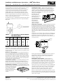
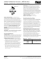
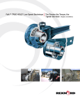
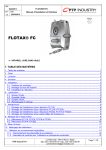
®
a good name in industry
RAM® Mixer Drives • Installation and Maintenance Instructions
Types MDX, MDXQ, MDXT, MDH & MDHQ • Sizes 300 thru 900
(Page 1 of 8)
How to Use This Manual
This manual provides detailed instructions on installation and
maintenance of gear drives and couplings. Use the table of
contents below to locate required information.
CAREFULLY FOLLOW THE INSTRUCTIONS IN THIS
MANUAL FOR OPTIMUM PERFORMANCE AND TROUBLE
FREE SERVICE.
MDXU
Table of Contents
Installation Instructions . . . . . . . . . . . . . . . . . . Pages 1 thru 3
Shaft Connections . . . . . . . . . . . . . . . . . . . . . . . Pages 3 & 4
Tightening Torques . . . . . . . . . . . . . . . . . . . . . . . . . . Page 4
Lubrication Recommendations . . . . . . . . . . . . Pages 4 thru 8
Preventive Maintenance. . . . . . . . . . . . . . . . . . . . . . . Page 8
Stored & Inactive Gear Drives . . . . . . . . . . . . . . . . . . Page 8
MDXQ
MDHQ
Introduction
Credit for long service and dependable operation of a gear
drive is often given to the engineers who designed it, or the
craftsmen who constructed it, or the sales engineer who
recommended the type and size. Ultimate credit belongs to the
mechanic on the job who worked to make the foundation rigid
and level, who accurately aligned the shafts and carefully
installed the accessories, and who made sure that the drive
received regular lubrication. The details of this important job
are the subject of this manual.
NAMEPLATE — Operate Falk gear drives only at horsepower,
speed and ratio shown on nameplate. Before changing any
one of these, submit complete nameplate data and new
application conditions to the Factory for correct oil level, parts
and application approval.
DISASSEMBLY & ASSEMBLY — Disassembly & assembly
instructions and parts guides are available from the Factory or
Falk Representatives. When requesting information, please give
complete data from the nameplate on the gear drive; Model,
M.O. Number, Date, RPM, and Ratio.
WARNING: Consult applicable local and national safety
codes for proper guarding of rotating members. Lock out power
source and remove all external loads from drive before
servicing drive or accessories.
Warranty
The Falk Corporation (the “Company”) warrants that, for a
period of one year from the date of shipment, the product
described herein will deliver successfully its rated output as
indicated on the nameplate, provided, it is properly installed
and maintained, correctly lubricated, and operated in the
environment and within the limits of speed, torque or other
load conditions for which it was sold. Such product is expressly
not warranted against failure or unsatisfactory operation
resulting from dynamic vibrations imposed upon it by the drive
system in which it is installed unless the nature of such
vibrations has been fully defined and expressly accepted in
writing by the Company as a condition of operation.
MDXT
MDXD
Installation Instructions
The following instructions apply to all standard Falk Type MDX and
MDH gear drives. If a drive is furnished with special features, refer
to the supplementary instructions shipped with the drive. The MDX
Mixer is a right angle drive with vertical or horizontal output shaft
designed primarily for mixer service. The basic drive is designed for
pedestal mounting but may be furnished with a Falk mounted (bolt
on) adapter base or with an independently supported output (stub)
shaft and pedestal base (MDXT).
The standard drive may be furnished with a solid output shaft or
hollow output shaft. A low speed shaft drywell feature is
standard on vertical drives with either solid shaft extension
down and with hollow shaft and may be furnished as an option
on solid shaft extension up drives. Upper low speed bearings of
all vertical drives and lower low speed bearings of drives with
drywells are grease lubricated.
The MDXT drive is furnished with an output (stub) shaft
independently supported by spherical roller bearings in
externally mounted upper and lower bearing members (upper
bearing cage and pedestal base). The output shaft is flexible
coupling connected to the drive hollow shaft and the drive
foundation is integral with the pedestal base. The standard
MDXT output shaft is furnished with an integral coupling flange.
The low speed shaft extension ends of solid shaft drives are
drilled and tapped (2 holes) for thrust coupling keeper plates,
refer to “Shaft Connections” on Page 3.
MOUNTING — CAUTION: Mount drive only in the position
for which it was ordered, i.e., horizontal base for MDX or
horizontal low speed shaft for MDH. If it is necessary to mount
the drive in a different position from that for which it was
ordered, consult The Falk Corporation for changes necessary to
provide proper lubrication.
The Falk Corporation, P.O. Box 492, Zip 53201-0492
3001 W. Canal St., Zip 53208-4200, Milwaukee, WI USA Telephone: 414-352-3131
Fax: 414-937-4359 e-mail: [email protected] web: www.falkcorp.com
308-050
March 1995
Supersedes 9-90
Installation and Maintenance Instructions • RAM® Mixer Drives
(Page 2 of 8)
Sizes 300 thru 900 • Types MDX, MDXQ, MDXT, MDH & MDHQ
The basic RAM drive is designed for pedestal mounting (customer
supplied) with a bolt circle on the housing underside that is
concentric about the low speed shaft. The lower low speed seal
cage or end cover has a close tolerance machined outside
(register) diameter for accurate positioning of the drive on the
pedestal. Refer to Table 1 for housing mounting bolt circle data.
The Falk supplied adapter base (optional) is registered on the
lower L.S. seal cage or end cover and uses the same bolting as
used for customer pedestal mounting.
The MDXT drive with an independently supported output shaft is
supplied with a pedestal base which has a unique foundation
bolt pattern.
TABLE 1 — Unit Housing to Pedestal/Adapter
Base Bolting Data
Unit Size
Dia. - Housing
Quantity Fastener Size Bolt Circle Register
Nom
Thread Depth
300
400
500
600
700
800
900
8
8
12
12
12
12
12
.500-13 UNC
.625-11 UNC
.625-11 UNC
.625-11 UNC
.750-10 UNC
.875-9 UNC
.875-9 UNC
11.50
12.00
13.00
15.00
17.00
20.00
20.00
8.500
9.500
10.250
11.500
13.000
15.000
15.000
308-050
March 1995
Supersedes 9-90
a good name in industry
FOUNDATION, STEEL — When mounting gear drive on
structural steel, it is recommended that an engineered design be
utilized for a pedestal, adapter base or bed to provide sufficient
rigidity, to prevent induced loads from distorting the housing and
causing gear misalignment. In the absence of an engineered
design, it is recommended
that a base plate, with
thickness equal to or
greater than the thickness
of the drive feet, be
securely bolted to steel
supports and extend under
the entire drive as
illustrated. Refer to
“Fastener Tightening
Torques” on Page 4.
GEAR DRIVE ALIGNMENT — Align drive with driven equipment
by placing broad, flat shims under all mounting pads. Start at the
low speed shaft end and level across the length and then the width
of the drive. Check with a feeler gauge to make certain that all pads
are supported to prevent distortion of housing when drive is bolted
down. After drive is aligned with driven equipment and bolted down,
align prime mover to drive input shaft. Refer to Page 3 for coupling
alignment.
If equipment is received from Falk mounted on a bedplate, the
components were accurately aligned at Falk with the bedplate
mounted on a large, flat assembly plate. Shim under the
bedplate foot pads until the gear drive is level and all feet are
in the same plane.
Leveling
Surface
.72
.90
.90
1.12
1.12
1.12
1.12
WELDING — Do not weld on the gear drive or accessories
without prior approval from The Falk Corporation. Welding on
the drive may cause distortion of the housing or damage to the
bearings and gear teeth. Welding without prior approval could
void the warranty.
EFFECTS OF SOLAR ENERGY — If the gear drive operates in
the sun at ambient temperatures over 100°F(38°C), then special
measures should be taken to protect the drive from solar energy.
This protection can consist of a canopy over the drive or reflective
paint on the drive. If neither is possible, a heat exchanger or other
cooling device may be required to prevent the sump temperature
from exceeding the allowable maximum.
FOUNDATION, GENERAL — To facilitate oil drainage, elevate
the gear drive foundation above the surrounding floor level. If
desired, replace the drive oil drain plug with a valve, but provide a
guard to protect the valve from accidental opening or breakage.
FOUNDATION, CONCRETE — If a concrete foundation is used,
allow the concrete to set firmly before bolting down the gear drive. For
the best type of mounting, grout
structural steel mounting pads
into the mounting base, as
illustrated, rather than grouting
the drive directly into the
concrete.
®
Shims
Check high speed shaft coupling alignment. If the coupling is
misaligned, the bedplate is shimmed incorrectly. Re-shim
bedplate and recheck high speed coupling alignment. If
necessary, realign motor.
HORIZONTAL OUTPUT SHAFT — When the drive is
mounted for horizontal output, the torque reaction can be
transmitted through the adapter base, pedestal, tie rod, or a
combination thereof. The Falk tie rod may be mounted above
or below the drive and its angular position may vary as shown.
For other positions, refer to the factory. If it is necessary to
shorten the tie rod, cut off the excess from either threaded end.
The support to which the clevis bracket is to be fastened must
sustain the torque reaction shown in Table 2. Use Grade 5
fasteners to anchor the clevis bracket; tighten to torques
specified in “Fastener Tightening Torques” on Page 4.
Bolt the tie rod to both the clevis bracket and the drive anchor
bracket and tighten bolts until seated against the brackets. DO
NOT bend the brackets. Clearance between the clevis brackets
and tie rod is required.
The Falk Corporation, P.O. Box 492, Zip 53201-0492
3001 W. Canal St., Zip 53208-4200 Milwaukee, WI USA Telephone: 414-342-3131
Fax: 414-937-4359 e-mail: [email protected] web: www.falkcorp.com
®
a good name in industry
RAM® Mixer Drives • Installation and Maintenance Instructions
Types MDX, MDXQ, MDXT, MDH & MDHQ • Sizes 300 thru 900
(Page 3 of 8)
COUPLING CONNECTIONS — The performance and life of
any coupling depends largely upon how well the coupling is
installed and serviced. Refer to the coupling manufacturer’s
manual for specific instructions.
CORRECT METHOD
Heat interference fitted
coupling hubs, pinions,
sprockets or pulleys to a
maximum of 275°F
(135°C) and slide onto
gear drive shaft.
INCORRECT METHOD
DO NOT drive coupling
hub, pinion, sprocket or
pulley onto the shaft. An
endwise blow on the
shaft/coupling may damage
gears and bearings.
— CAUTION—
DO NOT HAMMER
FOR “HORIZONTAL OUTPUT SHAFT”
TABLE 2 — Load Reaction Through Tie Rod
Unit Size
Load (lbs.)
300
400
500
600
700
800
900
5000
7000
9000
10000
14000
17000
17000
MOTOR BRACKETS — The weight, location and starting
torque of the motor will cause some brackets to deflect
downward and to twist. This movement is within allowable
engineered limits for motor-drive selections from the Falk
bulletin. If the customer considers the movement excessive,
jackscrew supports for the bracket extension are available from
Falk. To compensate for deflection caused by heavy motors
AND to get CORRECT COUPLING ALIGNMENT, use more
shims under the rear motor feet than the front feet.
Motors and other components mounted on motor plates or
motor brackets may become misaligned during shipment.
ALWAYS check alignment after installation. Refer to “Shaft
Connections” for coupling alignment instructions.
FALK COUPLINGS — (Except fluid type) Detailed installation
manuals are available from the Factory, your local Falk
Representative or Distributor—just provide size and type
designations stamped on the coupling. For lubricant
requirements and a list of typical lubricants meeting Falk
specifications, refer to appropriate coupling service manual.
FLANGED TYPE RIGID COUPLINGS — are typically used on
drives with vertical output shafts. The low speed shaft extension
ends of the solid shaft drives are drilled and tapped to
accommodate coupling keeper plates. Tightening torques for
fasteners, including keeper plate fasteners are listed in Table 3.
TABLE 3 — Rigid Coupling Selection &
Keeper Plate Fastener Data
Drive
Size
Rigid
Coupling
Size H
300
400
500
600
700
800
900
1020G82
1025G82
1030G82
1035G82
1040G82
1045G82
1045G82
Coupling Flange Keeper Plate Fastener Data †
Fastener
Tightening
Size
Bolt Circle
Torque lb-in.
900
1800
1800
3000
3000
3000
3000
.500-13 UNC
.500-13 UNC
.625-11 UNC
.625-11 UNC
.750-10 UNC
1.125-7 UNC
1.125-7 UNC
2.00
2.50
2.75
3.75
4.00
4.50
4.50
H The outside diameter of the selected rigid coupling is less than the seal cage
register diameter to accommodate pedestal mounting with coupling hub installed.
Shaft Connections
WARNING: Provide suitable guards in accordance with
OSHA standards.
SHRINK DISC CONNECTIONS — Shrink disc assemblies used
on drives with a horizontal and hollow low speed shaft, require
special installation procedures and have metric fasteners. Refer to
the supplementary instructions supplied with the shrink disc
assembly.
† Torque to Table 4 metal to metal values.
FALK FLUID COUPLINGS — Refer to the installation manual
furnished with the fluid coupling for
installation, alignment and startup
instructions.
GAP & ANGULAR ALIGNMENT — If
possible, after mounting coupling hubs,
position the driving and driven equipment
so that the distance between shaft ends is
equal to the coupling gap. Align the
STEELFLEX ILLUSTRATED
shafts by placing a spacer block, equal in
thickness to required gap, between hub
faces, as shown above, and also at 90° intervals around the hub.
Check with feelers.
The Falk Corporation, P.O. Box 492, Zip 53201-0492
3001 W. Canal St., Zip 53208-4200, Milwaukee, WI USA Telephone: 414-352-3131
Fax: 414-937-4359 e-mail: [email protected] web: www.falkcorp.com
308-050
March 1995
Supersedes 9-90
Installation and Maintenance Instructions • RAM® Mixer Drives
(Page 4 of 8)
Sizes 300 thru 900 • Types MDX, MDXQ, MDXT, MDH & MDHQ
OFFSET ALIGNMENT — Align driving
and driven shafts so that a straight edge
will rest squarely on both couplings hubs
as shown to the right and also at 90°
intervals. Tighten foundation bolts of the
connected equipment and recheck
alignment and gap. The Steelfex coupling STEELFLEX ILLUSTRATED
at the upper end of the MDXT output shaft
is self aligning and is lubricated with LTG
(Long Term Grease) at the Factory.
SPROCKETS, PULLEYS OR SHEAVES — Mount power
take-offs as close to the gear drive housing as possible to
avoid undue bearing load and shaft deflection.
Align the output shaft of the gear drive square and parallel with the
driven shaft by placing a straightedge across the face of the sprockets
or sheaves as illustrated.
Check horizontal shaft
WRONG
RIGHT
alignment by placing one
leg of a square against
the face of the sheave or
sprocket with the spirit
level on the horizontal leg
of the square.
GEAR DRIVE WALL
LEVEL
SQUARE AND
PARALLEL
DO NOT over tighten belts or chains. Adjust chains to
manufacturers’ specifications. Adjust belts as follows:
The ideal tension is the lowest tension at which the belt will not
slip under peak load conditions. Check the belt tension
frequently during the first 24 to 48 hours of run-in operation.
Over tightening belts shortens belt and bearing life. Keep belts
free from foreign material which may cause slippage. Inspect
the V–belt periodically; tighten the belts if they are slipping.
PINION MOUNTING — Mount pinion as close to the drive
as possible to avoid undue bearing load and shaft deflection.
Refer to the Factory for pinion alignment instructions.
Use the tightening torque values specified in Table 4, for
fastening Falk gear drives, motors, keeper plates and accessories
to their mounting surfaces with non-lubricated fasteners. DO NOT
use these values for “torque locking” fasteners or for fastening
components with aluminum feet or with soft gaskets or vibration
dampers on the mounting surface. If the tightening torque exceeds
the capacity of the torque wrench, use a torque multiplier. Use
Grade 5 fasteners for diameters through 1.50", for larger diameter
fasteners, use ASTM A-354 Grade BC.
March 1995
Supersedes 9-90
a good name in industry
TABLE 4 — Tightening Torques (lb-in) ± 5% —
(DO NOT Lubricate Fasteners)
Thread
Dia-UNC
Metal to
Metal
Metal to
Concrete
.250-20
.3125-18
.375-16
.500-13
.625-11
.750-10
90
185
330
825
1640
2940
70
145
255
640
1280
2290
Thread
Dia-UNC
Metal to
Metal
Metal to
Concrete
.875-9
1.000-8
1.125-7
1.250-7
1.375-6
1.500-6
4560
6800
8900
12600
16500
22100
3750
5600
7000
10000
13000
17500
Lubrication Recommendations
Carefully follow lubrication instructions on the gear drive
nameplate, warning tags and installation manuals furnished
with the gear drive.
Lubricants listed in this manual are typical ONLY and should
not be construed as exclusive recommendations. Industrial type
petroleum based rust and oxidation inhibited (R & O) gear
lubricants or industrial type sulfur-phosphorus extreme pressure
(EP) gear lubricants are the recommended lubricants for
ambient temperatures of 15°F to 125°F(-9°C to +52°C).
For drives operating outside the above temperature range refer
to “Synthetic Lubricants” paragraphs, Page 5. Synthetic
lubricants can also be used in normal climates.
VISCOSITY (IMPORTANT) — The proper grade for R & O and
EP lubricants is found in Table 5. For cold climate conditions refer
to Table 8, Page 6 and the “Synthetic Lubricant” paragraphs.
Select a lubricant which has a pour point at least 10°F (5.5°C)
below the expected minimum ambient starting temperature.
Usable temperature ranges can sometimes be widened if specific
application conditions are known.
If a gear drive operates in a typical indoor environment where
the ambient temperature is within 70°F to 125°F (21°C to
52°C), the oil viscosity should be increased one AGMA grade
above that shown for the 50°F to 125°F(10°C to 52°C) range.
That is, an AGMA Number 6 or 7 should be substituted for a 5
or 6 respectively, under this ambient condition.
TABLE 5 — Viscosity Grade Recommendations
for R & O or EP Lubricants
Normal Climates
Output RPM
15° to 60°F
(-9° to +16°C)
ISO-VG
Fastener Tightening Torques
308-050
®
Output RPM Below 80
Output RPM 80 & Above
150
150
50° to 125°F
(10° to 52°C)
AGMA ISO-VG
4
4
320
220
AGMA
6
5
The Falk Corporation, P.O. Box 492, Zip 53201-0492
3001 W. Canal St., Zip 53208-4200 Milwaukee, WI USA Telephone: 414-342-3131
Fax: 414-937-4359 e-mail: [email protected] web: www.falkcorp.com
RAM® Mixer Drives • Installation and Maintenance Instructions
®
Types MDX, MDXQ, MDXT, MDH & MDHQ • Sizes 300 thru 900
a good name in industry
(Page 5 of 8)
Petroleum Based Lubricants
R & O GEAR LUBRICANTS (Table 9) — Industrial type
petroleum based rust and oxidation inhibited (R & O ) gear
lubricants are the most common and readily available general
purpose gear lubricants.
EXTREME PRESSURE (EP) LUBRICANTS (Table 7) — For
highly loaded gear drives or drives loaded in excess of original
estimates, industrial type petroleum extreme pressure lubricants
are preferred. The EP lubricants currently recommended are of
the sulphur-phosphorus type.
WARNING: EP LUBRICANTS IN FOOD PROCESSING
INDUSTRY — EP lubricants may contain toxic substances and
should not be used in the food processing industry without the
lubricant manufacturers’ approval. Lubricants which meet USDA
“H1” classification are suitable for food processing
applications.
MDH
FIGURE 1
Synthetic lubricants of the polyalphaolefin type are
recommended for cold climate operation, high temperature
applications, extended temperature range (all season)
operation and/or extended lubricant change intervals. The
proper viscosity grade of synthetic lubricant is given in Table 8.
WARNING: SYNTHETIC LUBRICANTS IN FOOD
PROCESSING INDUSTRY — Synthetic lubricants may contain
toxic substances and should not be used in the food processing
industry without the lubricant manufacturers’ approval. Lubricants
which meet USDA “H1” classification are suitable for food
processing applications.
FIGURE 2
H.S. SHAFT ABOVE L.S.
SHAFT CENTERLINE
OIL FILL
L.S. SHAFT ABOVE H.S.
SHAFT CENTERLINE
VENTED DIPSTICK
L.S. BEARING
GREASE FITTINGS
MDX
Synthetic Lubricants
MDH
OIL DRAIN
NOTE: OIL FILL AND DIPSTICK POSITIONS
REVERSED ON SIZES 800 & 900
AIR VENT & FILL
DIPSTICK
MDH
Oil Levels
Fill the drive with oil to the level indicated on the oil level
dipstick. Approximate oil capacities (for ordering oil) are listed
in Table 6.
Before starting, if conditions permit, rotate the input shaft by
hand to check for any obstruction. Then start the drive and
allow it to run without a load for several minutes. Shut down
and recheck oil level. Add oil to compensate for cooler,
filter, etc., oil capacities. If everything is satisfactory, the
drive is ready for operation.
DRAIN PLUG
TABLE 6 — Approximate Oil Capacity —
Gallons
Drive
Size
Type
MDX
300
400
500
600
700
800
7
9
13
19
24
44
Type MDH
Figure 1
Double
11
10
13
19
24
43
Figure 2
MDXT
Triple & Quad. All Reductions
14
17
25
37
45
81
11
13
18
26
33
59
The Falk Corporation, P.O. Box 492, Zip 53201-0492
3001 W. Canal St., Zip 53208-4200, Milwaukee, WI USA Telephone: 414-352-3131
Fax: 414-937-4359 e-mail: [email protected] web: www.falkcorp.com
308-050
March 1995
Supersedes 9-90
Installation and Maintenance Instructions • RAM® Mixer Drives
(Page 6 of 8)
®
Sizes 300 thru 900 • Types MDX, MDXQ, MDXT, MDH & MDHQ
TABLE 8 — Polyalphaolefin Type
Synthetic Lubricants H
TABLE 7 — Extreme Pressure Lubricants
Maximum Operating Temperature
200°F(93°C)
Manufacturer
Lubricant
Amoco Oil Co.
BP Oil Co.
Chevron U.S.A. Inc.
Citgo Petroleum Corp.
Permagear/Amogear EP
Energear EP
Gear Compounds EP
Citgo EP Compound
Conoco Inc.
Exxon Co. U.S.A.
E.F. Houghton & Co.
Imperial Oil Ltd.
Gear Oil
Spartan EP
MP Gear Oil
Spartan EP
Kendall Refining Co.
Keystone Div. Pennwalt Corp.
Lyondell Petrochemical (ARCO)
Mobil Oil Corp.
Petro–Canada Products
Kendall NS-MP
Keygear
Pennant NL
Mobilgear
Ultima EP
Phillips 66 Co.
Shell Oil Co.
Shell Canada Limited
Sun Oil Co.
Texaco Lubricants
Philgear
Omala Oil
Omala Oil
Sunep
Meropa
Unocal 76 (East & West)
Valvoline Oil Co.
a good name in industry
AGMA Viscosity Grade
...
2
4
5
ISO Viscosity Grade
32
68
150
220
cSt @ 40° C
28.8–35.2
61.2–74.8
135–165
198–242
SSU @ 100° F
135–164
284–347
626–765
918–1122
Viscosity
Ambient Temperature – 30° to+10°F – 15° to + 50°F 0° to+ 80°F +10° to+125°F
(–3° to –12°C) (–26° to +10°C) (–18° to +27°C) (–12° to +52°C)
Range †
Manufacturer
Lubricant
Chevron USA, Inc.
Conoco, Inc.
...
Syn. Gear
Lube
Tegra 220
...
Syncon 32
Syncon 68
...
...
CP–4620–
32
CP–4620–
68
CP–4620–
150
CP–4620–
220
CP–4630–
32 ‡
CP–4630–
68 ‡
CP–4630–
150 ‡
CP–4630–
220 ‡
Exxon Co. USA
...
...
Spartan
Synthetic
EP 150 ‡
Spartan
Synthetic
EP 220 ‡
Mobil Oil Corp.
SHC 624
...
SHC 626
...
CPI Engineering
Services, Inc.
Extra Duty NL Gear Lube
AGMA EP
...
SHC 629
SHC 630
Mobilgear
SHC 150 ‡
Mobilgear
SHC 220 ‡
H Minimum viscosity index of 130. Consult lubricant supplier/manufacturer for
maximum operating temperature.
† With complete application information, temperature range can sometimes be
extended, consult Factory.
‡ Extreme Pressure EP lubricants contain phosphorus.
TABLE 9 — Petroleum Based R & O Gear Oils (Maximum operating temperature of lubricants 200°F(93°C)
AGMA Viscosity Grade
3
4
5
6
7
ISO Viscosity Grade
100
150
220
320
460
90-110
135-165
198-242
288-352
414-506
417-510
626-765
918-1122
1335-1632
1919-2346
Lubricant
Lubricant
Lubricant
Lubricant
Viscosity
cSt @ 40° C
SSU @ 100° F
Manufacturer
Lubricant
Amoco Oil Co.
BP Oil Co.
Chevron U.S.A., Inc.
Citgo Petroleum Corp.
Amer.Ind. Oil 100
Turbinol T–100
Machine Oil AW 100
Citgo Pacemaker 100
Amer.Ind. Oil 150
.....
Machine Oil AW 150
Citgo Pacemaker 150
Amer.Ind. Oil 220
Energol HLP-HD 220
Machine Oil AW 220
Citgo Pacemaker 220
Amer. Ind. Oil 320
.....
Machine Oil AW 320
Citgo Pacemaker 320
Amer. Ind. Oil 460
.....
.....
Citgo Pacemaker 460
Conoco Inc.
Exxon Company, U.S.A.
Houghton International, Inc.
Imperial Oil Ltd.
Dectol R&O Oil 100
Teresstic 100
Hydro–Drive HP 500
Teresso 100
Dectol R&O Oil 150
Teresstic 150
Hydro–Drive HP 750
Teresso 150
Dectol R&O Oil 220
Teresstic 220
Hydro–Drive HP 1000
Teresso 220
Dectol R&O Oil 320
Teresstic 320
.....
Teresso 320
Dectol R&O Oil 460
Teresstic 460
.....
.....
Kendall Refining Co.
Keystone Lubricants
Lyondell Petrochemical (ARCO)
Mobil Oil Corp.
Petro–Canada Products
Kenoil R&O AW 100
KLC–30
Duro 100
DTE Oil Heavy
Harmony 100
Four Seasons AW 150
KLC–40
Duro 150
DTE Oil Extra Heavy
Harmony 150 or 150D
.....
KLC-50
Duro 220
DTE Oil BB
Harmony 220
.....
.....
Duro 320
DTE Oil AA
Harmony 320
.....
.....
.....
DTE Oil HH
.....
Phillips 66 Co.
Shell Oil Co.
Shell Canada Limited
Texaco Lubricants
Magnus Oil 100
Morlina 100
Tellus 100
Regal Oil R&O 100
Magnus Oil 150
Morlina 150
Tellus 150
Regal Oil R&O 150
Magnus Oil 220
Morlina 220
Tellus 220
Regal Oil R&O 220
Magnus Oil 320
Morlina 320
Tellus 320
Regal Oil R&O 320
.....
Morlina 460
.....
Regal Oil R&O 460
Unocal 76 (East)
Unocal 76 (West)
Valvoline Oil Co
Unax RX 100
Turbine Oil 100
Valvoline AW ISO 100
Unax RX 150
Turbine Oil 150
Valvoline AW ISO 150
Unax RX 220
Turbine Oil 220
Valvoline AW ISO 220
Unax AW320
Turbine Oil 320
Valvoline AW ISO 320
Turbine Oil 460
Turbine Oil 460
.....
308-050
March 1995
Supersedes 9-90
The Falk Corporation, P.O. Box 492, Zip 53201-0492
3001 W. Canal St., Zip 53208-4200 Milwaukee, WI USA Telephone: 414-342-3131
Fax: 414-937-4359 e-mail: [email protected] web: www.falkcorp.com
®
a good name in industry
RAM® Mixer Drives • Installation and Maintenance Instructions
Types MDX, MDXQ, MDXT, MDH & MDHQ • Sizes 300 thru 900
Lubricant Changes
OIL ANALYSIS REPORT— Checking oil condition at regular
intervals is recommended. In the absence of more specific
limits, the guidelines listed below may be used to indicate when
to change oil:
1. Water content is greater than 0.05% (500 ppm).
2. Iron content exceeds 150 ppm.
3. Silicon (dust/dirt) exceeds 25 ppm.
4. Viscosity changes more than 15%.
PETROLEUM LUBRICANTS — For normal operating
conditions, change gear oils every 6 months or 2500 operating
hours, whichever occurs first. If the drive is operated in an area
where temperatures vary with the seasons, change the oil
viscosity grade to suit the temperature, refer to Table 5 on
Page 4. Lubricant suppliers can test oil from the drive
periodically and recommend economical change schedules.
SYNTHETIC LUBRICANTS — Synthetic lube change intervals
can be extended to 8000-10,000 hours depending upon
operating temperatures and lubricant contamination. Laboratory
analysis is recommended for optimum lubricant life and gear
drive performance. Change lube with change in ambient
temperature, if required. Refer to Table 8 on Page 6.
Lubrication Systems
SPLASH LUBRICATED UNITS — Standard MDX drives are splash
lubricated. The lubricant is picked up by the revolving elements and
distributed to all bearings except the L.S. shaft bearings and gear meshes.
UNITS WITH WATER COOLED HEAT EXCHANGERS —
Install a shut-off or control valve in the water-line TO the heat
exchanger to regulate the water flow through the exchanger.
Also install a water flow gauge between the control valve and
the exchanger to determine actual flow rate. Discharge water to
an OPEN DRAIN to prevent back pressure. If drive is equipped
with an external pump, check immediately after starting to see
that pump is circulating oil properly.
NON-STANDARD MOUNTING — For drives with
non-standard mounting, including tilted, refer to instructions
provided with the drive for oil levels and bearing lubrication.
Bearing & Seal Greases
All MDX drives have one or two grease lubricated low speed shaft
bearings and all drives have a grease purged high speed shaft oil
seal. All MDXT drives have four grease lubricated low speed shaft
bearings (2 drive, 2 output shaft), the drive upper low speed
grease fitting is accessed by removal of the labeled inspection
cover. Whenever changing oil in the drive regrease bearings and
seal with one of the NLGI #2 greases listed in Table 10.
Some of these greases are of the EP type and may contain toxic
substances not allowed in the food processing industry. A
grease that meets the USDA “H1” classification is suitable for
food processing applications.
GREASE LUBRICATED BEARINGS — All upper low speed shaft
bearings and the lower low speed shaft bearings of drives with drywell
are grease lubricated, in addition, the output shaft bearings of MDXT
drives are grease lubricated. When changing oil in the drive, grease
bearings with a NLGI #2 bearing grease selected from Table 10.
Regrease these bearings as part of the standard maintenance
program. Where process requirements permit, regreasing output shaft
bearings of MDXT drives with a NLGI #2 EP (Extreme Pressure)
(Page 7 of 8)
TABLE 10 — Greases for Grease Lubricated
Bearings & Grease Purged Seals
(0° to 200°F(-18° to +93°C)
Manufacturer
Lubricant
Amoco Oil Co.
BP Oil Co.
Chevron U.S.A., Inc.
Citgo Petroleum Corp.
Amolith Grease No. 2
Energrease LS–EP2
Industrial Grease Medium
Premium Lithium Grease No. 2
Conoco Inc.
Exxon Company, U.S.A.
E.F. Houghton & Co.
Imperial Oil Ltd.
EP Conolith Grease No. 2
Unirex N2
Cosmolube 2
Unirex N2L
Kendall Refining Co.
Keystone Div. Pennwalt Corp.
Lyondell Petrochemical (ARCO)
Mobil Oil Corp.
Mobil Oil Corp
Petro–Canada Products
Multi–Purpose Lithium Grease L421
Zeniplex 2
Litholine H EP 2 Grease
Mobilith 22
Mobilith SHC 460 H
Multipurpose EP2
Phillips 66 Co.
Shell Oil Co.
Shell Canada Limited
Sun Oil Co.
Texaco Lubricants
Philube Blue EP
Alvania Grease 2
Alvania Grease 2
Ultra Prestige EP2
Premium RB Grease
Unocal 76 (East & West)
Valvoline Oil Co.
Unoba EP2
Multilube Lithium EP Grease
H High performance synthetic alternate.
TABLE 11 — L.S. Shaft Bearing Regreasing
Capacity (Ounces)†
Solid Shaft
Drive
Size
Bearing
Location
300
Upper
Lower
Ext. Down
3
3
Hollow
Shaft
MDXT
Stub Shaft
3
3
2
2
400
Upper
Lower
3
3
3
5‡
3
3
2
2
500
Upper
Lower
4
3
4
5‡
4
3
3
3
600
Upper
Lower
4
3
4
6‡
4
3
4
4
700
Upper
Lower
6
5
6
11 ‡
6
5
6
5
800
Upper
Lower
12
10
12
16 ‡
12
10
12
8
900
Upper
Lower
12
10
12
16 ‡
12
10
12
8
Ext. Up
3
3‡
† The quantities of grease (in ounces) listed in the table are for relubrication of
the bearings which have been originally packed with grease in assembly and
are an approximate guide. The actual requirements are dependent upon load,
speed and operating conditions and can only be determined from experience
of the equipment operator.
‡ These bearings are normally oil lubricated. Quantity listed is for grease
lubrication option.
grease is recommended. Remove pressure relief plugs while
regreasing MDXT output shaft bearings, then replace. The MDXT drive
upper low speed shaft bearing grease fitting is accessed by removing
the upper bearing cage inspection cover. Before installing a drive note
the location of all of the bearing grease fittings and grease labels for
future maintenance reference. Note that some fittings may be ABOVE
the oil level line and others BELOW. If a grease fitting will become
inaccessible after the drive is installed, replace the fitting with a pipe
extension (and the fitting) so that the grease fitting will be in an
accessible location after the drive is installed.
The Falk Corporation, P.O. Box 492, Zip 53201-0492
3001 W. Canal St., Zip 53208-4200, Milwaukee, WI USA Telephone: 414-352-3131
Fax: 414-937-4359 e-mail: [email protected] web: www.falkcorp.com
308-050
March 1995
Supersedes 9-90
Installation and Maintenance Instructions • RAM® Mixer Drives
(Page 8 of 8)
Sizes 300 thru 900 • Types MDX, MDXQ, MDXT, MDH & MDHQ
GREASE LUBRICATED SEALS — Most gear drives are
furnished with grease purged seals on the H.S. shaft which
minimize the entry of contaminants and abrasive dusts into the
drive or backstop. Gear drives are shipped with NLGI #2
grease in the seal housing cavities unless otherwise specified. If
grease could contaminate the product, as in the food and drug
industries, it should be removed. A grease that meets USDA
“H1” classification is suitable for food processing applications.
Periodically (at least every six months) depending upon the
frequency and degree of contamination, purge contaminated
grease from seals by slowly pumping fresh bearing grease
through the seal, WITH A HAND GREASE GUN, until fresh
grease flows out along the shaft. Wipe off purged grease.
CAUTION: Rapid regreasing with a power grease gun can force
grease inward past the seals and plug the oil drain back system
causing seal leaks.
COUPLINGS — Lubricate Falk Steelflex couplings in accordance
with instructions in Manual 428-010 and Falk Gear couplings in
accordance with instructions in Manual 458-010
Preventive Maintenance
AFTER FIRST WEEK — Check alignment of the total system and
realign where necessary. Also, tighten all external bolts and plugs
where necessary. DO NOT readjust the internal gear or bearing
settings in the drive, these were permanently set at the Factory.
AFTER FIRST MONTH’S SERVICE — Proceed as follows:
1. Operate drive until old sump oil reaches normal operating
temperature. Shut the drive down and drain immediately.
2. Immediately flush drive with an oil of the same type and
viscosity grade as the original charge (warmed to
approximately 100°F (38°C) in cold weather). Rapidly pour or
pump a charge equal to 25-100% of the initial fill volume
through the drive or until clean oil flows through the drain.
3. Close the drain and refill the drive to the correct level with
new or reclaimed oil of the correct type and viscosity. If
determined to be in good condition by the supplier,
reclaimed oil may be reused if it is filtered through a 40
micron or finer filter.
March 1995
Supersedes 9-90
a good name in industry
PERIODICALLY — Carefully check the oil level of the drive
when it is stopped and at ambient temperature, add oil if
needed. If the oil level is ABOVE the high level mark on the
dipstick, have the oil analyzed for water content. Moisture in
the oil may indicate that the heat exchanger or a seal is
leaking. If so, replace the defective part immediately and
change the oil. DO NOT fill above mark indicated as leakage
or undue heating may result. Also check coupling alignment to
make certain that foundation settling has not caused excessive
misalignment. If drive is equipped with a fan, periodically clean
accumulated foreign matter from the fan, fan guard and
deflector to allow adequate air flow.
LUBRICANT CHANGES — Refer to Page 7.
BEARING & SEAL GREASES — Refer to Page 7.
FOR GREASING
SEAL
308-050
®
Stored & Inactive Gear Drives
Each gear drive is protected with rust preventive that will protect
parts against rust for a period of 4 months in an outdoor shelter or
12 months in a dry building after shipment from the Factory.
If a gear drive is to be stored, or is inactive after installation
beyond the above periods, drain oil from housing and spray all
internal parts with a rust preventive oil that is soluble in
lubricating oil or add “Motorstor” ™vapor phase rust inhibitor
at the rate of one ounce per cubic foot of internal drive space
(or 5% of sump capacity) and rotate the shafts several times by
hand. Before operating, drives which have been stored or
inactive must be filled to the proper level with oil meeting the
specifications given in this manual.
Periodically inspect stored or inactive gear drives and
spray or add rust inhibitor every six months, or more
often if necessary. Indoor dry storage is recommended.
Gear drives ordered for extended storage can be treated at the
Factory with a special preservative and sealed to rust-proof
parts for periods longer than those cited previously.
The vent cap and vented dipstick should be replaced with a
plug (vented dipstick and vent cap assembly should be
attached to gear drive for future use) so that the protective rust
inhibiting atmosphere is sealed inside the drive. Install vent cap
and vented dipstick when preparing drive for operation.
Motorstor ™/VCI–10 (Add to Stored or Inactive Units)H
Unit Size
Motorstor™ Ounces Per Unit
300 & 400
500 & 600
700
800 & 900
1
2
3
5
H Product of Daubert Chemical Company, Chicago, IL. (Formerly known as
“Nucle Oil”)
The Falk Corporation, P.O. Box 492, Zip 53201-0492
3001 W. Canal St., Zip 53208-4200 Milwaukee, WI USA Telephone: 414-342-3131
Fax: 414-937-4359 e-mail: [email protected] web: www.falkcorp.com