1
(J
ltt
ul!
F
Cl uJ l!
lft tlt ttt
rllt l', ltt
6aCAO
a- 6- o- o-
OPERATING
AND
SERVICE
MANUAL
\-
355C
355D
355E
355F
VHF ATTENUATOR
U
@
Printed: AU
G
rcE
UST 1980
@
H"=&TJJ
\----
t1r1,at
(.'@c.,@
(,r (tl
(tr ctr
(Jr ('r cn ('r
lrmE
$6-qn
Ct
Model355C/D/E/F
Pa4e 2
GENERAL INFORMATION
This manual contains operating instructions for
Hewlett-Packard Model 355C, 355D, 355E, and 355F
VHF Attenuators. Included in the manual is the information required to install and test these attenuators.
Specifications
Instrument specifications are listed in Table 1. These
specifications are the performance standards or limits
against which the instruments may be tested.
Description
The Hewlett-Packard Model 355C, 355D, 355E,
and 355F Attenuators are 50-ohm, coaxial step attenuators usable from dc to 1 GHz. Models 355C and
3558 provide 0 to 12 dB of attenuation in 1 dB steps.
MODELS 355C and
355E
Attenuation Range: 0 to 12
Attenuation steps: 1 dB.
overall
Accuracy:
M0DELS 3550 and
dB.
0.1 dB at 1000 Hz.
0.25 dB, dc to 500 MHz.
0.35 dB, dc to 1000 MHz.
355F
3bbF
ms.
switching speed: 6b
Required Solenoid Power: +15 to +18 Vdc, U8
M0DELS 355c/E and
3550/F
MlIz.
(nominal).
Frequency Range: dc to 1000
Impedance: 50 ohms
In the 355E and 355F power must be continuously
applied to the solenoid to actuate the microswitch
(i.e., to insert an attenuator section). Each solenoid
draws approximately 0.1A at 15 Vdc.
Warranty
Attenuators are warranted only when they are operated within their specifications, especially power
handling capability. Any attenuators returned to
Hewlett-Packard under warranty will be examined
carefully to determine if the failure was due to improper use. Be sure to observe the following caution.
Specifications
v
Maximum SWR (input and output):
1'2 below 250MHz;
1'3 below 500 MHz;
1'5 below 1000 MHz'
Attenuation Range: 0 to 120 dB.
Attenuation Steps: 10 dB.
Overall Accuracy: at 1000 Hz, 0 to 120 dB, 10.3 dB;
Below 1000 MHz, 0 to 90 dB, t1.5 dB;
90 to 120 dB' tg dB'
MSDE1S 3ESE and
t.
v
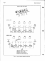
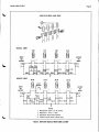
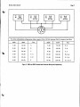
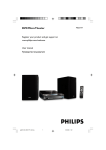
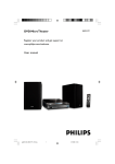
The attenuator sections consist of resistor pi networks which are switched in or bypassed by microswitches. In the 355C and 355D the microswitches
are actuated by cams (see Figure 1). In the 355E
and 355F the microswitches are actuated by solenoids (see Figure 2). The standard RF connectors
are BNC type.
On the rear cover of this manual, below the manual
part number, is a "Microfiche" part number. This
number may be used to order a 100 x 150 mm (4 x
6 in.) microfilm transparency of the manual. The
microfiche package also includes the latest Manual
Changes supplement as well as all pertinent Service
Notes.
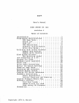
Table
Models 355D and 355F provide 0 to 120 dB of attenuation in 10 dB steps. The 355C and 355D are
manual attenuators. The 355E and 355F are programmable. The schematic for the Model 355C/D is
shown in Figure 1 and that of the Model 355E/F in
Figure 2.
Maximum Residual Attenuation:
Less than 0.2b dB to 100 MHz;
Less than 0.75 dB to 500 MHz;
Less than 1.5 dB to 1000 MIIz.
Maximum Power Dissipation: 0.5w, average.
Maximum Pulse Voltage: 350 Vpk.
remale'
A.
ffi||:[f*PNC'
35bG and
3bED
ffili;i'riu3;[tt
3EbE and 3bEF
]l'trjt;113il:l
,?]".,
in.) 71 mm (2 1U16 in.)
Height: 68 mm (2 1U16
Weight: 0.67 kg (1.5 lb).
\-'"
lDimensions are for general information only. If.dimensions are required for building special enclosures. coltact vour HP office'
Model355C/D/E/F
Page 3
Humidity: l9SVorelative.
Altitude: <4570 m (15 000 ft).
Do not exceed the RF power rating of
0.5W auerage, or 2450W peak with a
maximum pulse width of 200 ps. Do
not connect an attenuator RF input or
output connector to greater than !5 Vdc.
If the attenuator must be connected to a
deuice with a potential gxeater than
x5 Vdc, use a blocking capacitor.
Accessories Supplied
The 355E and 355F programmable attenuators are
supplied with a 7 pin, male connector (HP \2571037) for the solenoid drive input.
Options
Table 2lists the options available.
INSTALLATION
lnitial lnspection
Inspect the shipping container for damage. If the
shipping container or cushioning material is damaged, it should be kept until the contents of the
shipment have been checked mechanically and electrically. A procedure for checking electrical performance is given under "Operator's Check" (see
PERFORMANCE TESTS). If the contents of the
shipment are incomplete, if there is mechanical
damage or defect, or if the instrument does not
pass the electrical performance test, notify the
nearest Hewlett-Packard office. If the shipping container is damaged, or the cushioning material shows
signs of stress, notify the carrier as well as the
Hewlett-Packard office. Keep the shipping materials for the carrier's inspection.
Mating Connectors
Mating RF input and output connectors used with
the attenuators should be:
Standard: Type BNC.
Option 001: Type N.
Option 005: Type TNC.
For the 3558 and 355F, the solenoid drive connector plug is 7-pin male (HP 1251-1037).
Operating Environment
The operating environment of the instrument should
be within the following limitations:
Temperature: 0 to +55'C.
Storage and Shipment
Environment. The instrument should be stored in
dry environment. The following environmental limitations apply to both storage and shipment:
a clean,
-40'C to +75oC
Humidity: 195Vo relative
Altitude: <7620 m (25 000 ft).
Temperature:
Original Packaging. Containers and materials identical to those used in factory packaging are available
through Hewlett-Packard offices. If the instrument
is being retumed to Hewlett-Packard for servicing,
attach a tag indicating the type of service required,
retum address, model number, and full serial number. Also, mark the container FRAGILE to assure
careful handling. In any correspondence, refer to
the instrument by model number and full serial
number.
OPERATING I NSTRUCTIONS
Do not apply RF power greater than
0.5W auerage, or 2450W peak with a nnatcimurn pulse width of 200 ps. If these
limits are exceeded, the Attenuator may
be damaged.
Either RF connector may be used as the input or
output connector, except in the case ofthe 355D/F
driven from a low impedance source. This is because
the leaf switch (Figures 1 and 2) may be closed before the microswitch.opens when the dial is switched
from 50 dB to 60 dB. Should this occur, a momentary shorb is placed across the connector, inviting
damage to either the microswitch or the signal
source. Therefore, if the signal source is subject to
damage by a short, use the rear most connector for
the input. (The dial or solenoid connector is at the
front of the attenuator.) This pads the momentary
shorb with 50 dB of isolation. For the 355E and
355F, wire the solenoid drive plug supplied using
Figure 3 as a wiring guide. An un-energized attenuator solenoid section is 0 dB. Apply +15 to +18 Vdc
(with respect to pin H) to energize an attenuator
solenoid. A programming table is also given in
Figure 3.
Page 4
Model355C/D/E/F
MODELS 355C AND 355D
MODEL 355C
2d8
6dB
3dB
o o
o
l------t
17.61 17.61
MODEL 355D
l0
60 dB
o
o o o
dB
20 dB
30 dB
LEAF SWITCH
NOTES
in 0 dB position.
2. Resistances in ohms e lno/"|.
3. Capacitance values lactory€dlusted.
4. *Asterisk denotes factory selected value.
1.
Figure
Microswitches shown
1. Schematic
Diagrams, Models 355G and 3550
v
Model355C/D/E/F
Page 5
-MODELS 355E AND 355F
MODEL 355E
MODEL 355F
td8
2dB
3d8
s
$
S
60 d8
LEAF
s D1
SWITCH
20 dB
30 dB
s
S
NOTES
1.
Microsruitches shown
2. Resistances
in 0 dB position.
in ohms l!
1lzYol.
3.
Capacitance values factory-adjusted.
4.
*Asterisk denotes factory selected ralue.
Figure 2. Schematic Diagrams, Models 355E and 355F
Model355C/D/E/F
Page 6
Table
2. Attenuator Optiom
Models 355G and 355D
Option 001
option 003
-
-
Type N input and output connectors.
provide panel mountine capability by incorp-
Hfffifl;r1t"H;:rtl?"T
1. The attenuator shaft is 3116" longer, thereby allowing the instrument
shaft to protrude through a 3l\6" panel.
2. Four 6-32 holes are drilled and tapped in the instrument casting to
allow the instrument to be mounted to a panel.
3. A 1 314" dial is added. (This dial is larger than that used with the
standard Models 355C/D.)
NOTE
Panel drilling detail
for rnounting
Option 003 is as follows:
k+k-o.soo
l*l
l.-o,uo
@r@T
e
I
l-
0.562
1.250
0.375 0RtLL
@-d-
Option 005
-
Tlpe
N0.22 DRILL
(FOUR PLACES)
TNC input and output connectors.
Models 355E and 355F
Option 007
-
Adds transistor driver protection circuitry as follows:
CoNNECToR: HP No. 125l-1036
MATING Pl-llG: HP No. 125l-1037
l25l-10{0
l25l-1041
A
ros
ll io cs
lD:
2dB
mdB
AldB
ll lo
HP i,lo. 0491{n4E (4
dB
A6
dB
ll
os
Diode: HP No.
oo
lgolflA 6 REQID)
NOTE
Pin H must be positiue with respect
to other pins.
\J
Model355C/D/E/F
Page 7
(r
To obtain attenuation settings given below, apply +15 to +18 Vdc between Pin H (common) and pins:
C
3558
355F
1dB
10 dB
2dB
3558
355F
A
7dB
70 dB
F,A
20 dB
B
8dB
80 dB
F,B
3dB
30 dB
C
9dB
90 dB
F,C
4dB
40 dB
C,A
10 dB
100 dB
F,C,A
5dB
50 dB
C,B
11 dB
110 dB
F,C,B
6dB
60 dB
F
12 dB
120 dB
F,CrB,A
Figure
s
Pins
3.
355E and 355F Solenoid and Connector Wiring and Programming
Pins
Page 8
Model SSSClDlElF
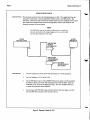
OPERATOR'S CHECK
DESCRIPTION: The attenuator is driven from a 50 ohm signd source at L kHz. The ou@ut level from the
attenuator is detected by a narrow-bandwidth voltmeter (that is, the SWR meter). The
attenuator and detector range switches are stepped together and the variations in level noted.
This vedfies that each attenuator section is being properly switched and checks the lowfrequency accuracy of the attenuator.
NOTE
The SWR Meter used in this check b calibrated for a square-hw
detector and therefore the range changes and ercors (read in dB)
are twice that indicated by the meter.
HP 65I B
TEST OSCILLATOR
t{P 415E
S'IYR
filETER
355C 0R 3550
MANUAL
ATTENUATOR
I
355E 0R 355F
I PROGRAMMABLE
I
ATTENUATOR
s0LEN0l0
DRIVER CIRCUITS
SEE FIGURE 2
PROCEDURE:
1.
Connect equipment as shown above with Attenuator set to 0 dB attenuation.
2.
Set Test Oscillator to 0.3 Vrms at 1 kHz.
3.
Set the SWR Meter input to
XTAL IMPED LOW and the range to 2 dB (expanded)
for 355D or 355F or to 10 dB (with 0 dB expand) for 355C or 355E. Adjust its
bandwidth to the center of the adjustment range. Fine tune oscillator frequency
to obtain the maximum meter indication.
4.
Set attenuator and SWR Meter range switch as listed in table next page, and verify
that the S\ilR Meter indicates within the limits shown.
v
Figure
4.
0perator's Checks (1 of 2)
Model355C/D/E/F
Page 9
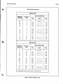
OPERATOR'S CHECKS
355C And 355E
SWR Meter
Range (dB)
Attenuation
10
0
10
1
10
10
(dB)
Meter lndication (dB)
Min.
Actual
Max.
Set to 0.0
,
3
0.45
0.95
1.45
1.95
0.55
1.05
1.55
2.05
0.55
10*
4
12
12
6
12*
74
8
9
0.45
0.95
1.45
1.95
0.45
5
7
L4
10
0.95
L4
11
l4*
t.45
t2
1.95
1.05
1.55
2.05
0.55
1.05
1.55
2.05
3550 And 355F
SIUR Meter
Bange (dB)
Attenuation
2
0
10
(dB)
6
L2
16
20
,t
26
32
36
42
46
52
56
62
Meter lndication (dB)
Min.
Actual
Max.
Set to 0.5
40
1.35
0.35
1.35
0.35
1.65
0.65
1.65
0.65
50
60
70
80
90
1.35
0.35
1.35
0.35
1.35
1.65
0.65
1.65
0.65
1.65
100
110
0.35
0.65
1.65
0.65
30
1.35
0.35
L20
*Adjust range by 2 dB, if needed to obtain an on-scale indication.
Figure
4.
0perator's Checks
(2of 2l
Page 10
OPERATOR'S CHECK
The Operator's Check (Figure 4) is supplied to allow
the operator to make a quick check of the attenuator
prior to use or if a failure is suspected.
PERFORMANCE TESTS
The attenuator can be tested to the accuracy of the
specifications in Table 1 with an Automatic Network Analyzer or equivalent equipment of suitable
accuracy. If an Automatic Network Analyzer is
available, test the attenuator using the procedures
in the analyzer's operating manual. The 355E and
355F attenuators must be programmed by a suitable circuit to provide the various values of attenuation (see Figure 3).
ADJUSTMENTS
The attenuators have no internal adjustments and
should not be opened. If defective, return the attenuator to the nearest Hewlett-Packard office for
repair.
The solenoids in the 3558 and 355F haue
been precisety adjusted at th,e factory. No
attempt should be rnade to replace them
eJccept by factory approued seruice repre-
sentatiues. The operation of the attenuators will be unreliable if plungers are not
kept with their proper solenoids. Do not
interchange or "Eutap" thern.
REPLACEABLE PARTS
Table 3 lists the replaceable parts which are the only
parts that can be replaced without access to the in-
terior of the attenuator.
Model 355C/D/E/F,
If any parts not listed in Table 3 need replacement,
return the instrument to Hewlett-Paekard.
To order a part listed in the replaceable parts table,
quote the Hewlett-Packard part n 'mber with check
digit (CD), indicate the quantity required, and address the order to the nearest Hewlett-Packard office.
NOTE
Within the USA, it is better to order directIy from the HP Parts Center in Mt. View,
&lifornia. Ash your nearest HP office for
information and fornts for the "Direct
Mail Order System".
SERVICE
Troubleshooting
Tloubleshooting consists of performing the Operator's Check shown in Figure 4. If the instrument
does not perform within limits, return the instrument to Hewlett-Packard.
Due to special fixtures necessary for assembly, do NOT attempt to replace any
parts not listed in Table 3. If the instrument is opened, the warranty is uoid.
Table
3.
Glide (feet) 4 each .
Dial Assembly
Dial Assembly (Option
Glide (reet) 4 each
Dial Assembly
Replaceable Parts
355C
003).
. . :u:0.
Dial Assembly (Option
003).
3558 and
Glide (feet) 4 each
Connector, 7 pin (male)
.
lCD
0403-0026 I 7
HP 355A-40G | 0
HP
HP
00355-00001 |
5
HP
040s-0026 I ,
355A-40H | 8
HP
00355-00002 |
HP
355F
6
I
0403-0026 I 6
HP 1251-1037 | 9
HP
\,./
U
CERTIFICATION
Hewlett-P-ockard.
certifies thot this prod,uct-rnet.its published specif ications at the time of shiprnent from the
-Compony
factory. Hewlett-Packardfurther
certifies thatits colibrotion m"o"ur"*"it" ore traceoble to the united States Notional
Bureau of Standards, to the extent ollnwed by the Bureou's colibrotion facility, and to the calibration
facilities of othir
Internationol Standoids Organizotion mernbers.
WARRANTY
This Hewlett-Packard instrument product is warranted against defects in material and workmanship for a period of one
year from date of shipment. During the warranty period, Hewlett-Packard Company wiU, at its option,
eitirer repair or
replace products which prove to be defective.
For warranty service or rep_air, thie product must be returned to a service facility designated by HP. Buyer shall prepay
shipping charges to HP and HP shall pay shipping charges to_return the product to Buyer. Ho*erner, Buyer shall pay ail
ehipping charges, dutiea, and taxes for products returned to HP from another country.
HP warrante that its software and firmware deeignated by HP for use with an inetrument will execute its programming
inetructions when properly inetalled on that inetrument. HP does not warrant that the operation of the ilnetiument, oi
software, or firnware will be uninterrupted or error free.
LIMITATION OF WARRANTY
The foregoing-warranty ehall not apply to defects resulting from improper or inadequate maintenance by Buyer,
Buyer-eupplied software or interfacing, unauthorized modification or misuee, operation outside ofthe environmental
specifications for the product, or improper site preparation or maintenance.
NO OTHER WARRANTY IS EXPRESSED OR IMPLIED. HP SPECIFICALLY DISCLAIMS THE IMPLIED
WARRANTIES OF MERCHANTABILITY AND FITNESS FOR A PARTICULAR PURPOSE.
EXCLUSIVE REUEDIES
THE REMEDIES PROVIDED HEREIN ARE BUYER'S SOLE AND EXCLUSIVE REMEDIES. HP SHALL NOT BE
LIABLE FOR ANY DITECT, INDIRECT, SPECIAL, INCIDENTAL, OR CONSEQUENTIAL DAMAGES,
WHETHER BASED ON CONTRACT, TORT. OR ANY OTT{ER LEGAL THEORY.
\ASSISTANCE
Prod-uct rnointenonce agreements and other custonrcr assistance agrcements are auoilable
products.
for Hewlett-packord
HEWLETT.PACKARD SERVICE OFFICES
To obtain servicing information, contact the nearest Hewlett-Packard Sales and Service Office in HP Catalog, or
contact the nearest regional office lieted below.
UIIITEll STATES
NO. CALIFORNIA (San Franciaco Area)
333 la3ue Ave.
Mt. View, CA 94043
SO- CALIFORNIA ([os Angelee Area)
5{(X} West Roreqane Blvd.
Iawndale, CA 90260
GEORGIA
450 Interstate N. Parkway
Atlanta, GA
ILLINOIS
30348
5201 Tollview Dr.
Rolling Meadowa, IL 60008
NEW JERSEY
W. 120 Century Rd.
Paramua, NJ 0?652
AUSTRATIA
I
Hewlett-Packard Auatralia Ltd.
3l-41 Joseph Street
Blackburn, Victoria 3130
CAIIAllA
IIETHERTAlIOS
Hewlett-Packard (Canada) Ltd.
6877 Goreway Drive
Misaieaauga, Ontario
Canada I"4V lM8
Hewlett-Packard Benelux N.V.
Van Heuven D@dhartlaan l2l
P.O. Bor 667
NLAmatelveen 1134
ITAIY
Hewlett-Packard Italiana S.p.A.
Via G. Di Vittorio,9
20O63
Cernueco
Sul Naviglio (MI)
FEAIICE
Hewlett-Packard France
Quartier de Courtabcuf
Boite Poetale No. 6
F-91401 Oreay Cedex
GERtIIAlI FEllEBAT REPUEtIC
Hewlett-Packard GmbH
Vertriebszentrale Frankfurt
Bernerstrasse ll?
Poatfach 560 140
D-6000
Franlfurt
56
ulilTE0 KrtG00ttt
Hewleti-Packard Ltd.
King Street Iane
GB-Winnerah, Wokingham
Bere, RGrr 5AR
AFBICA, ASIA, CEIITRAT AilD
SOUTIIAilIERICA
Hewlett.Packatd Intarco!tinental
Hillview Avenue
Palo Alto, CA 94304
3200
ftE'FEY-'fJJ
HP Part No. 00355-90045
Microfiche Part No. 00355-90046
Printed in U.S.A.