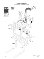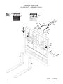
1
OPERATOR’S & PARTS
MANUAL
48” - 74” SIDE SHIFT
FORK CARRIAGE
SERIAL NUMBER: ___________________
MODEL NUMBER: ___________________
800-456-7100 I www.paladinlcg.com
Manual Number: 76826
Part Number: 76826
Rev. 2: January 28, 2010
503 Gay Street, Delhi, IA 52223, United States of America
M-2000
1-26-10-2
TABLE OF CONTENTS
FOREWORD ...............................................................................................................................2
PREFACE....................................................................................................................................3
SAFETY PRECAUTIONS ....................................................................................................... 4-8
SAFETY STATEMENTS .......................................................................................................................................4
GENERAL SAFETY PRECAUTIONS................................................................................................................4-6
EQUIPMENT SAFETY PRECAUTIONS ...........................................................................................................7-8
INSTALLATION AND OPERATION ...................................................................................... 9-12
ATTACHING AND DETACHING SIDE SHIFT FORK CARRIAGE ........................................................................9
OPERATING SIDE SHIFT FORK CARRIAGE .................................................................................................9-10
TROUBLESHOOTING ........................................................................................................................................ 11
MAINTENANCE AND SERVICE......................................................................................... 13-15
GENERAL INFORMATION...................................................................................................................................13
DAILY ..................................................................................................................................................................13
EVERY 40 HOURS .............................................................................................................................................13
CYLINDER SEAL REPLACEMENT ...............................................................................................................14-15
SPECIFICATIONS.....................................................................................................................16
BOLT TORQUE .........................................................................................................................17
STORAGE .................................................................................................................................18
LIMITED WARRANTY ..............................................................................................................19
PARTS
SIDE SHIFT FORK CARRIAGES
48” SIDE SHIFT FORK CARRIAGE ASSEMBLY #11324 ....................................................................22-23
48” SIDE SHIFT FORK CARRIAGE ASSEMBLY #12426 ...................................................................24-25
48” SIDE SHIFT FORK CARRIAGE ASSEMBLY #12633 ...................................................................26-27
48” SIDE SHIFT FORK CARRIAGE ASSEMBLY #12540 ...................................................................28-29
48” SIDE SHIFT FORK CARRIAGE ASSEMBLY #12644 ...................................................................30-31
48” SIDE SHIFT FORK CARRIAGE ASSEMBLY #12659 ...................................................................32-33
48” SIDE SHIFT FORK CARRIAGE ASSEMBLY #12966 ...................................................................34-35
60” SIDE SHIFT FORK CARRIAGE ASSEMBLY #12703 ...................................................................36-37
66” SIDE SHIFT FORK CARRIAGE ASSEMBLY #12319 ...................................................................38-39
74” SIDE SHIFT FORK CARRIAGE ASSEMBLY #11510 ....................................................................40-41
74” SIDE SHIFT FORK CARRIAGE ASSEMBLY #12965 ...................................................................42-43
CYLINDERS
CYLINDER ASSEMBLY #88920 ............................................................................................................44-45
CYLINDER ASSEMBLY #88928 ............................................................................................................46-47
76826
M-1994
7-30-08
1
FOREWORD
Although Bradco has various side shift fork carriages available, we are continually designing
new sizes and mountings. If your combination is not listed, please contact the factory. We have
extensive mounting information available to generate the product you need.
Below is a listing of the side shift fork carriages that are currently available. See the “Parts”
section of this manual for the assemblies “Shown”.
DESCRIPTION & MOUNT
ASSEMBLY #
CATERPILLAR
48” Side Shift Fork Carriage - CAT IT/TH 10,000 LB CAP 60MM SHAFT (Shown)
74” Side Shift Fork Carriage - CAT IT/TH 10,000 LB CAP 60MM SHAFT (Shown)
GEHL
66” Side Shift Fork Carriage - GEHL DYNACARRIER (Shown)
IR
48” Side Shift Fork Carriage - IR VR518/VR623 6,000 LB CAP 2” SHAFT (Shown)
JCB
48” Side Shift Fork Carriage - JCB 10,000 LB CAP 2 1/4 SHAFT (Shown)
48” Side Shift Fork Carriage - JCB 520 5,500 LB CAP ITA CLASS II (Shown)
48” Side Shift Fork Carriage - JCB 10,000 LB CAP, ITA CLASS III (Shown)
JLG
48” Side Shift Fork Carriage - JLG/GRADALL “C” SERIES (Shown)
74” Side Shift Fork Carriage - JLG/GRADALL “C” SERIES (Shown)
60” Side Shift
48” Side Shift
48” Side Shift
48” Side Shift
2
11324
11510
12319
12426
12633
12644
12659
12966
12965
MANITOU
Fork Carriage - MANITOU 10,000 LB CAP, ITA CLASS III
(Shown)
NEW HOLLAND
Fork Carriage - NH 10,000 LB CAP 2 1/4 SHAFT (Shown)
Fork Carriage - NH VERSATTACH 10,000 LB CAP, ITA CLASS II (Shown)
TEREX
Fork Carriage - TEREX TX51-19 TEREX HITCH
(Shown)
M-1999
12703
12633
12659
12540
1-28-10-2
76826
PREFACE
GENERAL COMMENTS
Congratulations on the purchase of your new attachment! This product was carefully
designed and manufactured to give you many years of dependable service. Only minor
maintenance, such as cleaning and lubricating, is required to keep it in top working condition. Be
sure to observe all maintenance procedures and safety precautions in this manual and on any
safety decals located on the product, and on any equipment on which the attachment is mounted.
Also, check load charts before operating the attachment.
This manual has been designed to help you do a better, safer job. Read this manual
carefully and become familiar with its contents.
WARNING! Never let anyone operate this unit without reading the “Safety Precautions”
and “Operating Instructions” sections of this manual.
Always choose hard, level ground to park the vehicle on, and set the brake
so the unit cannot roll.
Unless noted otherwise, right and left sides are determined from the operator’s control
position when facing the attachment.
NOTE: The illustrations and data used in this manual were current, according to the
information available to us at the time of printing. However, we reserve the right to
redesign and change the attachment as may be necessary, without notification.
BEFORE OPERATION
The primary responsibility for safety with this equipment falls to the operator. Make sure
the equipment is operated only by trained individuals who have read and understand this manual.
If there is any portion of this manual or function that you do not understand, contact your local
authorized dealer or the manufacturer.
SAFETY ALERT SYMBOL
This is the “Safety Alert Symbol” used by this industry. This symbol is used to warn
of possible injury. Be sure to read all warnings carefully. They are included for your
safety and for the safety of others working with you.
SERVICE
When servicing your product, remember to use only manufacturer replacement parts.
Substitute parts may not meet the standards required for safe, dependable operation.
To facilitate parts ordering, record the model and serial number of your unit in the space
provided on the cover of this manual. This information may be obtained from the identification
plate located on the product.
The parts department needs this information to ensure that you receive the correct parts for
your specific model.
M-934
76826
9-21-05-2
3
SAFETY STATEMENTS
THIS SYMBOL BY ITSELF OR WITH A WARNING WORD THROUGHOUT THIS MANUAL IS USED TO CALL YOUR ATTENTION TO INSTRUCTIONS INVOLVING YOUR
PERSONAL SAFETY OR THE SAFETY OF OTHERS. FAILURE TO FOLLOW THESE
INSTRUCTIONS CAN RESULT IN INJURY OR DEATH.
DANGER
THIS SIGNAL WORD IS USED WHERE SERIOUS INJURY OR DEATH
WILL RESULT IF THE INSTRUCTIONS ARE NOT FOLLOWED PROPERLY.
WARNING
THIS SIGNAL WORD IS USED WHERE SERIOUS INJURY OR DEATH
COULD RESULT IF THE INSTRUCTIONS ARE NOT FOLLOWED PROPERLY.
CAUTION
THIS SIGNAL WORD IS USED WHERE MINOR INJURY COULD RESULT IF
THE INSTRUCTIONS ARE NOT FOLLOWED PROPERLY.
NOTICE
NOTICE INDICATES A PROPERTY DAMAGE MESSAGE.
GENERAL SAFETY PRECAUTIONS
WARNING!
READ MANUAL PRIOR TO INSTALLATION
Improper installation, operation, or maintenance of this equipment could result in serious injury or death. Operators and maintenance personnel should read this manual,
as well as all manuals related to this equipment and the prime mover thoroughly
before beginning installation, operation, or maintenance. FOLLOW ALL SAFETY
INSTRUCTIONS IN THIS MANUAL AND THE PRIME MOVER’S MANUAL(S).
READ AND UNDERSTAND ALL SAFETY STATEMENTS
Read all safety decals and safety statements in all manuals prior to operating or
working on this equipment. Know and obey all OSHA regulations, local laws, and
other professional guidelines for your operation. Know and follow good work practices when assembling, maintaining, repairing, mounting, removing, or operating this
equipment.
KNOW YOUR EQUIPMENT
Know your equipment’s capabilities, dimensions, and operations before operating.
Visually inspect your equipment before you start, and never operate equipment that
is not in proper working order with all safety devices intact. Check all hardware to
ensure it is tight. Make certain that all locking pins, latches, and connection devices
are properly installed and secured. Remove and replace any damaged, fatigued, or
excessively worn parts. Make certain all safety decals are in place and are legible.
Keep decals clean, and replace them if they become worn or hard to read.
4
M-806
7-28-05-2
76826
GENERAL SAFETY PRECAUTIONS
WARNING!
PROTECT AGAINST FLYING DEBRIS
Always wear proper safety glasses, goggles, or a face shield when driving pins in or
out, or when any operation causes dust, flying debris, or any other hazardous material.
WARNING!
LOWER OR SUPPORT RAISED EQUIPMENT
Do not work under raised booms without supporting them. Do not use support material made of concrete blocks, logs, buckets, barrels, or any other material that could
suddenly collapse or shift positions. Make sure support material is solid, not decayed, warped, twisted, or tapered. Lower booms to ground level or on blocks. Lower
booms and attachments to the ground before leaving the cab or operator’s station.
WARNING!
USE CARE WITH HYDRAULIC FLUID PRESSURE
Hydraulic fluid under pressure can penetrate the skin and cause serious injury or
death. Hydraulic leaks under pressure may not be visible. Before connecting or disconnecting hydraulic hoses, read your prime mover’s operator’s manual for detailed
instructions on connecting and disconnecting hydraulic hoses or fittings.
•
•
•
Keep unprotected body parts, such as face, eyes, and arms as far away as
possible from a suspected leak. Flesh injected with hydraulic fluid may develop
gangrene or other permanent disabilities.
If injured by injected fluid, see a doctor at once. If your doctor is not familiar with
this type of injury, ask him or her to research it immediately to determine proper
treatment.
Wear safety glasses, protective clothing, and use a piece of cardboard or wood
when searching for hydraulic leaks. DO NOT USE YOUR HANDS! SEE ILLUSTRATION.
CARDBOARD
HYDRAULIC HOSE
OR FITTING
MAGNIFYING GLASS
76826
M-807 7-28-05-2
5
GENERAL SAFETY PRECAUTIONS
WARNING!
DO NOT MODIFY MACHINE OR ATTACHMENTS
Modifications may weaken the integrity of the attachment and may impair the function, safety, life, and performance of the attachment. When making repairs, use only
the manufacturer’s genuine parts, following authorized instructions. Other parts may
be substandard in fit and quality. Never modify any ROPS (Roll Over Protection
Structure) or FOPS (Falling Object Protective Structure) equipment or device. Any
modifications must be authorized in writing by the manufacturer.
WARNING!
SAFELY MAINTAIN AND REPAIR EQUIPMENT
•
•
•
•
•
Do not wear loose clothing or any accessories that can catch in moving parts. If
you have long hair, cover or secure it so that it does not become entangled in the
equipment.
Work on a level surface in a well-lit area.
Use properly grounded electrical outlets and tools.
Use the correct tools for the job at hand. Make sure they are in good condition for
the task required.
Wear the protective equipment specified by the tool manufacturer.
SAFELY OPERATE EQUIPMENT
Do not operate equipment until you are completely trained by a qualified operator
in how to use the controls, know its capabilities, dimensions, and all safety requirements. See your machine’s manual for these instructions.
• Keep all step plates, grab bars, pedals, and controls free of dirt, grease, debris,
and oil.
• Never allow anyone to be around the equipment when it is operating.
• Do not allow riders on the attachment or the prime mover.
• Do not operate the equipment from anywhere other than the correct operator’s
position.
• Never leave equipment unattended with the engine running, or with this attachment in a raised position.
• Do not alter or remove any safety feature from the prime mover or this attachment.
• Know your work site safety rules as well as traffic rules and flow. When in doubt
on any safety issue, contact your supervisor or safety coordinator for an explanation.
6
M-808 7-28-05-2
76826
EQUIPMENT SAFETY PRECAUTIONS
WARNING!
KNOW WHERE UTILITIES ARE
Observe overhead electrical and other utility lines. Be sure equipment will clear them.
When digging, call your local utilities for location of buried utility lines, gas, water, and
sewer, as well as any other hazard you may encounter.
OPERATING THE PRIME MOVER
Avoid steep hillside operation, which could cause the prime mover to overturn.
Consult your machine operator’s and safety manuals for maximum incline allowable.
When operating on a slope, keep the load low, and proceed with extreme caution.
Do not drive ACROSS a steep slope - drive straight up and down.
With a LOADED attachment - face the attachment and load uphill.
With an EMPTY attachment - face the attachment downhill.
OPERATING THE SIDE SHIFT FORK CARRIAGE
•
•
•
•
•
•
•
•
•
•
•
•
•
•
•
•
76826
Do not exceed the lifting capacity of your prime mover and attachment. Always
observe lift capacity limits listed in machine specifications or on load charts furnished with the prime mover.
Always space the forks correctly for the load. Loads can fall off incorrectly spaced
forks. Make sure the forks are completely under the load before lifting.
Be careful when handling large/loose objects. Lifting too high or rolling forks too
far back could result in these objects falling back on the operator. Unsecured
loads can cause vehicle tipover, which can result in serious injury or death.
Do not use the fork tines for prying or any purpose other than lifting.
Never stack loads on uneven ground. Loads stacked on uneven ground can
topple.
Never lift a load with one fork. A load lifted with one fork can slip off and cause
injury.
Secure loads properly. Unsecured loads can fall unexpectedly. When transporting
a load, keep the forks as close to the ground as possible.
Keep the lifting surface of the forks level at all times.
Do not handle round bales with fork lift tines.
Don’t obstruct your vision when traveling or working. Carry the forks low for maximum stability and visibility.
When using the side shift feature to pick up a load, be sure to return the forks and
load to the center position as soon as possible. Do NOT travel with loaded forks
shifted to the side.
If the carriage tilts or drifts due to oil leakage within the cylinder assembly, discontinue use until the problem has been corrected.
Reduce speed when driving over rough terrain, on a slope, or turning, to avoid
overturning the vehicle.
Never use the attachment for a work platform or personnel carrier.
An operator must not use drugs or alcohol, which can change his or her alertness
or coordination. An operator taking prescription or over-the-counter drugs should
seek medical advice on whether or not he or she can safely operate equipment.
Before exiting the prime mover, lower the attachment to the ground, apply the
brakes, turn off the prime mover’s engine, and remove the key.
M-1997
4-21-08
7
EQUIPMENT SAFETY PRECAUTIONS
EXPOSURE TO RESPIRABLE CRYSTALLINE SILICA DUST ALONG WITH
OTHER HAZARDOUS DUSTS MAY CAUSE SERIOUS OR FATAL RESPIRATORY DISEASE.
It is recommended to use dust suppression, dust collection, and if necessary,
personal protective equipment during the operation of any attachment that
may cause high levels of dust.
TRANSPORTING THE SIDE SHIFT FORK CARRIAGE
•
•
•
•
Travel only with the attachment in a safe transport position to prevent uncontrolled movement. Drive slowly over rough ground, and on slopes.
When driving on public roads, use safety lights, reflectors, Slow Moving Vehicle
signs, etc. to prevent accidents. Check local government regulations that may
affect you.
Do not drive close to ditches, excavations, etc., as a cave-in could result.
Do not smoke wen refueling the prime mover. Allow room in the fuel tank for expansion. Wipe up any spilled fuel, and secure cap tightly, when done.
MAINTAINING THE SIDE SHIFT FORK CARRIAGE
•
•
•
•
•
8
Before performing maintenance, lower the attachment to the ground, apply the
brakes, turn off the engine, and remove the key.
Never perform any work on the equipment unless you are authorized and
qualified to do so. Always read the operator’s and service manual(s) before any
repair is made. After completing maintenance or repair, check for correct functioning of the attachment. If not functioning properly, always attach a “DO NOT
OPERATE” tag to the machine until all problems are corrected.
Worn, damaged, or illegible safety decals must be replaced. New safety decals
can be ordered from the manufacturer.
Never make hydraulic repairs while the system is under pressure. Serious
personal injury or death could result.
Never work under a raised attachment.
M-1998
7-30-08
76826
INSTALLATION AND OPERATION
ATTACHING AND DETACHING SIDE SHIFT FORK CARRIAGE
Please see your vehicle operator’s manual for instructions on attaching and detaching your
equipment.
WARNING!
To prevent serious personal injury or death, only attach equipment that is
designed for your vehicle.
Specified lift capacities must not be exceeded, otherwise machine stability will
not be sufficient. Always observe lift capacity limits listed in machine specifications.
OPERATING SIDE SHIFT FORK CARRIAGE
•
•
Read all Safety Precautions before operating your new attachment.
For personal safety, lower the attachment to the ground, set the parking brake, shut
off engine, and remove key before getting off of your prime mover.
SPECIAL OPERATING CONSIDERATIONS:
SIDE SHIFT FORK CARRIAGE OPERATION
When using the side shift feature to pick up a load, be sure to return the forks and loads to the
center position as soon as possible. Do NOT travel with loaded forks shifted to the side.
CYLINDERS
IMPORTANT: If your hydraulically operated attachment tilts or starts to drift due to oil leakage
within the cylinder assembly, discontinue use until the problem has been
corrected.
76826
M-1996
4-17-08
9
INSTALLATION AND OPERATION
FORK CARRIAGE OPERATION
1. Approach the load in such a fashion that the weight will be centered between the fork
tines. The heaviest side should be closest to the fork frame, and not near the tips of the
fork tines.
2. Before lifting, make certain the fork tines are completely under the load, and level.
3. Lift the load slightly to make sure the load is stable. If the load appears unstable, lower
and reposition the tines to achieve full stability.
4. Raise the telehandler to the MINIMUM height required for the terrain.
5. During material handling:
• keep the fork tines level.
• stop and start the telehandler gradually.
• slow down before turning.
• avoid obstacles, bumps, or holes.
6. Check the load frequently to ensure stability.
WARNING! Never exceed the recommended lifting capacity of any approved fork tines
or the prime mover.
NOTE:
Fork tine capacities are pounds per pair at a 24” load center. (The
center of gravity of the allowable loads must be applied within
the first 24” of the fork tines when measured from the front face of
the vertical section of the fork tine out toward the tip of the
horizontal section of the fork tine.)
WARNING! EXPOSURE TO RESPIRABLE CRYSTALLINE SILICA DUST ALONG WITH
OTHER HAZARDOUS DUSTS MAY CAUSE SERIOUS OR FATAL RESPIRATORY DISEASE.
It is recommended to use dust suppression, dust collection and if necessary personal protective equipment during the operation of any attachment
that may cause high levels of dust!
IMPORTANT
Concrete and masonry products contain silica sand. Quartz, which is a form of silica
and the most common mineral in the earths crust, is associated with many types of
rock.
Some activities that silica dust may be present in the air include demolition, sweeping,
loading, sawing, hammering, drilling or planing of rock, concrete or masonry.
It is recommended to use dust suppression (such as water), dust collection (such as a
vacuum) along with personal protective equipment if necessary during the operation of
any attachment that may cause high levels of silica dust.
10
M-1931 4-4-08
76826
INSTALLATION AND OPERATION
TROUBLESHOOTING
ATTACHMENTS WITH HYDRAULICS
PROBLEM
POSSIBLE CAUSE
POSSIBLE REMEDY
Excessive oil temperature.
1. Hydraulic oil level too low.
• Refer to your vehicle operator’s manual.
2. Obstruction in hydraulic lines.
• Remove obstruction and replace, if
necessary.
3. Couplers not engaged correctly.
• Engage couplers.
4. Hydraulic system overloaded,
and system relief open.
• Reduce load.
1. Insufficient hydraulic flow from
the prime mover.
• Refer to your vehicle operator’s manual.
2. Cylinder rod bent.
• Visually inspect the cylinder for damage.
3. Cylinder seals damaged.
• Replace cylinder seals.
4. Obstruction in hydraulic lines.
• Remove obstruction and replace, if
necessary.
A Hydraulic cylinder
not operating.
SIDE SHIFT FORK CARRIAGES
PROBLEM
POSSIBLE CAUSE
POSSIBLE REMEDY
Hydraulic cylinder not operating - carriage does not shift.
1. Hydraulic hoses incorrectly
connected.
• Switch hoses on one cylinder.
2. Insufficient hydraulic flow from
the prime mover.
• Refer to your vehicle operator’s manual.
3. Cylinder rod bent.
• Visually inspect the cylinder for damage.
4. Cylinder seals damaged.
• Replace cylinder seals.
5. Obstruction in hydraulic lines.
• Remove obstruction and replace, if
necessary.
76826
M-1995 4-17-08
11
THIS PAGE
IS INTENTIONALLY
BLANK
12
76826
MAINTENANCE & SERVICE
GENERAL INFORMATION
Regular maintenance is the key to long equipment life and safe operation. Maintenance
requirements have been kept to an absolute minimum. However, it is very important that these
maintenance functions be performed as described in this section.
DAILY
•
Check all bolts and nuts for tightness.
•
Replace any missing bolts or nuts with approved replacement parts.
•
Check hydraulic system for hydraulic oil leaks. See procedure below.
•
Visually inspect the machine for worn parts or cracked welds, and repair
as necessary.
WARNING! Escaping fluid under pressure can have sufficient force to penetrate the
skin, causing serious personal injury. Fluid escaping from a very small
hole can be almost invisible. Use a piece of cardboard or wood, rather than
hands to search for suspected leaks.
Keep unprotected body parts, such as face, eyes, and arms as far away as
possible from a suspected leak. Flesh injected with hydraulic fluid may
develop gangrene or other permanent disabilities.
If injured by injected fluid, see a doctor at once. If your doctor is not
familiar with this type of injury, ask him or her to research it immediately to
determine proper treatment.
CARDBOARD
HYDRAULIC HOSE
OR FITTING
MAGNIFYING GLASS
IMPORTANT: When replacing parts, use only factory approved replacement parts. Manufacturer will not claim responsibility for use of unapproved parts or accessories and/or
other damages as a result of their use.
EVERY 40 HOURS
Lubrication is an important part of maintenance. It is recommended that all grease fittings
be lubricated after the intitial 8 hours of operation, and then after every 40 hours of use.
76826
M-852
5-27-05
13
MAINTENANCE AND SERVICE
CYLINDER SEAL REPLACEMENT
The following information is provided to assist you in the event you should need to repair or rebuild a hydraulic cylinder. When working on hydraulic cylinders, make sure that the work area and tools are clean and free
of dirt to prevent contamination of the hydraulic system and damage to the hydraulic cylinders. Always protect the
active part of the cylinder rod (the chrome section). Nicks or scratches on the surface of the rod could result in
cylinder failure. Clean all parts thoroughly with a cleaning solvent before reassembly.
DISASSEMBLY PROCEDURE
IMPORTANT: Do not contact the active surface of the cylinder rod with the vise. Damage to the rod could
result.
THREADED TYPE GLAND
Rotate the gland with a spanner wrench counterclockwise until the gland is free of the cylinder tube.
Pull the cylinder rod from the cylinder tube and inspect the piston and the bore of the cylinder tube for
deep scratches or galling. If damaged, the piston AND the cylinder tube must be replaced.
1. 2.
3.
Remove the hex nut, piston, flat washer or spacer tube (if so equipped), and gland from the cylinder rod. If
the cylinder rod is rusty, scratched, or bent, it must be replaced.
Remove and discard all the old seals.
4.
ASSEMBLY PROCEDURE
IMPORTANT: Replace all seals even if they do not appear to be damaged. Failure to replace all seals may
result in premature cylinder failure. NOTE: Seal kits will service most cylinders of similar bore size and
rod diameter.
1.
Install the cylinder rod seal in the gland first. Be careful not to damage the seal in the process, as it is
somewhat difficult to install.
NOTE: A special installation tool (Part #65349) is available to help with installing the seal. Simply fit the end of the
tool over the seal so that the large prong of the tool is on the outside of the seal, and the two smaller prongs on the
inside. The lip of the seal should be facing towards the tool. Rotate the handles on the tool around to wrap the seal
around the end of the tool.
10356
14
10-13-05
76826
MAINTENANCE AND SERVICE
Now insert the seal into the gland from the inner end. Position the seal in
its groove, and release and remove the tool. Press the seal into its seat
the rest of the way by hand.
2.
Install the new piston ring, rod wiper, O-rings and backup washers, if applicable, on the piston.
Be careful not to damage the seals. Caution must be used when installing
the piston ring. The ring must be stretched carefully over the piston with
a smooth, round, pointed tool.
3.
After installing the rod seal inside the gland, as shown in step #1, install
the external seal.
NOTE: Threaded glands may have been equipped with a separate O-ring and
backup washer system or a polypak (all in one) type seal. Current seal kits contain a polypak (all in one) type seal to replace the discarded seal types on ALL
THREADED GLANDS.
4.
Slide the gland onto the cylinder rod, being careful not to damage the rod
wiper. Then install the spacer, or flat washer (if so equipped), small o-ring,
piston, and hex nut onto the end of the cylinder rod.
5.
Secure the cylinder rod (mounting end) in a vise with a support at its center.
Torque the nut to the amount shown for the thread diameter of the cylinder
rod (see chart).
Thread Diameter
7/8"
*1"
1-1/8"
1-1/4"
1-3/8"
POUNDS - FEET
150-200
230-325
350-480
490-670
670-900
* 1" Thread Diameter WITH 1.25" Rod Diameter
Min. 230 ft. lbs.
Max. 250 ft. lbs.
IMPORTANT: Do not contact the active surface of the cylinder rod with the
vise. Damage to the rod could result.
6.
Apply a lubricant (such as Lubriplate #105) to the piston and teflon ring. Insert the cylinder rod assembly
into the cylinder tube.
IMPORTANT: Ensure that the piston ring fits squarely into the cylinder tube and piston groove, otherwise
the ring may be damaged and a leak will occur.
7.
Use a spanner wrench to rotate the gland clockwise into the cylinder. Continue to rotate the gland with the
spanner wrench until it is tight.
WARNING!
Cylinders serviced in the field are to be tested for leakage prior to the attachment being
placed in work. Failure to test rebuilt cylinders could result in damage to the cylinder and/or
the attachment, cause severe personal injury or even death.
10357
76826
10-13-05
15
SPECIFICATIONS
SIDE SHIFT FORK CARRIAGE SPECIFICATIONS
Overall Height (inches) Without Forks
Overall Width (inches)
Side Shift on Each Side of Center (inches)
Total Overall Side Shift Movement (inches)
Attachment Weight - Without Forks (lbs.)
Shipping Weight - Without Forks (lbs.)
Overall Height (inches) Without Forks
Overall Width (inches)
Side Shift on Each Side of Center (inches)
Total Overall Side Shift Movement (inches)
Attachment Weight - Without Forks (lbs.)
Shipping Weight - Without Forks (lbs.)
Overall Height (inches) Without Forks
Overall Width (inches)
Side Shift on Each Side of Center (inches)
Total Overall Side Shift Movement (inches)
Attachment Weight - Without Forks (lbs.)
Shipping Weight - Without Forks (lbs.)
Overall Height (inches) Without Forks
Overall Width (inches)
Side Shift on Each Side of Center (inches)
Total Overall Side Shift Movement (inches)
Attachment Weight - Without Forks (lbs.)
Shipping Weight - Without Forks (lbs.)
16
11324
11510
12319
40.50
49.00
4.00
8.00
640
690
45.25
75.50
4.00
8.00
826
876
39.38
67.78
4.00
8.00
897
947
12426
12540
12633
44.49
46.75
4.00
8.00
683
733
38.40
49.25
4.00
8.00
604
654
43.87
51.00
4.00
8.00
680
730
12644
12659
12703
49.80
49.51
4.00
8.00
590
640
44.83
51.00
4.00
8.00
963
1013
44.80
59.00
4.00
8.00
1052
1102
12966
12965
45.25
49.00
4.00
8.00
710
760
45.25
75.50
4.00
8.00
826
876
M-2001 4-21-08
76826
BOLT TORQUE SPECIFICATIONS
GENERAL TORQUE SPECIFICATION TABLES
Use the following charts when determining bolt torque specifications when special torques are not given.
Always use grade 5 or better when replacing bolts.
SAE BOLT TORQUE SPECIFICATIONS
NOTE: The following torque values are for use with extreme pressure lubricants, plating or hard washer
applications Increase torque 15% when using hardware that is unplated and either dry or lubricated with
engine oil.
SAE GRADE 5 TORQUE
Bolt Size
Pounds Feet
Newton-Meters
SAE GRADE 8 TORQUE
Pounds Feet
UNC
Newton-Meters
Inches
Millimeters
UNC
UNF
UNC
UNF
UNF
UNC
UNF
1/4
5/16
6.35
7.94
8
14
9
17
11
19
12
23
10
20
13
25
14
27
18
34
62
3/8
9.53
30
36
41
49
38
46
52
7/16
11.11
46
54
62
73
60
71
81
96
1/2
12.70
68
82
92
111
94
112
127
152
9/16
14.29
94
112
127
136
163
184
221
5/8
15.88
128
153
174
152
207
187
224
254
304
3/4
19.05
230
275
312
373
323
395
438
536
7/8
22.23
340
408
461
553
510
612
691
830
1
25.40
493
592
668
803
765
918
1037
1245
1-1/8
25.58
680
748
922
1014
1088
1224
1475
1660
1-1/4
31.75
952
1054
1291
1429
1547
1700
2097
2305
1-3/8
34.93
1241
1428
1683
1936
2023
2312
2743
3135
1-1/2
38.10
1649
1870
2236
2535
2686
3026
3642
4103
Bolt head identification marks as per
grade. NOTE: Manufacturing Marks Will
Vary
METRIC BOLT TORQUE SPECIFICATIONS
Bolt head identification marks as per grade.
NOTE: The following torque values are for use with metric
hardware that is unplated and either dry or lubricated with
engine oil. Reduce torque 15% when using hardware that has
extreme pressure lubricants, plating or hard washer
applications.
Size of Bolt
Grade No.
Pitch (mm)
Pounds Feet
Newton-Meters
Pitch (mm)
Pounds Feet
Newton-Meters
M6
5.6
8.8
10.9
1.0
3.6-5.8
5.8-.4
7.2-10
4.9-7.9
7.9-12.7
9.8-13.6
-
-
-
M8
5.6
8.8
10.9
1.25
7.2-14
17-22
20-26
9.8-19
23-29.8
27.1-35.2
1.0
12-17
19-27
22-31
16.3-23
25.7-36.6
29.8-42
M10
5.6
8.8
10.9
1.5
20-25
34-40
38-46
27.1-33.9
46.1-54.2
51.5-62.3
1.25
20-29
35-47
40-52
27.1-39.3
47.4-63.7
54.2-70.5
M12
5.6
8.8
10.9
1.75
28-34
51-59
57-66
37.9-46.1
69.1-79.9
77.2-89.4
1.25
31-41
56-68
62-75
42-55.6
75.9-92.1
84-101.6
M14
5.6
8.8
10.9
2.0
49-56
81-93
96-109
66.4-75.9
109.8-126
130.1-147.7
1.5
52-64
90-106
107-124
70.5-86.7
122-143.6
145-168
M16
5.6
8.8
10.9
2.0
67-77
116-130
129-145
90.8-104.3
157.2-176.2
174.8-196.5
1.5
69-83
120-138
140-158
93.5-112.5
162.6-187
189.7-214.1
M18
5.6
8.8
10.9
2.0
88-100
150-168
175-194
119.2-136
203.3-227.6
237.1-262.9
1.5
100-117
177-199
202-231
136-158.5
239.8-269.6
273.7-313
M20
5.6
8.8
10.9
2.5
108-130
186-205
213-249
146.3-176.2
252-277.8
288.6-337.4
1.5
132-150
206-242
246-289
178.9-203.3
279.1-327.9
333.3-391.6
76826
10360
3-20-08-3
17
STORAGE
GENERAL INFORMATION
The following storage procedure will help you to keep your attachment in top condition. It will
also help you get off to a good start the next time your equipment is needed. We therefore
strongly recommend that you take the extra time to follow these procedures whenever your
attachment will not be used for an extended period of time.
PREPARATION FOR STORAGE
1.
Clean the attachment thoroughly, removing all mud, dirt, and grease.
2.
Inspect for visible signs of wear, breakage, or damage. Order any parts required, and
make the necessary repairs, to avoid delays when starting next season.
3.
Tighten all loose nuts, capscrews, and hydraulic connections.
4.
Lubricate all grease fittings.
5.
Coat the exposed portions of the cylinder rods with grease.
6.
Connect the hydraulic couplers together to protect the hydraulic system from contaminates.
7.
Touch up all unpainted and exposed areas with paint, to prevent rust.
8.
Replace decals, if damaged or in unreadable condition.
9.
Store the attachment in a dry and protected place, with a cover, if possible. Leaving the
attachment outside will materially shorten its life.
REMOVING FROM STORAGE
1.
Remove all protective coverings.
2.
Check hydraulic hoses for deterioration, and replace if necessary.
18
M-1193
1-19-06
76826
Limited Warranty
Except for the Excluded Products as described below, all new products are warranted to be free from defects
in material and/or workmanship during the Warranty Period, in accordance with and subject to the terms and
conditions of this Limited Warranty.
1.
Excluded Products. The following products are excluded from this Limited Warranty:
(a) Any cable, part that engages with the ground (i.e. sprockets), digging chain, bearing, teeth, tamping
and/or demolition head, blade cutting edge, pilot bit, auger teeth and broom brush that either constitutes or is part
of a product.
(b) Any product, merchandise or component that, in the opinion of Paladin Light Construction1, has been
(i) misused; (ii) modified in any unauthorized manner; (iii) altered; (iv) damaged; (v) involved in an accident; or (vi)
repaired using parts not obtained through Paladin Light Construction.
2.
Warranty Period. The Limited Warranty is provided only to those defects that occur during the Warranty
Period, which is the period that begins on the first to occur of: (i) the date of initial purchase by an end-user, (ii) the
date the product is first leased or rented, or (iii) the date that is six (6) months after the date of shipment by Paladin
Light Construction as evidenced by the invoiced shipment date (the “Commencement Date”) and ends on the date
that is twelve (12) months after the Commencement Date.
3.
Terms and Conditions of Limited Warranty. The following terms and conditions apply to the Limited Warranty
hereby provided:
(a)
the product.
Option to Repair or Replace. Paladin Light Construction shall have the option to repair or replace
(b)
Timely Repair and Notice. In order to obtain the Limited Warranty, (i) the product must be repaired
within thirty (30) days from the date of failure, and (ii) a claim under the warranty must be submitted to Paladin Light
Construction in writing within thirty (30) days from the date of repair.
(c)
Return of Defective Part or Product. If requested by Paladin Light Construction, the alleged
defective part or product shall be shipped to Paladin Light Construction at its manufacturing facility or other location
specified by Paladin Light Construction, with freight PRE-PAID by the claimant, to allow Paladin Light Construction
to inspect the part or product.
Claims that fail to comply with any of the above terms and conditions shall be denied.
LIMITATIONS AND EXCLUSIONS.
THIS LIMITED WARRANTY IS IN LIEU OF ALL OTHER WARRANTIES, EXPRESS OR IMPLIED, INCLUDING
WITHOUT LIMITATION THE WARRANTIES OF MERCHANTABILITY, FITNESS FOR A PARTICULAR PURPOSE
AND ANY WARRANTY BASED ON A COURSE OF DEALING OR USAGE OF TRADE.
IN NO EVENT SHALL PALADIN LIGHT CONSTRUCTION BE LIABLE FOR CONSEQUENTIAL OR SPECIAL
DAMAGES.
IN NO EVENT SHALL PALADIN LIGHT CONSTRUCTION BE LIABLE FOR ANY LOSS OR CLAIM IN AN
AMOUNT IN EXCESS OF THE PURCHASE PRICE, OR, AT THE OPTION OF PALADIN LIGHT CONSTRUCTION,
THE REPAIR OR REPLACEMENT, OF THE PARTICULAR PRODUCT ON WHICH ANY CLAIM OF LOSS OR
DAMAGE IS BASED. THIS LIMITATION OF LIABILITY APPLIES IRRESPECTIVE OF WHETHER THE CLAIM
IS BASED ON BREACH OF CONTRACT, BREACH OF WARRANTY, NEGLIGENCE OR OTHER CAUSE AND
WHETHER THE ALLEGED DEFECT IS DISCOVERABLE OR LATENT.
Attachment Technologies Inc., a subsidiary of Paladin Brands Holding, Inc. (PBHI) is referred to herein as Paladin Light
Construction.
February 10, 2010
1
76826
19
THIS PAGE
IS INTENTIONALLY
BLANK
20
76826
PARTS
The following section contains detailed diagrams and parts lists which include your
attachment. Please use these diagrams and parts lists to locate replacement parts, prior to
contacting the parts department.
When servicing your attachment, remember to use only original manufacturer replacement parts. Substitute parts may not meet the standards required for safe, dependable operation.
To facilitate parts ordering, have the model and serial number of your product ready, to
ensure that you receive the correct parts for your specific attachment.
The model and serial number for your attachment should be recorded in the space
provided on the cover of this manual. This information may be obtained from the serial number
identification plate located on your attachment. See the parts diagram for your attachment
for the location.
NOTE: Most daily and emergency orders received by 2:00 P.M. will be shipped the same
day received, with “Emergency-Machine-Down” orders receiving first priority.
PARTS DEPARTMENT
(734) 996-9116
(800) 456-7100
We Encourage Fax Orders
(734) 996-9014
76826
M-1127
1-26-10-3
21
FORK CARRIAGE
48” SIDE SHIFT - ASSEMBLY #11324
1
3
4
25
26
MADE IN U.S.A.
24
5
3
2
4
5
27
8
12
7
27
21
19
22
11
8
23
6
9
29
12
26
10
28
24
15
25
13
18
20
16
15
17
14
FORK
FORK
22
M-1666
1-28-10-2
76826
FORK CARRIAGE
48” SIDE SHIFT - ASSEMBLY #11324
ITEM
1
2
3
4
5
QTY.
1
1
2
2
2
PART NO.
22519
22518
30201
37893
3297
6
7
8
9
10
1
1
2
1
1
37838
37492
3434
88920
14071
Hose .38” X 28” 6FJX-6FJX
Hose .38” X 40” 6FJX-6FJX
90° Elbow, 6MBo-6MJ
Cylinder Assembly
Pin, 1.00” x 3.31”
11
12
13
14
15
1
2
2
1
1
6
6
100770
10023
1513
32547
32470
1090
1505
Pin, 1.00” x 4.00”
.31” UNF x 1.00” Hex Capscrew
.31” Flat Washer
Right Pin Retainer
Left Pin Retainer
.50” UNC x 1.50” Hex Capscrew
.50” Lock Washer
16
17
18
19
20
1
1
1
1
1
32493
14262
-----
32468
32469
Side Shift Pin, 2.00” x 47.75”
Fork Pin, 60MM x 48.50”
Serial Number Identification Tag Location
Rear Frame
Front Frame
21
22
23
24
25
1
1
1
2
1
1
81358
10023
1513
Varies
40151
4338
Hose Clamp
.31” UNF x 1.00” Hex Capscrew
.31” Flat Washer
Logo
High Pressure Warning Decal
Made in USA Decal
26
27
28
29
2
2
2
4
4
40149
6133
14228
10012
1507
Pinch Point Danger Decal
Grease Zerk
Stop Block
.75" UNC x 2.25" Hex Capscrew, Grade 8
.75" Lock Washer
DESCRIPTION
Male Quick Coupler
Female Quick Coupler
Straight Connector, 12MBo-6MJ
Hose .38” X 40” 6FJX-6FJX90°
Bulkhead Straight Connector, 6MJ-6MJ
*CONTACT YOUR DEALER FOR TINES AVAILABLE FOR YOUR ATTACHMENT.
76826
M-1667
1-28-10-2
23
FORK CARRIAGE
48” SIDE SHIFT - ASSEMBLY #12426
3
1
4
13
3
5
9
7
16
11
MADE IN USA
2
4
10
6
10
11 8
17
12
13
14
20
18
20
17
16
19
15
18
21
20
22
20
23
19
FORK
FORK
24
M-1974
1-28-10-2
76826
FORK CARRIAGE
48” SIDE SHIFT - ASSEMBLY #12426
QTY.
PART NO.
1
2
3
4
5
1
1
2
2
1
22518
22519
30201
14397
3434
Female Quick Coupler
Male Quick Coupler
Straight Connector, 12MBo-6MJ
Hose .38" X 69" 6FJX-6FJX
90° Elbow, 6MBo-6MJ
6
7
8
9
10
1
1
1
1
2
2
2
14067
88928
14071
14070
1293
1503
1514
90° Elbow, W/.027 Orifice, 6MBo-6MJ
Cylinder Assembly
Pin, 1.00" x 3.31"
Pin, 1.00" x 4.72"
.38" UNF x 1.00" Hex Capscrew
.38" Lock Washer
.38" Flat Washer
11
12
13
14
15
2
2
2
1
1
9371
Varies
40149
16842
-----
Grease Zerk
Logo
Decal, Pinch Point
Rear Frame
Serial Number Identification Tag Location
16
17
18
19
20
1
1
1
1
8
8
4338
40151
16851
14002
1339
1505
Made in USA Decal
High Pressure Warning Decal
Side Shift Pin Retainer
Fork Pin Retainer
.50" UNF x 1.25" Hex Capscrew
.50" Lock Washer
21
22
23
1
1
1
16841
16846
15244
Front Frame
Side Shift Pin, 2.00” x 48.25”
Fork Pin, 2.00" x 49.00"
ITEM
DESCRIPTION
*CONTACT YOUR DEALER FOR TINES AVAILABLE FOR YOUR ATTACHMENT.
76826
M-1975
1-28-10-2
25
FORK CARRIAGE
48” SIDE SHIFT - ASSEMBLY #12633
1
3
4
7
5
19
5
6
7
8
6
7
15
8
12
14
11
18
7
13
14
2
10
20
MADE IN USA
16
9
15
17
21
18
20
19
25
22
26
23
24
FORK
FORK
26
M-1668
1-28-10-2
76826
FORK CARRIAGE
48” SIDE SHIFT - ASSEMBLY #12633
ITEM
QTY.
PART NO.
DESCRIPTION
1
2
3
4
5
1
1
1
1
2
32548
84928
32549
84923
3269
Dust Cover
Female Quick Coupler
Dust Cover
Male Quick Coupler
Straight Connector, 8MBo-6MJ
6
7
8
9
10
2
2
2
1
1
37887
3297
37862
3434
88928
Hose .38" X 64" 6FJX-6FJX
Bulkhead Connector, 6MJ-6MJ
Hose .38" X 23.25" 6FJX-6FJX90°
90° Elbow, 6MBo-6MJ
Cylinder Assembly
11
12
13
14
15
1
1
1
2
2
2
2
14067
31990
14070
1293
1503
1514
9371
90° Elbow, W/.027 Orifice, 6MBo-6MJ
Pin, 1.00" x 4.50"
Pin, 1.00" x 4.72"
.38" UNF x 1.00" Hex Capscrew
.38" Lock Washer
.38" Flat Washer
Grease Zerk
16
17
18
19
20
1
2
2
1
1
33530
Varies
40149
40151
4338
Rear Frame
Logo
Decal, Pinch Point
High Pressure Warning Decal
Made in USA Decal
21
22
23
24
25
1
1
3
3
3
1
1
-----
33554
1339
1505
1516
33531
33549
Serial Number Identification Tag Location
Pin Retainer
.50" UNF x 1.25" Hex Capscrew
.50" Lock Washer
.50" Flat Washer
Front Frame
Side Shift Pin, 2.00” x 53.00”
26
1
33550
Fork Pin, 2.25" x 53.50"
*CONTACT YOUR DEALER FOR TINES AVAILABLE FOR YOUR ATTACHMENT.
76826
M-1669
1-28-10-2
27
FORK CARRIAGE
48” SIDE SHIFT - ASSEMBLY #12540
1
3
4
21
20
MADE IN U.S.A.
3
2
4
23
22
5
11
18
10
5
23
6
6
7
22
8
7
14
20
12
9
11
21
17
19
14
15
16
13
FORK
FORK
28
M-1984
7-30-08
76826
FORK CARRIAGE
48” SIDE SHIFT - ASSEMBLY #12540
ITEM
1
2
3
4
5
QTY.
1
1
2
2
2
PART NO.
22519
22518
30201
35424
3297
6
7
8
9
10
2
2
1
1
1
38036
3434
88920
14071
31990
Hose .38” X 15” 6FJX-6FJX
90° Elbow, 6MBo-6MJ
Cylinder Assembly
Pin, 1.00” x 3.31”
Pin, 1.00” x 4.50”
11
15
2
2
1
1
6
6
1
10023
1513
32547
32470
1090
1505
32493
.31” UNF x 1.00” Hex Capscrew
.31” Flat Washer
Right Pin Retainer
Left Pin Retainer
.50” UNC x 1.50” Hex Capscrew
.50” Lock Washer
Side Shift Pin, 2.00” x 47.75”
16
17
18
19
1
1
1
1
104880
----19039
19040
Fork Pin, 2.25” x 48.38”
Serial Number Identification Tag Location
Rear Frame
Front Frame
20
21
22
23
1
1
2
2
40151
4338
40149
6133
High Pressure Warning Decal
Made in USA Decal
Pinch Point Danger Decal
Grease Zerk
12
13
14
DESCRIPTION
Male Quick Coupler
Female Quick Coupler
Straight Connector, 12MBo-6MJ
Hose .38” X 76” 6FJX-6FJX
Bulkhead Straight Connector, 6MJ-6MJ
*CONTACT YOUR DEALER FOR TINES AVAILABLE FOR YOUR ATTACHMENT.
76826
M-1985
7-30-08
29
FORK CARRIAGE
48” SIDE SHIFT - ASSEMBLY #12644
19
20
MADE IN U.S.A.
23
10
22
6
5
1
2
6
8
23
19
5
12
3
4
7
18
9
15
11
17
20
21
16
13
14
FORK
FORK
M-1679
30
1-28-10-2
76826
FORK CARRIAGE
48” SIDE SHIFT - ASSEMBLY #12644
QTY.
2
3
4
5
1
1
1
1
2
PART NO.
32549
84923
32548
84928
3269
Male Dust Cover
Male Quick Coupler
Female Dust Cover
Female Quick Coupler
Straight Connector, 8MBo-6MJ
6
7
8
9
10
2
1
1
1
1
37839
3434
30259
88928
14071
Hose .38” X 50” 6FJX-6FJX
90° Elbow, 6MBo-6MJ
90° Elbow, 6MBo-6MJ With 0.60” Orifice
Cylinder Assembly
Pin, 1.00” x 3.31”
11
12
13
14
15
1
2
2
2
1
2
2
1
14070
1043
1514
1503
14606
1089
1505
24506
Pin, 1.00” x 4.72”
.38” UNC x 1.00” Hex Capscrew
.38” Flat Washer
.38” Lock Washer
Pin Retainer
.50” UNC x 1.25” Hex Capscrew
.50” Lock Washer
Side Shift Pin, 2.00” x 49.50”
16
17
18
19
20
1
2
1
1
1
24495
9371
-----
4338
40151
Front Frame
Grease Zerk
Serial Number Identification Tag Location
Made in USA Decal
High Pressure Warning Decal
21
22
23
1
2
2
24496
Varies
40149
Rear Frame
Logo
Pinch Point Danger Decal
ITEM
1
DESCRIPTION
*CONTACT YOUR DEALER FOR TINES AVAILABLE FOR YOUR ATTACHMENT.
76826
M-1680
1-28-10-2
31
FORK CARRIAGE
48” SIDE SHIFT - ASSEMBLY #12659
5
3
4
1
6
15
5
2
6
19
19
20
18
15
21
7
13
14
8
10
7
MADE IN USA
16
17
8
18
12 14
22
21
11
9
23
26
24
25
FORK
FORK
32
M-1990
1-28-10-2
76826
FORK CARRIAGE
48” SIDE SHIFT - ASSEMBLY #12659
ITEM
QTY.
PART NO.
DESCRIPTION
1
2
3
4
5
1
1
1
1
2
32548
84928
32549
84923
3269
Dust Cover
Female Quick Coupler
Dust Cover
Male Quick Coupler
Straight Connector, 8MBo-6MJ
6
7
8
9
10
2
2
2
1
1
37887
3297
37862
3434
88928
Hose .38" X 64" 6FJX-6FJX
Bulkhead Connector, 6MJ-6MJ
Hose .38" X 23.25" 6FJX-6FJX90°
90° Elbow, 6MBo-6MJ
Cylinder Assembly
11
12
13
14
15
1
1
1
2
2
2
2
14067
31990
12054
1293
1503
1514
9371
90° Elbow, W/.027 Orifice, 6MBo-6MJ
Pin, 1.00" x 4.50"
Pin, 1.00" x 3.75"
.38" UNF x 1.00" Hex Capscrew
.38" Lock Washer
.38" Flat Washer
Grease Zerk
16
17
18
19
20
1
2
2
1
1
33530
Varies
40149
40151
-----
Rear Frame
Logo
Pinch Point Decal
High Pressure Warning Decal
Serial Number Identification Tag Location
21
22
23
24
25
1
1
1
2
2
2
1
4338
33549
33541
1339
1505
1516
100974
Made in USA Decal
Side Shift Pin, 2.00” x 53.00”
Pin Retainer
.50" UNF x 1.25" Hex Capscrew
.50" Lock Washer
.50" Flat Washer
Front Frame
26
1
1
1
1089
86149
1228
.50" UNC x 1.25" Hex Capscrew
Spacer
.50" UNC Hex Nut
*CONTACT YOUR DEALER FOR TINES AVAILABLE FOR YOUR ATTACHMENT.
76826
M-1991
1-28-10-2
33
FORK CARRIAGE
48” SIDE SHIFT - ASSEMBLY #12966
21
20
2
5
1
6
3
MADE IN U.S.A.
5
11
10
4
6
8
23
24
11
7 7
9
24
18
22
23
14
20
21
12
17
19
15
16
14
FORK
13
FORK
34
M-1986
1-28-10-2
76826
FORK CARRIAGE
48” SIDE SHIFT - ASSEMBLY #12966
ITEM
1
2
3
4
5
QTY.
1
1
1
1
2
PART NO.
51753
15109
51754
15110
3125
DESCRIPTION
Dust Cap
Male Quick Coupler
Dust Plug
Female Quick Coupler
Straight Connector, 6MJ-8MP
6
7
8
9
10
2
2
1
1
1
37839
3434
88920
14071
100770
Hose .38” X 50” 6FJX-6FJX
90° Elbow, 6MBo-6MJ
Cylinder Assembly
Pin, 1.00” x 3.31”
Pin, 1.00” x 4.00”
11
12
13
14
15
2
2
2
1
1
6
6
1
10023
1502
1513
32547
32470
1090
1505
32493
.31” UNF x 1.00” Hex Capscrew
.31” Lock Washer
.31” Flat Washer
Right Pin Retainer
Left Pin Retainer
.50” UNC x 1.50” Hex Capscrew
.50” Lock Washer
Side Shift Pin, 2.00” x 47.75”
16
17
18
19
20
1
1
1
1
1
14262
-----
107318
32469
40151
Fork Pin, 60MM x 48.50”
Serial Number Identification Tag Location
Rear Frame
Front Frame
High Pressure Warning Decal
21
22
23
24
1
2
2
2
4338
Varies
40149
6133
Made in USA Decal
Logo
Pinch Point Danger Decal
Grease Zerk
*CONTACT YOUR DEALER FOR TINES AVAILABLE FOR YOUR ATTACHMENT.
76826
M-1987
1-28-10-2
35
FORK CARRIAGE
60” SIDE SHIFT - ASSEMBLY #12703
17
1
1
2
11
12
2
MADE IN USA
3
3
4
4
5
18
16
5
6
6
5
5
19
13
21
12
8
9
13
10
7
20
18
22
15
14
24
16
17
23
FORK
FORK
36
M-1144
1-28-10-3
76826
FORK CARRIAGE
60” SIDE SHIFT - ASSEMBLY #12703
ITEM
QTY.
PART NO.
DESCRIPTION
1
2
3
4
5
2
2
2
2
2
32548
84928
3269
37887
3297
Dust Cover
Female Quick Coupler
Straight Connector, 8MBo-6MJ
Hose .38" X 64" 6FJX-6FJX
Bulkhead Connector, 6MJ-6MJ
6
7
8
9
10
2
1
1
1
1
37862
3434
88928
14067
12054
Hose .38" X 23.25" 6FJX-6FJX90°
90° Elbow, 6MBo-6MJ
Cylinder Assembly
90° Elbow, W/.027 Orifice, 6MBo-6MJ
Pin, 1.00" x 3.75"
11
12
13
14
15
1
2
2
2
2
1
2
31990
1293
1503
1514
9371
102014
Varies
Pin, 1.00" x 4.50"
.38" UNF x 1.00" Hex Capscrew
.38" Lock Washer
.38" Flat Washer
Grease Zerk
Rear Frame
Logo
16
17
18
19
20
2
1
1
1
1
40149
40151
4338
-----
33541
Decal, Pinch Point
High Pressure Warning Decal
Made in USA Decal
Serial Number Identification Tag Location
Pin Retainer
21
22
23
24
2
2
2
1
1
1
1
1
1339
1505
1516
102015
1089
86149
1228
111597
.50" UNF x 1.25" Hex Capscrew
.50" Lock Washer
.50" Flat Washer
Front Frame
.50" UNC x 1.25" Hex Capscrew
Spacer
.50" UNC Hex Nut
Fork Pin, 2.00" x 61.00"
*CONTACT YOUR DEALER FOR TINES AVAILABLE FOR YOUR ATTACHMENT.
76826
M-1145
1-28-10-3
37
FORK CARRIAGE
66” SIDE SHIFT - ASSEMBLY #12319
3
1
4
2
MADE IN USA
14
8
5
3
9
9
5
12
4
7
6
13
10
11
12
13
14
15
18
20
21
16
17
19
FORK
17
FORK
38
M-1992
1-28-10-2
76826
FORK CARRIAGE
66” SIDE SHIFT - ASSEMBLY #12319
QTY.
PART NO.
1
2
3
4
5
1
1
2
2
2
22518
22519
30201
37886
3434
Female Quick Coupler
Male Quick Coupler
Straight Connector, 12MBo-6MJ
Hose .38" X 60" 6FJX-6FJX
90° Elbow, 6MBo-6MJ
6
7
8
9
10
1
1
1
2
2
2
1
88928
14071
14070
1293
1503
1514
33020
Cylinder Assembly
Pin, 1.00" x 3.31"
Pin, 1.00" x 4.72"
.38" UNF x 1.00" Hex Capscrew
.38" Lock Washer
.38" Flat Washer
Rear Frame
11
12
13
14
15
2
2
1
1
1
Varies
40149
40151
4338
-----
Logo
Decal, Pinch Point
High Pressure Warning Decal
Made in USA Decal
Serial Number Identification Tag Location
16
17
18
19
20
1
4
4
4
1
1
1
14002
1339
1505
1516
33011
14606
33027
Fork Pin Retainer
.50" UNF x 1.25" Hex Capscrew
.50" Lock Washer
.50" Flat Washer
Front Frame
Side Shift Pin Retainer
Side Shift Pin, 2.00" x 66.00"
21
1
33199
Fork Pin, 2.00" x 66.75"
ITEM
DESCRIPTION
*CONTACT YOUR DEALER FOR TINES AVAILABLE FOR YOUR ATTACHMENT.
76826
M-1993
1-28-10-2
39
FORK CARRIAGE
74” SIDE SHIFT - ASSEMBLY #11510
3
25
24
1
4
MADE IN U.S.A.
5
3
26
2
4
5
27
8
12
11
27
7
19
21 22
8
23
6
9
29
12
24
10
26
28
15
13
16
25
18
20
17
15
FORK
14
FORK
40
M-1982
1-28-10-2
76826
FORK CARRIAGE
74” SIDE SHIFT - ASSEMBLY #11510
ITEM
1
2
3
4
5
QTY.
1
1
2
2
2
PART NO.
22519
22518
30201
37893
3297
6
7
8
9
10
1
1
2
1
1
37838
37492
3434
88920
14071
Hose .38” X 28” 6FJX-6FJX
Hose .38” X 40” 6FJX-6FJX
90° Elbow, 6MBo-6MJ
Cylinder Assembly
Pin, 1.00” x 3.31”
11
12
13
14
15
1
2
2
1
1
6
6
100770
10023
1513
32547
32470
1090
1505
Pin, 1.00” x 4.00”
.31” UNF x 1.00” Hex Capscrew
.31” Flat Washer
Right Pin Retainer
Left Pin Retainer
.50” UNC x 1.50” Hex Capscrew
.50” Lock Washer
16
17
18
19
20
1
1
1
1
1
14780
14602
-----
32468
15007
Side Shift Pin, 2.00” x 74.25”
Fork Pin, 60MM x 74.75”
Serial Number Identification Tag Location
Rear Frame
Front Frame
21
22
23
24
25
1
1
1
2
1
1
81358
10023
1513
Varies
40151
4338
Hose Clamp
.31” UNF x 1.00” Hex Capscrew
.31” Flat Washer
Logo
High Pressure Warning Decal
Made in USA Decal
26
27
28
29
2
2
2
4
4
40149
6133
14228
10012
1507
Pinch Point Danger Decal
Grease Zerk
Stop Block
.75" UNC x 2.25" Hex Capscrew, Grade 8
.75" Lock Washer
DESCRIPTION
Male Quick Coupler
Female Quick Coupler
Straight Connector, 12MBo-6MJ
Hose .38” X 40” 6FJX-6FJX90°
Bulkhead Straight Connector, 6MJ-6MJ
*CONTACT YOUR DEALER FOR TINES AVAILABLE FOR YOUR ATTACHMENT.
76826
M-1983
1-28-10-2
41
FORK CARRIAGE
74” SIDE SHIFT - ASSEMBLY #12965
20
2
5
21
1
6
3
MADE IN U.S.A.
5
11
10
23
4
6
8
24
11
7
7
24
9
18
22
14
23
20
12
15
21
17
19
16
14
FORK
13
FORK
42
M-1988
1-28-10-2
76826
FORK CARRIAGE
74” SIDE SHIFT - ASSEMBLY #12965
ITEM
1
2
3
4
5
QTY.
1
1
1
1
2
PART NO.
51753
15109
51754
15110
3125
DESCRIPTION
Dust Cap
Male Quick Coupler
Dust Plug
Female Quick Coupler
Straight Connector, 6MJ-8MP
6
7
8
9
10
2
2
1
1
1
37839
3434
88920
14071
100770
Hose .38” X 50” 6FJX-6FJX
90° Elbow, 6MBo-6MJ
Cylinder Assembly
Pin, 1.00” x 3.31”
Pin, 1.00” x 4.00”
11
12
13
14
15
2
2
2
1
1
6
6
1
10023
1502
1513
32547
32470
1090
1505
14780
.31” UNF x 1.00” Hex Capscrew
.31” Lock Washer
.31” Flat Washer
Right Pin Retainer
Left Pin Retainer
.50” UNC x 1.50” Hex Capscrew
.50” Lock Washer
Side Shift Pin, 2.00” x 74.25”
16
17
18
19
20
1
1
1
1
1
14602
-----
107318
15007
40151
Fork Pin, 60MM x 74.75”
Serial Number Identification Tag Location
Rear Frame
Front Frame
High Pressure Warning Decal
21
22
23
24
1
2
2
2
4338
Varies
40149
6133
Made in USA Decal
Logo
Pinch Point Danger Decal
Grease Zerk
*CONTACT YOUR DEALER FOR TINES AVAILABLE FOR YOUR ATTACHMENT.
76826
M-1989
1-28-10-2
43
CYLINDER ASSEMBLY
ASSEMBLY #88920
2
17
2
1
3
4
5
6
7
8
9
10
11
12
13
14
17
15
16
44
M-664
10-15-07-2
76826
CYLINDER ASSEMBLY
ASSEMBLY #88920
ITEM
QTY.
PART NO.
DESCRIPTION
1
2
3
4
5
1
2
1
1
1
89112
88919
1483
4644*
4645*
Cylinder Tube, With Valve
Bronze Bushing
Hex Nut
Piston Ring
O-Ring
6
7
8
9
10
1
1
1
1
1
50252
4641*
5421
4509*
4510*
Piston
O-Ring
Washer
O-Ring
Back-Up Washer
11
12
13
14
15
1
1
1
1
1
45250*
77458
45219*
45389*
88915
O-Ring
Cylinder Gland
Poly-Pak Seal
Rod Wiper
Piston Rod
16
17
1
1
88918
6616
Bronze Bushing
Grease Zerk
NOTE: Seal Kit #45617 includes all parts marked with an asterisk (*). Parts are not sold
separately.
76826
M-665
10-15-07-2
45
CYLINDER ASSEMBLY
ASSEMBLY #88928
2
17
1
4
2
3
5
6
8
7
9
10
11
12
13
14
17
15
16
46
M-1029
9-13-05
76826
CYLINDER ASSEMBLY
ASSEMBLY #88928
ITEM
QTY.
PART NO.
DESCRIPTION
1
2
3
4
5
1
2
1
1
1
88926
88919
1483
4644*
4645*
Cylinder Tube
Bronze Bushing
Hex Nut
Piston Ring
O-Ring
6
7
8
9
10
1
1
1
1
1
50252
4641*
5421
4509*
4510*
Piston
O-Ring
Washer
O-Ring
Back-Up Washer
11
12
13
14
15
1
1
1
1
1
45250*
77458
45219*
45389*
88927
O-Ring
Cylinder Gland
Poly-Pak Seal
Rod Wiper
Cylinder Rod
16
17
1
2
88918
6616
Bronze Bushing
Grease Zerk
NOTE: Seal Kit #45617 includes all parts marked with an asterisk (*). Parts are not sold
separately.
76826
M-1030
9-15-05
47
503 Gay Street
Delhi, IA 52223
(563) 922-2981
(800) 456-7100
www.paladinlcg.com
48
M-1360
1-26-10-2
76826