1
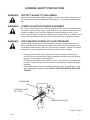
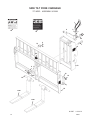
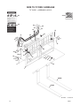
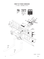
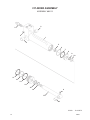
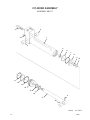
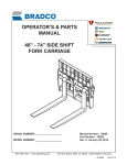
OPERATOR’S & PARTS
MANUAL
72” & 74” SIDE TILT
FORK CARRIAGE
SERIAL NUMBER: ___________________
MODEL NUMBER: ___________________
800-456-7100 I www.paladinlcg.com
Manual Number: 76828
Part Number: 76828
Rev. 2: January 27, 2010
503 Gay Street, Delhi, IA 52223, United States of America
M-1581
1-26-10-2
TABLE OF CONTENTS
PREFACE................................................................................................................................................. 3
SAFETY PRECAUTIONS ..................................................................................................................... 4-7
SAFETY STATEMENTS .......................................................................................................................................4
GENERAL SAFETY PRECAUTIONS................................................................................................................5-6
EQUIPMENT SAFETY PRECAUTIONS ..............................................................................................................7
INSTALLATION AND OPERATION ......................................................................................................... 8
ATTACHING AND DETACHING EQUIPMENT ......................................................................................................8
OPERATING EQUIPMENT ...................................................................................................................................8
SIDE TILT FORK CARRIAGE ..............................................................................................................................8
MAINTENANCE AND SERVICE......................................................................................................... 9-11
GENERAL INFORMATION.....................................................................................................................................9
DAILY ....................................................................................................................................................................9
EVERY 40 HOURS ...............................................................................................................................................9
CYLINDER SEAL REPLACEMENT ...............................................................................................................10-11
STORAGE .............................................................................................................................................. 12
LIMITED WARRANTY ........................................................................................................................... 13
PARTS
SIDE TILT FORK CARRIAGES
72” SIDE TILT FORK CARRIAGE ASSEMBLY #11492 ..........................................................................16-17
72” SIDE TILT FORK CARRIAGE ASSEMBLY #11709 .........................................................................18-19
72” SIDE TILT FORK CARRIAGE ASSEMBLY #12288 .........................................................................20-21
72” SIDE TILT FORK CARRIAGE ASSEMBLY #12515 ..........................................................................22-23
72” SIDE TILT FORK CARRIAGE ASSEMBLY #12784 ..........................................................................24-25
72” SIDE TILT FORK CARRIAGE ASSEMBLY #12789 ..........................................................................26-27
74” SIDE TILT FORK CARRIAGE ASSEMBLY #12427 ..........................................................................28-31
CYLINDERS
CYLINDER ASSEMBLY #89113 ............................................................................................................32-33
CYLINDER ASSEMBLY #89117 ............................................................................................................34-35
M-1584
76828
1-6-08
1
FOREWORD
Although Bradco has various side tilt fork carriages available, we are continually designing
new sizes and mountings. If your combination is not listed, please contact the factory. We have
extensive mounting information available to generate the product you need.
Below is a listing of the fork positioners that are currently available in 72” and 74” widths. See
the “Parts” section of this manual for the assemblies “Shown”.
DESCRIPTION & MOUNT
CASE
72” Side Tilt Fork Carriage - CASE 10,000 LB CAP, 60MM SHAFT
CATERPILLAR
72” Side Tilt Fork Carriage - CAT IT/TH
IR
72” Side Tilt Fork Carriage - IR VR638
JCB
72” Side Tilt Fork Carriage - JCB 526 Q-FIT
72” Side Tilt Fork Carriage - JCB 506/508C
74” Side Tilt Fork Carriage - JCB 532/550 BOOM MOUNT
LULL
72” Side Tilt Fork Carriage - LULL 644E
MANITOU
72” Side Tilt Fork Carriage - MANITOU 10,000 LB CAP, 2” SHAFT
SKYTRAK
72” Side Tilt Fork Carriage - SKYTRAK
ASSEMBLY #
(Shown) 12288
(Shown) 11709
(Shown) 12789
(Shown) 11492
(Shown) 12784
(Shown) 12427
(Shown) 12784
(Shown) 12515
(Shown) 12784
M-1585
2
1-28-10-2
76828
PREFACE
GENERAL COMMENTS
Congratulations on the purchase of your new attachment! This product was carefully
designed and manufactured to give you many years of dependable service. Only minor maintenance, such as cleaning and lubricating, is required to keep it in top working condition. Be
sure to observe all maintenance procedures and safety precautions in this manual and on any
safety decals located on the product, and on any equipment on which the attachment is mounted. Also, check load charts before operating the attachment.
This manual has been designed to help you do a better, safer job. Read this manual
carefully and become familiar with its contents.
WARNING! Never let anyone operate this unit without reading the “Safety Precautions”
and “Operating Instructions” sections of this manual.
Always choose hard, level ground to park the vehicle on, and set the brake
so the unit cannot roll.
Unless noted otherwise, right and left sides are determined from the operator’s control
position when facing the attachment.
NOTE: The illustrations and data used in this manual were current, according to the
information available to us at the time of printing. However, we reserve the right to redesign and change the attachment as may be necessary, without notification.
BEFORE OPERATION
The primary responsibility for safety with this equipment falls to the operator. Make
sure the equipment is operated only by trained individuals who have read and understand this
manual. If there is any portion of this manual or function that you do not understand, contact
your local authorized dealer or the manufacturer.
SAFETY ALERT SYMBOL
This is the “Safety Alert Symbol” used by this industry. This symbol is used to
warn of possible injury. Be sure to read all warnings carefully. They are included
for your safety and for the safety of others working with you.
SERVICE
When servicing your product, remember to use only manufacturer replacement parts.
Substitute parts may not meet the standards required for safe, dependable operation.
To facilitate parts ordering, record the model and serial number of your unit in the space
provided on the cover of this manual. This information may be obtained from the identification
plate located on the product.
The parts department needs this information to ensure that you receive the correct parts
for your specific model.
M-934
76828
9-21-05-2
3
SAFETY STATEMENTS
THIS SYMBOL BY ITSELF OR WITH A WARNING WORD THROUGHOUT THIS MANUAL IS USED TO CALL YOUR ATTENTION TO INSTRUCTIONS INVOLVING YOUR
PERSONAL SAFETY OR THE SAFETY OF OTHERS. FAILURE TO FOLLOW THESE
INSTRUCTIONS CAN RESULT IN INJURY OR DEATH.
DANGER
THIS SIGNAL WORD IS USED WHERE SERIOUS INJURY OR DEATH
WILL RESULT IF THE INSTRUCTIONS ARE NOT FOLLOWED PROPERLY.
WARNING
THIS SIGNAL WORD IS USED WHERE SERIOUS INJURY OR DEATH
COULD RESULT IF THE INSTRUCTIONS ARE NOT FOLLOWED PROPERLY.
CAUTION
THIS SIGNAL WORD IS USED WHERE MINOR INJURY COULD RESULT IF
THE INSTRUCTIONS ARE NOT FOLLOWED PROPERLY.
NOTICE
NOTICE INDICATES A PROPERTY DAMAGE MESSAGE.
GENERAL SAFETY PRECAUTIONS
WARNING!
READ MANUAL PRIOR TO INSTALLATION
Improper installation, operation, or maintenance of this equipment could result in serious injury or death. Operators and maintenance personnel should read this manual,
as well as all manuals related to this equipment and the prime mover thoroughly
before beginning installation, operation, or maintenance. FOLLOW ALL SAFETY
INSTRUCTIONS IN THIS MANUAL AND THE PRIME MOVER’S MANUAL(S).
READ AND UNDERSTAND ALL SAFETY STATEMENTS
Read all safety decals and safety statements in all manuals prior to operating or
working on this equipment. Know and obey all OSHA regulations, local laws, and
other professional guidelines for your operation. Know and follow good work practices when assembling, maintaining, repairing, mounting, removing, or operating this
equipment.
KNOW YOUR EQUIPMENT
Know your equipment’s capabilities, dimensions, and operations before operating.
Visually inspect your equipment before you start, and never operate equipment that
is not in proper working order with all safety devices intact. Check all hardware to
ensure it is tight. Make certain that all locking pins, latches, and connection devices
are properly installed and secured. Remove and replace any damaged, fatigued, or
excessively worn parts. Make certain all safety decals are in place and are legible.
Keep decals clean, and replace them if they become worn or hard to read.
M-806
4
7-28-05-2
76828
GENERAL SAFETY PRECAUTIONS
WARNING!
PROTECT AGAINST FLYING DEBRIS
Always wear proper safety glasses, goggles, or a face shield when driving pins in or
out, or when any operation causes dust, flying debris, or any other hazardous material.
WARNING!
LOWER OR SUPPORT RAISED EQUIPMENT
Do not work under raised booms without supporting them. Do not use support material made of concrete blocks, logs, buckets, barrels, or any other material that could
suddenly collapse or shift positions. Make sure support material is solid, not decayed, warped, twisted, or tapered. Lower booms to ground level or on blocks. Lower
booms and attachments to the ground before leaving the cab or operator’s station.
WARNING!
USE CARE WITH HYDRAULIC FLUID PRESSURE
Hydraulic fluid under pressure can penetrate the skin and cause serious injury or
death. Hydraulic leaks under pressure may not be visible. Before connecting or disconnecting hydraulic hoses, read your prime mover’s operator’s manual for detailed
instructions on connecting and disconnecting hydraulic hoses or fittings.
•
•
•
Keep unprotected body parts, such as face, eyes, and arms as far away as
possible from a suspected leak. Flesh injected with hydraulic fluid may develop
gangrene or other permanent disabilities.
If injured by injected fluid, see a doctor at once. If your doctor is not familiar with
this type of injury, ask him or her to research it immediately to determine proper
treatment.
Wear safety glasses, protective clothing, and use a piece of cardboard or wood
when searching for hydraulic leaks. DO NOT USE YOUR HANDS! SEE ILLUSTRATION.
CARDBOARD
HYDRAULIC HOSE
OR FITTING
MAGNIFYING GLASS
M-807 7-28-05-2
76828
5
GENERAL SAFETY PRECAUTIONS
WARNING!
DO NOT MODIFY MACHINE OR ATTACHMENTS
Modifications may weaken the integrity of the attachment and may impair the function, safety, life, and performance of the attachment. When making repairs, use only
the manufacturer’s genuine parts, following authorized instructions. Other parts may
be substandard in fit and quality. Never modify any ROPS (Roll Over Protection
Structure) or FOPS (Falling Object Protective Structure) equipment or device. Any
modifications must be authorized in writing by the manufacturer.
WARNING!
SAFELY MAINTAIN AND REPAIR EQUIPMENT
•
•
•
•
•
Do not wear loose clothing or any accessories that can catch in moving parts. If
you have long hair, cover or secure it so that it does not become entangled in the
equipment.
Work on a level surface in a well-lit area.
Use properly grounded electrical outlets and tools.
Use the correct tools for the job at hand. Make sure they are in good condition for
the task required.
Wear the protective equipment specified by the tool manufacturer.
SAFELY OPERATE EQUIPMENT
Do not operate equipment until you are completely trained by a qualified operator
in how to use the controls, know its capabilities, dimensions, and all safety requirements. See your machine’s manual for these instructions.
• Keep all step plates, grab bars, pedals, and controls free of dirt, grease, debris,
and oil.
• Never allow anyone to be around the equipment when it is operating.
• Do not allow riders on the attachment or the prime mover.
• Do not operate the equipment from anywhere other than the correct operator’s
position.
• Never leave equipment unattended with the engine running, or with this attachment in a raised position.
• Do not alter or remove any safety feature from the prime mover or this attachment.
• Know your work site safety rules as well as traffic rules and flow. When in doubt
on any safety issue, contact your supervisor or safety coordinator for an explanation.
M-808 7-28-05-2
6
76828
EQUIPMENT SAFETY PRECAUTIONS
WARNING!
KNOW WHERE UTILITIES ARE
Observe overhead electrical and other utility lines. Be sure equipment will clear
them. When digging, call your local utilities for location of buried utility lines, gas,
water, and sewer, as well as any other hazard you may encounter.
OPERATING THE PRIME MOVER
Avoid steep hillside operation, which could cause the prime mover to overturn. Consult your machine operator’s and safety manuals for maximum incline allowable.
When operating on a slope, keep the load low, and proceed with extreme caution.
Do not drive ACROSS a steep slope - drive straight up and down.
With LOADED forks - drive with the forks and load facing uphill.
With EMPTY forks - drive with the forks facing downhill.
WORKING WITH THE ATTACHMENT
•
•
•
•
•
•
•
•
•
•
•
Never use the attachment for a work platform or personnel carrier.
Specified lift capacities must not be exceeded, otherwise machine stability will
not be sufficient. Always observe lift capacity limits listed in machine specifications or on load charts furnished with the prime mover.
An operator must not use drugs or alcohol, which can change his or her alertness
or coordination. An operator taking prescription or over-the-counter drugs should
seek medical advice on whether or not he or she can safely operate equipment.
Always check locking pins before operating any attachment.
Never lift, move, or swing loaded forks over anyone.
Always space the forks correctly for the load. Loads can fall off incorrectly
spaced forks. Make sure the forks are completely under the load before lifting.
Never stack loads on uneven ground. Loads stacked on uneven ground can
topple.
Never lift a load with one fork. A load lifted with one fork can slip off and cause
injury.
Secure loads properly. Unsecured loads can fall unexpectedly.
Do not handle round bales with fork lift tines.
Don’t obstruct your vision when traveling or working. Carry the forks low for maximum stability and visibility.
MAINTAINING THE ATTACHMENT
•
•
Never perform any work on the equipment unless you are authorized and qualified to do so. Always read the operator’s and service manual(s) before any repair
is made. After completing maintenance or repair, check for correct functioning of
the attachment. If not functioning properly, always attach a “DO NOT OPERATE”
tag to the machine until all problems are corrected.
Worn, damaged, or illegible safety decals must be replaced. New safety decals
can be ordered from the manufacturer.
M-1014
76828
8-23-05
7
INSTALLATION AND OPERATION
ATTACHING AND DETACHING EQUIPMENT
Please see your vehicle operator’s manual for instructions on attaching and detaching your
equipment.
OPERATING EQUIPMENT
Read all Safety Precautions before operating your new attachment. If you have not been supplied with a load chart for your attachment, order one from your dealer, and place it inside the
operating machine for safe lift capacity limits.
Refer to your machine operator’s manual for attachment operation.
SIDE TILT FORK CARRIAGE
When using the tilt feature keep the load as level as possible, using extreme caution when driving off of a slope to reposition the forks, to prevent the load from sliding off of the forks or pallet.
NOTE: If the carriage tilts or drifts due to oil leakage within the cylinder assembly, discontinue
use until the problem has been corrected.
When using the shift feature to pick up a load, be sure to return the forks and load to the center
position as soon as possible. Do NOT travel with loaded forks shifted to the side.
M-851 5-31-05
8
76828
MAINTENANCE & SERVICE
GENERAL INFORMATION
Regular maintenance is the key to long equipment life and safe operation. Maintenance
requirements have been kept to an absolute minimum. However, it is very important that these
maintenance functions be performed as described in this section.
DAILY
•
Check all bolts and nuts for tightness.
•
Replace any missing bolts or nuts with approved replacement parts.
•
Check hydraulic system for hydraulic oil leaks. See procedure below.
•
Visually inspect the machine for worn parts or cracked welds, and repair
as necessary.
WARNING! Escaping fluid under pressure can have sufficient force to penetrate the
skin, causing serious personal injury. Fluid escaping from a very small
hole can be almost invisible. Use a piece of cardboard or wood, rather than
hands to search for suspected leaks.
Keep unprotected body parts, such as face, eyes, and arms as far away as
possible from a suspected leak. Flesh injected with hydraulic fluid may
develop gangrene or other permanent disabilities.
If injured by injected fluid, see a doctor at once. If your doctor is not
familiar with this type of injury, ask him or her to research it immediately to
determine proper treatment.
CARDBOARD
HYDRAULIC HOSE
OR FITTING
MAGNIFYING GLASS
IMPORTANT: When replacing parts, use only factory approved replacement parts. Manufacturer will not claim responsibility for use of unapproved parts or accessories and/or
other damages as a result of their use.
EVERY 40 HOURS
Lubrication is an important part of maintenance. It is recommended that all grease fittings
be lubricated after the intitial 8 hours of operation, and then after every 40 hours of use.
M-852
76828
5-27-05
9
MAINTENANCE AND SERVICE
CYLINDER SEAL REPLACEMENT
The following information is provided to assist you in the event you should need to repair or rebuild a hydraulic cylinder. When working on hydraulic cylinders, make sure that the work area and tools are clean and free
of dirt to prevent contamination of the hydraulic system and damage to the hydraulic cylinders. Always protect the
active part of the cylinder rod (the chrome section). Nicks or scratches on the surface of the rod could result in
cylinder failure. Clean all parts thoroughly with a cleaning solvent before reassembly.
DISASSEMBLY PROCEDURE
IMPORTANT: Do not contact the active surface of the cylinder rod with the vise. Damage to the rod could
result.
THREADED TYPE GLAND
Rotate the gland with a spanner wrench counterclockwise until the gland is free of the cylinder tube.
Pull the cylinder rod from the cylinder tube and inspect the piston and the bore of the cylinder tube for
deep scratches or galling. If damaged, the piston AND the cylinder tube must be replaced.
1. 2.
3.
Remove the hex nut, piston, flat washer or spacer tube (if so equipped), and gland from the cylinder rod. If
the cylinder rod is rusty, scratched, or bent, it must be replaced.
Remove and discard all the old seals.
4.
ASSEMBLY PROCEDURE
IMPORTANT: Replace all seals even if they do not appear to be damaged. Failure to replace all seals may
result in premature cylinder failure. NOTE: Seal kits will service most cylinders of similar bore size and
rod diameter.
1.
Install the cylinder rod seal in the gland first. Be careful not to damage the seal in the process, as it is
somewhat difficult to install.
NOTE: A special installation tool (Part #65349) is available to help with installing the seal. Simply fit the end of the
tool over the seal so that the large prong of the tool is on the outside of the seal, and the two smaller prongs on the
inside. The lip of the seal should be facing towards the tool. Rotate the handles on the tool around to wrap the seal
around the end of the tool.
10356
10
10-13-05
76828
MAINTENANCE AND SERVICE
Now insert the seal into the gland from the inner end. Position the seal in
its groove, and release and remove the tool. Press the seal into its seat
the rest of the way by hand.
2.
Install the new piston ring, rod wiper, O-rings and backup washers, if applicable, on the piston.
Be careful not to damage the seals. Caution must be used when installing
the piston ring. The ring must be stretched carefully over the piston with
a smooth, round, pointed tool.
3.
After installing the rod seal inside the gland, as shown in step #1, install
the external seal.
NOTE: Threaded glands may have been equipped with a separate O-ring and
backup washer system or a polypak (all in one) type seal. Current seal kits contain a polypak (all in one) type seal to replace the discarded seal types on ALL
THREADED GLANDS.
4.
Slide the gland onto the cylinder rod, being careful not to damage the rod
wiper. Then install the spacer, or flat washer (if so equipped), small o-ring,
piston, and hex nut onto the end of the cylinder rod.
5.
Secure the cylinder rod (mounting end) in a vise with a support at its center.
Torque the nut to the amount shown for the thread diameter of the cylinder
rod (see chart).
Thread Diameter
7/8"
*1"
1-1/8"
1-1/4"
1-3/8"
POUNDS - FEET
150-200
230-325
350-480
490-670
670-900
* 1" Thread Diameter WITH 1.25" Rod Diameter
Min. 230 ft. lbs.
Max. 250 ft. lbs.
IMPORTANT: Do not contact the active surface of the cylinder rod with the
vise. Damage to the rod could result.
6.
Apply a lubricant (such as Lubriplate #105) to the piston and teflon ring. Insert the cylinder rod assembly
into the cylinder tube.
IMPORTANT: Ensure that the piston ring fits squarely into the cylinder tube and piston groove, otherwise
the ring may be damaged and a leak will occur.
7.
Use a spanner wrench to rotate the gland clockwise into the cylinder. Continue to rotate the gland with the
spanner wrench until it is tight.
WARNING!
Cylinders serviced in the field are to be tested for leakage prior to the attachment being
placed in work. Failure to test rebuilt cylinders could result in damage to the cylinder and/or
the attachment, cause severe personal injury or even death.
10357
76828
10-13-05
11
STORAGE
GENERAL INFORMATION
The following storage procedure will help you to keep your attachment in top condition. It will
also help you get off to a good start the next time your equipment is needed. We therefore
strongly recommend that you take the extra time to follow these procedures whenever your
attachment will not be used for an extended period of time.
PREPARATION FOR STORAGE
1.
Clean the attachment thoroughly, removing all mud, dirt, and grease.
2.
Inspect for visible signs of wear, breakage, or damage. Order any parts required, and
make the necessary repairs, to avoid delays when starting next season.
3.
Tighten all loose nuts, capscrews, and hydraulic connections.
4.
Lubricate all grease fittings.
5.
Coat the exposed portions of the cylinder rods with grease.
6.
Connect the hydraulic couplers together, or install covers, to protect the hydraulic system from contaminates.
7.
Touch up all unpainted and exposed areas with paint, to prevent rust.
8.
Replace decals, if damaged or in unreadable condition.
9.
Store the attachment in a dry and protected place, with a cover, if possible. Leaving the
attachment outside will materially shorten its life.
REMOVING FROM STORAGE
1.
Remove all protective coverings.
2.
Check hydraulic hoses for deterioration, and replace if necessary.
M-1437
12
1-11-07
76828
Limited Warranty
Except for the Excluded Products as described below, all new products are warranted to be free from defects
in material and/or workmanship during the Warranty Period, in accordance with and subject to the terms and
conditions of this Limited Warranty.
1.
Excluded Products. The following products are excluded from this Limited Warranty:
(a) Any cable, part that engages with the ground (i.e. sprockets), digging chain, bearing, teeth, tamping
and/or demolition head, blade cutting edge, pilot bit, auger teeth and broom brush that either constitutes or is part
of a product.
(b) Any product, merchandise or component that, in the opinion of Paladin Light Construction1, has been
(i) misused; (ii) modified in any unauthorized manner; (iii) altered; (iv) damaged; (v) involved in an accident; or (vi)
repaired using parts not obtained through Paladin Light Construction.
2.
Warranty Period. The Limited Warranty is provided only to those defects that occur during the Warranty
Period, which is the period that begins on the first to occur of: (i) the date of initial purchase by an end-user, (ii) the
date the product is first leased or rented, or (iii) the date that is six (6) months after the date of shipment by Paladin
Light Construction as evidenced by the invoiced shipment date (the “Commencement Date”) and ends on the date
that is twelve (12) months after the Commencement Date.
3.
Terms and Conditions of Limited Warranty. The following terms and conditions apply to the Limited Warranty
hereby provided:
(a)
the product.
Option to Repair or Replace. Paladin Light Construction shall have the option to repair or replace
(b)
Timely Repair and Notice. In order to obtain the Limited Warranty, (i) the product must be repaired
within thirty (30) days from the date of failure, and (ii) a claim under the warranty must be submitted to Paladin Light
Construction in writing within thirty (30) days from the date of repair.
(c)
Return of Defective Part or Product. If requested by Paladin Light Construction, the alleged
defective part or product shall be shipped to Paladin Light Construction at its manufacturing facility or other location
specified by Paladin Light Construction, with freight PRE-PAID by the claimant, to allow Paladin Light Construction
to inspect the part or product.
Claims that fail to comply with any of the above terms and conditions shall be denied.
LIMITATIONS AND EXCLUSIONS.
THIS LIMITED WARRANTY IS IN LIEU OF ALL OTHER WARRANTIES, EXPRESS OR IMPLIED, INCLUDING
WITHOUT LIMITATION THE WARRANTIES OF MERCHANTABILITY, FITNESS FOR A PARTICULAR PURPOSE
AND ANY WARRANTY BASED ON A COURSE OF DEALING OR USAGE OF TRADE.
IN NO EVENT SHALL PALADIN LIGHT CONSTRUCTION BE LIABLE FOR CONSEQUENTIAL OR SPECIAL
DAMAGES.
IN NO EVENT SHALL PALADIN LIGHT CONSTRUCTION BE LIABLE FOR ANY LOSS OR CLAIM IN AN
AMOUNT IN EXCESS OF THE PURCHASE PRICE, OR, AT THE OPTION OF PALADIN LIGHT CONSTRUCTION,
THE REPAIR OR REPLACEMENT, OF THE PARTICULAR PRODUCT ON WHICH ANY CLAIM OF LOSS OR
DAMAGE IS BASED. THIS LIMITATION OF LIABILITY APPLIES IRRESPECTIVE OF WHETHER THE CLAIM
IS BASED ON BREACH OF CONTRACT, BREACH OF WARRANTY, NEGLIGENCE OR OTHER CAUSE AND
WHETHER THE ALLEGED DEFECT IS DISCOVERABLE OR LATENT.
Attachment Technologies Inc., a subsidiary of Paladin Brands Holding, Inc. (PBHI) is referred to herein as Paladin Light
Construction.
February 10, 2010
1
76828
13
THIS PAGE
IS INTENTIONALLY
BLANK
14
76828
PARTS
The following section contains detailed diagrams and parts lists which include your
attachment. Please use these diagrams and parts lists to locate replacement parts, prior to
contacting the parts department.
When servicing your attachment, remember to use only original manufacturer replacement parts. Substitute parts may not meet the standards required for safe, dependable operation.
To facilitate parts ordering, have the model and serial number of your product ready, to
ensure that you receive the correct parts for your specific attachment.
The model and serial number for your attachment should be recorded in the space
provided on the cover of this manual. This information may be obtained from the serial number
identification plate located on your attachment. See the parts diagram for your attachment
for the location.
NOTE: Most daily and emergency orders received by 2:00 P.M. will be shipped the same
day received, with “Emergency-Machine-Down” orders receiving first priority.
PARTS DEPARTMENT
(734) 996-9116
(800) 456-7100
We Encourage Fax Orders
(734) 996-9014
76828
M-1127
1-26-10-3
15
SIDE TILT FORK CARRIAGE
72” WIDE - ASSEMBLY #11492
1
1
6
12
2
22
3
20
4
5
7
12
22
21
4
13
5
9
8
10
11
16
14
23
19
15
17
18
FORK
FORK
M-1579
16
1-28-10-2
76828
SIDE TILT FORK CARRIAGE
72” WIDE - ASSEMBLY #11492
QTY.
PART NO.
1
2
3
4
5
2
1
1
2
2
2
14397
3434
14067
1043
1503
1514
Hose .38" X 69" 6FJX-6FJX
90° Elbow, 6MBo-6MJ
90° Elbow, With .027 Orifice, 6MBo-6MJ
.38" UNC x 1.00" Hex Capscrew
.38" Lock Washer
.38" Flat Washer
6
7
8
9
10
1
1
1
1
1
1
89113
10013
14099
1522
1050
1837
Cylinder Assembly
1.50" UNF x 7.00" Hex Capscrew, Grade 8
Tube, 2.25" x 1.53" x 3.31"
1.50" Flat Washer
.38" UNC x 2.75" Hex Capscrew
.38" UNC Deformed Lock Nut
11
12
13
14
15
1
2
1
4
4
10019
40149
31821
1339
1505
1.50" UNF Castle Nut
Pinch Point Danger Decal
Rear Frame
.50" UNF x 1.25" Hex Capscrew
.50" Lock Washer
16
17
18
19
20
2
1
1
1
1
14002
-----
31830
31837
14070
Fork Pin Retainer
Serial Number Identification Tag Location
Front Frame Fork Pin, 1.75" x 72.75"
Pin, 1.00" x 4.72"
21
22
23
1
1
2
14071
40151
6616
Pin, 1.00" x 3.31"
High Pressure Warning Decal
Grease Zerk
ITEM
DESCRIPTION
M-1580
76828
1-6-08
17
SIDE TILT FORK CARRIAGE
72” WIDE - ASSEMBLY #11709
1
MADE IN U.S.A.
15
4
5
9
8
27
15
29
12
23
10
8 24
11
6
7
26
7
3
4
25
25
2
3
27
16
26
28
13
19
14
30
22
17
18
20
21
FORK
FORK
M-1577
18
1-28-10-2
76828
SIDE TILT FORK CARRIAGE
72” WIDE - ASSEMBLY #11709
QTY.
PART NO.
1
2
3
4
5
1
1
2
2
1
22519
22518
30201
37796
3434
Male Quick Coupler
Female Quick Coupler
Straight Connector, 12MBo-6MJ
Hose .38" X 65" 6FJX-6FJX
90° Elbow, 6MBo-6MJ
6
7
8
9
10
1
2
2
2
1
1
14067
1043
1503
1514
89117
10013
90° Elbow, With .027 Orifice, 6MBo-6MJ
.38" UNC x 1.00" Hex Capscrew
.38" Lock Washer
.38" Flat Washer
Cylinder Assembly
1.50" UNF x 7.00" Hex Capscrew, Grade 8
11
12
13
14
15
1
1
1
1
2
14099
1522
1729
10019
40149
Tube, 2.25" x 1.53" x 3.31"
1.50" Flat Washer
.25" x 2.50" Cotter Pin
1.50" UNF Castle Nut
Pinch Point Danger Decal
16
17
18
19
20
1
2
2
1
1
14236
1338
1505
14002
-----
Rear Frame
.50" UNF x 1.00" Hex Capscrew
.50" Lock Washer
Fork Pin Retainer
Serial Number Identification Tag Location
21
22
23
24
25
1
1
1
1
1
14821
14227
14070
14071
40151
Front Frame Fork Pin, 60MM x 74.50"
Pin, 1.00" x 4.72"
Pin, 1.00" x 3.31"
High Pressure Warning Decal
26
27
28
29
30
2
1
1
2
4
4
2
Varies
Varies
4338
14228
10012
1507
6616
Logo
Logo
Made in USA Decal
Stop Block
.75" UNC x 2.25" Hex Capscrew, Grade 8
.75" Lock Washer
Grease Zerk
ITEM
DESCRIPTION
M-1578
76828
1-28-10-2
19
SIDE TILT FORK CARRIAGE
72” WIDE - ASSEMBLY #12288
1
1
12
6
22
2
3
4
5
20
21
4
7
12
5
22
9
13
8
10
11
16
23
14
19
15
17
18
FORK
FORK
M-1587
20
1-28-10-2
76828
SIDE TILT FORK CARRIAGE
72” WIDE - ASSEMBLY #12288
QTY.
PART NO.
1
2
3
4
5
2
1
1
2
2
2
14397
3434
14067
1043
1503
1514
Hose .38" X 69" 6FJX-6FJX
90° Elbow, 6MBo-6MJ
90° Elbow, With .027 Orifice, 6MBo-6MJ
.38" UNC x 1.00" Hex Capscrew
.38" Lock Washer
.38" Flat Washer
6
7
8
9
10
1
1
1
2
1
1
89113
10013
14099
1522
1050
1837
Cylinder Assembly
1.50" UNF x 7.00" Hex Capscrew, Grade 8
Tube, 2.25" x 1.53" x 3.31"
1.50" Flat Washer
.38" UNC x 2.75" Hex Capscrew
.38" UNC Deformed Lock Nut
11
12
13
14
15
1
2
1
2
2
10019
40149
14398
1339
1505
1.50" UNF Castle Nut
Pinch Point Danger Decal
Rear Frame
.50" UNF x 1.25" Hex Capscrew
.50" Lock Washer
16
17
18
19
20
1
1
1
1
1
14002
-----
32231
14780
14070
Fork Pin Retainer
Serial Number Identification Tag Location
Front Frame Fork Pin, 2.00" x 74.75"
Pin, 1.00" x 4.72"
21
22
23
1
1
2
14071
40151
6616
Pin, 1.00" x 3.31"
High Pressure Warning Decal
Grease Zerk
ITEM
DESCRIPTION
M-1588
76828
1-6-08
21
SIDE TILT FORK CARRIAGE
72” WIDE - ASSEMBLY #12515
28
26
MADE IN USA
25
24
23
19
9
7
18
23
27
26
22
8
24
29
13
12
2
17
11
16
28
20
21
18
17
26
14
27
15
25
3 4
5
6
10
1
FORK
FORK
M-1142
22
1-28-10-2
76828
SIDE TILT FORK CARRIAGE
72” WIDE - ASSEMBLY #12515
ITEM
QTY.
PART NO.
DESCRIPTION
1
2
3
4
5
1
1
1
1
1
18208
18303
6616
14099
1522
Front Frame
Rear Frame
Grease Zerk
Tube, 2.25" x 1.53" x 3.31"
1.50" Flat Washer
6
7
8
9
10
1
1
1
1
1
10013
10019
1050
1837
14780
1.50" UNF x 7.00" Hex Capscrew, Grade 8
1.50" UNF Castle Nut
.38" UNC x 2.75" Hex Capscrew
.38" UNC Deformed Lock Nut
Fork Pin, 2.00" x 74.25"
11
12
13
14
15
2
4
4
1
1
14002
1505
1339
89113
14071
Pin Retainer
.50" Lock Washer
.50" UNF x 1.25" Hex Capscrew
Cylinder Assembly
Pin, 1.00" x 3.31"
16
17
18
19
20
1
2
2
1
1
14070
1513
10023
81358
3434
Pin, 1.00" x 4.72"
.31" Flat Washer
.31" UNF x 1.00" Hex Capscrew
Clamp
90° Elbow, 6MBo-6MJ
21
22
23
24
25
1
2
2
2
1
14067
38033
84928
32548
40151
90° Elbow, With .027 Orifice, 6MBo-6MJ
Hose .38" X 87" 6FJX-8MBo
Female Quick Coupler
Female Quick Coupler Cover
High Pressure Warning Decal
26
27
28
29
2
2
1
1
40149
Varies
4338
-----
Pinch Point Danger Decal
Logo
Made in USA Decal
Serial Number Identification Tag Location
M-1143
76828
1-28-10-3
23
SIDE TILT FORK CARRIAGE
72” WIDE - ASSEMBLY #12784
MADE IN U.S.A.
27
28
29
19
18
14
12
24
20
17
26
9
11
10
20
21
22
16
7
15
28
8
10
27
29
31
11
23
21
20
13
25
9
26
6
2
5
4
3
30
FORK
1
FORK
M-895
24
1-28-10-2
76828
SIDE TILT FORK CARRIAGE
72” WIDE - ASSEMBLY #12784
ITEM
QTY.
PART NO.
DESCRIPTION
1
2
3
4
5
1
1
1
1
1
100071
100064
14099
1522
10019
Front Frame Rear Frame
Tube, 2.25" x 1.53" x 3.31"
1.50" Flat Washer
1.50" UNF Castle Nut
6
7
8
9
10
1
1
1
2
2
1729
14780
31991
1514
1503
.25" x 2.50" Cotter Pin
Fork Pin, 2.00" x 74.25"
Pin, 1.00" x 3.00"
.38" Flat Washer
.38" Lock Washer
11
12
13
14
15
2
2
4
4
1
1043
14002
1505
1339
10013
.38" UNC x 1.00" Hex Capscrew
Fork Pin Retainer
.50" Lock Washer
.50" UNF x 1.25" Hex Capscrew
1.50" UNF x 7.00" Hex Capscrew, Grade 8
16
17
18
19
20
1
1
1
1
2
89113
14070
14067
3434
37782
Cylinder Assembly
Pin, 1.00" x 4.72"
90° Elbow, With .027 Orifice, 6MBo-6MJ
90° Elbow, 6MBo-6MJ
Hose .38" X 70" 6FJX-6FJX
21
22
23
24
25
26
27
28
29
30
2
1
1
1
1
3269
84923
32549
84928
32548
Straight Connector, 8MBo-6MJ
Male Quick Coupler
Male Quick Coupler Cover
Female Quick Coupler
Female Quick Coupler Cover
2
1
1
2
1
1
Varies
Varies
4338
40149
40151
-----
Logo
Logo
Made in USA Decal
Pinch Point Danger Decal
High Pressure Warning Decal
Serial Number Identification Tag Location
31
1
6616
Grease Zerk
M-896
76828
1-28-10-3
25
SIDE TILT FORK CARRIAGE
72” WIDE - ASSEMBLY #12789
1
2
3
3
MADE IN U.S.A.
27
16
26
4
9
5
4
6
7
10
24
8
11
16
26
7
8
27
25
17
13 12
14
23
20
15
18
28
19
21
22
23
FORK
FORK
M-1582
26
1-28-10-2
76828
SIDE TILT FORK CARRIAGE
72” WIDE - ASSEMBLY #12789
QTY.
PART NO.
1
2
3
4
5
1
1
2
2
1
22519
22518
30201
14397
3434
Male Quick Coupler
Female Quick Coupler
Straight Connector, 12MBo-6MJ
Hose .38" X 69" 6FJX-6FJX
90° Elbow, 6MBo-6MJ
6
7
8
9
10
1
2
2
2
1
1
14067
1043
1503
1514
89113
10013
90° Elbow, With .027 Orifice, 6MBo-6MJ
.38" UNC x 1.00" Hex Capscrew
.38" Lock Washer
.38" Flat Washer
Cylinder Assembly
1.50" UNF x 7.00" Hex Capscrew, Grade 8
11
12
13
14
15
1
1
1
1
1
1
31796
14099
1522
1050
1837
10019
Lynch Pin With Chain
Tube, 2.25" x 1.53" x 3.31"
1.50" Flat Washer
.38" UNC x 2.75" Hex Capscrew
.38" UNC Deformed Lock Nut
1.50" UNF Castle Nut
16
17
18
19
20
2
1
4
4
2
40149
31909
1339
1505
14002
Pinch Point Danger Decal
Rear Frame
.50" UNF x 1.25" Hex Capscrew
.50" Lock Washer
Fork Pin Retainer
21
22
23
24
25
1
1
2
1
1
-----
104587
18864
14070
31991
Serial Number Identification Tag Location
Front Frame Fork Pin, 2.25" x 29.19"
Pin, 1.00" x 4.72"
Pin, 1.00" x 3.00"
26
27
28
1
1
2
40151
4338
6616
High Pressure Warning Decal
Made in USA Decal
Grease Zerk
ITEM
DESCRIPTION
M-1583
76828
1-26-08
27
SIDE TILT FORK CARRIAGE
74” WIDE - ASSEMBLY #12427
(DIAGRAM 1 of 2)
MADE IN U.S.A.
41
48
44
41
49
50
36
37
34
33
32
28
50
51
48
4
3
15
35
6 3
46
2
5
13
18
16
16 14
8
25
24
22
3
9
11
20
7
10
17
42
41
26
12
19
41
30
31
29 3
16
16
29
43
47
18
17
38 39 40
30
27 28
45
23
15
21
49
1
FORK
FORK
M-905
28
1-28-10-3
76828
SIDE TILT FORK CARRIAGE
74” WIDE - ASSEMBLY #12427
(LIST 1 of 2)
ITEM
QTY.
PART NO.
DESCRIPTION
1
2
3
4
5
1
1
4
2
2
16910
31882
9371
22330
1505
Front Frame
Rear Frame
Grease Zerk
.50" UNF x 2.50" Hex Capscrew
.50" Lock Washer
6
7
8
9
10
1
1
1
2
1
32122
31775
31795
31794
31793
Bearing
Bearing Retainer
Spring
Bushing
Handle
11
12
13
14
15
4
1
1
2
2
1518
1614
11740
31798
31801
.75" Flat Washer
.16" x 2.00" Cotter Pin
Linkage
Attaching Strap
Pin, .63" x 10.00"
16
17
18
19
20
8
4
4
1
2
1514
1069
1745
16913
31776
.38" Flat Washer
.44" UNC x 1.75" Hex Capscrew
.44" UNC Nylock Hex Nut
Fork Pin, 2.25" x 79.00"
Fork Pin Locking Handle
21
22
23
24
25
2
2
2
2
2
31996
31797
1258
1501
1474
Drilled Pin, 1.00" x 5.50"
Locking Pin With Chain
.25" UNF x 2.25" Hex Capscrew
.25" Lock Washer
.25" UNF Hex Nut
26
27
1
1
32392
31991
Pin, 1.00" x 5.06" (Cylinder Tube Pin)
Pin, 1.00" x 3.00" (Cylinder Rod Pin)
28
29
30
2
2
2
1513
1502
10023
.31" Flat Washer
.31" Lock Washer
.31" UNF x 1.00" Hex Capscrew
M-906
76828
1-6-08-2
29
SIDE TILT FORK CARRIAGE
74” WIDE - ASSEMBLY #12427
(DIAGRAM 2 of 2)
MADE IN U.S.A.
41
48
44
41
49
50
36
37
34
33
32
28
50
51
48
4
3
15
35
6 3
46
2
5
13
18
16
16 14
8
25
24
22
3
9
11
20
7
10
17
42
41
26
12
19
41
30
31
29 3
16
16
29
43
47
18
17
38 39 40
30
27 28
45
23
15
21
49
1
FORK
FORK
M-1017
30
1-28-10-3
76828
SIDE TILT FORK CARRIAGE
74” WIDE - ASSEMBLY #12427
(LIST 2 of 2)
ITEM
QTY.
PART NO.
DESCRIPTION
31
32
33
34
35
1
2
2
2
1
31840
32105
1509
1185
33054
Pivot Pin, 50mm x 18.50"
1.00" Special Washer
1.00" Lock Washer
1.00" UNC x 2.00" Hex Capscrew
Mounting Pin, 2.50" x 20.63"
36
37
38
39
40
1
1
1
1
1
1101
1542
89113
14067
3434
50" UNC x 4.50" Hex Capscrew
50" UNC Nylock Hex Nut
Cylinder Assembly
90° Elbow, With .027 Orifice, 6MBo-6MJ
90° Elbow, 6MBo-6MJ
41
42
43
44
45
2
1
1
1
1
37861
84923
32549
84928
32548
Hose .38" X 75" 6FJX-8MBo
Male Quick Coupler
Male Quick Coupler Cover
Female Quick Coupler
Female Quick Coupler Cover
46
47
48
49
50
1
2
1
2
1
31926
31796
4338
40149
40151
Tilt Locking Pin
Lynch Pin With Chain
Made in USA Decal
Pinch Point Danger Decal
High Pressure Warning Decal
51
1
-----
Serial Number Identification Tag Location
M-1018
76828
1-6-08-2
31
CYLINDER ASSEMBLY
ASSEMBLY #89113
2
3
4
1
2
5
6
7
8
9
10
11
12
13
14
15
16
4
17
18
M-619
32
10-18-05-3
76828
CYLINDER ASSEMBLY
ASSEMBLY #89113
ITEM
QTY.
PART NO.
DESCRIPTION
1
2
3
4
5
1
2
2
2
1
89114
88919
89120
6616
1483
Cylinder Tube, With Valve
Bronze Bushing
Valve Cartridge - Over Center
Grease Zerk
Hex Nut
6
7
8
9
10
1
1
1
1
1
4644*
4645*
50252
4641*
5421
Piston Ring
O-Ring
Piston
O-Ring
Washer
11
12
13
14
15
1
1
1
1
1
4509*
4510*
45250*
77458
45219*
O-Ring
Back-Up Washer
O-Ring
Cylinder Gland
Poly-Pak Seal
16
17
18
1
1
1
45389*
88927
88918
Rod Wiper
Piston Rod
Bronze Bushing
NOTE: Seal Kit #45617 includes all parts marked with an asterisk (*). Parts are not sold
separately.
M-620
76828
12-30-05-2
33
CYLINDER ASSEMBLY
ASSEMBLY #89117
3
2
4
1
2
5
6
7
8
9
10
11
12
13
14
15
16
4
17
18
M-640
34
10-17-05-2
76828
CYLINDER ASSEMBLY
ASSEMBLY #89117
ITEM
QTY.
PART NO.
DESCRIPTION
1
2
3
4
5
1
2
2
2
1
89118
88919
89120
6616
1483
Cylinder Tube with Valve
Bronze Bushing
Valve Cartridge - Over Center
Grease Fitting
Hex Nut
6
7
8
9
10
1
1
1
1
1
4644*
4645*
50252
4641*
5421
Piston Ring
O-Ring
Piston
O-Ring
Washer
11
12
13
14
15
1
1
1
1
1
4509*
4510*
45250*
77458
45219*
O-Ring
Back-Up Washer
O-Ring
Cylinder Gland
Polypak Seal
16
17
18
1
1
1
45389*
88915
88918
Rod Wiper
Piston Rod
Bronze Bushing
NOTE: Seal Kit #45617 includes all parts marked with an asterisk (*). Parts are not sold
separately.
M-641
76828
10-17-05-2
35
503 Gay Street
Delhi, IA 52223
(563) 922-2981
(800) 456-7100
www.paladinlcg.com
36
M-1360
1-26-10-2
76828