1
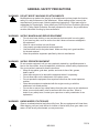
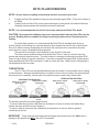
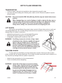
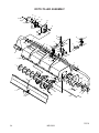
OPERATOR’S AND PARTS MANUAL ROTO-TILLER SERIAL NUMBER: ___________________ Manual Number: MR15639 Part Number: LAF3438, MODEL NUMBER: ___________________ LAF3452 & LAF3468 Rev. 3 800-456-7100 I www.paladinattachments.com 503 Gay Street, Delhi, IA 52223, United States of America Copyright © 1/2/14 THIS PAGE IS INTENTIONALLY BLANK 4 MR15639 1/2/14 TABLE OF CONTENTS PREFACE .......................................................................................................................................... 3 SAFETY PRECAUTIONS SAFETY STATEMENTS ........................................................................................................ 4 GENERAL SAFETY PRECAUTIONS ................................................................................ 4-6 EQUIPMENT SAFETY PRECAUTIONS.............................................................................. 7-8 DECALS DECAL PLACEMENT............................................................................................................. 9 DECALS.................................................................................................................................10 INSTALLATION..................................................................................................................................11 OPERATION................................................................................................................................. 12-15 BEFORE OPERATION OPERATING THE TILLER TINE ROTATION STORAGE TRANSPORTING LIFT POINTS TIE DOWN POINTS MAINTENANCE AND SERVICE.................................................................................................. 16-17 ROUTING MAINTENANCE CHAIN ADJUSTMENT REPLACING THE HYDRAULIC MOTOR REPLACING RIGHT BEARING ASSEMBLY REPLACING LEFT BEARING ASSEMBLY REPLACING TINE ASSEMBLY REPLACING CHAIN AND SPROCKETS TROUBLESHOOTING.......................................................................................................................18 SPECIFICATIONS ........................................................................................................................... 19 BOLT TORQUE SPECIFICATIONS...................................................................................................20 WARRANTY.......................................................................................................................................21 PARTS TILLER ASSEMBLY ....................................................................................................... 22-25 1/2/14 MR15639 1 THIS PAGE IS INTENTIONALLY BLANK 2 MR15639 1/2/14 PREFACE GENERAL COMMENTS Congratulations on the purchase of your new attachment! This product was carefully designed and manufactured to give you many years of dependable service. Only minor maintenance (such as cleaning and lubricating) is required to keep it in top working condition. Be sure to observe all maintenance procedures and safety precautions in this manual and on any safety decals located on the product and on any equipment on which the attachment is mounted. This manual has been designed to help you do a better, safer job. Read this manual carefully and become familiar with its contents. WARNING! Never let anyone operate this unit without reading the "Safety Precautions" and "Operating Instructions" sections of this manual. Always choose hard, level ground to park the vehicle on and set the brake so the unit cannot roll. Unless noted otherwise, right and left sides are determined from the operator’s control position when facing the attachment. NOTE: The illustrations and data used in this manual were current (according to the information available to us) at the time of printing, however, we reserve the right to redesign and change the attachment as may be necessary without notification. BEFORE OPERATION The primary responsibility for safety with this equipment falls to the operator. Make sure the equipment is operated only by trained individuals that have read and understand this manual. If there is any portion of this manual or function you do not understand, contact your local authorized dealer or the manufacturer to obtain further assistance. Keep this manual available for reference. Provide the manual to any new owners and/or operators. SAFETY ALERT SYMBOL This is the “Safety Alert Symbol” used by this industry. This symbol is used to warn of possible injury. Be sure to read all warnings carefully. They are included for your safety and for the safety of others working with you. SERVICE Use only manufacturer replacement parts. Substitute parts may not meet the required standards. Record the model and serial number of your unit on the cover of this manual. The parts department needs this information to insure that you receive the correct parts. SOUND AND VIBRATION Sound pressure levels and vibration data for this attachment are influenced by many different parameters: some items are listed below (not inclusive): • prime mover type, age, condition, with or without cab enclosure and configuration • operator training, behavior, stress level • job site organization, working material condition, environment Based on the uncertainty of the prime mover, operator, and job site, it is not possible to get precise machine and operator sound pressure levels or vibration levels for this attachment. NOTE: A list of all Paladin Patents can be found at http://www.paladinattachments.com/patents.asp. 1/2/14 MR15639 3 SAFETY STATEMENTS THIS SYMBOL BY ITSELF OR WITH A WARNING WORD THROUGHOUT THIS MANUAL IS USED TO CALL YOUR ATTENTION TO INSTRUCTIONS INVOLVING YOUR PERSONAL SAFETY OR THE SAFETY OF OTHERS. FAILURE TO FOLLOW THESE INSTRUCTIONS CAN RESULT IN INJURY OR DEATH. DANGER THIS SIGNAL WORD IS USED WHERE SERIOUS INJURY OR DEATH WILL RESULT IF THE INSTRUCTIONS ARE NOT FOLLOWED PROPERLY. WARNING THIS SIGNAL WORD IS USED WHERE SERIOUS INJURY OR DEATH COULD RESULT IF THE INSTRUCTIONS ARE NOT FOLLOWED PROPERLY. CAUTION NOTICE THIS SIGNAL WORD IS USED WHERE MINOR INJURY COULD RESULT IF THE INSTRUCTIONS ARE NOT FOLLOWED PROPERLY. NOTICE INDICATES A PROPERTY DAMAGE MESSAGE. GENERAL SAFETY PRECAUTIONS WARNING! READ MANUAL PRIOR TO INSTALLATION Improper installation, operation, or maintenance of this equipment could result in serious injury or death. Operators and maintenance personnel should read this manual, as well as all manuals related to this equipment and the prime mover thoroughly before beginning installation, operation, or maintenance. FOLLOW ALL SAFETY INSTRUCTIONS IN THIS MANUAL AND THE PRIME MOVER'S MANUAL(S). READ AND UNDERSTAND ALL SAFETY STATEMENTS Read all safety decals and safety statements in all manuals prior to operating or working on this equipment. Know and obey all OSHA regulations, local laws, and other professional guidelines for your operation. Know and follow good work practices when assembling, maintaining, repairing, mounting, removing, or operating this equipment. KNOW YOUR EQUIPMENT Know your equipment’s capabilities, dimensions and operations before operating. Visually inspect your equipment before you start, and never operate equipment that is not in proper working order with all safety devices intact. Check all hardware to ensure it is tight. Make certain that all locking pins, latches, and connection devices are properly installed and secured. Remove and replace any damaged, fatigued, or excessively worn parts. Make certain all safety decals are in place and are legible. Keep decals clean, and replace them if they become worn and hard to read. 4 MR15639 1/2/14 WARNING! GENERAL SAfETy PRECAUTIONS GENERAL SAFETY PRECAUTIONS PROTECT AGAINST fLyING DEbRIS wearFLYING proper safety glasses, goggles, or a face shield when driving pins in or WARNING! PROTECT always AGAINST DEBRIS out, or when any operation causes dust, debris, any other hazardous mateAlways wear proper safety glasses, goggles or a faceflying shield when or driving pins in or out, or whenrial. any operation causes dust, flying debris, or any other hazardous material. WARNING! LOWER OR SUPPORT EQUIPMENT WARNING! LOWER ORRAISED SUPPORT RAISED EQUIPMENT not raised work under raised booms withoutthem. supporting them. not use Do not work Do under booms without supporting Do not use Do support support mate- rialofmade of concrete logs, buckets, or any other material that could material made concrete blocks, blocks, logs, buckets, barrels barrels, or any other material that suddenly collapse shift positions. sure support material is solid, could suddenly collapse or shiftorpositions. MakeMake sure support material is solid, not not decayed,twisted, warped,ortwisted, or Lower tapered. lowertobooms ground levelblocks. or on blocks. lower decayed, warped, tapered. booms groundtolevel or onto booms and attachments the ground leaving theorcab or operator’s station. Lower booms and attachments to thetoground beforebefore leaving the cab operator’s station. WARNING! USE CARE WITH HyDRAULIC fLUID PRESSURE WARNING! USE CAREHydraulic WITH HYDRAULIC FLUIDcan PRESSURE fluid under pressure penetrate the skin and cause serious injury or Hydraulic fluid under pressure can penetrate the skin and serious injuryconnecting or death. hydraulic leaks under pressure may notcause be visible. before or dis- death. Hydraulic leaks under pressure be prime visible.mover’s Beforeoperator’s connectingmanual or for detailed connecting hydraulic hoses,may readnot your disconnecting hydraulic hoses, read your prime movers operator’s manual for detailed instructions on connecting and disconnecting hydraulic hoses or fittings. instructions on connecting and disconnecting hydraulic hoses or fittings. • Keep unprotected body parts, such as face, eyes, and arms as far away as • Keep unprotected body parts, such as face, eyes, and armswith as far away as possible from a suspected leak. Flesh injected hydraulic fluid may develop possible from a suspected leak. Flesh injected with hydraulic fluid may develop or other disabilities. permanent disabilities. gangrene organgrene other permanent injured fluid, by injected fluid, see a doctor at once. If your is not with • If injured• by Ifinjected see a doctor at once. If your doctor is notdoctor familiar withfamiliar this type of injury, ask him to research it immediately to determine proper treat this type of injury, ask him to research immediately to determine proper treatment. • Wear safetyment. glasses, protective clothing, and use a sound piece of cardboard or • Wear safety protective clothing, and use a piece of cardboard or wood wood when searching forglasses, hydraulic leaks. DO NOT USE YOUR HANDS! when searching for hydraulic leaks. DO NOT USE yOUR HANDS! SEE ILLUSTRATION. SEE ILLUSTRATION. CARDbOARD HyDRAULIC HOSE OR fITTING MAGNIfyING GLASS 4 1/2/14 MR15639 5 76288 GENERAL SAFETY PRECAUTIONS WARNING! DO NOT MODIFY MACHINE OR ATTACHMENTS Modifications may weaken the integrity of the attachment and may impair the function, safety, life, and performance of the attachment. When making repairs, use only the manufacturer’s genuine parts, following authorized instructions. Other parts may be substandard in fit and quality. Never modify any ROPS (Roll Over Protection Structure) or FOPS (Falling Object Protective Structure) equipment or device. Any modifications must be authorized in writing by the manufacturer. WARNING! SAFELY MAINTAIN AND REPAIR EQUIPMENT • Do not wear loose clothing, or any accessories that can catch in moving parts. • • • • If you have long hair, cover or secure it so that it does not become entangled in the equipment. Work on a level surface in a well-lit area. Use properly grounded electrical outlets and tools. Use the correct tool for the job at hand. Make sure they are in good condition for the task required. Wear the protective equipment specified by the tool manufacturer. WARNING! SAFELY OPERATE EQUIPMENT Do not operate equipment until you are completely trained by a qualified operator in how to use the controls, know its capabilities, dimensions, and all safety requirements. See your machine's manual for these instructions. • Keep all step plates, grab bars, pedals, and controls free of dirt, grease, debris, and oil. • Never allow anyone to be around the equipment when it is operating. • Do not allow riders on the attachment or the prime mover. • Do not operate the equipment from anywhere other than the correct operators position. • Never leave equipment unattended with the engine running or with this attachment in a raised position. • Do not alter or remove any safety feature from the prime mover or this attachment. • Know your work site safety rules as well as traffic rules and flow. When in doubt on any safety issue, contact your supervisor or safety coordinator for an explanation. WARNING! KNOW WHERE UTILITIES ARE Observe overhead electrical and other utility lines. Be sure equipment will clear them. 6 When digging, call your local utilities for location of buried utility lines, gas, water, and sewer, as well as any other hazard you may encounter. MR15639 1/2/14 EQUIPMENT SAFETY PRECAUTIONS WARNING! EXPOSURE TO RESPIRABLE CRYSTALLINE SILICA DUST ALONG WITH OTHER HAZARDOUS DUSTS MAY CAUSE SERIOUS OR FATAL RESPIRATORY DISEASE. It is recommended to use dust suppression, dust collection and if necessary personal protective equipment during the operation of any attachment that may cause high levels of dust. WARNING! REMOVE PAINT BEFORE WELDING OR HEATING Hazardous fumes/dust can be generated when paint is heated by welding, soldering or using a torch. Do all work outside or in a well ventilated area and dispose of paint and solvent properly. Remove paint before welding or heating. When sanding or grinding paint, avoid breathing the dust. Wear an approved respirator. If you use solvent or paint stripper, remove stripper with soap and water before welding. Remove solvent or paint stripper containers and other flammable material from area. Allow fumes to disperse at least 15 minutes before welding or heating. WARNING! END OF LIFE DISPOSAL At the completion of the useful life of the unit, drain all fluids and dismantle by separating the different materials (rubber, steel, plastic, etc.). Follow all federal, state and local regulations for recycling and disposal of the fluid and components. OPERATING THE TILLER • • • • • • • • • 1/2/14 Stay clear of tiller when engine is running. Keep others away. Keep hands, feet and clothing away from moving parts. Never allow anyone to reach into, kick into or otherwise come in contact with the rotating tines. Do not attempt to clear clogged tines while engine is running. Tines can crush and/or dismember. Keep everyone clear of the tiller until proper shut down procedure has been followed and hydraulic pressure has been relieved. Operate only from the operator’s station. To prevent serious injury or death from thrown objects, stay away from discharge area during operation. Reduce speed when driving over rough terrain, on a slope, or turning, to avoid overturning the vehicle. An operator must not use drugs or alcohol, which can change his or her alertness or coordination. An operator taking prescription or over-the-counter drugs should seek medical advice on whether or not he or she can safely operate equipment. Before exiting the prime mover, lower the attachment to the ground, apply the parking brakes, turn off the prime mover’s engine, and remove the key. Be sure all doors, guards and shields are in their proper position and securely attached before operating the tiller. MR15639 7 EQUIPMENT SAFETY PRECAUTIONS TRANSPORTING THE TILLER • • • • Travel only with the attachment in a safe transport position to prevent uncontrolled movement. Drive slowly over rough ground and on slopes. When driving on public roads use safety lights, reflectors, Slow Moving Vehicle signs etc., to prevent accidents. Check local government regulations that may affect you. Do not smoke when refueling the prime mover. Allow room in the fuel tank for expansion. Wipe up any spilled fuel. Secure cap tightly when done. When transporting on a trailer: Secure attachment at recommended tie down locations using tie down accessories that are capable of maintaining attachment stability. MAINTAINING THE TILLER • • • • • 8 Before performing maintenance, lower the attachment to the ground, apply the parking brakes, turn off the prime mover’s engine, and remove the key. Never perform any work on the attachment unless you are authorized and qualified to do so. Always read the operator service manual’s before any repair is made. After completing maintenance or repair, check for correct functioning of the attachment. If not functioning properly, always tag “DO NOT OPERATE” until all problems are corrected. Worn, damaged, or illegible safety decals must be replaced. New safety decals can be ordered from Paladin. Never make hydraulic repairs while the system is under pressure. Serious personal injury or death could result. Never work under a raised attachment. MR15639 1/2/14 DECALS The diagram on this page shows the location of the decals used on the FFC Tiller. The decals are identified by their part numbers, with reductions of the actual decals located on the following page. Use this information to order replacements for lost or damaged decals. Be sure to read all decals before operating the attachment. They contain information you nee to know for both safety and product longevity. RDL3100 Serial # Tag RDL3100 RDL3178 40150 40151 IMPORTANT: Keep all safety decals clean and legible. Replace all missing, or damaged safety decals. When replacing parts with safety decals attached, the safety decals must also be replaced. REPLACING SAFETY DECALS: Clean the area of application with a nonflammable solvent, then wash the same area with soap and water. Allow the surface to dry. Remove the backing from the safety decal, exposing the adhesive surface. Apply the safety decal to the position shown in the diagram, and smooth out any bubbles. 1/2/14 MR15639 9 DECALS PART #40150 WARNING! READ MANUAL PART #40151 WARNING! HIGH PRESSURE FLUID PART #RDL3100 WARNING! STAND CLEAR 10 PART #RDL3178 CAUTION! NOT A STEP MR15639 1/2/14 INSTALLATION GENERAL INFORMATION The FFC Tillers covered in this manual were designed to be used on various prime movers with various different horsepower, operating capacities and lifting capacities. Before installing the attachment you have received onto your prime mover, verify that your attachment is compatible with your prime mover. Check to be certain each unit is within the limitations of the other. Operating the attachment on a prime mover that exceeds any of the recommended specifications will cause damage to the attachment and void all warranties. INSTALLATION Install the attachment by following your power units operator’s manual for installing an attachment. WARNING! To avoid serious personal injury, make sure the attachment is securely latched to the attachment mechanism of your unit. Failure to do so could result in separation of the attachment from the prime mover. With the auxiliary hydraulic system turned off, route the hydraulic hoses over tiller housing in such a fashion as to avoid pinching and chafing of the hoses and connect them to their proper auxiliary couplers on the loader. Carefully raise the loader and cycle the tilt cylinders to check clearances and to verify that all mounting procedures have been successfully completed. Check for proper assembly, installation and hydraulic leaks. WARNING! Do not lock the auxiliary hydraulics of your prime mover in the "ON" position. Failure to obey this warning could result in death or serious injury. WARNING! Do not operate a standard flow tiller on a high flow hydraulic system or a high flow tiller on a standard flow hydraulic system. Serious injury or equipment damage may occur. DETACHING On firm level ground, lower the loader arms until the attachment is on the ground. Turn off the engine. Move control levers back and forth to relieve pressure in the line. Disconnect couplers. NOTE: Seal hydraulic system from contaminants and secure all hydraulic hoses off the ground to help prevent damage. Follow your prime mover’s operator’s manual for detaching (removing) an attachment. 1/2/14 MR15639 11 ROTO-TILLER OPERATION INTENDED USE: This unit is designed to cultivate soil for planting or landscaping. Use in any other way is considered contrary to the intended use. The FFC Roto-Tiller is perfect for home gardening, landscaping and vegetable farming just to mention a few. It turns up hard packed ground and leaves the perfect seedbed for gardens or lawns. Simplicity of operation is one of the key features of the FFC Roto-Tiller. It is important, however, to be familiar with and know the controls and adjustments on both the Roto-Tiller and the prime mover. Such knowledge is crucial for safe, efficient operation of the equipment. Some information may be general in nature due to unknown and varying operating conditions. However, through experience and these instructions, you should be able to develop procedures suitable to your particular situation. THE PRIME MOVER The Roto-Tiller mounts to the attachment mechanism of your prime mover. Due to this arrangement thorough knowledge of the prime mover controls is necessary for Roto-Tiller operation. Read your prime movers operator's manual for information regarding operation before attempting to use the attachment. BEFORE OPERATING THE ROTO-TILLER • Clear the work area of all bystanders, pets and livestock. • Be sure all Roto-Tiller tines, bolts and nuts are tight and chain guards are in place. • Clear the area of rocks, branches and other foreign objects. • Tall grass and weeds may need to be mowed before tilling to avoid wrapping around the tine assembly, therefore reducing the Roto-Tiller performance. DANGER! ROTATING TINES HAZARD! To prevent serious injury or death from rotating tines: Stay clear of Roto-Tiller when engine is running. Keep others away. Keep hands, feet and clothing away from moving parts. Follow Safety Shutdown Procedure whenever leaving operator's station. DANGER! THROWN OBJECT HAZARD! To prevent serious injury or death from thrown objects stay away from discharge area during operation. Keep others away. OPERATING THE ROTO-TILLER The main purpose of the FFC Roto-Tiller is to cultivate soil. The Roto-Tiller is bi-directional; it will operate with the tines rotating in either direction. After thoroughly checking the Roto-Tiller and preparing the work area you are ready to begin tilling. NOTE: Although the performance of the Roto-Tiller can vary significantly depending upon the way it is used, we recommend the following operating procedure for maximum productivity. 1. Following the prime mover manuals operating and safety procedures, start the prime mover and position the Roto-Tiller at the starting location. 2. With the prime mover at idle speed and the arms fully back and lowered, Roto-Tiller will be slightly off of the ground, engage the auxiliary hydraulic to begin Roto-Tiller rotation. 12 MR15639 1/2/14 ROTO-TILLER OPERATION NOTE: Be sure tines are rotating in the desired direction for prime mover travel. 3. 4. Position the Roto-Tiller parallel to the ground and increase engine RPM. (Tines will cut better at full RPM). Carefully lower the Roto-Tiller to the ground and begin to slowly travel in the desired direction. Gradually increase speed until the desired results are achieved. NOTE: It is recommended after the first 50 feet to stop and check to Roto-Tiller depth. CAUTION! Be prepared for sudden prime mover movement when lowering Roto-Tiller into the ground. Rotating tines are capable of pulling or pushing the prime mover, depending on tine rotation. For finish tilling operation, it is recommended the Roto-Tiller be operated while driving in reverse with the tines rotating in a clockwise direction when viewed from the left side of the machine. Due to the offset mounting configuration this will allow the right tracks to be covered as the prime mover moves in reverse, finishing the tilling operation. Tilling should not be done in wet conditions as soil will stick to the tines. There are several conditions that will cause the Roto-Tiller to "walk up" onto the top of the ground and push/pull the prime mover. The most common is traveling too fast and low engine RPM (tines moving to slowly for ground conditions). If you have increased the engine RPM and decreased travel speed and the Roto-Tiller continues to "walk up" check the tines. Make sure the cutting edge is still sharp and all tines are intact. TINE ROTATION The FFC Roto-Tiller can be operated while traveling in forward or reverse and the tines rotating in either direction. Although standard direction of rotation is for the tines to rotate in the same direction the prime-mover is traveling, reversing the tine rotation has been noted to bury debris better. REVERSE TINE ROTATION STANDARD TINE ROTATION DIRECTION OF TRAVEL DIRECTION OF TRAVEL DIRECTION OF TRAVEL DIRECTION OF TRAVEL RECOMMENDED FOR FINISH TILLING The auxiliary hydraulics must be engaged so that: • the tines rotate down into the untilled area in the direction of travel to achieve the fastest tilling speeds and the most efficient use of power, or • the tines rotate up from under the untilled area in the direction of travel to achieve greatest conditioning of the soil. IMPORTANT Tilling while moving forward with the hinged shroud panel fully down CAN result in damage to this product and WILL void all FFC warranties. 1/2/14 MR15639 13 ROTO-TILLER OPERATION IMPORTANT Attempting to grind stumps or dig into rigid or frozen materials CAN result in damage to this product and WILL void all FFC warranties. • • • When tilling while moving forward, the hinged shroud panel must be chained up in a horizontal position to avoid damaging the panel. The hinged shroud panel is not designed to push any soil or other materials. Your prime mover should be operating at full throttle with the auxiliary hydraulics fully engaged. The speed of the movement of your prime mover should be varied as required to pulverize the soil to extent desired. The maximum tilling depth is 6". This depth is attained when the motor guard is about 1" below the surface of the soil. Compacted soils may require two passes to reach this depth. STORAGE The following procedure will help you to keep your unit in top condition. It will also help you get off to a good start the next time your tiller is needed. We therefore strongly recommend that you take the extra time to follow this procedure whenever your tiller will not be used for and extended period of time. PREPARATION FOR STORAGE • • Clean the unit thoroughly, removing all mud, dirt and grease. Inspect for visible signs of wear, breakage or damage. Inspect the tines for wear. Order any parts required and make the necessary repairs to avoid delays when starting next season. NOTE: Purchase only approved parts from your authorized dealer. When replacing tines it is recommended that you replace mounting hardware also. • • • • • • Tighten all loose nuts, bolts and hydraulic connections. Connect the hydraulic couplers together or cap them to protect the hydraulic system from contaminates. Replace decals if damaged or in unreadable condition. Grease all grease fittings (if so equipped). Seal hydraulic system from contaminants and secure all hydraulic hoses off the ground to help prevent damage. Store the unit in a dry and protected place. Leaving the machine outside will materially shorten its life. Additional Precautions for Long Term Storage: • Touch up all unpainted and exposed areas with paint to prevent rust. REMOVAL FROM STORAGE • • • Remove all protective coverings. Check hydraulic hoses for deterioration and replace if necessary. Check all nuts, bolts and hydraulic connections for tightness. 14 MR15639 1/2/14 ROTO-TILLER OPERATION TRANSPORTING • • Follow all federal, state and local regulations when transporting on public roads. Use extra care when loading and unloading onto a trailer or truck. Disconnect hydraulic couplers during transport. CAUTION! Be sure to install a SMV (Slow Moving Vehicle) sign on loader before transporting. When transporting on a road or highway at night or during the day, use accessory lights and devices for adequate warning to the operators of other vehicles. In this regard, check local and government regulations. Always drive slowly over uneven terrain to avoid tipping the unit. LIFT POINTS Lifting points are identified by lifting decals where required. Lifting at other points is unsafe and can damage attachment. Do not attach lifting accessories around cylinders or in any way that may damage hoses or hydraulic components. • • • Attach lifting accessories to unit at recommended lifting points. Bring lifting accessories together to a central lifting point. Lift gradually, maintaining the equilibrium of the unit. WARNING! Use lifting accessories (chains, slings, ropes, shackles and etc.) that are capable of supporting the size and weight of your attachment. Secure all lifting accessories in such a way to prevent unintended disengagement. Failure to do so could result in the attachment falling and causing serious personal injury or death. TIE DOWN POINTS Tie down points are identified by tie down decals where required. Securing to trailer at other points is unsafe and can damage attachment. Do not attach tie down accessories around cylinders or in any way that may damage hoses or hydraulic components. • • Attach tie down accessories to unit as recommended. Check unit stability before transporting. WARNING! Verify that all tie down accessories (chains, slings, ropes, shackles and etc.) are capable of maintaining attachment stability during transporting and are attached in such a way to prevent unintended disengagement or shifting of the unit. Failure to do so could result in serious personal injury or death. 1/2/14 MR15639 15 MAINTENANCE AND SERVICE GENERAL INFORMATION Regular maintenance is the key to long equipment life and safe operation. Maintenance requirements have been reduced to the absolute minimum. However, it is very important that these maintenance functions be performed as described below. Procedure Daily Every 40 Hours Check all bolts and nuts for tightness. Replace any missing bolts or nuts with approved replacement parts. Check hydraulic system for hydraulic oil leaks. See procedure below. Visually inspect the machine for worn parts or cracked welds, and repair as necessary. Check all guards are securely in place. Lubricate all grease fittings. Check taper lock adapter assembies for tightness by turning teh bearing locknut by hand. If locknut moves, retighten the taper lock adapter assembly as specified. See "Bearing Lock Adjustment". NOTE: Avoid using a high pressure pneumatic lubricating equipment on the tiller shaft bearings. These bearings are assembled with special high dirt exclusion seals. High pressure lubricating equipment can damage the seals. WARNING! Do not operate the tiller during maintenance or while any guards are removed. WARNING! Escaping fluid under pressure can have sufficient force to penetrate the skin, causing serious personal injury. Fluid escaping from a very small hole can be almost invisible. Use a piece of cardboard or wood, rather than hands, to search for suspected leaks. Keep unprotected body parts, such as face, eyes, and arms as far away as possible from a suspected leak. Flesh injected with hydraulic fluid may develop gangrene or other permanent disabilities. If injured by injected fluid, see a doctor at once. If your doctor is not familiar with this type of injury, ask him to research it immediately to determine proper treatment. 16 MR15639 1/2/14 ROTO-TILLER SERVICE IMPORTANT: When replacing parts use only factory approved replacement parts. Manufacturer will not claim responsibility for use of unapproved parts or accessories and/or other damages as a result of their use. Removing Wire, Twine, Weeds, etc. that are Wrapped Around the Roller 1. Park your prime mover on a level surface with this product properly attached. 2. Place your prime mover's transmission in "Park" and engage the parking brake. 3. Lower this product onto preplaced blocking that will support the motor guards of this product so that the tines are not in contact with the ground. WARNING! Failure to obey the following procedures could result in death or serious injury. · 4. 5. 6. Do not use blocking made of concrete blocks, logs, buckets, barrels or any other material that could suddenly collapse or shift positions. Do not use wood or steel blocking that shows any signs of material decay. Do not use blocking that is warped, twisted, or tapered. Shut off your power unit’s engine, remove the starter key, wait for all moving parts to come to a stop, and relieve all pressure in the hydraulic lines. Disconnect the hydraulic lines from your power unit and connect the two ends to each other. This should permit the tines to rotate freely. Pull the material from the tine shaft while allowing the shaft to rotate. ALTERNATE METHOD If your power unit is equipped with safety stops for the lift arms of the loader that can be activated from the operator’s position or if the safety stops must be activated from outside the operator’s position and a second person is present, then Step 3 above may be replaced with these steps: a) Fully raise the lift arms and fully extend the tilt cylinders to the fully dumped position. b) Activate the safety stops for the lift arms. Test the stops to verify that no downward movement of the lift arms can occur. c) Continue with Step 4 above. Replacing Tines 1. Perform steps 1 through 5 above. 2. Remove the clip and pin that secure the strip; then slide the tine out. a) If most of the tilling is done in one direction, the tine may be reversed and reinstalled. NOTICE 3. 4. To achieve the best tilling results, all the tines should be reversed at one time, not just one or two tines at a time. b) If the tine is worn out or damaged, properly dispose of the tine and install a new tine. Replace the pin and clip. Repeat the process for all other tines. Bearing Lock Adjustment 1. Bend the locking tang of the bearing lock washer out to free the bearing lock nut. 2. Loosen the bearing lock nut. 3. Retighten the bearing lock nut until finger - tight. 4. Tighten the lock nut an additional 1-1/4 turns and, if necessary, continue tightening until the first time one tang of the bearing lock washer is aligned with a notch on the locknut. 5. Bend that tang of the bearing lock washer back into the notch on the lock nut. 1/2/14 MR15639 17 ROTO-TILLER TROUBLESHOOTING PROBLEM POSSIBLE CAUSE POSSIBLE SOLUTION Roto-Tiller is not rotating. Loader auxiliary hydraulics not engaged. Refer to loader operator's manual. Inadequate hydraulic flow from loader. Check hydraulic flow to Roto-Tiller. Low oil supply. Add oil. Couplers not engaged. Engage couplers. Air in hydraulic lines. Activate system until air is purged from system. Broken hose. Replace damaged hose. Obstruction in hydraulic lines. Remove obstruction and replace if necessary. Loose or damaged hydraulic connection. Tighten or replace fittings. Obstruction between Roto-Tiller and housing. Remove obstruction. Hydraulic motor damaged or seal blown. Call FFC service department for instructions. Key sheared or missing. Check and replace motor key or drive shaft key as required. Roto-Tiller carried by loader. Lower loader arms. Insufficient power. Increase engine RPM. Worn or bent tines. Replace as necessary. Obstacles entangled in tine assembly. Clear obstacles from tine assembly. Tillage depth insufficient. Roto-Tiller making excessive noise Bearings worn or damaged. and/or vibrating. Replace as needed. Roto-Tiller skips or leaves grass residue. Badly worn tines. Replace as needed. Ground speed too fast for soil conditions. Reduce ground speed. Soil texture too coarse. Roto-Tiller RPM too slow. Increase RPM. Ground speed too fast. Reduce ground speed. Roto-Tiller bumping on ground. Obstacles entangled in tine assembly Clear obstacles from tine assembly. Tines balling up with soil. Soil too wet. Delay tilling until soil dries. Worn or bent tines. Replace as needed. Ground speed too fast for soil conditions. Reduce ground speed. 18 MR15639 1/2/14 PRIME MOVER SPECIFICATIONS IMPORTANT Exceeding any of the maximum recommended prime mover specifications CAN result in damage to this product and WILL void all FFC warranties. DESCRIPTION SPECIFICATIONS Rated net Engine Horsepower of Prime Mover 110 hp. maximum Weight of Prime Mover without Roto-Tiller 11,000 lbs. maximum Operating Capacity of Prime Mover's loader 3,600 lbs. maximum Lift Capacity of Prime Mover's loader 7,200 lbs. maximum Hydraulic Pressure Output 3,500 psi maximum Rear Ballast As required to maintain full prime mover stability. (Note the Shipping Weight on the specifications page, then see the operator’s manual(s) for your prime mover, loader, and quick-attach for ballasting needs.) Model Number Overall Width LAF3438 LAF3452 LAF3468 53" 67.81" 78.25" ROTO-TILLER SPECIFICATIONS Overall Height Overall Depth Offset to Right Torque @ 2,500 psi Shipping Weight 27" 27" 27" 27" 33.5" 33.5" varies 12.5" 4.75" 469 ft. lbs 939 ft. lbs. 939 ft. lbs. 450 lbs. 600 lbs. 695 lbs. All replacement hydraulic hoses must have a minimum rated working pressure of 4,000 psi. 1/2/14 MR15639 19 BOLT TORQUE BOLT TORQUE SPECIFICATIONS GENERAL TORQUE SPECIFICATION TABLES 8VHWKHIROORZLQJFKDUWVZKHQGHWHUPLQLQJEROWWRUTXHVSHFL¿FDWLRQVZKHQVSHFLDOWRUTXHVDUHQRW given. Always use grade 5 or better when replacing bolts. SAE BOLT TORQUE SPECIFICATIONS NOTE: The following torque values are for use with extreme pressure lubricants, plating or hard washer applications Increase torque 15% when using hardware that is unplated and either dry or lubricated with engine oil. SAE GRADE 5 TORQUE Bolt Size Inches Millimeters 1/4 6.35 5/16 7.94 3/8 9.53 7/16 11.11 1/2 12.70 9/16 14.29 5/8 15.88 3/4 19.05 7/8 22.23 1 25.40 1-1/8 25.58 1-1/4 31.75 1-3/8 34.93 1-1/2 38.10 Pounds Feet UNC UNF 8 9 14 19 30 36 46 54 68 82 94 112 128 153 230 275 340 408 493 592 680 748 952 1054 1241 1428 1649 1870 Newton-Meters UNC UNF 11 12 19 23 41 49 62 73 92 111 127 152 174 207 312 373 461 553 668 803 922 1014 1291 1429 1683 1936 2236 2535 SAE GRADE 8 TORQUE Pounds Feet UNC UNF 10 13 20 25 38 46 60 71 94 112 136 163 187 224 323 395 510 612 765 918 1088 1224 1547 1700 2023 2312 2686 3026 Newton-Meters UNC UNF 14 18 27 34 52 62 81 96 127 152 184 221 254 304 438 536 691 830 1037 1245 1475 1660 2097 2305 2743 3135 3642 4103 METRIC BOLT TORQUE SPECIFICATIONS %ROWKHDGLGHQWL¿FDWLRQPDUNVDVSHUJUDGH NOTE: Manufacturing Marks Will Vary %ROWKHDGLGHQWL¿FDWLRQPDUNVDVSHUJUDGH NOTE: The following torque values are for use with metric hardware that is unplated and either dry or lubricated with engine oil. Reduce torque 15% when using hardware that has extreme pressure lubricants, plating or hard washer applications. Size of Bolt Grade No. 5.6 Pitch (mm) Pounds Feet 3.6-5.8 Newton-Meters 4.9-7.9 Pitch (mm) Pounds Feet - Newton-Meters - M6 8.8 10.9 1.0 5.8-.4 7.2-10 7.9-12.7 9.8-13.6 - - - 12-17 16.3-23 M8 8.8 10.9 1.0 19-27 22-31 25.7-36.6 29.8-42 20-29 27.1-39.3 M10 8.8 10.9 1.25 35-47 40-52 47.4-63.7 54.2-70.5 31-41 42-55.6 M12 8.8 10.9 1.25 56-68 62-75 75.9-92.1 84-101.6 52-64 70.5-86.7 M14 8.8 10.9 1.5 90-106 107-124 122-143.6 145-168 69-83 93.5-112.5 1.5 120-138 140-158 162.6-187 189.7-214.1 100-117 136-158.5 1.5 177-199 202-231 239.8-269.6 273.7-313 132-150 178.9-203.3 1.5 206-242 246-289 279.1-327.9 333.3-391.6 7.2-14 9.8-19 1.25 17-22 20-26 23-29.8 27.1-35.2 20-25 27.1-33.9 1.5 34-40 38-46 46.1-54.2 51.5-62.3 28-34 37.9-46.1 1.75 51-59 57-66 69.1-79.9 77.2-89.4 49-56 66.4-75.9 2.0 81-93 96-109 109.8-126 130.1-147.7 67-77 90.8-104.3 2.0 116-130 129-145 157.2-176.2 174.8-196.5 88-100 119.2-136 2.0 150-168 175-194 203.3-227.6 237.1-262.9 108-130 146.3-176.2 2.5 186-205 213-249 252-277.8 288.6-337.4 5.6 5.6 5.6 5.6 5.6 M16 8.8 10.9 M18 8.8 10.9 5.6 5.6 M20 76312 20 8.8 10.9 MR15639 1/2/14 29 Limited Warranty Except for the Excluded Products as described below, all new products are warranted to be free from defects in material and/or workmanship during the Warranty Period, in accordance with and subject to the terms and conditions of this Limited Warranty. 1. Excluded Products. The following products are excluded from this Limited Warranty: (a) Any cable, part that engages with the ground (i.e. sprockets), digging chain, bearing, teeth, tamping and/or demolition head, blade cutting edge, pilot bit, auger teeth and broom brush that either constitutes or is part of a product. (b) Any product, merchandise or component that, in the opinion of Paladin Light Construction1, has been (i) misused; (ii) modified in any unauthorized manner; (iii) altered; (iv) damaged; (v) involved in an accident; or (vi) repaired using parts not obtained through Paladin Light Construction. 2. Warranty Period. The Limited Warranty is provided only to those defects that occur during the Warranty Period, which is the period that begins on the first to occur of: (i) the date of initial purchase by an end-user, (ii) the date the product is first leased or rented, or (iii) the date that is six (6) months after the date of shipment by Paladin Light Construction as evidenced by the invoiced shipment date (the “Commencement Date”) and ends on the date that is twelve (12) months after the Commencement Date. 3. Terms and Conditions of Limited Warranty. The following terms and conditions apply to the Limited Warranty hereby provided: (a) the product. Option to Repair or Replace. Paladin Light Construction shall have the option to repair or replace (b) Timely Repair and Notice. In order to obtain the Limited Warranty, (i) the product must be repaired within thirty (30) days from the date of failure, and (ii) a claim under the warranty must be submitted to Paladin Light Construction in writing within thirty (30) days from the date of repair. (c) Return of Defective Part or Product. If requested by Paladin Light Construction, the alleged defective part or product shall be shipped to Paladin Light Construction at its manufacturing facility or other location specified by Paladin Light Construction, with freight PRE-PAID by the claimant, to allow Paladin Light Construction to inspect the part or product. Claims that fail to comply with any of the above terms and conditions shall be denied. LIMITATIONS AND EXCLUSIONS. THIS LIMITED WARRANTY IS IN LIEU OF ALL OTHER WARRANTIES, EXPRESS OR IMPLIED, INCLUDING WITHOUT LIMITATION THE WARRANTIES OF MERCHANTABILITY, FITNESS FOR A PARTICULAR PURPOSE AND ANY WARRANTY BASED ON A COURSE OF DEALING OR USAGE OF TRADE. IN NO EVENT SHALL PALADIN LIGHT CONSTRUCTION BE LIABLE FOR CONSEQUENTIAL OR SPECIAL DAMAGES. IN NO EVENT SHALL PALADIN LIGHT CONSTRUCTION BE LIABLE FOR ANY LOSS OR CLAIM IN AN AMOUNT IN EXCESS OF THE PURCHASE PRICE, OR, AT THE OPTION OF PALADIN LIGHT CONSTRUCTION, THE REPAIR OR REPLACEMENT, OF THE PARTICULAR PRODUCT ON WHICH ANY CLAIM OF LOSS OR DAMAGE IS BASED. THIS LIMITATION OF LIABILITY APPLIES IRRESPECTIVE OF WHETHER THE CLAIM IS BASED ON BREACH OF CONTRACT, BREACH OF WARRANTY, NEGLIGENCE OR OTHER CAUSE AND WHETHER THE ALLEGED DEFECT IS DISCOVERABLE OR LATENT. Attachment Technologies Inc., a subsidiary of Paladin Brands Holding, Inc. (PBHI) is referred to herein as Paladin Light 21 Construction. 1/2/14 MR15639 February 10, 2010 1 ROTO-TILLER ASSEMBLY 26 25 49 26 46 25 50 44 23 45 23 20 16 13 42 34 10 18 37 12 41 35 39 24 47 14 40 37 38 19 29 11 15 6 43 36 33 48 17 9 13 22 23 3 23 1 4 27 25 26 5 21 32 22 25 28 7 31 2 MR15639 26 25 8 26 28 1/2/14 14 ROTO-TILLER ASSEMBLY ITEM QTY. LAF3438 LAF3452 LAF3468 38" 52" 68" DESCRIPTION 1 1 2 varies (20) (28) (36) LAF3400 Tine 3 varies (1) (2) (2) LAF3401 Motor Guard 4 varies (1) (2) (2) LAF3402 Motor Mounting Plate 5 varies (1) (2) (2) LAF3403 Motor-Tine Shaft Coupler 6 1 LAF3416 LAF3404 LAF3408 Shroud 7 1 LAF3414 LAF3405 LAF3409 Hinged Shroud Panel 8 1 LAF3415 LAF3406 LAF3411 Hinge Pin 9 1 LAF3413 LAF3407 LAF3410 Tine Shaft Weldment 10 1 Not Used 34114 Rubber Metal Edge 5" 11 1 Not Used 34114 Rubber Metal Edge 5" 12 2 3219 Jamb Nut #10 13 varies (2) (4) (4) 3431 Hydraulic Fitting 10MB-10MJ Straight 14 varies (1) (2) (2) 21956 Hydraulic Motor 15 2 Not Used 30430 16 2 Not Used LAF4657 17 2 LAF4552 (84") 18 4 LAF9447 19 1 1023 Grade 5 Hex Head Cap Screw .31" x 1.25" 20 1 1031 Grade 5 Hex Head Cap Screw .31" x 3.25" 21 varies (4) (8) (8) RHW1406 Grade 5 Hex Head Cap Screw .5" x 1.75" 22 varies (1) (2) (2) 1148 Grade 5 Hex Head Cap Screw .75" x 4.5" 23 16 24 varies (2) (1) (1) 1502 Grade 5 Lock Washer .31" 25 varies (20) (24) (24) 1505 Grade 5 Lock Washer .5" 26 varies (20) (24) (24) 1228 Grade 5 Hex Nut .5" 13 tpi 27 varies (1) (2) (2) 1936 Grade 5 Lock Nut .75" 28 varies (22) (30) 29 2 31 varies 32 1 RHW8317 33 1 22315 Hose Clamp Plate 34 1 22315 Hose Clamp Plate 35 2 22316 Hose Clamp Cradle 36 1 RHW8618 DHF2021 Not Used LAF4659 (32") LAF4657 (48") 1872 (28) Bulkhead Run Tee 10MJ-10MJ-10MJ Hydraulic Hose .5" x 48" 10FJ-10FJ Hydraulic Hose .5" x (length noted) 10FJ-10FJ Anti-Slip Abrasive Tape 4" x 12" Grade 5 Carriage Bolt .5" x 1.5" (38) RHW8011 Grade 2 Cotter Pin .13" x 1.25" 105840 (20) Chain 18 links (36) RHW8134 Fender Washer .34" x 1.5" OD x 10 GA Grade 8 Clevis Pin .5" x 1.25" D-Shackle with .31" Dia. Round Pin & Cotter Pin, Galvanized Spring 1.5" x 11.63" with 7.25" Coil NOTE: All parts are the same as the LAF3468 except for those parts numbered under the other models. *ITEM may vary per Prime Mover -- Contact FFC for correct item. 1/2/14 MR15639 23 ROTO-TILLER ASSEMBLY 26 25 49 26 46 25 50 44 23 45 23 20 16 13 42 34 10 18 37 12 41 35 39 24 47 14 40 37 38 19 29 11 15 6 43 36 33 48 17 9 13 22 23 3 23 1 4 27 25 26 5 21 32 24 25 28 7 31 2 MR15639 26 25 8 26 14 28 1/2/14 ROTO-TILLER ASSEMBLY ITEM QTY. 37 2 *38 1 LAF3438 LAF3452 LAF3468 38" 52" 68" DESCRIPTION 7104 Tie Strap .3" x 15.25" Plastic Contact FFC to obtain correct item. Hydraulic Hose Protector 39 2 *40 2 Contact FFC to obtain correct item. Hydraulic Elbow (not required on all models) *41 2 Contact FFC to obtain correct item. Hydraulic Adapter (not required on all models) *42 1 19632 Hydraulic Hose Quick Coupler: Male Connection *43 1 22518 Hydraulic Hose Quick Coupler: Female Connection 44 1 LAF3418 Not Used Not Used Dust Guard 45 1 LAF3512 Not Used Not Used Bearing Taper Lock Adapter 46 1 LAF3513 Not Used Not Used Rotor Bearing 47 1 1513 48 1 RHW8642 .31" Rivet Nut 49 1 53031 Not Used Not Used Grease Zerk .25", 90°, Self-tapping, 28 tpi 50 1 LAF3417 Not Used Not Used Bearing Mount Not Used 03-10025 Hydraulic Hose .63" x 78" 10FJ-12MB Sheathed Grade 5 Flat Washer .31" USS NOTE: All parts are the same as the LAF3468 except for those parts numbered under the other models. *ITEM may vary per Prime Mover -- Contact FFC for correct item. 1/2/14 MR15639 25