1
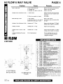
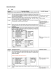
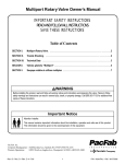
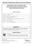
p"~ex
tr~tonHI FLOW
"6WAY VALVE4 '/2 f I
Pool and Spa Systems
INSTALLATION, OPERATION & SERVICE MANUAL
WARNING
THIS MANUAL CONTAINS
CRITICAL SAFETY INFORMATION WHICH MUST BE
FURNISHED TO THE END
USER. FAILURE TO READ
AND FOLLOW INSTRUCTIONS COULD RESULT I N
SERIOUS PERSONAL INJURY AND/OR MAJOR
PROPERTY DAMAGE.
TABLE OF CONTENTS
A. H O W YOUR VALVE WORKS.. . . . . . . 2
B. INSTALLA'rION . . . . . . . . . . . . . . . . . . . . . . . . . 2
C. REPLACEMENT OF VALVE TOP
AND DIVERTER ASSEMBLY . . . . . . . . . . 3
D. VALVE CARE . . . . . . . . . . . . . . . . . . . . . . . . . . . . 3
E. WINTERIZING PROCEDURE . . . . . . . . . . 3
F. TROUBLESHOO'rlNG GUIDE . . . . . . . . . 4
G. REPLACEMENT PARTS... . . . . . . . . . . . . . . 4
MEMBER
I
'9
NATIONAL
S P A h POOL
INSTITUTE
Y
C
O
R
P
O
R
A
T
E
PACFAB HEADQUARTERS
1620 Hawkins Ave., Sanford, NC 27330
D
(919) 774-4151
PACFAB WESTERN OPERATIONS
10951 W. Los Angeles Ave.. Moorpark. CA 93021 (805) 523-2400
PACFAB EUROPE
lndustriepark Wolfstee 8-2200. Herentals. Belgium Phone (01 1) 3214125.99.11
pulex
triton,
Pool and Spa Systems
PAGE 2
HI FLOW 6 WAY VALVE
This valve operates under pressure. When closed properly a n d
operated without air in the water system, this valve will operate in a
safe manner.
C A R E F U L L Y R E A D A N D FOLLOW ALL S A F E T Y
INSTRUCTIONS I N T H I S MANUAL O R ON FILTER.
Your six position valve is designed to provide all the necessary
positions required to operate, maintain, trouble shoot and service
your filter. It is provided with six operating positions and one Winterize position. The valve is constructed of high quality corrosion
resistant materials and when installed, operated, and maintained
in accordance to these instructions your valve will provide years of
trouble free operation.
-
WARNING
Air entering t h e filter a n d a valve c l a m p n o t closed properly
c a n c a u s e t h e v a l v e t o b l o w off a n d could c a u s e s e v e r e bodily
injury a n d / o r property damage. (Some valve models d o n o t
h a v e a c l a m p b u t t h r e a d i n t o t h e f i l t e r tank.)
-
-
-
-
1-This valve is equipped with a n external air bleeder device -item 12.
Always open this air bleeder and stand clear of filter and valve
before starting system pump and leaveopen until a steady stream of
water is expelled.
CAUTION: To prevent equipment damage and possible injury,
always turn pump off before changing valve position.
2-This valve has a closed position. The pump should never be on
when the valve is in the closed position. If the pump is operated with
the valvr closed, the air relief system becomes inoperative and an
explosive situation could exist. Additionally, running the system
with no flow will seriously damage the equipment.
VALVE: POSITIONS:
FIL'L'ER -
HACKWASH -
RINSE -
WASTE
-
CLOSED RECIRCULATE
From Pump, through valvcdownwardTHKI~
FILTER up through center pipe to valve
RETIJKN port for normal filter action and
vacuuming pool thru filter.
From pump through valvr, down through
center pipe and to valve WASTE port for
cleaning filter by reversing flow.
From p u m p , t h r o u g h vnlve d o w n w a r d
up through filter up through center pipe t ~ )
valve WASTE Port for start-up cleaning and
resetting filter bed after backwashing.
From pump through valve BY PASSES HI,TER and goes to WASTE port for vacuuming
directly to waste, lclwering pool level, or
draining pool.
NO FLOW - DO NOT USE THIS SETTING
WITH PUMP OPERATING.
From pump, through valve, bypasses filter
and goes to return port for circulating water
without going thru filter.
1-Check carton for any evidence of damagedue to rough handling in
shipment. If carton or any valve components are damaged, notify
freight carrier immediately.
NOTICE:
When w o r k i n g i n a n d a r o u n d t h e c l a m p u s e c a u t i o n t o p r e vent potential injury t o fingers o r h a n d s from sudden cont a c t w i t h s h a r p edges.
2-After inspection, carefully remove valve components from carton.
Be sure sand h a s been placed into filter, sand guide h a s been
removed a n d top of filter cleaned of any sand or debris.
NOTE: T h e f i l t e r v a l v e w i l l a t t a c h t o t h e f i l t e r i n o n e o f t w o
w a y s d e p e n d i n g u p o n t h e f i l t e r a n d v a l v e type.
Clamp style valves utilize a clamp which holds
together the flanges of t h e valve a n d filter. Follow exactly,
steps 3 t h r u 8below t o attach t h e valve t o t h e filter. (Disreg a r d s t e p s 9 t h r u 12).
3-Check to be sure item 13 o-ring is in place in groove on valve body.
(Note: Item numbers in this portion of the instruction booklet refer
to the replacement parts list titled Hi-Flow Six Way Valve).
4-Open clamp item 14 wide enough to place over the flange on the
tank and rest on the tank before the valve is installed.
5-Place valve over opening in top of tank so that filter centerpipe
slips into bore of valve body.
6-Valve ports arc labeled with the location of where they should be
connected i.e. pump port must go to pump discharge, waste port
must go to the waste line and return port must go to the pool return.
7-Orient the valve to allow the ports to be plumhed to the proper
location.
8-Press down on vnlve so th,it itern 13 0 - r l n g is tiown insid(, of
openlng of tank top.
-- - -
-
-
-
-
WARNING
I m p r o p e r t a n k v a l v e a s s e m b l y could c a u s e t h e v a l v e t o b l o w
off a n d c a u s e s e v e r e i n j u r y a n d / o r p r o p e r t y d a m a g e .
1,ift the clampitem 14 over the tank flange a n d carefully guidc the
cIamp so that it catches t ~ o t hthe valve flange and the tank flange.
'righten "T" bolt nut securely.
T h r e a d e d s t y l e v a l v e s utilize a l a r g e 6" b u t t r e s s t h r e a d t h a t
s c r e w s directly t o t h e filter tank. Follow exactly, steps 9
t h r u 12 b e l o w t o a t t a c h t h e v a l v e t o t h e f i l t e r . ( D i s r e g a r d
s t e p s 3 t h r u 8).
9 Check to be sure o-ring, Item 18, is in place above large thread on
valvc body and that o-ring is lubricated. If o-ring requires lubrication, us(%only silicont' type lubrication.
WARNING
U s e of l u b r i c a n t s o r pipe s e a l a n t s o t h e r t h a n r e c o m m e n d e d
in this instruction booklet, c a n d a m a g e t h e valve a n d cause
t h e v a l v e t o b l o w off a n d could c a u s e s e v e r e bodily i n j u r y o r
property damage.
10-Check to be sure filter piping assembly is exactly centered about
1
below the large threaded opening in the tank.
'lq"
11-Carefully install the valve inside the filter opening so that the
filter piping assembly slips into socket of the valve. Slowly turn
valve clockwise until the thread engages with the thread on the
tank. Continue to turn valve until the O-ring on valve contacts the
tank. Grasp valve by the two opposing ports and tighten as secure
a s possible by hand.
HI FLOW 6 WAY VALVE
WARNING
Do n o t install pipes into t h e threaded ports, f o r t h e purpose
a f g a i n i n g m e c h a n i c a l a d v a n t a g e , as t h i s c a n o v e r t i g h t e n
n d d a m a g e t h e v a l v e a n d c a n c a u s e t h e v a l v e t o b l o w off
r e s u l t i n g i n s e v e r e bodily i n j u r y a n d / o r p r o p e r t y d a m a g e .
NOTE: T h e v a l v e s h o u l d n o t become h a r d t o t u r n w h e n
installing i n t h e filter opening until t h e valve o-ring cont a c t s t h e filter surface. Failure to position t h e filter piping
assembly i n t h e center of t h e large filter opening, c a n cause
t h e v a l v e t o n o t t h r e a d p r o p e r l y i n t o t h e filter t a n k .
12 Orient the filter with valve to allow the ports to he plumbed to the
proper location.
I:!-'I'he Maximum operating pressure of this valve is 50 psi. The
filter unit also has a maximum operating pressure listed on the filter
nameplate. DO NOT OPERATE this unit above the maximum
operating prcssure of the valve o r the filter. Never connect the filter
and valve unit to a punlp which can generate a pressure that
cxcceds the o p e r a t i ~ ~pressure
g
o f t h c filter o r valve.
14-Assernblr piping and pipe fittings to pump and valve. All piping
must confor~nto 1oc;rl and state plumbing and sanitary codcs.
15-IJsclsealant on 2311 tapercld m;dc cwnnections of pipe and fittings.
lJse only sealant compounds suited for plastic pipe. Support pipe to
prcvclnt strains on filter, pump or valve.
NOTICK:
All vlilve i n t e r n a l t h r e a d s a r e t a p e r e d e x c e p t t h e a i r b l e e d e r
c o n n e c t i o n . 110 n o t o v e r t i g h t e n t a p e r e d t h r e a d c o n n e c t i o n s .
( i ~ 1 1 1 s tpressure
~~ll
gage in 1 4" NPT port directly across from the
PAGE 3
WARNING
I m p r o p e r t a n k v a l v e a s s e m b l y could c a u s e t h e v a l v e t o b l o w
off a n d c a u s e s e v e r e i n j u r y a n d / o r p r o p e r t y d a m a g e .
7-Place the new valve top handle in the winterize position. Install
new valve top and diverter assembly making sure small recess on
lid and small bump on valve body are aligned. Start all 6 screws
with fingers to insure that the screw is started in the formed thread
of the valve I~ody.screws should be tightened progressively by
tightening di:~metricallyopposite screws and following a crisscross
pattern. Tighten all f valve top attachment screws firmly. DO NOT
OVEK'I'IGH'I'EN.
NOTICE: V a l v e t o p i s a t t a c h e d w i t h s e l f - t a p p i n g s c r e w s .
T h e s c r e w s must be aligned properly t o prevent cross
t h r e a d i n g o f t h e s c r e w s i n t h e v a l v e body.
The valve is a very important part ot' your pool equipment and
inst;lllation. Proper care and maintenanre, will add many years of
for long
service and cnjoymcnt to thc pool. Follow these suyyc%stions
troul~l(sfree operation.
I-'1'0 (,leanthe exterior ofthc valvc~ofdustand d ~ r twash
,
w~th
u mild
tietergcnt and water and then hose off r)o not use solvents.
WARNING
Always visually inspect valve components d u r i n g n o r m a l
servicing t o insure structural safety. Replace a n y item
w h i c h i s c o r r o d e d , b e n t o r o t h e r w i s e v i s u a l l y defective.
Defective v a l v c c o m p o n e n t s c a n a l l o w t h e v a l v e o r a t t a e h m e n t s t o b l o w off a n d could c a u s e s e v e r e bodily i n j u r y o r
property damage.
pump port.
17-bi\j,vc.r
stc~rc,pool chemicals within 10 feet of your pool filter valve.
t'ool c,hemic,;ils should always br stc~redin a cool, dry, well ventilatcd ;ir.c>;1.
WARNING
C h e m i c a l f u m e s a n d / o r spills c a n c a u s e s e v e r e a t t a c k o f
filter valve structural components. Structurally weakened
components c a n cause filter valve o r attachments t o blow
off a n d could c a u s e s e v e r e bodily i n j u r y a n d / o r p r o p e r t y
damage.
%-Thevalve clamp uscd on your valve has 11cc.n rn;~nuf;icturedwith
prohigh clu:~lityc.or.r.osionresistant materials. l'hr rn;~r~uf':~cturing
c.csss cc~uldallow s h a r p edgcs to be present on the parts. When
working in and around the clamp use caution to prrvent pc~tential
injury to fingers or hands from contact with s h a r p c.dgcss.
:(byour valve is a prc,ssurc vessel and should nc1vc.r be serviced while
undrr prc%ssure.Always relievc. tank pressure and oprn air t~lccder
l)c,t'~)re
attempting to st~rvicc~
your valve.
4-Opcn the ~ n a n u n lair t~lcedcrand stand rlcar o f t h e filterivalvc
before restarting your pump.
I-Shut off pump and open the valve air bleeder.
I-Shut off pump and open air bleeder to relieve all internal pressure.
%Set valve handlc to winterize position
:i-Remove 6 cover screws (Item 10).
4-Lift off valve top and diverter assemhly
NOTICE: V a l v e d i v e r t e r a s s e m b l y h a s t h e s e a l i n g g a s k e t
a t t a c h e d t o t h e d i v e r t e r . When h a n d l i n g t h e d i v e r t e r u s e
caution t o prevent t h e sealing surface from being damaged
d u r i n g handling.
5-Clean valve body sealing surface with soft clean lint free cloth.
Inspect surface for damage such a s scratches or nicks. If surface is
damaged the valve body must be replaced.
6-Carefully lubricate the new valve top replacement "On Ring Item
6 with a silicone based lubricant and place appropriately on valve
top
2-Drain and winterize the pump and filter per manufacturer's
instructions
:3-llcpressvalve handle and rotate so valve pointer is on circular rib
on valvc top a t area on valve marked WINrI'EKI%E.
NOTICE: T h e v a l v e s h o u l d b e l e f t i n t h i s p o s i t i o n d u r i n g t h e
shutdown season s o t h e valve diverter h a s n o pressure o n
t h e rubber seal.
HI FLOW 6 WAY VALVE
Problem
Leak to waste port
Leakage at port connections to valve
Sand Returning to Pool
PAGE 4
Cause
1. Dirt or sand under seal.
Remove valve top and clean seal area.
2. Damaged seal.
Replace valve top assembly.
3. Damaged valve body i n seal area.
Replace valve body.
1. Cracked ports.
Replace valve body use proper assembly
and d o not over tighten port
connection.
2. Did not use sealant on threads.
Use sealant.
1. Filter problem.
Refer to filter manual.
2. Sand blowing thru air vent slots or
between filter center pipe in valve.
Sand size too small or flow rate thru filter
too high.
Leakage at valve attachment to filter
Leakage past "0" Ring.
Remove valve and inspect "0"Ring &
sealing surface replace as necessary.
Leakage at handle
Leakage past "0" Ring.
Replace valve top assembly.
Leakage at top of valve to valve
body.
Leakage past "0" Ring.
Remove valve and inspect "0"Ring &
sealing surface replace as necessary.
Leakage at sightglass with vacuum
breaker
Dirt on Sealing Gasket
Remove sightglass and rinse with
cool water to remove dirt. Replace
sightglass i f damaged.
HI FLOW
,
6 WAY VALVE
6
7
8
8A
9
10A
11A
llB
12
13
14
15
16
16
17
18
-
19
20
21
6" BUTTRESS
STYLE VALVE
REV. E 8/98
CLAMP STYLE
VALVE
27220
27-2505
27-2405
27-2527
27-2511
35-4053
27-2401
27-2400
27-2535
27-2512
35-4541
27-2530
27-2538
27-3512
27-2541
15-2162
15-5050
27-1106
27-2550
27-1107
15-4493
15-5037
27-2517
27-2555
27-2554
35-4562
AD
WASHER-PLASTIC
SCREW-HANDLE
VALVE TOP-BLACK
O S N G - DIVERTER SHAFT
1
O-RING
1
WASHER-STAINLESS STEEL SEE NOTE 4
1
SPRING-100 LB. 1 13/16 O.D. SS SEE NOTE 4 SPRING-100 LB. - 1 'I8 O.D. SS (SEE NOTE 4)
1
DIVERTER WIGASKET
1
SCREW # 10-24 HEX PAN HD (SEE NOTE 5)
6
VALVE BODY WIDIFFUSER-CLAMP STYLE
1
VALVE BODY WIDIFFUSER-THREADED STYLE
1
1
AIR BLEEDER WIO-RING (SEE NOTE 3)
O-RING - 3/16" x 4 518" I.D.
1
CLAMP
1
PRESSURE GAUGE
1
SIGHTGLASS
SIGHTGLASS WIVACUUM PROTECTOR
1
1
GASKET-SIGHTGLASS 5/8" I.D. x 1" O.D.
1
O-RING ,157'' x 5.75" I.D.
1
CARTON
1
INSTRUCTIONS - 6 POSITION VALVE
6
WASHER 9/16 SS (SEE NOTE 5)
6
NUT- # 10-24 SERRATED FLANGE SS [SEE NOTE 5)
LABEL-NO PETROLEUM
1
-
7
NOTE:
VALVE TOP ASSEMBLY PIN 27-2531 CONSISTS OF ITEMS 1 THRU 9 AND
VALVE INSTRUCTIONS27-2517.
2. VALVES MANUFACTURED BEFORE MARCH 1,1993 DO NOT CONTAIN ITEM
16 SIGHTGLASS OR ITEM 17 SIGHTGLASS GASKET.
3. CLAMP STYLE VALVES MANUFACTURED BEFORE MARCH 1,1993 CONTAIN
A DIFFERENT AIR BLEEDER WlTH O-RING PART NO. 27-2515. THIS PART IS
NOT INTERCHANGEABLE WlTH PART NO. 27-3512. THREADED VALVES
MANUFACTURED BEFORE MARCH 1, 1993 DO NOT CONTAIN AN AIR
BLEEDER WlTH O-RING.
4. ITEM BA USED ON VALVES MANUFACTURED AFTER MAY 1, 1992 AN0
REPLACES BOTH ITEMS 7 AND B.
5. VALVES MANUFACTURED AFTER APRIL 15, 1994 USE NUTIBOLT DESIGN.
SEE ITEMS 10A. 19. 20, 8 21.
1.
27-2517
Remedy