1
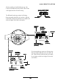
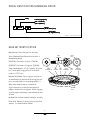
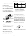
Spicer Drive Axles
®
Service Manual
Spicer® Drive Axles
AXSM-8663
September 2007
TABLE OF CONTENTS
Axle Identification .................................................................... 1
Identification ............................................................................. 2
Model Identification Numbering System
Gear Set
Axle Lubricant Recommendations......................................... 3
General Precautions ................................................................. 4
Axle Components ..................................................................... 5
Removal ...................................................................................... 6
Differential Carrier from Axle Housing
Differential from Carrier
Differential Disassembly ......................................................... 7
Pinion Above Center Applications ........................................ 8
Pinion Disassembly .................................................................. 9
Cleaning and Inspection ......................................................... 10
Pinion Assembly ........................................................................ 11
Pinion Position .......................................................................... 13
Pinion Setting Chart................................................................. 14
Differential Assembly ............................................................... 16
Differential Installation ............................................................ 17
Ring Gear and Pinion Tooth Contact Pattern .................... 18
Wheel Bearing Adjustment ..................................................... 19
Installation of Differential Carrier Into Axle Housing ....... 20
Axle/Torque Specifications .................................................... 21
Recommended Service Tools ................................................. 22
GENUINE SPICER SERVICE PARTS
Should an axle assembly require replacement component
parts, it is recommended that Spicer Heavy Axle Service
Parts be used. Spicer Heavy Axle Service Parts are
manufactured under the same rigid specification as are
original equipment axle components. This assures the
customer who uses genuine Spicer service parts, maximum reliability for a Spicer Heavy Axle assembly. They
may be obtained through your vehicle manufacturer.
The use of non-original Spicer service parts may cause
premature component failure and may void the warranty.
The items included in this book are currently being offered
as service parts at the time of printing. The part numbers
and illustrations are provided specifically for reference
purposes only. Therefore, Spicer reserves the right to
update this manual without notice or liability.
i
AXLE IDENTIFICATION
All axle assemblies are identified with two tags. One
located on the differential carrier, and the other located
on the right hand side of the axle housing.
JULIAN D
ATE CODE
DA
97 0
70
07
The differential carrier tag contains the following:
Dana part number, julian date code, and ratio. Optional
items include customer part number, line set number, and
the last six digits of the vehicle serial number.
MODEL YEAR
DANA P
AR
T
PAR
ART
NUMBER
DAY OF YEAR
CUS
TOMER
CUST
PAR
T NUMBER
ART
(OPTIONAL)
JULIAN D
ATE
DA
CODE
Carrier Tag
LAS
T SIX DIGITS OF
LAST
VEHICLE SERIAL NUMBER
(OPTIONAL)
DANA P
AR
T
PAR
ART
NUMBER
CUS
TOMER
CUST
T NUMBER
PAR
ART
(OPTIONAL)
Axle Assembly Tag
LAS
T SIX DIGITS OF
LAST
VEHICLE SERIAL NUMBER
(OPTIONAL)
LINE SET
NUMBER
(OPTIONAL)
The axle assembly tag contains the following items:
Dana part number, julian date code, axle model, and
ratio. Optional items include customer part number,
line set number, and the last six digits of the vehicle
serial number.
MODEL
JULIAN D
ATE
DA
CODE
LINE SET
NUMBER
(OPTIONAL)
1
MODEL IDENTIFICATION NUMBERING SYSTEM
Famil
amilyy
Load Carr
ying Capacit
Carrying
Capacityy
(1
55 = 1
5,5
00 Lbs.)
(15
15,5
5,500
(1
70 = 1
7,000 Lbs.)
(17
17
F
1
70
17
S N
Op
tions
Options
(N= No-SPIN® op
tion)
option)
Gearing T
ype
Type
educ
tion)
Reduc
eduction)
(S= Single R
* No-SPIN® is a registered trademark of Tractech
GEAR SET IDENTIFICATION
Manufacturer's Date- Date gear set was made.
Spicer Trademark- Dana Diamond and location of
manufacturing facility.
PINION
ETCH
SPICER
TRADEMARK
+15
029GP100- Part number of pinion. (TYPICAL)
Tooth Combination(i.e. 41-11)- Indicates the pinion
has 11 teeth and the ring gear has 41 teeth which
results in a 3:73:1 ratio.
260
41-11
029GR107- Part number of ring gear. (TYPICAL)
TOOTH
COMBINATION
Matched Set Number- Spicer ring gears and pinions
are manufactured as matched sets. Both ring gear and
pinion are marked with a corresponding number (i.e.
401), which identifies them as a matched set.
PART
NUMBER
HEAT
CODE
SPICER
TRADEMARK
MFG.
DATE
MATCHED
SET NUMBER
401
L10
A gear set that does not have the same match set
numbers should not be run together. If either ring gear
or pinion require replacement, a new matched set must
be used.
BACKLASH
ETCH
Backlash Etch- Indicates backlash setting for assembly.
Pinion Etch- Indicator for proper pinion position shim
stack up. See Pinion Position Section.
2
AXLE LUBRICANT RECOMMENDATIONS
To ensure proper lubrication and operating temperature,
correct lubricants and lubricant levels must be obtained.
APPLICATION
On Highway
RECOMMENDED LUBRICANTS
Mineral or Synthetic based hypoid gear lubricants that
meet or exceed military specification MIL-L-2105D, and
API service classification GL-5, are the minimum requirements for use in Spicer Medium and Heavy Duty Drive
Axles.
PETROLEUM BASED
SYNTHETIC BASED**
MILES
INTERVAL
MILES
INTERVAL
100,000
1 Year
250,000
3 Year
and
50,000
On-Off Highway
1 Year
100,000
1 Year
* Severe Service
* Severe service includes any applications operating at
or near maximum GVW or GCW ratings. This
includes normally wet or dusty environments, or
consistent heavy load and low speed applications.
The table below indicates which SAE viscosities are
recommended for various temperature ranges the vehicle
will encounter.
** Includes Semi-Synthetic blends that meet
MIL-L-2105D specifications.
AFTER OVERHAUL OR CHANGE INTERVALS
Fill the axle assembly to the bottom of housing fill hole
as shown in the illustration below. It is recommended
that following an overhaul, each side of the axle be
jacked up seperately to approximately six inches and held
into position for one minute. This procedure will allow
adequate lubricant to flow into the wheel ends and help
eliminate the possibility of premature damage to wheel
bearings and seals. Lower the vehicle to the floor and
allow ten minutes for lube to return to normal level.
Check and refill assembly to bottom of fill hole to replace
the lubricant that was directed into the wheel ends.
Ambient Air Temperature
SERVICE
Recommended lubricant change intervals are dependent
on the application and operating environment. The
following chart should be used to establish proper
change intervals.
SUBMERSION OR DEEP WATER FORDING
In the event the axle assembly should become
submerged in water, particularly if over the vent or
breather, it is recommended that the lubricant be
drained and all parts be inspected for water damage
and/or contamination. Reassemble the carrier to the
housing and refill with specifed gear lubricant.
NOTE: Lubricant close enough to the bottom of the fill hole to be seen or touched
is not sufficient. Lubricant must be level with the fill hole.
3
GENERAL PRECAUTIONS
IMPORTANT
READ THIS SECTION BEFORE STARTING
ANY SERVICE PROCEDURES
GENERAL AXLE DESCRIPTION
This manual covers maintenance and rebuild procedures for the Spicer F155-S and F170-S rear drive axle
assemblies.
Accordingly, anyone who uses a service procedure or
tool different than shown must insure that their safety,
and the vehicle's safety, will not be jeopardized by the
service method selected.
The Spicer Heavy Duty Single Reduction rear drive axle
is a full floating axle assembly, with a hypoid gear carrier
assembly, using a High Strength Low Alloy (HSLA) steel
axle housing. The hypoid pinion is straddle mounted
with two tapered roller bearings behind the pinion teeth
for thrust and radial loads. A pilot bearing is located on
the nose of the pinion for radial load. The differential
itself uses four precision forged pinion mate gears, a
forged cross, and precision forged side gears.
END YOKES AND FLANGES
CAUTION: Hammering on end yokes can close
in the bearing bores or misalign yoke lugs and result
in early failures of journal needle bearings or other
driveline components. Serious damage can also be
done internally to the ring and pinion set or pinion
bearings by hammering on external parts. End yokes
or companion flanges should be removed or installed
using the recommended methods outlined in this
manual.
Safety glasses should be worn
at all times when assembling
or disassembling axles.
CLEANLINESS
Axle components should be steam cleaned prior to
removal from the vehicle. Dirt is abrasive and will cause
premature wear of otherwise serviceable parts.
Service personnel should use a wash tank for thorough
cleaning of parts just prior to reassembly.
SAFTEY PRECAUTIONS
Proper service and repair of vehicle components is
important to the safe and reliable operation of all motor
vehicles. This applies particularly to driving axles such as
the ones described in this manual. The procedures
recommended and described in this manual are tested,
effective methods for performing service operations.
Follow each procedure closely, making use of both the
text and illustrations. Some of these service procedures
show the use of certain tools designed specifically for
the operation being performed. They are shown as a
preferred means of performing the operation. It is not
practical to anticipate and advise the service trade of all
possible alternative methods, and of all possible hazardous consequences that could occur.
CAUTION
BRAKE LININGS CONTAIN NON-ASBESTOS FIBERS
BREATHING BRAKE DUST MAY BE HAZARDOUS TO YOUR HEALTH AND
MAY CAUSE SERIOUS RESPIRATORY OR OTHER BODILY HARM.
AVOID CREATING DUST
DO NOT REMOVE BRAKE DRUM WITHOUT PROPER PROTECTIVE EQUIPMENT.
DO NOT WORK ON LININGS WITHOUT PROPER PROTECTIVE EQUIPMENT.
DO NOT REPLACE LININGS WITHOUT PROPER PROTECTIVE EQUIPMENT.
DO NOT ATTEMPT TO SAND, GRIND, CHISEL, FILE, HAMMER OR ALTER BRAKE
LININGS IN ANY MANNER WITHOUT PROPER PROTECTIVE EQUIPMENT.
FOLLOW 0.S.H.A. STANDARDS FOR PROPER PROTECTIVE DEVICES TO BE USED
WHEN WORKING WITH BRAKE MATERIALS.
4
AXLE COMPONENTS
Axle Shaft
Housing
Vent Plug
Fill Plug
(35-45 Lb-Ft)
(47-61 N-m)
Differential Bearing Cap
Hex Bolt
(7-9 Lb-Ft)
(9-12 N-m)
Differential Bearing Cap Bolt
(115-135 Lb-Ft)
(155-183 N-m)
Magnetic Drain Plug
(35-45 Lb-Ft)
(47-61 N-m)
Differential Bearing
Cap Washer
Washer
Oil Scoop
Adjusting Ring
Differential Bearing Cup
Differential Bearing Cone
Differential Case Bolt
Differential Pinion Mate
Thrust Washer
Differential Pinion Mate
Differential Cross Shaft
Differential Side Gear
Differential Case
Flange Half
Differential Gear
Thrust Washer
Pinion-Up Components
Ring Gear
Oil Scoop
Ring Gear Rivet
Cotter
Pin
Carrier Housing
Adjusting Ring
Lock
Ring Gear Bolt Kit
(300-320 Lb-Ft)
(406-434 N-m)
Oil Deflector
Pinion Position Shim(s)
Differential Case Nut
(75-90 Lb-Ft)
(100-120 N-m)
Pinion Pilot Bearing
Differential Case
Cap Half
®
No-SPIN Differential
Carrier Mounting Bolt
(100-120 Lb-Ft)
(136-162 N-m)
Pinion
Inner Pinion Bearing Cone
Inner Pinion Bearing Cup
Outer Pinion
Bearing Cone
Pinion
Oil Seal
Pinion Bearing Spacer
(Selective)
Pinion Bearing Cage
Outer Pinion Bearing Cup
Pinion Bearing Cage Bolt
(160-180 Lb-Ft)
(217-244 N-m)
(Optional)
End Yoke
Assembly
Flanged Hex Nut
(700-900 Lb-Ft)
(950-1,220 N-m)
5
REMOVAL OF DIFFERENTIAL
CARRIER FROM AXLE HOUSING
NOTE: Steam clean axle assembly.
6. Remove axle shafts.
1. Block wheels.
7. Support the differential carrier assembly on a roller
jack. Secure as necessary to prevent it from
falling off the jack when removed from the housing.
2. Remove axle housing drain plug and drain lubricant.
3. Disconnect drive shafts at the rear U-joint.
8. Use a breaker bar to loosen the differential carrierto-housing mounting bolts. Remove all bolts except
top two. These two bolts will prevent the carrier
assembly from falling.
NOTE: If end yoke and/or seal is to be replaced,
loosen yoke nut at this time.
4. Remove axle shaft flange nuts.
9. Separate differential carrier from the housing. Be
certain carrier is balanced properly on jack, and
remove top two carrier-to-housing mounting bolts.
Remove differential carrier assembly from the axle
housing.
5. Hold a large brass drift or a brass hammer against
the center of the axle shaft flange. Strike the drift
with sharp blows from a large hammer or sledge
until the axle shaft separates from the hub.
CAUTION: Do not strike the flange directly
with a steel hammer or sledge. This may crack and
splinter material, possibly causing serious or fatal
injury. Do not pry or chisel axle flange away from
hub or damage to sealing surfaces could occur.
Mount carrier assembly in a suitable rebuild stand.
(Refer to Recommended Service Tools, pg. 22).
Differential Carrier Removal Complete
REMOVAL OF DIFFERENTIAL FROM CARRIER
1. Remove adjusting ring locks from bearing caps.
3. Loosen four bearing cap retainer bolts.
2. Match mark one differential bearing cap and leg with
center punch or chisel for correct reassembly. See
Figure 1.
4. Loosen adjusting rings, relieving bearing preload.
5. Remove four bearing cap retainer bolts.
6. Remove bearing caps.
7. Remove adjusting rings.
8. Carefully lift the ring gear and differential
subassembly out of the carrier.
NOTE: Use care not to damage the ring gear and
pinion. If either ring gear or pinion show signs of
damage, they must be replaced as a matched set.
Removal of Differential Complete
Figur
iguree 1
6
DIFFERENTIAL DISASSEMBLY
Differential Bearing Cap
Differential Gear Thrust Washer
Hex Bolt
(7-9 Lb-Ft)
(9-12 N-m)
Washer
Ring Gear
Oil Scoop
Adjusting
Ring
Differential
Bearing Cone
Differential Side Gear
Differential Pinion Mate Thrust Washer
Differential Case Bolt
Differential Pinion Mate
Differential Bearing Cap Bolt
(115-135 Lb-Ft)
(155-183 N-m)
Differential Bearing
Cap Washer
Differential Case Flange Half
Ring Gear Rivet
Cotter Pin
Ring Gear Bolt Kit
(300-320 Lb-Ft)
(406-434 N-m)
Differential Cross Shaft
Adjusting Ring
Lock
Differential
Bearing Cup
Differential Case Cap Half
Differential Case Nut
(75-90 Lb-Ft)
(100-120 N-m)
(Optional)
1. Match mark differential case halves with punch or
chisel for correct alignment during reassembly. See
Figure 2.
Figur
iguree 3
Figur
iguree 2
6. If differential side bearings are to be replaced,
remove old bearings using suitable puller. See
Figure 3.
2. Remove differential case nuts and lift off the
differential case half.
3. Remove thrust washer and differential side gear.
NOTE: Inspect all parts, including the machined
surfaces of the case itself.
4. Lift out cross shaft, pinion mates and thrust washer.
5. Remove second differential side gear and thrust
washers.
7
DIFFERENTIAL DISASSEMBLY
8. Next, use a round type punch to drive out the
remaining portion of the rivet.
IMPORTANT: If any gears are to be replaced, they
must be replaced in sets. Inspect thrust washers for
scoring and excessive wear. Replace all worn or
damaged parts.
CAUTION: Always use a soft hammer or H.D.
plastic head hammer to strike punch.
7. When it is necessary to remove ring gear from
differential case, carefully center punch each rivet
head. Use a 9/16" drill bit and drill through rivet
heads. See Figure 4.
NOTE: Do not use a chisel to remove rivet heads,
damage to differential case may result. See Figure 5.
Differential Disassembly Complete
CORRECT PROCEDURE
INCORRECT PROCEDURE
Ring Gear
Case
Ring Gear
Figur
iguree 4
Case
Figur
iguree 5
PINOIN ABOVE CENTER APPLICATIONS
The F155-S and F170-S axle assemblies may be
specified for pinion above center applications, such
as motor homes, buses, or other rear engine chassis
vehicles.
Oil Scoops
The following modifications to the carrier assemblies
have been made to insure proper lubrication when
axle assembly is mounted with pinion above center.
The F155-S and the F170-S need to have two oil
scoops and an additional oil passage in the pinion
bearing cage, as shown in the illustration to the
right. Mounting screws for the oil scoop must be
cleaned and coated with #271Loctite, or its
equivalent. The 3/8 inch oil scoop mounting bolts
must be tightened to 34-38 Lb-Ft (46-51 N-m)
torque. See Figure 6.
Figur
iguree 6
8
PINION DISASSEMBLY
Carrier Housing
Pinion Position Shim(s)
Pinion Pilot Bearing
Carrier Mounting Bolt
(100-120 Lb-Ft)
(136-162 N-m)
Inner Pinion
Bearing Cone
Inner Pinion Bearing Cup
Pinion
Pinion Bearing Cage
Bearing Preload Spacer
Outer Pinion Bearing Cup
Pinion Bearing Cage Bolts
(160-180 Lb-Ft)
End Yoke Assembly
(217-244 N-m)
1. Remove pinion bearing cage mounting bolts.
Outer Pinion Bearing Cone
Pinion Oil Seal
Flanged Hex Nut
(700-900 Lb-Ft)
(950-1,220 N-m)
6. Located between pinion bearings is a selective
spacer, used for pinion bearing preload. Retain this
spacer for possible use in reassembly.
2. Remove pinion bearing cage and cage assembly from
carrier housing. If difficulty is encountered in
removing pinion assembly from carrier, place a brass
drift on inner end of pinion and tap lightly.
7. Remove old pinion seal and discard. Always replace
it with a new seal at time of reassembly.
NOTE: Retain shims for possible use during
reassembly.
8. Lift out the outer pinion bearing cone.
9. Remove inner pinion bearing cup, using a suitable
adapter and press or puller.
3. Mount pinion assembly in a soft jawed vise or
fixture, holding yoke or pinion stationary. Remove
roll pin, nut, and spacer.
10. Remove roller bearing from end of pinion.
11. Remove inner bearing cone from pinion.
4. Remove the end yoke or drive gear using a suitable
press.
Pinion Disassembly Complete
5. Remove pinion from cage assembly.
9
CLEANING AND INSPECTION
CLEANING
GEARS
1 . Parts should be cleaned with emulsion cleaners or petroleum base cleaning solvent.
NOTE: Alkaline type solutions may cause
damage to machined surfaces and should be
avoided.
2 . Make sure interior of axle housing is clean prior to reassembly.
3 . Clean all gasket surfaces of old material.
Inspect gears for excessive wear or damage. Replace
gears that are pitted, scored, broken, or worn.
DRYING
Use soft, clean, lintless towels or rags to dry components
after cleaning. Bearings should not be dried by spinning
with compressed air. This can damage mating surfaces
due to the lack of lubrication.
SHAFTS
After drying, parts should be coated with a light coat of
lubricant or rust inhibitor to prevent damage from
corrosion. If parts are to be stored for a prolonged
period, they should be wrapped in wax paper.
Inspect shafts for nicks or scoring.
INSPECTION
Prior to reassembly, inspect parts for signs of excessive
wear or damage. Replacement of these parts can prevent
premature failure and costly downtime.
SPLINES
Inspect all splines for excessive wear, distortion from
twisting, and cracking.
BEARINGS
Bearing surfaces should be inspected for pitting, excessive
wear, or overheating.
HOUSINGS
THRUST WASHERS
Inspect thrust washers for scoring and cracking.
Inspect housing for stripped threads and bending fatigue.
10
PINION ASSEMBLY
Carrier Housing
Pinion Position Shim(s)
Pinion Pilot Bearing
Carrier Mounting Bolt
(100-120 Lb-Ft)
(136-162 N-m)
Inner Pinion
Bearing Cone
Inner Pinion Bearing Cup
Pinion
Pinion Bearing Cage
Bearing Preload Spacer
Outer Pinion Bearing Cup
Pinion Bearing Cage Bolts
(160-180 Lb-Ft)
End Yoke Assembly
(217-244 N-m)
Outer Pinion Bearing Cone
Pinion Oil Seal
Flanged Hex Nut
(700-900 Lb-Ft)
(950-1,220 N-m)
Feeler Gauge
Figur
iguree 7
1. Press inner pinion bearing cone onto pinion.
7. Place pinion bearing spacer, that was removed during
disassembly, onto pinion.
2. Press pinion pilot bearing onto nose of pinion.
8. Place pinion bearing cage onto inner pinion bearing
cone.
3. Stake nose of pinion in 6 places, using a center
punch or equivalent tool. See Figure 7.
9. Install outer pinion bearing cone and washer on to
pinion.
4. Install inner pinion bearing cup into pinion bearing
cage.
10. Inspect end yoke or flange for grooves in seal
surface caused by contaminants. If grooves can
be detected with fingernail, then end yoke must be
repaired with a CR approved repair sleeve replaced.
5. Install outer pinion bearing cup into pinion bearing
cage.
6. Use a feeler gauge or shim stock (.0015 Approx.) to
ensure bearing cups are completely seated in
bearing bores. This is necessary for proper pinion
position.
11
11. Install end yoke onto pinion without seal, to allow
proper setting of bearing preload. Torque pinion nut
to 700-900 Lb-Ft (950-1,220 N-m) See Figure 8.
PINION ASSEMBLY
Yoke Installation Tool
DST 1009
Figur
iguree 8
Figur
0
iguree 1
10
To measure preload with spring scale, clamp the end
yoke horizontally in a soft-jawed vise. Attach one end of
cord to a bolt hole in the pinion bearing cage and attach
the other end of the cord to the spring scale. Rotate
pinion cage and attach the other end of cord to the
spring scale. Rotate pinion bearing cage by pulling scale.
Read scale during fourth revolution. Scale reading must
be between 3-9 lbs. See Figure 9.
NOTE: Individual carriers may vary slightly.
Pinion bearing preload spacers are available in several
thicknesses. Refer to service parts booklet for kits of
commonly used preload spacers.
Always measure each spacer before assembly to ensure
correct thickness.
NOTE: Closer adjustment can be made by sanding
the next thicker spacer to desired thickness using
emery cloth on a flat surface.
CAUTION: Wash spacer thoroughly of emery
cuttings before installing on pinion.
Figur
iguree 9
NOTE: Spicer recommends that new torque prevailing nuts be used.
12. Measure torque-to-rotate with an inch-pound torque
wrench. Torque measurementsshould be taken every
fourth revolution and should read between 10-30
in-lbs of bearing preload. See Figure 10.
13. Apply Loctite #680(green) to threads.
14. Install new pinion oil seal. Apply a small amount of
light greas e to the seal lip. Prior to installing yoke.
NOTE: If bearing preload does not fall within allowed
limits, preload can be increased by using a thinner
spacer and decreased by using a thicker spacer.
15. Use torque multiplier and torque flanged hex nut to
700-900 Lb-Ft (950-1,220 N-m).
.001" change in preload spacer thickness will change
torque-to-rotate approximately 30 in-lbs.
Pinion Assembly Complete
12
PINION POSITION
Ring gears and pinions are supplied in matched sets
only. Matching numbers on both the pinion and ring
gear are etched for verification. If a new gear set is
being used, verify the numbers of each pinion and ring
gear before proceeding with assembly. (See Gear Set
Identification, pg. 2)
Pinion Positon Shims
Figur
1
iguree 1
11
false reading may occur. Also, make sure differential
side bearing bores are clean and free of nicks.
Pinion
3. Remove any burrs and wipe clean differential bearing
bore I.D.'s. Turn micrometer 90 deg. to step plate.
Install assembled pinion setting gauge into bearing
bores of carrier housing until fully seated. Adjust
micrometer so it is directly over end of step plate.
Run the micrometer thimble down to measure the
distance between the center of the ring gear and the
step plate. See Figure 11. Make a note of this
dimension.
Nominal Mounting Distance
Ring Gear
Pinion position is based on the nominal mounting
distance measured from the centerline of the ring gear
to the nose of the pinion. This dimension is controlled
by selectively shimming between the pinion cage
assembly and the carrier housing. The nominal dimension is 3.976 in. (100.990 mm).
NOTE: Because the step plate must be taken into
consideration, the thickness of the step plate (.400
in. (10.16 mm) needs to be added to the measured
value for the correct micrometer distance.
NOTE: Be sure mounting surfaces and shims are free
of burrs and dirt prior to assembly as they will affect
pinion position.
4 . On the machined end of each pinion either a plus
(+), minus (-), or a zero (0) will be etched. (See
Gear Set Identification, pg. 2) This number
represents the amount in thousandths of an inch
(.001) to be added or subtracted from the nominal
dimension for the best running position for that
particular gear set.
1. To establish the correct nominal dimension by using
a pinion setting gauge, install pinion and cage
assembly into the carrier housing without shims.
Tighten pinion cage bolts to correct torque specifications. (See Axle/Torque Specifications, pg. 21)
Failure to tighten properly may result in incorrect
gear adjustment.
EXAMPLE:
2. Attach the step plate clamp assembly to the carrier
mounting flange. Locate step plate clamp screw
over center of pinion. Install step plate under clamp
screw and tighten to hold step plate securely in
position.
NOTE: Be sure lugs on bottom of step plate straddle
the bearing staking indentions on end of pinion, or
13
If pinion is etched +3, the required mounting
distance is more than nominal by .003 in. (.076
mm). This means the pinion would require .003 in.
(.076 mm) thicker shim between pinion bearing
cage assembly and carrier housing that a pinion
etched with "0". If the pinion is marked -3, the shim
required between pinion gearing cage assembly and
carrier housing would be .003 in (.076 mm) thinner
than if pinion was etched "0".
PINION POSITION
NOTE: Be sure mounting surfaces and shims are free
of dirt and nicks prior to assembly or leaks will occur
and pinion position can be affected.
5. Pinion shims are available in the following thicknesses.
Inches
MM
.005
.127
.010
.254
.030
.762
7. Install pinion and pinion cage assembly into carrier.
NOTE: Studs can be used to assist in alignment.
8. Tighten pinion cage to carrier bolts. (See Axle/
Torque Specifications Chart, pg. 21)
6. Position shims on carrier housing so oil return holes
align properly. Use a minimum of three shims in a
pack. If the pack is made of different shim thicknesses, install the thinnest shims on both sides of
the pack for maximum sealing.
9. An alternative to using the pinion setting gauges is
to follow the procedure described in the following
section.
Pinion Position Complete
PINION SETTING CHART
When a new gear set is being installed, use a micrometer to measure the thickness of the old pinion position
shims. Measure each shim separately and add together
to get the total thickness of the original build-up.
pinion is –2, subtract .004 in. from the thickness of the
original shims used to position the pinion.
If either or both the pinions are etched beyond the
values on this chart, follow the same procedure to
establish correct pinion position.
NOTE: If old shims are bent or mutilated they
should be replaced.
For example if the old pinion is etched –12 and the new
pinion is etched +9, add .021 inch to the thickness of
the original shims.
If a new gear set is being used, notice the (+), (–) or
"0" etching on both the old and the new pinions, and
adjust the thickness of the shims to compensate for the
difference of these two figures (as shown in table on
next page).
After determining the new total build up of pinion
position shims, round the figure off to the nearest
multiple of .005 inch.
For example, if the old pinion is etched +2, and the new
Use the Pinion Setting Chart on the next page as a
guideline to set the pinion.
14
PINION SETTING CHART
15
DIFFERENTIAL ASSEMBLY
Differential Bearing Cap
Differential Gear Thrust Washer
Hex Bolt
(7-9 Lb-Ft)
(9-12 N-m)
Washer
Ring Gear
Oil Scoop
Adjusting
Ring
Differential
Bearing Cone
Differential Side Gear
Differential Pinion Mate Thrust Washer
Differential Case Bolt
Differential Pinion Mate
Differential Bearing Cap Bolt
(115-135 Lb-Ft)
(155-183 N-m)
Differential Bearing
Cap Washer
Differential Case Flange Half
Ring Gear Rivet
Cotter Pin
Differential Cross Shaft
Adjusting Ring
Lock
Differential
Bearing Cup
Ring Gear Bolt Kit
(300-320 Lb-Ft)
(406-434 N-m)
Differential Case Cap Half
Differential Case Nut
(75-90 Lb-Ft)
(100-120 N-m)
(Optional)
cones during remainder of assembly to prevent
damage of bearings.
Correct rivet head shape
when properly compressed
3. Apply a small amount of gear lubricant to all mating
surfaces. This will aid in assembly by keeping parts
together and providing initial lubrication.
4. Place differential gear thrust washer and differential
side gear in differential case flange half.
5. Assemble differential pinion mates and differential
pinion mate thrust washers onto differential cross
shaft. Place assembly into differential case flange
half.
1. If ring gear was removed from the differential case,
reinstall it at this time. Bolt ring gear to differential
case in two places, 180o apart, before compressing
rivet; this will eliminate ring gear runout. Use a
hydraulic or mechanical press and riveting fixture.
Pressure requirement per rivet is 45-50 tons or
(41-45 metric tonnes).
6. Place remaining differential side gear and differential
side gear thrust washer in position on differential
pinion mates.
NOTE: Ring gear and pinion must be replaced as a
matched set only.
7. Assemble case halves, making sure match marks are
lined up.
2. Press differential bearing cones onto differential
case halves. Place differential bearing cups on
8. Install differential case bolts and torque differential
case nuts evenly to 75-90 Lb-Ft (100-120 N-m).
Differential Assembly Complete
16
DIFFERENTIAL INSTALLATION
Oil Scoop
Mounting
Figur
3
iguree 1
13
Figur
2
iguree 1
12
1. Assemble oil scoop onto differential case. See
Figure 12. Clean and coat bolts with Loctite #277
or its equivalent. Assemble and torque bolts to 7-9
Lb-Ft (9-12 N-m)
5. Loosen adjusting ring on tooth side of ring gear 1
notch and tighten adjusting ring on flange side of
ring gear 1 notch. Repeat process until backlash is
eliminated. Tighten adjusting ring on tooth side of
the ring gear 2 or 3 notches or until proper
backlash and side bearing preload are established.
CAUTION: Differential assembly must be
aligned within bearing bores before preload is
applied or damage to bearings could occur.
6. Check ring gear and pinion backlash in four equally
spaced positions around the ring gear with a dial
indicator as shown. Acceptable backlash tolerance
is .006"-.012". See Figure 14.
2. Install ring gear and differential assembly into
carrier housing. Tilt differential slightly so ring gear
clears straddle bearing support.
NOTE: If backlash tolerance varies more than .003"
(.080 mm) between the four positions, remove the
differential and determine the cause.
CAUTION: To avoid damage of the ring gear and
pinion, care should be used when installing the ring
gear differential assembly into the carrier housing.
7. Once backlash is set, torque the differential bearing
cap bolts to 115-135 Lb-Ft (155-183 N-m). Check
backlash after torquing cap bolts.
3. Be sure side bearing cups are seated on bearing
cones. Assemble differential bearing caps, with
match marks in proper location. Clean differential
bearing cap bolts and washers and coat threads with
Loctite #277 or its equivalent. Install bearing cap
bolts and tighten enough to eliminate visible space
between differential bearing cap and carrier housing.
Do not torque the cap bolts at this time.
4. Install adjusting rings. Tighten both adjusting rings
until end play is eliminated and there is backlash
between the ring gear and pinion. See Figure 13.
Figur
4
iguree 1
14
Differential Installation Complete
17
RING GEAR AND PINION TOOTH CONTACT PATTERN
The procedures to the right are to be used to establish proper
gear tooth pattern after assembly of the carrier is complete.
NOTE: If matched sets are being reused,
measure and record backlash before disassembly, and reassemble to the same backlash.
This will match ring and pinion gears to the
established wear patterns. Hand rolled patterns will cover less area than the gear pattern
established by previous service.
STEP 1. Paint 1/4 ring gear with marking compound on
both the drive and coast side.
STEP 2. Rotate ring gear at least one complete revolution in
both directions while load is being applied.
CORRECT GEAR PATTERNS FOR GLEASON CUT GEARS
L I G H T LY
LOA D E D
H E A V I LY
LOA D E D
NOTE: Tooth contact pattern, on this axle model, can be moved only by adjusting backlash.
The contact pattern can be moved in the direction of heel-to-toe, and toe-to-heel; Depth of
the pattern cannot be adjusted. If an acceptable tooth contact pattern cannot be established
within limits of backlash, contact Spicer Service at 1-800-666-8688.
18
,
,
,,
,,,,
,,
,
,,,,
,
,
WHEEL BEARING ADJUSTMENT
NOTE: Wheel bearings should be adjusted following
vehicle manufacturers recommended maintenance
schedule.
1. Block wheels not being adjusted to insure that
vehicle will not roll. Release emergency brake.
2. Raise wheel to be adjusted off of the ground. Make
certain wheel rotates freely.
3. Remove axle shaft.
4. Remove outer adjusting nut and lock if tabs are
broken.
5. Torque inner wheel nut to 50 Lb-Ft (68 N-m) while
rotating wheel one direction, then the other direction. Back off inner nut 1/4 turn.
NOTE: When replacing wheel bearings, new bearings
must be re-seated to insure maximum service reliability. After the hub and bearings are assembled in place
on the spindile, install the inner adjusting nut.
Tighten the inner adjusting nut to 120 - 140 Lb-Ft
(163-190 N-m), while rotating the hub to seat the
bearings. Back off the adjusting nut 1/2 turn and
follow the proedure outlined in step #5.
LUBRICANT LEVEL
6. Install lock against inner wheel nut, with locking
portion positioned on either the flat side of inner
nut or peak of inner nut, as shown.
7. Install outer wheel nut and torque to 250-275 Lb-Ft
(340-373 N-m). Rotate wheel in both directions.
Wheel must rotate freely, with out binding.
8. Bend one tang of lock over flat portion of outer
wheel to secure.
9. Remove old axle flange gasket and clean mating surfaces of hub and axle flange.
10. Install new axle flange gasket.
11. Install axle shaft. Torque axle nuts to specifications.
(See Axle/Torque Specifications, pg. 21)
19
INSTALLATION OF DIFFERENTIAL
CARRIER INTO AXLE HOUSING
6. Remove the old axle flange gasket and clean mating
surfaces of the hub and axle flange.
1. Thoroughly clean the inside of the carrier housing
and inspect the housing mounting surface for nicks
and general cleanliness. Stone the surface if necessary to remove burrs or nicks. Bolt holes must also
be checked, to see that they are free of contaminants.
7. Install the new axle flange gasket.
8. Install the axle shafts to proper location.
Torque the axle flange nuts to vehicle manufacturers
specifications.
9. Clean drain plug and install. Torque drain plug to
35-45 Lb-Ft (47-61 N-m). Fill unit to proper level
with hypoid gear lubricant.
10. Install fill plug and torque to 35-45 Lb-Ft
(47-61 N-m).
Loctite 518
Gasket Eliminator
Figur
5
iguree 1
15
2. Apply an .125 inch (3.175 mm) diameter bead of
Loctite #518 gasket eliminator onto the axle
housing mounting flange and around each bolt hole.
See Figure 15.
NOTE: Lubricant close enough to bottom of fill hole to be seen or
touched is not sufficient. Lubricant must be level with the fill hole.
3. Thread two studs into the axle housing 1800 apart.
This will eliminate rotation of the carrier assembly
after it makes contact with the gasket material.
Model
Pints Liters
CAPACITIES (Approximate*):
F155-S & F170-S
23
11
4. Install the carrier assembly into the axle housing.
If reinstalling used bolts, clean the mounting bolts,
and coat with Loctite #277, and install. Tighten
bolts evenly in a crossing pattern. Torque bolts
100-120 Lb-Ft (136-162 N-m).
* Lube capacity will vary depending upon the housing angle in each
vehicle. Capacities given above are for an angle of 4 degrees. Fill to
the lower edge of the fill hole in the axle housing as shown above.
** Pour 1 Pint (0.5 Liter) of gear lube into the filler hole in top of
Inter-axle Differential cover.
5. Allow one hour cure time for gasket material before
adding hypoid gear lubricant.
20
AXLE/TORQUE SPECIFICATIONS
Hex Head Fasteners
Position
Flanged Hex Nut
Pinion Bearing Cage Bolts
Differential Bearing Cap Bolts
Differential Case Nuts
Carrier Mounting Bolts
Differential Case Oil Scoop Bolts
Axle Flange to Wheel Hub Nuts
Thr
ead
Thread
1-3/4" - 12
9/16" - 12
9/16" - 18
1/2" - 13
1/2" - 13
1/4" - 20
9/16" - 18
Gr
ade
Grade
Lb-Ft
N-m
8
8
8
8
8
8
5
700 - 900
160 - 180
115 - 135
75 - 90
100 - 120
7-9
95 - 115
950 - 1,220
217 - 244
155 - 183
100 - 120
136 - 162
9 - 12
129 -155
Axle Specifications
It
em
Item
Pinion Bearing Preload*
Pull Scale
Torque Wrench
Differential
Ring Gear to Pinion Backlash
Ring Gear Rivet Pressure
Lubrication
Lube Capacity (Approx.**)
Pinion Nominal Dimension
U.S.
Me
tric
Metric
3 - 9 Lbs
10 - 30 Lb-in
1.4 - 4.0 Kg
1.1 - 3.4 N-m
.008" - .012"
45 - 50 tons
.23 - .33 mm
41 - 45 tonnes
23 pints
3.4725"
11 liters
88.20 mm
* Pinion bearing preload is established prior to installation of pinion seal.
** Capacity will vary depending on the housing angle in each vehicle. Fill to lower edge of fill hole in rear of axle housing as shown on page 3 .
21
RECOMMENDED SERVICE TOOLS
ORDER NUMBER
DESCRIPTION
ILLUSTRATION
DST1001
CARRIER STAND
TORQUE MULTIPLIERS
DST1002
DST1003
Maximum 1,000 Lb-Ft
Maximum 2,000 Lb-Ft
DST1004
DST1005
Maximum 4,000 Lb-Ft
Maximum 12,000 Lb-Ft
DST1006
YOKE REMOVER, BAR TYPE
22
RECOMMENDED SERVICE TOOLS
ORDER NUMBER
ILLUSTRATION
DESCRIPTION
DST1000-1
SEAL INSTALLATION TUBE HANDLE
DST1020
PINION SEAL INSTALLER
ALL SERVICE TOOLS AVAILABLE FROM OTC DIVISION:
Service Tools
655 Eisenhower Drive
Owatonna, MN 55060
Telephone: 1-800-533-0492
Fax Number: 1-800-578-7375
23
NOTES
24
NOTES
25
Dana Aftermarket Group
PO Box 321
Toledo, Ohio 43697-0321
Warehouse Distributors: 1.800.621.8084
OE Dealers: 1.877.777.5360
www.spicerparts.com
AXSM-8663 Printed in U.S.A.
Copyright Dana Limited, 2012.
All rights reserved. Dana Limited.