1
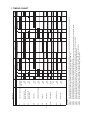
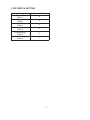
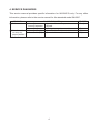
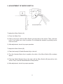
NO.
E1AH-806
ISSUED: MAY 8, 2010
REVISED:
HOSHIZAKI
SELF-CONTAINED CUBER
MODEL
IM-65LE-Q
SERVICE MANUAL
CONTENTS
PAGE
1. TIMING CHART-----------------------------------------------------------------------------------------1
2. WIRING DIAGRAM------------------------------------------------------------------------------------2
3. DIP SWITCH SETTING-------------------------------------------------------------------------------3
4. SERVICE DIAGNOSIS--------------------------------------------------------------------------------4
5. ADJUSTMENT OF MICRO SWITCH--------------------------------------------------------------5
This service manual provides specific information for IM-65LE-Q only. For any other
information, please refer to the service manual for the standard model IM-65LE.
i
1
ON
OFF
ON
OFF
Down
OFF
Up
After power supply is turned on or freeze cycle completes, FM starts, water plate opens to reach cam actuating position, and water supply begins for defrost cycle.
If water plate does not release ice after reaching cam actuating position, ACM and CM stop.
When water plate releases ice, WV closes and water plate starts to open further.
When water plate fully opens and S1 moves to left (arm down) position, HV opens. When 3 minutes passes after CM stops in [state 2], CM restarts.
Cube control thermistor senses temperature higher than defrost setting, water plate starts to close and water supply begins.
When water plate closes and S1 moves to right (arm up) position, water supply stops and PM starts.
When 15 seconds passes after S1 moves to right (arm up) position, FM starts and PM stops to start freezing.
When cube control thermistor senses temperature lower than freeze setting, [state 1] begins.
Defrost
4
5,6
7
th > defrost setting
Operation
State 1,2
State 3
State 4
State 5
State 6
State 7
State 8
State 9
3
Water Valve
1,2
WV
9
th < freeze setting
Freeze
Hot Gas Valve
ON
OFF
ON
OFF
8
15 sec
HV1
Fan Motor
FM
ON
OFF
Defrost
5,6
7
th > defrost setting
Actuator Motor
CM/PM Cut Off Relay
X5
ON
OFF
4
ACM
Compressor
CM
ON
OFF
3
Pump Motor
Micro Switch (B)
(Cam control)
S3
ON
OFF
1,2
PM
Micro Switch (A)
(Water Pan control)
Actuator Toggle Switch Left (Arm Down)
Right (Arm Up)
S2
S1
State
IM-65LE-Q
Freeze
8
15 sec
1. TIMING CHART
2. WIRING DIAGRAM
2
3. DIP SWITCH SETTING
Dip Switch No.
Freeze VR
DSW 1
Defrost VR
DSW 2
Dimple Range
DSW 3
Water Supply
DSW 4
Code Setting 1
DSW 5
Code Setting 2
DSW 6
Volume Setting
A
4
4
0
9
7
3
4. SERVICE DIAGNOSIS
This service manual provides specific information for IM-65LE-Q only. For any other
information, please refer to the service manual for the standard model IM-65LE.
PROBLEM
[1]Deformed ice.
[2]Cam Arm will
not stop at a
proper position.
a)Water Pan
Lower Evaporator
b)Lower Evaporator
a)Micro Switch (A)
b)Micro Switch (B)
POSSIBLE CAUSE
1.Upper and Lower Evaporators not
aligned.
1.Coating damaged, removed or worn.
1.Open circuit or moisture inside.
1.Open circuit or moisture inside.
4
REMEDY
1.Readjust.
1.Replace.
1.Replace.
1.Replace.
5. ADJUSTMENT OF MICRO SWITCH
Actuator Motor Arm
To adjust the Micro Switch (A):
1)Close the Water Pan.
2)Push up the lever until the Micro Switch (A) trips with a click sound. Then, push the
lever 1 mm further up to lock in position. Do not bend the actuator by pushing up the
lever too much.
3)After adjustment, check for proper operation.
To adjust the Micro Switch (B):
1)Push the loosely fit Switch Bracket fully to the left.
2)Turn the Actuator Motor Arm to position the roller of the Micro Switch (B) as shown
above.
3)Push the Switch Bracket fully to the right until the Micro Switch (B) trips with a click
sound. Then, lock the Switch Bracket in that position.
4)After adjustment, check for proper operation.
5