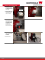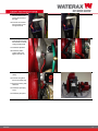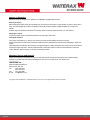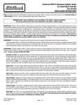
1
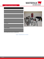
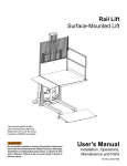
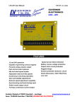
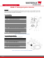
USER INSTRUCTIONS MARK-3® DIS Digital Ignition Solution Overview: ® WATERAX offers a conversion kit Digital Ignition Solution (DIS) for users that want to convert a MARK-3 from breaker points and mechanical cut-out switch to the upgraded electronic ignition and Digital Overspeed Switch systems. These instructions will guide you through the conversion process. Parts Breakdown: ID ITEM NO DESCRIPTION QTY - 600556 DIS MK-3 CONVERSION KIT UPG TO CDI / DOS 1 1 600125 B-7592 ELECTRONIC IGNITION BOX ASSY 1 2 701109 R-668E MAGNETO FOR 185CC 1 3 800073 R-661-CDI STATOR, COIL/ARMATURE ASSEMBLY 1 4 800544 R-150 NUT M6X1.0 HEX FUJI LOCK ZINC 1 5 800408 B-5562-18 CLAMP PLASTIC COATED 9/16" ID 1 6 700593 B-6289-1 DOS PRODUCTION UNIT 1 7 700616 B-6289-2 DOS MK-3 BRACKET 1 8 800443 B-6289-3 SCREW M4X0.7X35 PHILLIPS CHEESE HEAD ZINC 2 9 800402 B-6289-4 SCREW M4X0.7X8 PHILLIPS RAISED CHEESE ZINC 2 10 800413 B-6289-5 SCREW M4X0.7X8 PHILLIPS FLAT ZINC 1 11 800400 B-6289-6 LOCKWASHER M4 EXTERNAL TOOTH ZINC 4 - 801116 CABLE TIE 4" NYLON BLACK 3 - 701161 USER INST DIGITAL IGNITION SOLUTION DIS 1 Figure 1: Digital Ignition Solution (DIS) (600556) Tools and Materials Required: To complete the installation, you will require the following tools: ID ITEM NO DESCRIPTION QTY 1 600154 R-929 FLYWHEEL HOLDING TOOL, PLATED STEEL 1 2 701159 PISTON LOCKING TOOL FOR 185CC 1 3 700723 R-927 PULLER - MAGNETO (M38 X 1.5) 1 4 701158 JIG FOR DOS BRACKET DRILLING 1 5 801117 DRILL BIT #30 HIGH SPEED STEEL 2-3/4"LG 1 6 801118 TAP M4X.7 D4 SPRIAL POINT PLUG HIGH SPEED STEEL 1 7 801146 CDI IGNITION TIMING ADJUSTMENT TOOL 1 8 801162 DIS - FRAME DRILLING TOOL 1 Figure 2: Special tools for conversion (available from WATERAX) 03/2015 1 USER INSTRUCTIONS DESCRIPTION QTY TORQUE WRENCH 1 13 MM WRENCH 1 10 MM WRENCH 4 7/16” WRENCH 3 13 MM SOCKET 1 10 MM SOCKET 1 7/16” SOCKET 1 17 MM SOCKET 1 RATCHET WRENCH 1 CUTTER 1 FLAT SCREWDRIVER 1 PHILLIPS SCREWDRIVER 1 NEEDLE NOSE PLIERS 1 17/64” DRILL BIT 1 VARIABLE SPEED ELECTRIC DRILL 1 M4X0.7 TAP 1 #30 DRILL BIT TAPPING LUBRICANT 1 PENCIL OR MARKER (IF NOT EQUIPPED WITH DOS DRILLING JIG) 1 CENTER PUNCH (IF NOT EQUIPPED WITH DOS DRILLING JIG) 1 THREAD LOCKER LOCTITE 243 OR EQUIVALENT - RTV SILICONE SEALANT LOCTITE 5910 OR EQUIVALENT - Figure 3: Required tools for conversion 03/2015 2 USER INSTRUCTIONS Procedures: 1. Remove the 12-16 pump end. 2. Remove the fuel connection and disconnect the fuel line from the carburetor. 3. On the carburetor, rotate the fuel strainer cover by 180 degrees from position A to B (see picture). Position A Position B 4. Remove the frame. 5. Use the Drilling Jig to drill two 17/64” holes on the right leg (see images). If not equipped with tool use the hole pattern provided. The CDI box assembly will be mounted on the left and the fuel connection will move to the right. 6. Remove the ON/OFF switch and disconnect the cut-out switch wire. Discard. 7. Remove the ignition cable clamp (#10). 8. Remove the fan cowl. 9. Uninstall and discard the mechanical cut-out switch and grommets. 10.Remove the pulley and gasket. 11.If equipped with an aluminum fan, use the fan/flywheel holding tool R-929 and remove the nut (R-303) that locks the flywheel assembly onto the crankshaft. 03/2015 3 USER INSTRUCTIONS 12.Using the fan/flywheel holding tool (R-929), the flywheel assembly puller (R-927) and an adjustable wrench, remove the flywheel assembly. 13.NOTE: If equipped with a thermoplastic fan, use piston locking tool 701159 instead of R929. Screw tool onto the cylinder head and rotate crankshaft until the piston reaches the tip to lock the shaft rotation. 701159 can be used with both fans. 14.Remove the point magneto by removing the three nuts. Discard. If the magneto is stuck on the backing plate, it can be pried off with a soft hammer and a flat screw driver. Be careful not to damage the fan. Nuts (3X) Point magneto New magneto for CDI 15.Install the new magneto for CDI using thread locker Loctite 243 or equivalent. Tightening torque for the three nuts: 8-10 Nm. Loctite 243 16.Remove the point stator assembly and replace with the CDI stator assembly. Discard point stator. 17.To position the stator, remove labyrinth ring and install ignition timing adjustment tool 801146. Turn stator clockwise until coil rests on adjustment tool. Tighten the three screws with flat and lock washers. 03/2015 Point stator assembly CDI stator assembly 4 USER INSTRUCTIONS Tightening torque: 2.53 Nm. Be careful not to squeeze/pinch the green wire. 18.If you are not equipped with the timing adjustment tool, fit the stator plate so that the oblong holes are centered with the crankcase threaded holes; then rotate the stator plate 1-1.5 mm counter-clockwise and tighten the three screws. Refer to the MK-3 Service Manual for dynamic ignition verification procedures Timing adjustment tool Coil resting on tool . Stator plate adjustment, 1-1.5 mm CCW 19.First pass the green wire through the crankcase hole and then through the grommet. Install the grommet on the crankcase. 20.Pull the green wire through the grommet and apply a dab of RTV silicone sealant. 21.Install the flywheel assembly. Ensure that the key is properly installed. Apply Loctite 243 on the hex nut (R303) and tighten using the fan/flywheel holding tool (R-929). Tightening torque: 4550 Nm. 22.Install the gasket pulley and pulley. 03/2015 5 USER INSTRUCTIONS 23.To install the DOS, three holes will need to be drilled and tapped on the side of the fan cowl. 24.If you’re using the DOS bracket drilling jig, install it on the top 8 mm hole and lock it in place. Drill the three holes with a #30 drill bit. 8 mm hole Fan cowl before drilling of 3 holes Drilling jig 25.Carefully tap all three holes with an M4x0.7 tap. Important: use tapping lubricant. Tapping lubricant 26.If you are not equipped with the drilling jig, you can use the bracket to position the holes. To correctly position the bracket and prevent any interference, install the DOS on the bracket. Position the assembly on the side of fan cowl and ensure that: There is no interference with the carburetor shroud; There is no interference with the spark plug cover; The bracket lays flat on the fan cowl (be careful of the radius on the fan cowl). 27.Mark the holes with a center punch. 28.Remove the fan cowl. Drill and tap. 03/2015 6 USER INSTRUCTIONS 29.Install the fan cowl. Do not install the top lock nut, air filter side. It will be used as a ground at a later step. Grounding stud 30.Install the DOS bracket using the three 8 mm long screws and two tooth lock washers. 31.Install the DOS using the two 35 mm long screws and two tooth lock washers. Ensure that the DOS is firmly mounted on the bracket to ensure proper ground contact. 32.Install the electronic ignition box assembly and the fuel connection. 33.Install the frame. 03/2015 7 USER INSTRUCTIONS 34.Connect the green wire from the stator in the second terminal from the right. 35.Connect the red wire from the DOS on the far right terminal. 36.Install the ground wire (red) coming from the CDI module on the fan cowl grounding stud. 37.Install the split loom. 38.Install the plastic coated clamp and tighten the lock nut. 39.Install the ignition cable clamp. 40.Connect the ignition wire to the spark plug. 41.Secure the wiring with cable ties. 42.Install the spark plug cover. 43.Install the pump end. 03/2015 8 USER INSTRUCTIONS Impact on Field Use: ® Below are the minor changes to the operation of the MARK-3 equipped with the DOS. Starting the engine: Before starting the engine, slowly pull the starter rope and crank over the engine a couple of times in order to charge up the DOS. The LED will light up and flash to indicate that the DOS has been charged and that the MARK-3® is ready to be started. Start the engine as directed in the MARK-3® Instruction & Service manual. (Note that there is no “ON” switch). Stopping the engine: To stop the engine, press and hold the OFF button until the engine shuts down. Overspeed condition: If the engine overspeeds (e.g., during a loss of prime), the DOS will immediately shut down the engine. Always ensure that the cause of the overspeed condition has been identified and corrected before attempting to restart the engine. When attempting to restart the engine (after an overspeed condition or after pressing the OFF button), wait 10 seconds from the time the engine shut down. This will enable the DOS to reset itself. Failure to wait the prescribe duration of time will make it difficult to start the engine. It may lead to a flooding condition. Warranty, Service and Support: Product and service documentation such as tech notes, data sheets, manuals and information on the limited warranty provided on products manufactured by WATERAX can be found on our Web site at: www.waterax.com. WATERAX Inc. 6635 Henri-Bourassa Blvd. W. Montreal, QC, H4R 1E1 Tel.: (855) 616-1818 (514) 637-1818 Fax: (514) 637-3985 E-mail: [email protected] Copyright © 2015 WATERAX Inc. Publication Number: 701161, Rev.6 All rights reserved. Printed in Canada. 03/2015 9