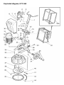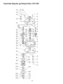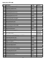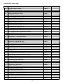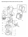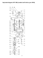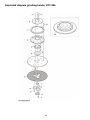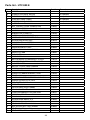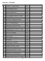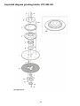
1
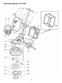
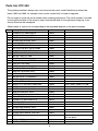
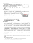
HTC SWEDEN AB
www.htc-sweden.com
GB
Service Manual
HTC 500, 650 & 800
Introduction
Contact HTC or your nearest reseller if you have questions or comments. Make sure to have the
serial number of your machine available when you call, since all machines are registered and this
helps us provide you with the best possible service. The serial number is located on the righthand side of the chassis (seen from behind) and on the right-hand fixing lug. It is also found on
the machine sign located on the electrical housing
It is possible to read the manufacture date of the machine from the serial number. In the example
of 89704240, 8 represents the model - this is an HTC 800. The next six numbers are the date of
manufacture. The last number is a sequence number and 0 indicates that this is the first machine
built on this day.
Best wishes!
HTC Sweden AB
3
CONTENTS
Introduction ........................................................................................................................... 3
Technical data HTC 500, HTC 650 and HTC 800 ................................................................ 5
Exploded diagram, HTC 500 ................................................................................................ 6
Exploded diagram, HTC 500 ................................................................................................ 7
Parts list, HTC 500 ............................................................................................................... 8
Exploded diagram, HTC 650 .............................................................................................. 11
Exploded diagram grinding holder, HTC 650...................................................................... 12
Parts list, HTC 650 ............................................................................................................. 13
Parts list, HTC 650 ............................................................................................................. 14
Parts list, HTC 650 ............................................................................................................. 15
Exploded diagram HTC 800 (models built before year 2000) ............................................. 16
Parts list HTC 800 (models built before year 2000) ............................................................ 18
Exploded diagram - HTC 800 E.......................................................................................... 21
Parts list - HTC 800 E ......................................................................................................... 25
Exploded diagram - HTC 800 HD ....................................................................................... 29
Parts list - HTC 800 HD ...................................................................................................... 33
Changing the inner belt, HTC 500/650/800 ........................................................................ 37
Changing the upper belt, HTC 500 ..................................................................................... 41
Changing the upper belt, HTC 650/800 .............................................................................. 42
Overhauling the grinding holders........................................................................................ 43
Maintenance ....................................................................................................................... 45
Troubleshooting .................................................................................................................. 46
Electronic error codes - Hitachi .......................................................................................... 47
Checking the latest error code - Hitachi ............................................................................. 48
Special tools ....................................................................................................................... 49
4
Technical data HTC 500, HTC 650 and HTC 800
HTC 500
HTC 650
HTC 800
Model:
HTC 502E
HTC 504E
HTC 504S
Motor output
2.2 kW
4.0 kW
4.0 kW
Current:
10 Amp
16 Amp
16 Amp
Voltage:
220 V
3x380 V
3x380 V
Weight:
120 kg
140 kg
120 kg
Grinder diameter:
500 mm
500 mm
500 mm
Grinding pressure:
100 kg
120 kg
100 kg
Revolutions per
minute:
300-1300 rpm
300-1300 rpm
750 rpm
Water tank
(volume):
17 l
17 l
17 l
Grinding wheels:
3x220 mm
3x220 mm
3x220 mm
Model:
HTC 650E
HTC 650S
Motor output:
7.5 kW
5.5 kW
Current:
16 Amp
16 Amp
Voltage:
3x380 V
3x380 V
Weight:
240 kg
220 kg
Grinder diameter:
650 mm
650 mm
Grinding pressure:
210 kg
190 kg
Revolutions per
minute:
300-1300 rpm
750 rpm
Water tank
(volume):
40 l
40 l
Grinding wheels:
3x220 mm
3x220 mm
Model:
HTC 800HD
HTC 800E
Motor output:
11 kW
7.5 kW
Current:
25 Amp
16 Amp
Voltage:
3x380 V
3x380 V
Weight:
315-370 kg
280 kg
Grinder diameter:
800 mm
800 mm
Grinding pressure:
280-335 kg
240 kg
Revolutions per
minute:
300-1300 rpm
300-1300 rpm
Water tank
(volume):
40 l
40 l
Grinding wheels:
3x270 mm
3x270 mm
5
Exploded diagram, HTC 500
6
Exploded diagram, HTC 500
7
Parts list, HTC 500
The grinding machine’s design may vary based on the year’s model. Machines produced between 1992 and 1995, for example, have a drive system that is simple to upgrade.
Do not forget to quote the serial number when ordering spare parts. The serial number is located
on the right-hand side of the chassis (seen from behind) and on the right-hand fixing lug. It can
also be found on the nameplate.
Shown below is a parts list corresponding to the exploded diagram on the previous pages.
Pos.
Description
Part No.
1
CHASSIS HTC 500 HANDLE
110616
2
CHASSIS HTC 500 POST
110618
3
SCREW M6S M8X25 GALV
310001
4
SCREW M6S M12X85 GALV
310002
5
WASHER BRB M12 GALV
310003
6
WASHER BRB M12 GALV
310003
7
NUT NYLOCK M12 GALV DIN985
310004
8
SPRINT CHASSIS HTC 500
110001
9
SCREW MC6S M8X10 8.8 GALV
310006
10
WATER TANK HTC 500
110002
11
COVER, WATER TANK
Discontinued
12
FREQUENCY CONVERTER
11 different models According to specification
12a
PROTECTIVE CAGE
110385
13
SCREW M6S M10X35 GALV
310007
14
CHASSIS HTC 500 BOTTOM
110617
15
WASHER TBRB M10 GALV
310008
16
NUT NYLOCK M10 GALV DIN985
310009
17
WATER VALVE TO GRINDER
110007
18
SCREW M6S M5X20 GALV
310010
19
WHEEL FITTING KIT
110008
20
WHEEL HTC 650 WKCP 2803 6553
110350
21
MOTOR
4 different models
22
SCREW M6S M12X25 GALV
310011
23
WASHER BRB M12 GALV
310003
24
SCREW MC6S M6X10 8.8 GALV
310005
25
WASHER BRB M6 GALV
310012
26
COVER HTC 500 COMPLETE
110142
27
FIXING LUG
110013
28
WASHER BRB M12 GALV
310003
29
SCREW M6S M10X35 GALV
310007
30
SPLIT PLATE
110014
31
SCREW MF6S M6X20 10.9 GALV
310013
32
BELT RING
Discontinued
33
BELT, UPPER S-140 HTC 500
110016
34
SCREW MFT-TT M6X16 8.8 GALV
310014
8
Remarks
New tank without cover
also 110381, wheel HTC 500
The motor plate and the belt ring
are one piece
Parts list, HTC 500
Pos.
Description
Part No.
35
MOTOR PLATE HTC 500
110017
36
SCREW M6S M8X25 GALV
310001
37
WASHER TBRSB M8 GALV
310015
38
CIRCLIP SGA 20
310016
39
SHAFT BELT TENSIONER
110018
40
BALL BEARING 6005-2RS C3
110019
41
TENSIONING WHEEL HTC 500
110020
42
BELT, INNER S-250 HTC 500
110021
43
BALL BEARING 6005-2RS C3
110019
44
CIRCLIP SGA 20
310016
45
SCREW MFT-TT M6X16 8.8 GALV
310014
46
UPPER COVER HTC 500
110022
47
FIXING BOSS, NON-ZINC
110023
48
SCREW MFT-TT M6X25 8.8 GALV
310025
49
BEARING CUP, TOP CENTRE HTC 500
110024
50
BALL BEARING 6012-2RS C3
110026
51
BEARING CUP, BOTTOM CENTRE 500
110027
52
CIRCLIP SGA 60
310018
53
CENTRE HUB
110030
54
BALL BEARING 6205 2RS C3
110031
55
BEARING CUP PULLEY UPPER HTC
500
110032
56
FIXING BOSS, NON-ZINC
110023
57
SCREW MFT-TT M6X16 8.8 GALV
310014
58
SCREW MFT-TT M6X16 8.8 GALV
310014
59
SPACER 6205
110033
60
SCREW MC6S M10X60 12,9
310019
61
COVER, CENTRE HUB HTC 500
110034
62
SCREW MFT-TT M6X25 8.8 GALV
310025
63
SCREW M6S M8X25 GALV
310001
64
WASHER TBRSB M8 GALV
310015
65
SHAFT BELT TENSIONER
110018
66
SCREW MFT-TT M6X25 8.8 GALV
310025
67
CIRCLIP SGA 20
Discontinued
68
GAMMA RING RB 20X35X4
110564
69
SHAFT COVER
110036
70
SPACER 6205
110033
71
BALL BEARING 6205 2RS C3
110031
72
BEARING CUP PULLEY UPPER HTC
500
110032
73
CIRCLIP SGA 25
310021
74
--------
75
--------
76
--------
9
Remarks
Gamma ring is used instead
Parts list, HTC 500
Pos.
Description
Part No.
77
SHAFT, PULLEY
110039
78
WEDGE RK 8X7X25 H9
310023
79
WEDGE RK 8X7X25 H9
310023
80
PULLEY HTC 500 32X150
110040
81
--------
82
--------
83
--------
84
CIRCLIP SGA 25
85
BEARING CUP PULLEY LOWER HTC500 110041
86
CIRCLIP SGA 50
310024
87
BALL BEARING 6010 2RS C3
110044
88
PULLEY HUB HTC 500
110045
89
EDGING STRIP HTC 500
110046
90
LOWER COVER HTC 500
110047
91
SPACER 6010
110048
92
HUB COVER HTC 500
110049
93
SCREW MFT-TT M6X25 8.8 GALV
310025
94
CYLINDER PIN CP 6X20 H8
310046
95
CIRCLIP SGA 60
310018
96
SGRINDING HOLDER UPPER HTC 500
110050
97
HOLDER, POLYCORD, OUTER
110051
98
SCREW MC6S M6X16 8.8 GALV
310082
99
PAD, POLYCORD GREEN 168MM
110370
100
HOLDER, POLYCORD INNER
110386
101
SCREW MFT-TT M6X16 8.8 GALV
310014
102
SPRING
110052
103
GRINDING HOLDER, LOWER, HTC 500
110053
104
SCREW
310027
105
CROSS-PIECE PART 3
110054
106
CROSS-PIECE PART 1 M6
110055
107
SCREW MC6S M6X20 12.9
310027
108
CROSS-PIECE PART 2
110056
109
SCREW MF6S M5X8 GALV
310028
Remarks
310021
10
2 per grinding holder
Exploded diagram, HTC 650
11
Exploded diagram grinding holder, HTC 650
12
Parts list, HTC 650
Pos.
Description
Part No.
1
CHASSIS HTC 650/800 HANDLE
110057
2
CONSOLE CONTROL PANEL
110058
3
SCREW RXS B10X16 GALV
310029
4
SCREW MC6S M6X12 8.8 GALV
310030
5
WASHER BRB M6 GALV
310012
6
WIRING HOLDER (CLIP) JR12
110059
7
WASHER BRB M6 GALV
310012
8
SCREW MC6S M6X12 8.8 GALV
310030
9
WIRING HOLDER (CLIP) JR12
110059
10
WASHER BRB M6 GALV
310012
11
SCREW MC6S M6X12 8.8 GALV
310030
12
CHASSIS HTC 650/800 POST
110060
13
SCREW M6S M16X120 GALV
310031
14
WASHER BRB M16 GALV
310032
15
SPRINT CHASSIS HTC 650/800
110061
16
WASHER BRB M16 GALV
310032
17
NUT NYLOCK M16 GALV DIN985
310033
18
SCREW MF6S M8X25 GALV
310071
19
TANK BRACKET
110062
20
WASHER BRB M6 GALV
310012
21
SCREW MC6S M6X12 8.8 GALV
310030
22
FREQUENCY CONVERTER 7.5 kw
According to
specification
22
SOFT START 5.5 kw
According to
specification
22a
PROTECTIVE CAGE FREQUENCY CONVERTER
110158
22a
PROTECTIVE CAGE SOFT START
110003
23
SCREW M6S M12X65 GALV
310034
24
NUT NYLOCK M12 GALV DIN985
310004
25
CHASSIS HTC 650 BOTTOM
110643
26
WHEEL FITTING KIT
110008
27
WHEEL HTC 650 WKCP 2803 6553
110350
28
WATER VALVE TO GRINDER
110007
29
SCREW M6S M5X20 GALV
310010
30
WATER TANK HTC 650/800
110069
31
MOTOR 7.5 DPIG 132M-4 200/346
110226
31
MOTOR 5.5KW DPIG132S-4,400/690
110368
31
MOTOR 5.5KW DPIG132S-4 200/400
110312
32
SCREW M6S M12X25 GALV
310011
33
WASHER BRB M12 GALV
310003
34
SCREW MC6S M6X25 12.9 GALV
310035
35
WASHER BRB M6 GALV
310012
36
COVER HTC 650 COMPLETE
110121
37
FIXING LUG
110072
13
Remarks
Parts list, HTC 650
Pos.
Description
Part No.
38
MOTOR PLATE HTC 650
110073
39
SCREW MC6S M8X25 12.9
310036
40
WASHER BRB M12 GALV
310003
41
SCREW M6S M12X45 GALV
310037
42
BELT RING HTC 650
110074
43
BELT, UPPER S-140 HTC 650
110075
44
SCREW MFT-TT M6X16 8.8 GALV
310014
45
SCREW M6S M10X25 GALV
310114
46
WASHER TBRSB M10 GALV
310042
47
CIRCLIP SGA 35
310038
48
SHAFT BELT TENSIONER
110077
49
BALL BEARING 6207 2RS C3
110078
50
TENSIONING WHEEL HTC 650
110079
51
BELT, INNER S-250 HTC 650
110080
51
BELT, INNER S-250 HTC 650 SOFT START
110376
52
BALL BEARING 6207 2RS C3
110078
53
CIRCLIP SGA 35
310038
54
SCREW MFT-TT M6X16 8.8 GALV
310014
55
FIXING BOSS, NON-GALV
110023
56
UPPER COVER HTC 650
110081
57
SCREW MFT M6X30 8.8 GALV
310017
58
BEARING CUP TOP, CENTRE HTC650
110082
59
BALL BEARING 6214-2RS1
110083
60
BEARING CUP, BOTTOM CENTRE 650
110084
61
CIRCLIP SGA 70
310040
62
CENTRE HUB
110085
62
CENTRE HUB SOFT START
110159
63
BALL BEARING 6207 2RS C3
110078
64
BEARING CUP PULLEY UPPER HTC 650
110086
65
EDGING STRIP HTC 650
110087
66
SPACER 6207
110088
67
SCREW MC6S M12X60 12,9
310041
68
COVER, CENTRE HUB HTC 650/800
110089
69
SCREW MFT-TT M6X25 8.8 GALV
310025
70
FIXING BOSS, NON-ZINC
110023
71
SCREW MFT-TT M6X16 8.8 GALV
310014
72
SCREW M6S M10X25 GALV
310114
73
WASHER TBRSB M10 GALV
310042
74
COUNTERWEIGHT HTC 650/800
110090
75
SCREW MFT-TT M6X25 8.8 GALV
310025
76
CIRCLIPSGA 25
310021
77
--------
78
SHAFT COVER
110092
14
Remarks
Parts list, HTC 650
Pos.
Description
Part No.
79
--------
80
BALL BEARING 6207 2RS C3
110078
81
BEARING CUP PULLEY UPPER HTC 650
110086
82
CIRCLIP SGA 40
310043
83
SHAFT, PULLEY
110093
84
WEDGE RK 12X8X40
310044
85
WEDGE RK 12X8X30
310045
86
PULLEY HTC 650 50X180
110118
87
CIRCLIP SGA 40
310043
88
BEARING CUP PULLEY LOWER HTC650
110094
89
CIRCLIP SGA 60
310018
90
BALL BEARING 6012 2RS C3
110026
91
PULLEY HUB HTC 650
110095
92
LOWER COVER HTC 650
110096
93
SCREW MFT-TT M6X16 8.8 GALV
310014
94
HUB COVER (PROCESSING) HTC 650(/800)
110097
95
SCREW MFT M6X30 8.8 GALV
310017
96
CIRCLIP SGA 70
310040
97
GRINDING HOLDER UPPER HTC 650/800
110098
98
CYLINDER PIN CP 6X20 H8
310046
99
HOLDER, POLYCORD, OUTER
110099
100
SCREW MC6S M6X16 8.8 GALV
310082
101a PAD, POLYCORD BLACK 184MM
110371
101b PAD, POLYCORD GREEN 184MM
110369
101c PAD, POLYCORD GREEN 184MM
110369
102
HOLDER, POLYCORD INNER
110397
103
SCREW MFT-TT M6X16 8.8 GALV
310014
104
SPRING
110100
105
GRINDING HOLDER, LOWER, HTC 650
110101
106
SCREW MC6S M6X20 12.9
310027
107
CROSS-PIECE PART 3
110054
108
CROSS-PIECE PART 1 M8
110257
109
SCREW MFT M8X16 8.8 GALV
310070
110
CROSS-PIECE PART 2
110056
111
SCREW MF6S M5X8 GALV
310028
15
Remarks
Exploded diagram HTC 800 (models built before year 2000)
16
Exploded diagram HTC 800 (models built before year 2000)
17
Parts list HTC 800 (models built before year 2000)
Pos.
Description
Art.No:
Remarks
1
CHASSIS HTC 650/800 HANDLE
110057
2
CONSOLE CONTROL PANEL
110058
3
SCREW RXS B10X16 GALV
310029
4
SCREW MC6S M6X12 8.8 GALV
310030
5
WASHER BRB M6 GALV
310012
6
WIRING HOLDER (CLIP) JR12
110059
7
WASHER BRB M6 GALV
310012
8
SCREW MC6S M6X12 8.8 GALV
310030
9
WIRING HOLDER (CLIP) JR12
110059
10
WASHER BRB M6 GALV
310012
11
SCREW MC6S M6X12 8.8 GALV
310030
12
CHASSIS HTC 650/800 POST
110060
13
SCREW M6S M16X120 GALV
310031
14
WASHER BRB M16 GALV
310032
15
SPRINT CHASSIS HTC 650/800
110061
16
WASHER BRB M16 GALV
310032
17
NUT NYLOCK M16 GALV DIN985
310033
18
SCREW MF6S M8X25 GALV
310071
19
TANK BRACKET
110062
20
WASHER BRB M6 GALV
310012
21
SCREW MC6S M6X12 8.8 GALV
310030
22
FREQUENCY CONVERTER 7.5 kw
22a
PROTECTIVE CAGE
110158
23
SCREW M6S M12X65 GALV
310034
24
NUT NYLOCK M12 GALV DIN985
310004
25
CHASSIS HTC 800 BOTTOM
110619
26
WHEEL FITTING KIT
110008
Only for use with solid
wheels
27
WHEEL HTC 800
110382
More alternatives
available
28
WATER VALVE TO GRINDER
110007
29
SCREW M6S M5X20 GALV
310010
30
WATER TANK HTC 650/800
110069
31
MOTOR 7.5 DPIG 132M-4 200/346
110226
32
SCREW M6S M12X25 GALV
310011
33
WASHER BRB M12 GALV
310003
34
SCREW MC6S M6X25 12.9 GALV
310035
35
WASHER BRB M6 GALV
310012
36
COVER HTC 800 COMPLETE NEW RIGHT
110228
37
FIXING LUG
110072
38
MOTOR PLATE HTC 800
110104
39
SCREW MC6S M8X25 12.9
310036
40
WASHER BRB M12 GALV
310003
According to specification
18
More alternatives
available
Parts list HTC 800 (models built before year 2000)
Pos.
Description
Art.No:
41
SCREW M6S M12X45 GALV
310037
42
BELT RING HTC 800
110105
43
BELT, UPPER S-140 HTC 800
110106
44
SCREW MFT-TT M6X16 8.8 GALV
310014
45
SCREW M6S M10X25 GALV
310114
46
WASHER TBRSB M10 GALV
310042
47
CIRCLIP SGA 35
310038
48
SHAFT BELT TENSIONER
110077
49
BALL BEARING 6207 2RS C3
110078
50
TENSIONING WHEEL HTC 650
110079
51
BELT, INNER, HTC 800 OLD MODEL
110107
52
BALL BEARING 6207 2RS C3
110078
53
CIRCLIP SGA 35
310038
54
SCREW MFT-TT M6X16 8.8 GALV
310014
55
FIXING BOSS, NON-ZINC
110023
56
UPPER COVER HTC 800
110108
57
SCREW MFT M6X30 8.8 GALV
310017
58
BEARING CUP TOP, CENTRE HTC650
110082
59
BALL BEARING 6214-2RS1
110083
60
BEARING CUP, BOTTOM CENTRE 650
110084
61
CIRCLIP SGA 70
310040
62
CENTRE HUB
110085
63
BALL BEARING 6207 2RS C3
110078
64
BEARING CUP PULLEY UPPER HTC 650
110086
65
EDGING STRIP HTC 650
110087
66
SPACER 6207
110088
67
SCREW MC6S M12X60 12.9
310041
68
COVER, CENTRE HUB HTC 650/800
110089
69
SCREW MFT-TT M6X25 8.8 GALV
310025
70
FIXING BOSS, NON-ZINC
110023
71
SCREW MFT-TT M6X16 8.8 GALV
310014
72
SCREW M6S M10X25 GALV
310114
73
WASHER TBRSB M10 GALV
310042
74
COUNTERWEIGHT HTC 650/800
110090
75
SCREW MFT-TT M6X25 8.8 GALV
310025
76
CIRCLIP SGA 25
310021
77
--------
78
SHAFT COVER
79
--------
80
BALL BEARING 6207 2RS C3
110078
81
BEARING CUP PULLEY UPPER HTC 650
110086
82
CIRCLIP SGA 40
310043
83
SHAFT, PULLEY
110093
110092
19
Remarks
Parts list HTC 800 (models built before year 2000)
Pos.
Description
Art.No:
84
WEDGE RK 12X8X40
310044
85
WEDGE RK 12X8X30
310045
86
PULLEY HTC 650 50X180
110118
87
CIRCLIP SGA 40
310043
88
BEARING CUP PULLEY LOWER HTC650
110094
89
CIRCLIP SGA 60
310018
90
BALL BEARING 6012 2RS C3
110026
91
PULLEY HUB HTC 650
110095
92
LOWER COVER HTC 800
110110
93
SCREW MFT-TT M6X16 8.8 GALV
310014
94
HUB COVER (PROCESSING) HTC 650(/800)
110097
95
SCREW MFT M6X30 8.8 GALV
310017
96
CIRCLIP SGA 70
310040
97
GRINDING HOLDER UPPER HTC 650/800
110098
98
CYLINDER PIN CP 6X20 H8
310046
99
HOLDER, POLYCORD, OUTER
110099
100
SCREW MC6S M6X16 8.8 GALV
310082
101a
RONDELLPAD, POLYCORD BLACK 184MM
110371
101b
PAD, POLYCORD GREEN 184MM
110369
101c
PAD, POLYCORD GREEN 184MM
110369
102
HOLDER, POLYCORD INNER
110397
103
SCREW MFT-TT M6X16 8.8 GALV
310014
104
SPRING
110100
105
GRINDING HOLDER, LOWER, HTC 800
110111
106
SCREW MC6S M6X20 12.9
310027
107
CROSS-PIECE PART 3
110054
108
CROSS-PIECE PART 1 M8
110257
109
SCREW MFT M8X16 8.8 GALV
310070
110
CROSS-PIECE PART 2
110056
111
SCREW MF6S M5X8 GALV
310028
20
Remarks
Exploded diagram - HTC 800 E
21
Exploded diagram - HTC 800 E
22
Exploded diagram - HTC 800 E
23
Exploded diagram grinding holder, HTC 800
24
Parts list - HTC 800 E
Pos.
Description
Part No.
1
CHASSIS HTC 650/800 HANDLE
110057
1A
SHRINK TUBING TO HTC HANDLE
110308
2
COVER PLUG TO HTC HANDLE
110357
3
CONSOLE CONTROL PANEL
110058
4
SCREW RXS B10X16 GALV
310029
5
CONTROL PANEL, COMPLETE
110122
5A
EMERGENCY STOP, COMPLETE XB4
110481
5B
POTENTIOMETER COMPLETE
110500
5C
ON/OFF KNOB, COMPLETE
110499
5D
LAMP, GREEN
110491
5E
RESET BUTTON COMPLETE
110498
5F
FRONT/BACK KNOB, COMPLETE
110485
6
SCREW MC6S M6X12 8.8 GALV
310030
7
WASHER BRB M6 GALV
310012
8
SCREW MC6S M6X12 8.8 GALV
310030
9
WASHER BRB M6 GALV
310012
10
WIRING HOLDER (CLIP) JR12
110059
11
SCREW MC6S M6X12 8.8 GALV
310030
12
WASHER BRB M6 GALV
310012
13
WIRING HOLDER (CLIP) JR12
110059
14
CHASSIS HTC 650/800 POST
110060
15
SCREW M6S M16X120 GALV
310031
16
WASHER BRB M16 GALV
310032
17
NUT NYLOCK M16 GALV DIN985
310033
18
WASHER BRB M16 GALV
310032
19
SPRINT CHASSIS HTC 650/800
110061
20
HAIR PIN, GALV 3.5X75
310125
21
SCREW MC6S M6X12 8.8 GALV
310030
22
WASHER BRB M6 GALV
310012
23
TANK BRACKET
110062
24
FREQUENCY CONVERTER 7.5 kW
24A
RUNNING TIME METRE CURTIS
110309
25
CHASSIS HTC 650/800 PROTECTIVE CAGE
110158
26
SCREW MF6S M8X25 GALV
310071
27
WALL SOCKET 16A 200-250V 3P BLUE
110534
28
SCREW M6S M5X20 GALV
310010
29
WALL INLET 16A 346-415V 5P RED
30
PHASE INDICATOR 4 DIODES 16A 400 VOLTS
110229
PHASE INDICATOR 3 DIODES 200V
110344
31
SCREW M6S M5X20 GALV
310010
32
WASHER BRB M5 GALV
310194
33
NUT M6M M5 GALV
310193
34
CONNECTOR, FEMALE, MOTOR
Remarks
as specified
as specified
as specified
25
Parts list - HTC 800 E
Pos.
Description
Part No.
Remarks
35
SCREW
not available
36
CONNECTOR, MALE, MOTOR
as specified
37
ELECTRICAL CABLE, MOTOR
as specified
38
CONTROL PANEL CABLE
as specified
39
CONTROL PANEL CABLE
as specified
40
WATER TANK HTC 650/800
110069
41
NUT 1253-3/8 (T-HOSE CONNECTOR)
110332
42
HOSE CONNECTOR 2601-12-3/8
110147
43
HOSE CONNECTOR 2601-12-1/4
110205
44
ELBOW-PIPE-IU 2020-1/4
110146
45
WATER VALVE TO GRINDER
110007
46
HOSE LARGE REINFORCED PVC
110130
47
SCREW M6S M5X20 GALV
310010
48
CHASSIS HTC 800 BOTTOM
110619
49
SCREW M6S M12X65 GALV
310034
50
WASHER BRB M12 GALV
310003
51
NUT NYLOCK M12 GALV DIN985
310004
52
WHEEL HTC 800
110382
53
CAP, WHEEL
54
CIRCLIP SGA 20
310016
55
BALL BEARING HTC800 WHEEL, OUTER
110279
56
BALL BEARING HTC800 WHEEL, INNER
110278
57
GASKET, WHEEL
58
MOTOR 7.5 DPIG 132M-4 200/346
110226
59
SCREW M6S M12X25 GALV
310011
60
WASHER BRB M12 GALV
310003
61
COVER HTC 800 NEW MODEL, HIGH
110133
62
T-PIPE 10MM
110144
63
HOSE, POLYURETHANE TUBE 10/7 BLACK
110145
64
WIRING HOLDER (CLIP) JR14
110359
65
POP RIVET 4.8X12.7
310084
66
PIPE, PEH 50 LK
110383
67
VELCRO MALE WIDTH 38MM
110264
68
SPLASHGUARD HTC 800 3MX60MM
110114
69
FOAM 25X2500X20 ETHAFOAM 220E
110241
70
MOTOR PLATE HTC 800 NEW M132
110153
71
FIXING LUG
110072
72
SCREW MC6S M8X25 12,9
310036
73
SCREW M6S M12X45 GALV
310037
74
BRICWASHER BRB M12 GALV
310003
75
NUT NYLOCK M12 GALV DIN985
310004
76
BELT RING HTC 800 NEW
110143
77
BELT, UPPER, HTC 800 NEW MODEL
110126
not available
not available
26
Parts list - HTC 800 E
Pos.
Description
Part No.
78
SCREW MFT-TT M6X16 8.8 GALV
310014
79
BEARING CUP MOTOR PLATE HTC 800
110151
80
BALL BEARING 6314-2RS C3
110174
81
UPPER COVER HTC 800 (NEW)
110325
82
SCREW MC6S M8X16 GALV 8.8
310080
83
WASHER TBRSB M10 GALV
310042
84
SCREW MF6S M10X20
310078
85
TENSIONING WHEEL, COMPLETE, HTC 800
110568
86
PULLEY ASSEMBLY, COMPLETE, HTC 800
110567
86A
SHAFT JOURNAL
110318
86B
VR SEAL 4030-25A
110531
86C
RADIAL SEAL CR20X35X7 HMSA 10RG
110291
86D
BEARING CUP, UPPER, HTC 800/650 NEW
110296
86E
BALL BEARING 6312-2RS1/C3 HT
110289
86F
PULLEY HTC 800 NEW MODEL
110295
86G
BEARING CUP, LOWER, HTC 800/650 NEW
110297
86H
RADIAL SEAL CR 60X75X8 HMSA7 R
110290
86I
SCREW MC6S M8X60 12.9
310076
87
COUNTERWEIGHT HTC 650/800 NEW
110315
88
TENSIONING WHEEL, COMPLETE, HTC 800
110568
88A
SCREW MF6S M10X20
310078
88B
WASHER TBRSB M10 GALV
310042
88C
SHAFT BELT TENSIONER
110317
88D
BALL BEARING 6207 2RS C3
110078
88E
TENSIONING WHEEL HTC 800/650 NEW
110316
88F
CIRCLIP SGA 35
310038
89
SCREW MF6S M8X25 GALV
310071
90
BELT, INNER HTC 800 NEW 7.5KW
110288
91
CENTRE HUB
110293
92
BALL BEARING 6207 2RS C3
110078
93
EDGING STRIP HTC 800 NEW
110326
94
FIXING BOSS
110314
95
SCREW MFT-TT M6X16 8.8 GALV
310014
96
BEARING CUP CENTRE HTC 800
110140
97
LOWER COVER HTC 800 NEW
110324
98
SCREW MC6S M8X16 GALV 8.8
310080
99
COVER, INSPECTION HOLE, HTC 800
110141
100
SCREW M6S M5X10
310052
101
SCREW MC6S M12X95 12.9
310051
102
TERMINATION PLUG BRASS M25 M25
110138
103
SCREW MC6S M6X12 8.8 GALV
310030
104
GRINDING HOLDER, COMPLETE, HTC 800
110603
GRINDING HOLDER, COMPLETE, HTC 800EZ
111244
27
Remarks
Parts list - HTC 800 E
Pos.
Description
Part No.
104A
CYLINDER PIN CP 6X20 H8
310046
104B
GRINDING HOLDER UPPER HTC 650/800
110098
104C
HOLDER, POLYCORD, OUTER
110099
104D
SCREW MC6S M6X16 8.8 GALV
310082
PAD, POLYCORD BLACK 184MM
110371
PAD, POLYCORD GREEN 184MM
110369
PAD, POLYCORD GREEN 184MM
110369
104F
HOLDER, POLYCORD INNER
110397
104G
SCREW MFT-TT M6X16 8.8 GALV
310014
104H
SPRING
110100
104I
GRINDING HOLDER, LOWER, HTC 800
110111
104J
SCREW MC6S M6X20 12.9
310027
104K
VELCRO GRINDING HOLDER 270MM
110148
104L
CROSS-PIECE PART 3
110054
CROSS-PIECE PART 3 HTC EZ
110937
CROSS-PIECE PART 1 M8
110257
CROSS-PIECE PART 1 HTC EZ
110930
104N
SCREW MFT M8X16 8.8 GALV
310070
104O
CROSS-PIECE PART 2
110056
CROSS-PIECE PART 2 HTC EZ
110955
SCREW MF6S M5X8 GALV
310028
104E
104M
104P
28
Remarks
Exploded diagram - HTC 800 HD
29
Exploded diagram - HTC 800 HD
30
Exploded diagram - HTC 800 HD
31
Exploded diagram grinding holder, HTC 800 HD
32
Parts list - HTC 800 HD
Pos.
Description
Art.No:
1
CHASSIS HTC 650/800 HANDLE
110057
1A
SHRINK TUBING TO HTC HANDLE
110308
2
COVER PLUG TO HTC HANDLE
110357
3
CONSOLE CONTROL PANEL
110058
4
SCREW RXS B10X16 GALV
310029
5
CONTROL PANEL, COMPLETE
110122
5A
EMERGENCY STOP, COMPLETE XB4
110481
5B
POTENTIOMETER COMPLETE
110500
5C
ON/OFF KNOB, COMPLETE
110499
5D
LAMP GREEN ZB4-BV03
110491
5E
RESET BUTTON, COMPLETE
110498
5F
FRONT/BACK KNOB, COMPLETE
110485
6
SCREW MC6S M6X12 8.8 GALV
310030
7
WASHER BRB M6 GALV
310012
8
SCREW MC6S M6X12 8.8 GALV
310030
9
WASHER BRB M6 GALV
310012
10
WIRING HOLDER (CLIP) JR12
110059
11
SCREW MC6S M6X12 8.8 GALV
310030
12
WASHER BRB M6 GALV
310012
13
WIRING HOLDER (CLIP) JR12
110059
14
CHASSIS HTC 650/800 POST
110060
15
SCREW M6S M16X120 GALV
310031
16
WASHER BRB M16 GALV
310032
17
NUT NYLOCK M16 GALV DIN985
310033
18
WASHER BRB M16 GALV
310032
19
SPRINT CHASSIS HTC 650/800
110061
20
HAIR PIN, GALV 3.5X75
310125
21
SCREW MC6S M6X12 8.8 GALV
310030
22
WASHER BRB M6 GALV
310012
23
TANK BRACKET
110062
24
FREQUENCY CONVERTER 11 kW
as specified
24A
RUNNING TIME METRE CURTIS
110309
25
CHASSIS HTC 650/800 PROTECTIVE CAGE
110158
26
SCREW MF6S M8X25 GALV
310071
27
WALL SOCKET 16A 200-250V 3P BLUE
110534
28
SCREW M6S M5X20 GALV
310010
29
WALL INLET 32A 346-415V 5P RED
as specified
30
PHASE INDICATOR 4 DIODES 16A 400 VOLTS
110229
PHASE INDICATOR 3 DIODES 200V
110344
31
SCREW M6S M5X20 GALV
310010
32
WASHER BRB M5 GALV
310194
33
NUT M6M M5 GALV
310193
34
CONNECTOR, FEMALE, MOTOR
as specified
33
Parts list - HTC 800 HD
Pos.
Description
Art.No:
35
SCREW
not available
36
CONNECTOR, MALE, MOTOR
as specified
37
ELECTRICAL CABLE, MOTOR
as specified
38
CONTROL PANEL CABLE
as specified
39
CONTROL PANEL CABLE
as specified
40
WATER TANK HTC 650/800
110069
41
NUT 1253-3/8 (T-HOSE CONNECTOR)
110332
42
HOSE CONNECTOR 2601-12-3/8
110147
43
HOSE CONNECTOR 2601-12-1/4
110205
44
ELBOW-PIPE-IU 2020-1/4
110146
45
WATER VALVE TO GRINDER
110007
46
HOSE LARGE REINFORCED PVC
110130
47
SCREW M6S M5X20 GALV
310010
48
CHASSIS HTC 800 BOTTOM
110619
49
SCREW M6S M12X65 GALV
310034
50
WASHER BRB M12 GALV
310003
51
NUT NYLOCK M12 GALV DIN985
310004
52
WHEEL HTC 800
110382
53
CAP, WHEEL
not available
54
CIRCLIP SGA 20
310016
55
BALL BEARING HTC800 WHEEL, OUTER
110279
56
BALL BEARING HTC800 WHEEL, INNER
110278
57
GASKET, WHEEL
not available
58
BOTTOM OF WEIGHT SET HTC 800
110524
59
WEIGHT 20KG FOR WEIGHT SET
110525
60
SCREW M6S M10X25 GALV
310114
61
WASHER BRB M10 GALV
310048
62
MOTOR 11KW 400/690V 132M-4
110476
63
SCREW M6S M12X25 GALV
310011
64
WASHER BRB M12 GALV
310003
65
COVER HTC 800 NEW MODEL, HIGH
110133
66
T-PIPE 10MM
110144
67
HOSE, POLYURETHANE TUBE 10/7 BLACK
110145
68
WIRING HOLDER (CLIP) JR14
110359
69
POP RIVET 4.8X12.7
310084
70
PIPE, PEH 50 LK
110383
71
VELCRO MALE WIDTH 38MM
110264
72
SPLASHGUARD HTC 800 3MX60MM
110114
73
FOAM 25X2500X20 ETHAFOAM 220E
110241
74
MOTOR PLATE HTC 800 NEW M132
110153
75
FIXING LUG
110072
76
SCREW MC6S M8X25 12.9
310036
77
SCREW M6S M12X45 GALV
310037
34
Parts list - HTC 800 HD
Pos.
Description
Art.No:
78
WASHER BRB M12 GALV
310003
79
NUT NYLOCK M12 GALV DIN985
310004
80
BELT RING HTC 800 NEW
110143
81
BELT, UPPER, HTC 800 NEW MODEL
110126
82
SCREW MFT-TT M6X16 8.8 GALV
310014
83
BEARING CUP MOTOR PLATE HTC 800
110151
84
BALL BEARING 6314-2RS C3
110174
85
UPPER COVER HTC 800 (NEW)
110325
86
SCREW MC6S M8X16 GALV 8.8
310080
87
WASHER TBRSB M10 GALV
310042
88
SCREW MF6S M10X20
310078
89
TENSIONING WHEEL, COMPLETE, HTC 800
110568
90
PULLEY ASSEMBLY, COMPLETE, HTC 800
110567
90A
SHAFT JOURNAL
110318
90B
VR SEAL 4030-25A
110531
90C
RADIAL SEAL CR20X35X7 HMSA 10RG
110291
90D
BEARING CUP, UPPER, HTC 800/650 NEW
110296
90E
BALL BEARING 6312-2RS1/C3 HT
110289
90F
PULLEY HTC 800, NEW MODEL
110295
90G
BEARING CUP, LOWER, HTC 800/650 NEW
110297
90H
RADIAL SEAL CR 60X75X8 HMSA7 R
110290
90I
SCREW MC6S M8X60 12.9
310076
91
COUNTERWEIGHT HTC 650/800 NEW
110315
92
TENSIONING WHEEL, COMPLETE, HTC 800
110568
92A
SCREW MF6S M10X20
310078
92B
WASHER TBRSB M10 GALV
310042
92C
SHAFT BELT TENSIONER
110317
92D
BALL BEARING 6207 2RS C3
110078
92E
TENSIONING WHEEL HTC 800/650, NEW
110316
92F
CIRCLIP SGA 35
310038
93
SCREW MF6S M8X25 GALV
310071
94
BELT, INNER HTC 800 NEW 11KW
110287
95
CENTRE HUB 11 kW
110292
96
BALL BEARING 6207 2RS C3
110078
97
EDGING STRIP HTC 800 NEW
110326
98
FIXING BOSS
110314
99
SCREW MFT-TT M6X16 8.8 GALV
310014
100
BEARING CUP CENTRE HTC 800
110140
101
LOWER COVER HTC 800 NEW
110324
102
SCREW MC6S M8X16 GALV 8.8
310080
103
COVER, INSPECTION HOLE, HTC 800
110141
104
SCREW M6S M5X10
310052
105
SCREW MC6S M12X95 12.9
310051
35
Parts list - HTC 800 HD
Pos.
Description
Art.No:
106
TERMINATION PLUG BRASS M25 M25
110138
107
SCREW MC6S M6X12 8.8 GALV
310030
108
GRINDING HOLDER, COMPLETE, HTC 800
110603
GRINDING HOLDER, COMPLETE, HTC 800EZ
111244
108A
CYLINDER PIN CP 6X20 H8
310046
108B
GRINDING HOLDER UPPER HTC 650/800
110098
108C
HOLDER, POLYCORD, OUTER
110099
108D
SCREW MC6S M6X16 8.8 GALV
310082
PAD, POLYCORD BLACK 184MM
110371
PAD, POLYCORD GREEN 184MM
110369
PAD, POLYCORD GREEN 184MM
110369
108F
HOLDER, POLYCORD INNER
110397
108G
SCREW MFT-TT M6X16 8.8 GALV
310014
108H
SPRING
110100
108I
GRINDING HOLDER, LOWER, HTC 800
110111
108J
SCREW MC6S M6X20 12.9
310027
108K
VELCRO GRINDING HOLDER 270MM
110148
108L
CROSS-PIECE PART 3
110054
CROSS-PIECE PART 3 HTC EZ
110937
CROSS-PIECE PART 1 M8
110257
CROSS-PIECE PART 1 HTC EZ
110930
108N
SCREW MFT M8X16 8.8 GALV
310070
108O
CROSS-PIECE PART 2
110056
CROSS-PIECE PART 2 HTC EZ
110955
SCREW MF6S M5X8 GALV
310028
108E
108M
108P
36
Changing the inner belt, HTC 500/650/800
When changing the belt on the HTC 650/800, certain steps are easiest if performed
by two people. NOTE: Never use the same screw twice.
To open the machine:
1.
2.
3.
4
5
6.
7.
8.
Disconnect the chassis from the grinding head.
Disconnect the motor cable (make a note of the connections).
Remove the cover.
Turn the grinding head upside-down and stand it on the motor.
Remove the cross from the grinding holders.
Remove the grinding holders.
Remove all the upward-facing screws, approx. 35-40 pcs.
Remove all the small covers, and finally the large cover (may require a crowbar).
When the machine is open, it is possible to see what is broken. Is the belt broken? Is
there a lot of dirt in the machine? Remove the upper belt. Spin the pulley to make sure it
turns freely and smoothly without making a noise. Try tipping the pulley. If it can be tipped,
the upper ball bearing is broken. If one ball bearing is broken, change all the ball bearings since the cost of parts is low compared with time it takes to dismantle the machine. If
the belt has broken, this should be returned as defective to HTC. Slip marks on the belt,
however, can arise from removing carpet adhesive and due to carelessness when starting up the machine (see the machine manual).
To dismantle the machine further, proceed as follows:
9. Remove the screw from the centre hub (requires electric or
compressed-air nut runner).
10 Use crowbars to remove the centre hub.
11. Remove the circlip from the motor plate hub (located under
the centre hub).
12. Remove the “can” from the motor and motor plate.
Use the special tool and a sledgehammer if required.
13. Put the “can” on a workbench with the open end down.
NOTE! Exercise care so that the pulley assembly does
not fall out.
14. Undo the screws securing the three shaft covers and remove these. Lift off the can. The pulley should remain on
the bench (may require tapping out with a non-rebounding
hammer).
Fig. 2. Pulley
16. Press the ball bearings off the shafts with an extractor or a
Assembly HTC 500
hydraulic press.
and HTC 650
17. Press on new ball bearings. Make sure to press on the ball
bearing’s inner ring. 6312 ball bearings are bonded with
Fig. 1. Pulley Assembly
Loctite 603 against the shaft (for machines after 2000).
HTC 800.
18. Position the three pulleys on the bench exactly as they were
when you removed the “can”.
19. Place the “can” over the three pulleys.
20. Apply grease to the bearings and fit the covers.
21. Secure the covers by tightening the screws in sequence.
22. Turn over the can with the pulleys now mounted and refit
the motor plate hub.
23. Fit the circlip.
24. Apply grease to the motor shaft and then fit the centre hub.
The machine should now look the same as in Fig. 3.
It is now time to fit the belt.
37
Fig. 3
26. Unscrew the fixing bosses by the pulleys if necessary.
NOTE: If repairing an HTC 800 (year 2000 model or later), screw on the belt tool now.
27. Soak the belt in hot water for about 15 minutes.
Fig. 4
28. Arrange the belt according to figure 4.
29. Once the belt is fitted according to figure 4 the belt tensioning tool should be used to
press down the belt.
30. Screw the tool onto the drive.
Fig. 5
Fig. 6
Fig. 7
31. Turn the tool while pressing down the belt. Once the belt is in position, remove the tool and
turn the belt while pressing it down.
NOTE: This step requires two people (figures 5-7).
Fig. 8
38
32. Once this is done (Fig. 8) fit the bearing cup to the centre hub and screw the fixing bosses in
place.
33. Clean the inside of the machine, making sure that no loose items such as screws have been
left there, before replacing the cover. A foreign object could negate the entire service.
Fig. 9 Locating pin M6 For bearing cups
HTC 500, 650 and 800. Art.No:310050
Fig. 10 Locating pin M10 For tensioning wheel HTC
650 and 800. Not available as Art.
Produced by cutting the head off a
M10 screw.
34. Locating pins facilitate closing.
Order locating pins from HTC or make your own by cutting the heads off long M6 screws.
35. Thread the locating pins, 2 pins per bearing cup, 1 per tensioning wheel. See Fig. 8.
Fig. 11
36. Position the cover (Fig. 11). Using a crowbar helps.
NOTE! The cover on a HTC 500 can only be fitted in one way. Make sure that all the holes
are correctly positioned.
39
Fig. 12
37. Apply a flange seal to the edge of the edging strip to seal the machine. The machine must
be sealed so that dust and water cannot get in. Use Loctite 5970 flange sealant. See Fig. 12.
Fig. 13
Fig. 14
38. Once the machine is sealed, press down the cover. It can be difficult to get the tensioning
wheel shafts in the right place. The simplest solution is to use a rigging screw as illustrated
in Fig. 13. Thread the rigging screw into a fixing boss and then pull the tensioning wheel
shaft into its correct position. It may be necessary to give it a light tap with a non-rebounding
hammer to get it into position.
39. An alternative is to strike the tensioning wheel into the correct position according to Fig. 14.
40. Once everything is in place, apply grease to the ball bearings and fit the cover. Replace the
screws that were originally removed with new screws and make sure they are tightened.
NOTE! Never use the same screw twice!
41. Refit the grinding holders. Turn the grinding holders several turns before turning over the
grinding head.
40
Changing the upper belt, HTC 500
Changing the upper belt on the HTC 500 is more complicated than the HTC 650. Changing the
belt takes 1-2 hours, based on how experienced you are in performing the change.
NOTE! Only use rounded screwdrivers when fitting the belt.
1.
2.
3.
4.
5.
6.
7.
8.
9
10.
11.
12.
13.
14.
15.
Disconnect the chassis from the grinding head.
Disconnect the motor cable (make a note of the connections).
Remove the cover.
Undo and remove the screws securing the motor (Fig. 15).
Remove the split plates with the lugs (Fig. 16).
Check the seals, and change if they are damaged. Check if the shafts are worn. They
should be approx. 17 mm. If they are worn more than 2 mm, the entire pulley shaft must be
changed. See pages 37-40, Changing the inner belt, for dismantling instructions.
Removing the split plates exposes three shafts.
The belt should run on the three shafts and on the edge of the motor plate. NOTE: Make
sure that the belt is not fouled on the sharp edges of the shafts. The belt can crack or
break.
Stretch the belt over the three shafts and allow it to take a short cut under the motor (Fig.
17).
Use rounded screwdrivers to pry the belt out onto the edge (Fig 18).
Once the bet is fitted, refit the split plates.
Refit the screws securing the motor.
Refit the cover.
Connect the motor cable.
Refit the chassis on the head.
The machine is now ready to be used.
Fig. 15
Fig. 16
Fig. 17
Fig. 18
41
Changing the upper belt, HTC 650/800
Changing the upper belt on an HTC 650/800 takes approx. 30 minutes to 1 hour.
NOTE! Only use rounded screwdrivers when fitting the belt.
1.
2.
3.
4.
5.
6.
7.
Disconnect the chassis from the grinding head.
Disconnect the motor cable (make a note of the connections).
Remove the cover.
Remove all that remains of the old belt. Check the seals, and change if they are
damaged.
Check if the shaft journals are worn. On the HTC 650 and 800 (models built before
year 2000) the shaft is approx. 20 mm If it is worn more than 2 mm, the entire pulley
shaft must be changed. See pages 37-40, Changing the inner belt, for dismantling
instructions.
On the newer HTC 800 (models built after year 2000) the upper section of the shaft
can be changed. It is fastened from above with a socket head cap screw.
Fit the new belt by first threading it over the shafts and then prising it down over the
edge of the motor plate as illustrated in Fig 19
Refit all parts. The machine is now ready to be used.
Fitting the upper belt, HTC 650/800 (Fig. 19)
42
Overhauling the grinding holders
These instructions describe how to overhaul or repair a grinding holder. The polycord
and spring are the parts that are normally changed. It is vital to overhaul all grinding
holders at the same time so that the tools are not subjected to uneven wear. Never use
the same screw twice. Clean all components in the grinding holder thoroughly.
Since the design varies between machine models, the machine pictured in the illustrations may look slightly different from your machine.
1.
Remove the grinding holder from the machine: remove the
cross and then undo the three screws (J) beneath.
2. Turn the grinding holder so that you can undo the screws (D).
3. The grinding holder is now split. The spring and polycord can
be changed (H, E).
4. Remove the old spring.
5. Remove the polycord by undoing the screws (G) that are now
visible on the top part.
6. Glue the spring (H) to the lower grinding holder (I). It must be
positioned in the centre. Use Loctite 406 or equivalent.
7. Fit the polycord (E) Thread and tighten the screws (G) into the
top grinding holder (B) (see Fig. 20).
8. Thread and tighten the screws (D) into the lower grinding
holder (I) (see Fig. 21).
9. Protruding screws must be ground down before fitting the
grinding holder.
10. Refit the grinding holders and the cross.
Fig. 20
Fig. 21
Fig. 22
43
Use the “right line” as a guide when overhauling the grinding holders. The “right line”
means turning the various parts of the grinding holder to the correct
position in relation to each other during assembly.
Inner polycord holder
Upper grinding holder
Inner grinding holder, polycord
and upper grinding holder
Lower grinding
holder
44
Maintenance
Daily:
•
•
Clean the machine if it has been used for wet grinding or mist spray.
Check wear on the tools – abnormal or uneven wear can indicate damage to the grinding
holders.
Weekly:
•
•
•
Clean the machine.
Check the grinding holders. Remove the tools and run the machine off the ground on the
lowest speed. If the grinding holders oscillate or wobble considerably they are damaged.
Overhaul all grinding holders at the same time.
Check that the upper belt is intact. Try to turn the large disk in any direction.
It should be stiff. If it turns freely then the belt has broken.
Each month (or 100 hours):
•
•
•
•
•
•
•
Clean the machine.
Check the grinding holders.
Screw into place everything that can have vibrated loose.
Lift off the cover and check that it is intact.
Scrape and vacuum the parts that are enclosed by the cover. Check the upper belt. Change
as needed.
Check the seals of the shafts the upper belt runs on. Change as needed. (On the HTC 800
models built after year 2000, only the shaft journal can be changed).
Test run and listen for any sounds from the bearings.
45
Troubleshooting
Machine does not start:
•
•
•
•
•
•
Emergency stop?
Cable OK?
Full voltage in all phases?
Error message on the display?
Cable OK?
Speed setting? Not on the highest.
The machine shuts down often:
•
•
•
•
Reduce speed.
Error message on the display?
Cable OK?
Full voltage in all phases?
The machine sways or does not run smoothly on the floor.
•
•
•
•
Check the grinding holders.
Check the upper belt.
Check the tools/wear.
The screws that fasten the grinding head to the chassis may be too tight.
The tools wear unevenly (more than 3mm difference):
•
Overhaul the grinding holders.
46
Electronic error codes - Hitachi
An error code is automatically displayed if a fault causes the frequency converter to trip out.
The following list contains error codes and their possible causes. For resetting see page 45.
Error
code
Explanation
Description of possible fault
E01
Overload during continuous operation
E02
Overload during retardation
The most common codes in this category
are E01 and E03. This error may arise in
the event of momentary overload. This may
be due to the machine being run too quickly
or with a high load. Try reducing the speed,
alleviating the load by moving the position
of the weights and checking your tools. If
the error is an E03, you can try starting the
machine on another surface.
See E01
E03
Overload during acceleration
See E01
E04
Overload at stationary position
See E01
E05
Overload
E07
Overvoltage
Occurs during prolonged overloads. If the
overload lamp has been lit for a length of
time, this will be the result when the electronics cannot handle the load any more.
Drop the speed or reduce the load by adjusting the weights or tools.
May arise if there is a mechanical fault and
the motor generates current back to the
electronics. Check the mechanical functionality such as belts and bearings.
E08
EEPROM-error
E09
Undervoltage
E10
Current transformer interference
Occurs rarely but may arise from high temperatures in the electrical housing. Open the
housing and air out. Check filters and cooling fans in the housing.
Occurs if the voltage is too low. May occur
where there are long cables or poor connections (contacts). May also arise if there
are many users in the network. Try changing outlets, shortening cables and reducing
speed.
Contact service if this is the case. The internal transformer needs replacing.
47
Error
code
Explanation
Description of possible fault
E11
Processor interference
E13
Restart protection tripped
E14
Earth fault
E15
Overvoltage
E16
Mains undervoltage
E21
Overheating
E24
Phase fault
8888
Processor error
The processor experiences interference,
generates errors and needs to be reset.
Comes from interference from the mains or
other disruptive equipment. Try resetting the
electronics by keeping the RESET button
pressed for two seconds.
Operating fault when starting up the machine. Check the starting operation in the
manual. The Start/Stop knob must be in the
position “Stop” before the key is turned.
Earth fault on motor side. May be due to
jammed or damaged motor cable or motor
breakdown. Check the motor and its connections.
If the mains voltage (volts) is higher than
permitted, the converter is disconnected.
Occurs rarely.
Main voltage (volts) is too low for the time
being. May be due to lightning or a loose
contact in the cables. Could occur if someone connected to the mains is using a
powerful welder. Check the cables and connections.
Temperature too high in the electronics. See
item E 08. May also be due to having poor
mains voltage and the current being too
high which generates heat in the electronics.
Ventilate the cabinet and turn the machine
off for a while with the door open.
One of the incoming phases is missing.
Check the fuses, cables and connections.
Contact service if this is the case. The converter must be reset.
Checking the latest error code - Hitachi
1.
2.
3.
4.
5.
6.
Press FUNC (D01 on the display)
Press the arrow up key until you come to D08.
Press FUNC and the error code appears on the display.
Press FUNC again and the relevant frequency is shown when an error occurs.
Press FUNC again and the motor current is shown when an error occurs.
Press FUNC again to view the voltage when an error occurs.
(Voltage on the DC bus)
To view previous errors, choose D09 which matches item 2 in the list above. For previous errors
you cannot view data with respect to current or voltage.
48
Special tools
Special tools may be required to perform some repairs.
• Extractor for dismantling ball bearings
• Hydraulic press for mounting
•
Belt tensioning tool HTC 500 (ej hub)
article:
110232
•
Belt tensioning tool HTC 650 (three grinding holders)
article:
110231
•
Belt tensioning tool HTC 800 (models built before year 2000)
article:
110230
•
Belt tensioning tool HTC 800 (models built after year 2000)
article:
110634
•
Special tool hammer 500
To move the motor plate out of the centre position.
article:
110212
•
Special tool hammer 650 and 800 (models built before year 2000)
To move the motor plate out of the centre position.
article:
110213
•
Locating pin M6x70
To assist in closing the can
article:
310050
49
HTC SWEDEN AB
Box 69
SE-614 22 Söderköping, Sweden
Phone: +46 (0) 121-294 00
Fax: +46 (0) 121-152 12
www.htc-sweden.com
50