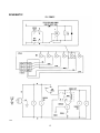
1
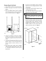
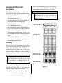
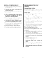
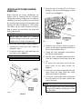
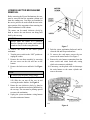
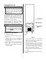
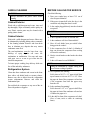
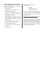
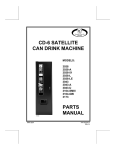
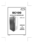
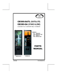
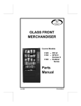
SATELLITE CD-6 CAN DRINK VENDOR EC Series SERVICE MANUAL July, 97 P/N 4208425 TABLE OF CONTENTS INTRODUCTION___________________________________________1 SPECIFICATIONS__________________________________________2 UNPACKING ______________________________________________2 INSTALLATION____________________________________________3 Grounding & Electrical Connecting to the Host LOADING INSTRUCTIONS__________________________________5 Live Display Columns INSTALLATION CHECKLIST________________________________6 PROGRAMMING THE HOST VENDOR _______________________6 Canned Drink Option Price Setting Instructions UPPER EJECTOR MECHANISM REMOVAL ___________________7 LOWER EJECTOR MECHANISM REMOVAL __________________8 REFRIGERATION UNIT ____________________________________9 Refrigeration unit removal CARE & CLEANING _______________________________________10 Cabinet Exterior Cabinet Interior Refrigeration System BEFORE CALLING FOR SERVICE__________________________10 PARTS ORDERING PROCEDURE___________________________11 SCHEMATIC ______________________________________________12 Record the Model Number and Serial Number of your vendor below. These numbers are needed to obtain quick service and parts information for your vendor. The numbers are given on the identification plate on the back side of the cabinet of the vendor. MODEL NUMBER: __________________________________________________ SERIAL NUMBER: __________________________________________________ i Each vendor is identified by a model number and a serial number which appear on the Serial Number Plate attached to the inside and rear of the vendor. Record these numbers for your records. All inquires and correspondence pertaining to this vendor should reference the model and serial numbers. INTRODUCTION This service manual contains installation and service information for the Satellite CD-6 Can Drink Vendor EC Series. This vendor operates on the “first-in, first-out” vending principle on all selections. This Satellite Vendor uses the electronics and control systems of the host vendor for all vend functions, credit accumulation, and pricing. The host vendor treats the Satellite Vendor as an added shelf or tray, utilizing the same features that apply to the host vendor, such as discount pricing, force vend, and so on. Read this manual thoroughly to familiarize yourself with the features and functions of all components. The initial set-up of a vending machine is a very important step of insuring that the equipment operates in a trouble-free manner. By following the instructions at the initial installation of the vendor, service problems can be avoided and set-up time can be minimized. The Satellite Vendor is a six (6) select refrigerated vending machine designed to vend standard 330 ml cans. Cans are stored in serpentine-type storage areas. Should you have any questions pertaining to the information in the manual, replacement parts or the operation of the vendor you should contact your local distributor, or: Each selection has a 24 volt motor-driven vend mechanism that consists of a “dual” cam arrangement. The front cam holds the product to vended at the vend position, releasing it to the delivery area during the vend cycle. The rear cam advances into the path of the cans during the vend cycle, holding them back until the vend cycle is complete. At the end of the vend cycle, the next can is released to the vend position. VendNet 165 North 10th Street Waukee, Iowa 50263-0488 USA PHONE: USA PARTS FAX: SALES FAX: If electrical malfunctions are detected by the host controller, that selection is placed out of order. The controller records that selection in memory and displays it to service personnel when the host vendor is placed in the Service Mode. Money is inserted at the host vendor and selections are made through the host vendor’s keypad. Any refund required due to over-credit is refunded at the host vendor. 1 1-515-274-3641 1-800-833-4411 1-515-987-4447 1-515-274-0390 Note the model and serial numbers of the vendor for your records. These numbers are on the Serial Plate on the back of the cabinet and/or inside the vendor. Refer to these numbers on all correspondence and inquiries about this vendor. SPECIFICATIONS GENERAL Height: Width: Depth: Weight: 68 Inches 21 Inches 30 1/8 Inches 360 Pounds 173 cm 53 cm 77 cm 163.3 kg Remove the two retaining blocks from the shipping pallet. See Figure 1A. Slide the vendor forward on the pallet until the side legs are clear of the pallet. See Figure 1B. Tilt the machine sideways until the remaining legs are clear of the pallet and remove the pallet. See Figure 1C. ELECTRICAL Power: Starting Amps: Running Amps: 230 VAC 50 Cycle 3.5 1.7 115 VAC 60 Cycle 7 3.5 CAPACITY Six Selections of 330 ml Cans Selections 1, 3 and 5 Selections 2, 4 and 6 Total Cans in Pre-Cool Area: 33 Cans each 35 Cans each 204 6 PRICING 1A Six Prices based on host vendor REFRIGERATION Unit Size: Refrigerant: Charge: 1/4 HP Hermetically Sealed R-134a 3.5 Oz. UNPACKING This vendor was thoroughly inspected before leaving the factory and the delivering carrier has accepted it as their responsibility. Any damage or irregularities should be noted at the time of delivery and reported to the carrier. Request a written inspection report from the claims inspector to file any claim for damage. File the claim with the carrier (not the manufacturer) within 15 days after receipt of the vendor. 1B Carefully remove the outside packing material in a manner not to damage the finish or exterior of the vendor. Inspect the vendor for concealed shipping damage. Report any damage hidden by the shipping material directly to the delivering carrier on a hidden damage report. 1C Figure 1 2 INSTALLATION Grounding & Electrical To minimize installation time and to avoid service problems due to improper installation, follow the instructions outlined in this manual. For proper operation of any equipment using electronically controlled components, we recommend that the electrical power supply for this vendor be on a properly polarized and grounded; isolated and/or dedicated noise-free circuit. Consult local, state and federal codes and regulations before installation of the vendor. To correct negative voltage, amperage, polarity, or ground checks, consult a licensed electrician. Position the vendor in its place of operation no further than 6 feet (1.8 m) from the power outlet or receptacle and check that the door will open fully without interference. Leave at least six inches (15 cm) of space between the back of the vendor and any wall or obstruction for proper air circulation. A noise suppresser has been installed in this vendor to compensate for any mains signal noise that could interfere with the normal operation of the controller. WARNING: Do not operate the vendor on an extension cord. CAUTION: Do not block the ventilating screens in front or in back of the vendor. Always allow free ventilation behind a bank installation, so that exhaust air is not trapped. Failure to do so could result in a refrigeration failure. The power source must be 230 VAC (±10%) 50 cycle or 115 VAC (±10%) 60 cycle. 1. Voltage Check: When the AC volt-meter probes are connected to the hot and neutral terminals, the voltmeter should indicate 230 VAC: 216-264 115 VAC: 108-132 2. Polarity and Ground Check: When the AC voltmeter probes are connected to the hot and ground terminals. the voltmeter should indicate 230 VAC: 216-264 115 VAC: 108-132 3. Amperage Check: At the fuse box or circuit breaker panel, locate the proper circuit, and ensure that the fuse or breaker protecting that circuit is rated at 13 amps or greater. Level the vendor, making sure all levelers are touching the floor. The vendor must be level for proper operation. If the vendor is properly leveled, it should not “rock” or teeter” on any of the Levelers. When the vendor is level, the door can be opened to any position and not move by itself. Try the door half closed, straight out and in a wide open position before deciding that the vendor is level. Remove all shipping brackets, tape and inner packing material from the vendor. To try to operate the vendor without removing the tape and packing material could result in damage. 3 7. Set prices for the Satellite Vendor selections. Refer to the “Price Setting Instructions” section of this manual. 8. Load product into the Satellite Vendor. See the “Loading Instructions” section. 9. Test vend both vendors for proper operation. Refer to the “Test Vend” section. Connecting to the Host 1. Unplug the host machine from its power source. 2. Remove one plug on the back of the host cabinet. 3. Insert the umbilical harness from the Satellite Vendor through the hole in the back of the host. Secure with the flat bracket. See Figure 2. NOTE: The Satellite Vendor must have at least two cans in a selection before a test vend can be performed. 10. Attach the Satellite Vendor to the host vendor. Remove the upper bracket on the host vendor, saving the three screws. Hook the Tie Plate furnished with the satellite over the lip of the Satellite Vendor. Use the saved screws to attach it to the host vendor. See Figure 3. Figure 2 4. Connect the umbilical cord from the Satellite Vendor to the connector of the host vendor. This cable is lying loose on the floor of the host vendor. 5. Verify that all harnessing and cables have been properly routed to clear all moving parts and will not interfere with the delivery of the product. 6. Plug both the host vendor and the Satellite Vendor into their electrical power source. Refer to “Grounding & Electrical” section for power requirements. Figure 3 4 Make sure that the product being loaded is placed in the proper opening and that it agrees with the product that is being displayed in the live display. LOADING INSTRUCTIONS Live Display The live display provides a full view of the products being dispensed along with the selection number and vend price for each item. 1. Open the outer door and separate the inner door from the outer door. 2. Place the product in the display window and secure in place with the retaining spring. 3. Make sure that the identification label is in plain view of the buying customer. 4. Make sure that the product being displayed is at the correct position and agrees with the product loaded in the serpentine columns. 5. Adjust the price scroll to agree with the vend price programmed into the controller of the host vendor. To verify the vend price, press the selection letter and number at the host vendor. The vend price is displayed momentarily. CAUTION: Do not store product inside the cabinet area. This restricts the air flow and causes the refrigeration unit to malfunction or possibly damage the unit. G1 G3 G5 G2 G4 G6 G2 G4 G6 G1 G3 G5 Columns There are six (6) 330 ml selections in the vendor. Cans are stored in serpentine-type columns for easy loading and dispensing. The selections are numbered from top to bottom, left to right when facing the vendor. Selections 1, 3 and 5 hold 33 cans each. Selections 2, 4 and 6 hold 35 cans each. CAUTION: When loading the columns, do not let the first cans strike the motor cams with full force. Do not load dented or damaged cans in the serpentine columns, because jams could occur. When loading the columns, place the cans into the proper opening. (See Figure 4.) Lay the cans on their side and allow them to roll down the serpentine column to the ejector mechanism. Figure 4 Keep placing cans into the column until the compartment is full to the top opening. 5 INSTALLATION CHECKLIST PROGRAMMING THE HOST VENDOR 1. All shipping brackets, packing material and tape have been removed. 2. Vendor has been properly leveled from left to right and front to back. 3. Vendor is positioned no more than 6 feet from the power outlet. 4. There is at least six (6) inches of space between the back of the vendor and any wall or obstruction for proper air circulation. 5. Vendor is plugged directly into a dedicated circuit properly polarized and grounded. 6. Vendor has been properly loaded and all items in each selection correspond to the live display. 7. The correct vend price has been programmed into the controller of the Host Vendor. 8. Each price scroll agrees with its vend price. 9. The vendor door is closed tightly and locked. Canned Drink Option The Canned Drink Option in the host vendor controller must be on for the host to recognize the Satellite Vendor. 1. After placing the host vendor in the Service Mode, press <E>. Optn displays. 2. Press <D> to access the Canned Drink Option. The current option status displays; CAnn = off or CAnY = on. 3. Press <D> to toggle the Canned Drink Option between the two options. 4. When the desired status is set, exit by pressing a function key or by exiting the Service Mode. Price Setting Instructions Price setting is done through the host vendor. To set a vend price: 1. After placing the host vendor in the Service Mode, press key <4>. Prc displays. 2. Press the selection letter and number of the item to be priced. The current price of that selection displays. 3. To increase the price, press <#>. To decrease the price, press <*>. Pressing and holding the key accelerates the change. 4. To save the new price, press a different function key, exit the Service Mode or press the selection letter and number of the next item to be priced. 6 3. Insert the Upper Can Stop (P/N 1211018) by hooking it over the rod and clamping it down over the can. See Figure 6. UPPER EJECTOR MECHANISM REMOVAL Before removing the Ejector Mechanisms, the product must be removed from the serpentine column and from the vending area. Can Stops are furnished in the service packet to be used to hold the cans in the upper portion of the serpentine when removing the ejector mechanism in a full column. The motors can be rotated clockwise slowly by hand to remove the cans that are not being held back by the can stop. CAUTION: Always rotate the motor in a clockwise direction. Damage to the motor could result if rotated too fast, or in the wrong direction. Figure 6 To remove the motor or upper ejector mechanism: 1. Turn the power switch to the “OFF” position or unplug the vendor. 2. Loosen the latch screw so the latch drops and out of the way. See Figure 5. 4. Rotate the cam clockwise slowly by hand to remove all cans that are not being held back by the Can Stop installed in Step 3. 5. Unplug the ejector mechanism wiring harness from the main motor harness. 6. Push the ejector mechanism backward until it clears the retaining rod and drops down and out. 7. To remove the vend motor, remove the two motor screws on the motor bracket. See Figure 5. 8. Remove the wire harness connections from the motor switch and circuit board tabs, noting which wire connects to which tab. 9. If necessary, cut the plastic cable tie that straps the main harness to the motor cylinder and remove the motor. NOTE: To remove only the motor, skip to Step 7. NOTE: After the motor screws have been removed, pressure will be needed to pull the motor off the cam drive shaft. Figure 5 7 LOWER EJECTOR MECHANISM REMOVAL Before removing the Ejector Mechanisms, the cans must be removed from the serpentine column and from the vending area. Can Stops are furnished in the service packet to be used to hold the cans in the upper portion of the serpentine when removing the ejector mechanism in a full column. The motors can be rotated clockwise slowly by hand to remove the cans that are not being held back by the can stop. CAUTION: Always rotate the motor in a clockwise direction. Damage to the motor could result if rotated too fast, or in the wrong direction. Figure 7 To remove the motor or the lower ejector mechanism: 1. Turn the power switch to the “OFF” position or unplug the vendor. 2. Remove the can chute assembly by removing the two screws on the side and one on the bottom. 3. Remove the latch screw and latch. See Figure 7. 7. Push the ejector mechanism backward until it clears the rod and lift upward and out. 8. To remove the vend motor, remove the two screws on the motor bracket. See Figure 7. 9. Remove the wire harness connections from the motor switch and circuit board tabs, noting which wire connects to which tab. 10. If necessary, cut the plastic cable tie that straps the main harness to the motor cylinder and remove the motor. NOTE: To remove only the motor, skip to Step 8. 4. Insert the Lower Can Stop (P/N 1200137102) Slide the can stop all the way in and screwing down the fastener. See Figure 8. 5. Rotate the cam clockwise slowly by hand to remove the cans that are not being held back by the can stop. The cam must be pointing upward to remove the mechanism. 6. Unplug the ejector mechanism wiring harness from the main motor harness. Figure 8 8 REFRIGERATION UNIT CAUTION: Do not place any object in the evaporator assembly area or inside the cabinet area that will block the air flow. This may damage the refrigeration system, which may void the refrigeration warranty. The refrigeration unit is a hermetically sealed completely self-contained modular 1/4 H.P. unit charged with 3.5 ounces of ozone-friendly R-134-a refrigerant. The complete refrigeration unit can be removed if there is a service problem. The normal setting for the refrigeration is between marked NORMAL on the control. Slight adjustment may be necessary at higher altitudes. CAUTION: Do not set the refrigeration thermostat at or above 3. This could cause the cans to freeze. A higher setting does not accelerate can cooling, it only maintains the inside of the cabinet at a colder temperature. Refrigeration unit removal 1. Unplug the power cord. 2. Remove the two (2) screws holding the suction line cover. 3. Remove only the ten (10) screws holding the refrigeration unit to the cabinet: See Figure 9 for screw location. 4. From the front of the vendor, unplug the power harness from the power switch plate. Disconnect the green ground wire from the power switch plate. Figure 9 5. From the front, unscrew the “P” clamp that holds the main motor harness and the power harness to the power switch plate. 6. From the back, pull the unit out a few inches. Remove the mastic from where the main motor cord enters the cabinet. Slide the cord out of the two slots (one on the outside of the panel and the other on the inside of the panel). 7. Use the handle on the unit and pull straight back to remove. To re-install the refrigeration unit, reverse the above procedures. 9 CARE & CLEANING BEFORE CALLING FOR SERVICE WARNING: Always disconnect the power source before cleaning. Check the following: 1. Does your vendor have at least 6”/15 cm of clear air space behind it? 2. If the power is turned off at the fuse box, is the vendor the only thing that doesn’t work? 3. Is the vendor plugged directly into the electrical receptacle? Cabinet Exterior Wash with a mild detergent and water, rinse and dry thoroughly. Wipe occasionally with a quality car wax. Plastic exterior parts may be cleaned with a quality plastic cleaner. WARNING: Do not use extension cords. Cabinet Interior 4. Is the evaporator coil free of dust and dirt? 5. Is the condenser coil free of dust and dirt? 6. Have all soft drinks been pre-cooled before being put in the vendor? 7. Is the compressor free of dust? (A blanket of dust can prevent the compressor from cooling off between workouts). 8. Has the circuit breaker at the breaker box been reset? 9. Is the cold control set on NORMAL? Wash with a mild detergent and water. Odors may be eliminated by including baking soda or ammonia in the cleaning solution. Remove and clean drain hose to eliminate any deposits that may restrict condensate water flow. The vend mechanisms must be kept clean. Any build-up of syrup deposits can cause the mechanisms to malfunction. Use soap and water with great care so as not to get water into the electrical components. To insure proper vending, keep delivery slide area free of dirt and sticky substances. NOTE: Setting the thermostat at a higher setting does not accelerate cooling of product Refrigeration System 10. Are evaporator fans running? Fold a sheet of 8 1/2” x 11” paper in half from top to bottom so it is now 8 1/2” x5 1/2”. Place the paper in front of the evaporator coil and see if the evaporator fans blow the paper away from the coil. 11. Is the condenser fan running? Fold a sheet of 8 1/2” x 11” paper in half. Place the paper in front of the condenser coils and see if it draws the paper to it 12. Is the shelf in front of the evaporator coil clear? (Free of cans, tools or other air restricting items). Clean dust from condenser and screen in the front door with a soft bristle brush or vacuum cleaner. Remove any dirt or debris from the refrigeration system compartment. Remove and clean the condensation pan. Do not block the evaporator or any area of the air flow with product or supplies. 10 9. Purchase order number, if used. 10. Mail your order to PARTS ORDERING PROCEDURE When ordering parts from your local distributor or VendNet, include the following: 1. Shipping address 2. Address where the invoice should be sent. 3. The number of parts required. 4. Always refer to the pertinent parts and/or part manual for the correct part number and description of a specific part When “RIGHT” or “LEFT” is used in connection with the name of a part, it is taken to mean that the person is facing the machine with the door closed. 5. The model number and serial numbers of the machine for which the parts are needed. 6. Any special shipping instructions. 7. Carrier desired: air or air special, truck, parcel post or rail. 8. Signature and date. VendNet 165 North 10th Street Waukee, Iowa 50263-0488 All orders are carefully packed and inspected prior to shipment. Damage incurred during shipment should be reported at once and a claim filed with the terminating carrier. If you do not have the right parts manual: contact VendNet. They will be able to assist you. Use the most accurate description you can (and the model number and serial number of the machine); include the name of the assembly in which the part is used and, if practical, a sample part. Furnish any information which will enable our Parts Department to pinpoint the exact part needed. 11 SCHEMATIC 12