1
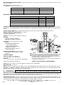
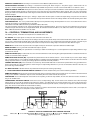
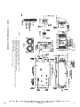
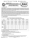
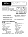
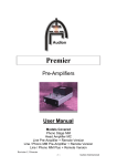
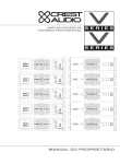
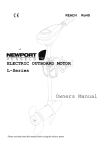
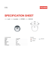
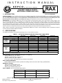
INSTRUCTION MANUAL
KEPCO
An ISO 9001 Company.
RAX
1500 WATT SINGLE OUTPUT
SWITCHING POWER SUPPLIES
CAUTION: UNIT IS SET
TO 115V AC OPERATION
I — INTRODUCTION
SCOPE OF MANUAL. This instruction manual covers the installation and operation of the Kepco RAX 1500W Series of Switching Power Supplies.
For service information, please refer to the Service Manual for the RAX 1500W Series, which can be purchased either from your Kepco Representative, or by writing directly to: Kepco Inc. 131-38 Sanford Avenue, Flushing, New York 11352, U.S.A. When ordering a Service Manual, please state
Model Designation and Serial Number of your RAX power supply. This information can be found on the nameplate of the unit.
DESCRIPTION. The Kepco RAX 1500W Series consists of four models of switching power supplies, with a single output as shown in Table 1. Units
may be operated with either 120V a-c or 220-240V a-c, 47-440Hz input. They will also operate on 240V to 370V d-c input. The RAX 1500W Series
employs a light weight ferrite core with 165 KHz switching frequency. Regulation is provided by pulse width modulation. A FET power stage, operating
in the forward conversion mode provides a smooth isolated d-c output. A thyristor “soft-start” circuit prevents excessive turn-on current surge. Overvoltage protection and optically isolated remote TTL on-off control is provided. Current limiting with automatic recovery from short circuit is featured.
Units are enclosed in a wrap-around aluminum case with an LED “output present” light visible on the terminal side of the case.
Table 1 contains specifications and operating limits of individual RAX 1500W Series models. Section II (following) contains specifications and operating limits common to all RAX 1500W Series Models.
II — SPECIFICATIONS
The following specifications are at nominal input voltages at 25°C unless otherwise specified.
TABLE 1. OUTPUT RATINGS AND SPECIFICATIONS, RAX 1500W SERIES
RAX 5-300K
RAX 12-125K
5V
12V
ADJUSTMENT RANGE
4.0 - 5.5V
8.4 - 13.2V
MAXIMUM
50° C amb.
300.0A/1500W
125.0A/1500W
OUTPUT
60° C amb.
210.0A/1050W
87.5A/1050W
RATINGS
71° C amb.
120.0A/600W
50.0A/600W
(AMPS, WATTS)
EFFICIENCY
79%
81%
CURRENT LIMIT (AMPS)
315.0 - 350.0
130.0 - 140.0
OVP RANGE (VOLTS)
6.0 - 6.9
13.7 - 15.7
source (typ)
5
15
RIPPLE
source (max)
20
30
AND
switching (typ)
50
60
NOISE(1)
(mV p-p)
switching (max)
120
150
spike noise (max)(2)
200
250
(1) Source component 2x source frequency, and switching component approximately 165KHz.
(2) Measured with a 50 MHz bandwidth, p-p.
MODEL
OUTPUT VOLTS, d-c
RAX 24-65K
24V
16.8 - 26.4V
65.0A/1560W
45.5A/1092W
26.0A/624W
83%
68.0 - 72.0
27.0 - 30.5
25
40
60
150
300
RAX 48-30K
48V
32.6 - 52.8V
30.0A/1440W
21.0A/1008W
12.0A/576W
84%
32.0 - 35.0
55.0 - 59.0
35
90
70
150
500
INPUT VOLTAGE: (Jumper selectable from front panel, see Section III):
120V a-c nominal, range: 85 -132V a-c
220-240V a-c nominal, range: 170 -264V a-c,
320V d-c nominal, range: 240 -370V d-c
For d-c input, remove shorting link from left side barrier strip terminals.
INPUT SOURCE FREQUENCY:
Nominal 50/60 Hz; Range 47-440 Hz. (At 440 Hz the leakage current exceeds the VDE safety specification limit.)
BROWNOUT VOLTAGE:
120V a-c input selection, 80V a-c min.
220-240V a-c input selection, 160V a-c min.
320V d-c input selection, 220V d-c min.
INPUT CURRENT: (At 25°C with nominal output power):
NOMINAL INPUT VOLTAGE
MINIMUM INPUT VOLTAGE
120 V a-c input selection
INPUT SOURCE
25A - 32A
21A -41A max.
220-240V a-c input selection
16A - 18A
18A -36A
7.0A max. (320V input)
9.0A max. (240V input)
d-c input selection
KEPCO, INC. !"! 131-38 SANFORD AVENUE !" FLUSHING, NY. 11352 U.S.A.!" TEL (718) 461-7000!"! FAX (718) 767-1102!!
http://www.kepcopower.com "! email: [email protected]
©2000, KEPCO, INC
Data subject to change without notice
228-1229 REV 2
1
INPUT PROTECTION AND SOFT START: A thyristor soft start circuit reduces start-up surge. Units are protected against shorts by an input
fuse. Fuse value 50A.
INPUT SURGE: At 25°C from cold start:
NOTE: There are two input surges at turn-on:
FIRST SURGE (1/2 of first input cycle)
SECOND SURGE (3ms max.)
120 V a-c input selection
INPUT SOURCE
20A max.
130A typ.
220-240V a-c input selection
40A max.
160A typ.
320V d-c input selection
40A max.
160A typ.
STABILIZATION:
CHARACTERISTIC
TYPICAL
MAXIMUM
0.2%
1.0%
Load Effect, measured at sensing terminals (10% - 100% load change)
0.3%
1.0%
Temperature effect (0 to 71°C)
0.2%
1.2%
Combined effect (envelope)
0.7%
3.0%
Drift (8 hr. at 25°C after half-hour warm-up)
0.2%
0.5%
Source Effect (min - max)
TRANSIENT RECOVERY: A step load change from 50% to 100% of rated load current, produces no more than 4% output voltage excursion, .
Recovery to 1% of the original voltage is less than 1 millisecond. The step load change should be greater than 200ms; Tr, Tf should be greater
than 3ms.
OUTPUT HOLDING TIME: Output is maintained for 20 milliseconds minimum upon input interruption (30 milliseconds typical).
AMBIENT OPERATING TEMPERATURES: See Table 1.
STORAGE TEMPERATURE: -20°C to + 75°C.
LINKS
(SEE NOTE)
HUMIDITY: 20% to 95% relative humidity, noncondensing
ALTITUDE:
Operating: 10,000 feet (3048.0m)
Nonoperating: 35,000 feet (10,668m)
ISOLATION: (at 20°C ambient, 85% relative
humidity):
Between input and output terminals,
3.75 KV a-c for 1 minute
(with Y-capacitors removed).
Between input and output or chassis,
2000V a-c for 1 minute.
Between output terminals and chassis,
500V a-c for 1 minute.
INSULATION RESISTANCE: Between output
and chassis, 100 megohms minimum
(500V d-c).
LEAKAGE CURRENT:
1.0mA max at 120V a-c (U.L. Method)
2.0mA max at 240V d-c (U.L./VDE Method)
VIBRATION: Three Axes: 1 hour each axis, nonoperating
5-10Hz., 10 mm amplitude , 10-55Hz., 2g
NOTE:
THE SENSE LEADS MUST NEVER BE DISCONNECTED FROM THE OUTPUT. IF THE
SENSE LEADS ARE ALLOWED TO FLOAT FREE OF THE OUTPUT, THE OUTPUT VOLTAGE WILL RISE TO THE OVERVOLTAGE POINT AND THE UNIT WILL SHUT DOWN.
• FOR REMOTE SENSING CONNECT THE SENSE TERMINALS TO THE LOAD AS
SHOWN, AND REMOVE THE TWO SENSING LINKS.
•
FOR LOCAL SENSING LEAVE THE SENSING LINKS IN PLACE AND CONNECT THE
LOAD DIRECTLY TO THE BUS BAR.
FIGURE 1. LOAD CONNECTION - REMOTE SENSING
SHOCK: Three axes, 20g, 11+/- 5 ms pulse duration, 3 shocks each axis, nonoperating
EMI CONDUCTED: FCC Class A
SAFETY: All units designed to meet UL 1950D3, UL 478, CSA Electrical Bulletin 1402C (RAX 48-30K Level 1, other RAX models Level 5),
VDE 0806, TÜV Rheinland EN60950 and IEC 950 Safety Standards. RAX are CE marked per the Low Voltage Directive (LVD),
EN60950. [The standards do not apply with DC input operation].
III — OPERATION
UNIT WILL NOT WORK WITH SENSE LEADS DISCONNECTED (SEE FIG. 1).
INSTALLING THE POWER SUPPLY: Refer to Figure 3. The unit may be mounted on one of the three mounting surfaces. Mounting holes
are provided for each mounting configuration. The air surrounding the power supply must not exceed the ambient values given in Table 1.
Allow at least 1.0” free space at the rear of the unit to insure free air movement from the fans.
CONNECTING THE LOAD: The load is connected as shown in Figure 1. Error sensing may be done at the load terminals when it is necessary to compensate for voltage loss in the connecting wires. The jumper links must then be removed from the sense terminals. The unit
will compensate for up to 0.4 volts loss per connecting wire. In the RAX 5-300K it is 0.25 volts.
092200
KEPCO, INC. !"! 131-38 SANFORD AVENUE !" FLUSHING, NY. 11352 U.S.A.!" TEL (718) 461-7000!"! FAX (718) 767-1102!!
http://www.kepcopower.com "! email: [email protected]
228-1229 REV 2
2
PARALLEL CONNECTION: Refer to Figure 2. Connect the Current Balance (CB) terminals as shown.
SELECTING INPUT VOLTAGE: Input voltage is selected with a shorting link. Refer to Figure 1. The power supply is delivered for 115V a-c
operation. Remove shorting link from left side barrier strip terminals to operate the unit from a nominal 220-240V a-c or 320V d-c source.
REMOTE TURN-ON TURN-OFF When power is on at the source the unit may be turned on or off with the remote control feature. The output of the
remote turn-on/off terminals operates at TTL logic levels (2.4V “high” from the unit and 0.0 to 0.4V short to ground, “low”). The unit is turned off by
bringing the remote turn-on/off terminals to “low” logic level with a switch or solid state device. If the remote on/off feature is not desired, the terminals
should be left open.
VOLTAGE ADJUSTMENT: Refer to Figure 3. Voltage is adjusted from the front panel as marked. To adjust voltage, first place the unit under an
operating load, then monitor the + and - sense terminals with a precision voltmeter and turn the voltage control to the desired operating value. Refer
to Table 1 for Adjustment Range.
FUSE PROTECTION: The user is provided with a 50A input fuse for protection during normal operation. The fuse is accessible after the cover is
removed; refer to Figure 3. The following fuse is specified.
KEPCO P/N: 541-0105 or Manufacturer Fuji P/N CR2LS-50/UL, 50A, 250V ;
The Unit also employs internal fuses for safety and protection against catastrophic failures. These fuses are only accessible when the unit is disassembled for repair. Two soft start fuses Kepco P/N 541-0104, or manufacturer Uchihashi P/N 121, 2A, 250V; and a switcher fuse Kepco P/N 5410048 or Manufacturer Bussman ABC 15A, 15A, 250V.
IV — CONTROLS, TERMINATIONS, AND ADJUSTMENTS
The following controls, terminations and adjustments are available to the user.
D-C OUTPUT. The output appears on heavy bus bars at the front center of the unit.
+ SENSE, – SENSE. These leads compensate for voltage error and must be placed directly on the load terminals for the most accurate error tracking. The unit is delivered with removable links on the front panel that connect the sense leads directly to the output bus terminals. The links may be
removed and the sense leads connected directly to the load. This compensates for voltage drop in the leads to the load. Refer to Figure 1
MONITOR. The monitor leads are placed across the output and may be connected to a precision voltmeter to monitor output.
MONITOR LIGHT. This a a green LED that is ON when output is present.
VOLTAGE ADJUST (R156). This potentiometer is mounted just below the monitor light. It is used to adjusted the output voltage within the range
specified in this manual.
REMOTE CONTROL (RC). The RC leads cause the unit to turn off when the leads are brought to ground potential with a mechanical switch or TTL
control. Use of remote control is optional.
REMOTE VOLTAGE ADJUST (RV). A potentiometer placed between the RV terminal and the + Sense terminal may be used to adjust voltage
from a remote location. Its use is optional. For RAX 48-30K use a 10K ohm external potentiometer. All other models use 5K ohm. When the external
voltage adjustment feature is used the panel voltage adjustment should be turned fully clockwise.
CURRENT BALANCE (CB). These terminals are used when up to three RAX 1500 units are connected in parallel. When using a parallel connection the CB terminals are connected together as shown in Figure 2. Output voltage tolerance 5% per unit, current balance tolerance 10% max., output current range nominal 20-90%.
A-C INPUT VOLTAGE. Labelled terminals are provided on the front panel for selecting input voltage.
V - SHUT-DOWN PROTECTION AND REMOTE CONTROL Turn-off or shutdown takes place under the following conditions:
REMOTE CONTROL: Bringing the RC terminals together with either a mechanical switch or logic control causes the unit to turn off and remain off
as long as the condition is maintained. Output resumes immediately when the remote terminals are reopened.
FAN FAILURE: The Unit will not operate unless both fans are operating. If either fan stops rotation, the unit shuts down and remains shut down as
long as the condition exists.
OVERCURRENT AND SHORT CIRCUIT: Overcurrent causes an abrupt voltage drop. Current remains at the maximum value. When the output
voltage falls to less than 70% of nominal for 20 seconds, the output is shut down but the fans remain operating. If the cause of the overcurrent is
removed within 20 seconds, output returns to normal. If overcurrent remains beyond 20 seconds, a restart cycle is required as described in the foregoing. The unit must remain off for 30 seconds before restarting.
OVERTEMPERATURE: A thermistor heat sensor is located in the switcher heatsink. When heatsink temperature reaches 120° C, the output cuts
off and remains off as long as the temperature remains above 120° C.
FIGURE 2. PARALLEL CONNECTION USING CURRENT BALANCE
092200
KEPCO, INC. !"! 131-38 SANFORD AVENUE !" FLUSHING, NY. 11352 U.S.A.!" TEL (718) 461-7000!"! FAX (718) 767-1102!!
http://www.kepcopower.com "! email: [email protected]
228-1229 REV 2
3
NOTES:
1.
2.
3.
4.
Dimensions in parentheses are in millimeters, others are in inches.
TOLERANCES: ±0.04” (±1.0 mm) except as noted.
MOUNTING SCREW PENETRATION: 0.024” (6 mm) maximum.
MATERIAL AND FINISH: A) Frame is aluminum, phosphate coated; B) CHASSIS, Steel, Cadmium
Plated, Chromate Wash.
WEIGHT: 17.6 lbs (8.0 Kg.) max., 16.53 lbs (7.5 Kg) typ.
228-1229 REV 2
092200
5.
FIGURE 3. OUTLINE DRAWING, RAX 1500W SERIES
4
KEPCO, INC. !"! 131-38 SANFORD AVENUE !" FLUSHING, NY. 11352 U.S.A.!" TEL (718) 461-7000!"! FAX (718) 767-1102!!
http://www.kepcopower.com "! email: [email protected]