1
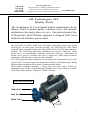
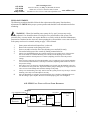
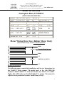
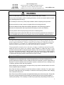
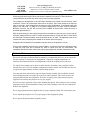
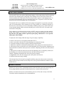
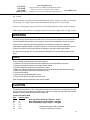
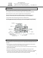
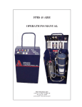
ASL-83930
ASL-83940
ASL-83980
Pump & Motor
ASL Technologies, LLC
10525 W. US Hwy 30, Bldg. 3D, Wanatah, IN 46390
Phone 219.733.2777 or Toll Free 888-333.2990
Facsimile 219.733.2779 or e-mail [email protected] www.aslfilter.com
ASL Technologies, LLC
Quality Policy
ASL Technologies, LLC was founded with the commitment to be the
industry leader in product quality, customer service and customer
satisfaction in the market places we serve. Our patented product line
of Electrostatic Fluid Filtration equipment is designed, built, tested
and delivered with these goals in mind.
The ASL-83940 (40 GPH) Tuthill Pump and Motor combination replaces the Viking
SG0518-GOV (40 GPH) pump and motor assembly. The ASL-83980 (80 GPH) Tuthill
Pump and Motor combination replaces the Viking SG0535-GOV (80 GPH) pump and motor
assembly. The Tuthill Pump and motor combination was chosen to replace the Viking
product due to its maintainability, reliability, performance, and cost. Additionally, all
needed service parts are available from ASL to support the Tuthill Pump and Motor
combination without having to replace the entire assembly.
The Tuthill pump and motor combination was production line incorporated by ASL in the
spring of 2001. Your spare/replacement Pump/motor will have a grey Baldor motor. Wiring
and part number information for the motor is contained in this manual.
When initially installing (replacing) a Viking pump and motor with a Tuthill, the
maintenance man will have to drill additional mounting holes, as the Tuthill is a NEMA
48YZ Frame motor, while the Viking was a NEMA 56 Frame.
Baldor Motor/Tuthill Pump
Outlet Port
Inlet Port
Relief Valve
2.750”
1
ASL-83930
ASL-83940
ASL-83980
Pump & Motor
ASL Technologies, LLC
10525 W. US Hwy 30, Bldg. 3D, Wanatah, IN 46390
Phone 219.733.2777 or Toll Free 888-333.2990
Facsimile 219.733.2779 or e-mail [email protected] www.aslfilter.com
ASL-83930 / 40 / 80 Spare / Replacement Parts
DESCRIPTION
PART NUMBER
Call ASL for any parts not listed
80 GPH Pump/Motor/coupler ASSY
80 GPH Pump only
40 GPH Pump/Motor/coupler ASSY
40 GPH Pump only
30 GPH Pump/Motor/coupler ASSY
30 GPH Pump only
Motor only – 60 Hz (with 3 piece coupler)
Motor only – 50/60 Hz (with coupler)
Three piece pump to motor coupler only
Pump Replacement Parts
‘O’ ring (viton)
Seal Assembly (viton)
Other parts not listed
ASL-83980-7
0-LEV-040-CC-A-7
ASL-83940-7
00-LEV-040-A-7 (Viton Seals)
ASL-83930
30-LEV-CC-A-9821
88514 (30, 40 & 80) 60Hz Only
88471 (30, 40 & 80) 50/60Hz 1425/1725
1L519 (30, 40 & 80)
P 701-34-77
1LA9-7
Call ASL
Removal/Replacement Adjustment
PUMP/MOTOR ASSEMBLY
The pump and motor assembly used in your FPRS is designed for continuous duty, and will
give many years of trouble free service. For your convenience, the pump manufacturers service
manual is located in the last section of this manual, starting on page 7. The pump and motor consists
of three basic parts, which are all easily field replaceable. The pump itself is attached to the motor
housing with 3 ¼ -20 x ¾” long bolts and lock washers.
Coupling the pump to the motor is a three-piece tang coupler, which consists of two hard
plastic splines and a center metal adapter. Note that the pump shaft has the “male” tang and the
motor shaft is the female end. Replacement of the pump or coupler is straightforward, and should
present no problem for maintenance. See the following section for removal and replacement of the
pump, along with required adjustments.
2
ASL-83930
ASL-83940
ASL-83980
Pump & Motor
ASL Technologies, LLC
10525 W. US Hwy 30, Bldg. 3D, Wanatah, IN 46390
Phone 219.733.2777 or Toll Free 888-333.2990
Facsimile 219.733.2779 or e-mail [email protected] www.aslfilter.com
Pump/Motor COMBINATION
Replacement of the pump and motor is straightforward. The pump/motor is secured with studs or
bolts. For ease of access, the Electrostatic Cell should be removed.
1.
All Pump/Motor assemblies are pre-wired at the factory for the correct rotation and
voltage, with a 36” length of S.O. cord. Depending on ASL unit model, strip, prepare
and wire the bare end of the SO cord into your unit as needed. Note that wire
connections and color codes are located on the motor nameplate, as well as page 6 of
this manual.
2.
The hose connections to the motor are of the “push-lock” type, and will have to be cut.
Slit the inlet and outlet hoses the minimum amount necessary to allow removal of the
hoses from the push-lock fittings. Trim the hose ends square for re-installation.
Excessive slitting and /or trimming will render the hoses too short, and they will have to
be replaced. There should be enough excess hose length to remove and replace the pump
at least once or twice.
3.
With the wiring and hoses disconnected, remove the four ¼-20 nuts and washers, and
remove the pump/motor assembly from the cabinet.
4.
With both the old and new pumps/motors on the workbench, transfer the inlet/outlet
hose fittings to the new pump/motor. Take care to align the fittings the same way they
were. Use a suitable thread sealer on all pipe threads.
5.
Install the pump/motor into the cabinet by reversing the above instructions. A drop of
lubricant on the push-lock fittings will ease installation of the hoses.
6.
Secure all wiring and hoses and proceed to “PUMP ADJUSTMENTS” on page 5.
Replacement of PUMP only
If you have determined that only the pump needs to be replaced, the motor and it’s electrical
connections can remain attached to the cabinet.
1.
Remove the pump inlet and outlet hoses. The fittings are of the “push-lock” type, and
the hoses must be cut. Slit the inlet and outlet hoses the minimum amount necessary to
allow removal of the hoses from the push-lock fittings. Trim the hose ends square for reinstallation. Excessive slitting and /or trimming will render the hoses too short, and they
will have to be replaced. There is enough excess hose length to remove and replace the
pump at least once or twice.
2.
Remove the three ¼-20 bolts and lock-washers securing the pump to the motor.
3.
Separate the pump from the motor by pulling straight up on the pump body while
rotating the pump.
4.
There is a three-piece coupler connecting the pump to the motor. During pump/motor
separation, one or more of these coupler pieces may come out with the pump. Carefully
inspect the three-piece coupler for signs of wear or damage. The coupler should be
replaced if found defective. Note that a new coupler is included with a replacement
motor, and a pump and motor combination, but not with a replacement pump. Before
ordering a replacement pump, determine if the coupler will need to be replaced, so it can
be ordered at the same time. It is a good idea to replace the coupler when replacing
either the pump or the motor.
5.
With the old and new pumps on the workbench, transfer the inlet and outlet fittings to
the new pump. Take care to align the fittings as they were. Use a suitable thread sealer
on all pipe threads.
3
ASL-83930
ASL-83940
ASL-83980
Pump & Motor
6.
7.
8.
9.
10.
ASL Technologies, LLC
10525 W. US Hwy 30, Bldg. 3D, Wanatah, IN 46390
Phone 219.733.2777 or Toll Free 888-333.2990
Facsimile 219.733.2779 or e-mail [email protected] www.aslfilter.com
Install the plastic female tang coupler and the metal center section coupler pieces on the
motor shaft. Install the male tang coupler piece on the new pump.
Using a twisting motion, install the pump onto the motor, taking care to align the splines
of the couplers. Once aligned, the pump will “drop” into position.
Re-install the three ¼-20 bolts and lock-washers thru the pump to the motor. Note that
these bolts are ¾” long. Longer bolts will bottom out.
Re-install inlet and outlet hoses. A drop of lubricant on the push-lock fittings will ease
installation of the hoses.
Proceed to “PUMP ADJUSTMENTS” on page 5.
Replacement of MOTOR only
If you have determined that only the motor needs to be replaced, the pump and its attached hoses can
remain in the cabinet.
1.
Start by removing the motor wiring box cover and disconnecting the wire nuts tying the
SO cord to the motor leads. The green ground wire is secured with a green screw to the
motor inside the motor wiring box. Pull the SO cord out of the motor wiring box and
plastic “Heyco” connector. Note that wire connections and color codes are located on
the motor nameplate, as well as page 6 of this manual.
2.
Remove the three ¼-20 bolts and lock-washers securing the pump to the motor.
3.
Separate the pump from the motor by pulling straight up on the pump body while
rotating the pump.
4.
There is a three-piece coupler connecting the pump to the motor. During pump/motor
separation, one or more of these coupler pieces may come out with the pump. Carefully
inspect the three-piece coupler for signs of wear or damage. The coupler should be
replaced if found defective. Note that a new coupler is included with a replacement
motor, or pump and motor combination, but not with a replacement pump.
5.
With the pump and motor separated and the wiring removed, remove the four ¼-20 nuts
and flat washers securing the motor to the cabinet studs and lift the motor out of the
cabinet.
6.
Transfer the black “Heyco” wiring fitting and locknut to the wiring box of the new
motor.
7.
Install the plastic female tang coupler and the metal center section coupler pieces on the
new motor shaft. Install the male tang coupler piece on the pump.
8.
Install the new motor onto the cabinet studs and secure with four ¼-20 locknuts and flat
washers.
9.
Using a twisting motion, install the pump onto the motor, taking care to align the splines
of the couplers. Once aligned, the pump will “drop” into position.
10.
Re-install the three ¼-20 bolts and lock-washers thru the pump to the motor. Note that
these bolts are ¾” long. Longer bolts will bottom out.
11.
Re-install the SO cord through the “Heyco” fitting and re-connect wiring in accordance
with the diagram on page 41 of this manual.
12.
Tie up any loose wiring and return the unit to service. Note that pump adjustments
should not be required when replacing the motor only.
4
ASL-83930
ASL-83940
ASL-83980
Pump & Motor
ASL Technologies, LLC
10525 W. US Hwy 30, Bldg. 3D, Wanatah, IN 46390
Phone 219.733.2777 or Toll Free 888-333.2990
Facsimile 219.733.2779 or e-mail [email protected] www.aslfilter.com
PUMP ADJUSTMENTS
The following procedure should be followed after replacement of the pump. Note that these
adjustments are CRITICAL to proper system operation and should be read and understood before
continuing.
WARNING – When first installing a new pump, the “by-pass” pressure may not be
correctly adjusted. Care should be taken to avoid gross over-pressurization of the system. This
procedure may, on some models, also require that the cover safety switch be defeated. Maintenance
personnel are cautioned to take extra care when operating the system with the covers removed. Refer
to the pump vendor service manual, starting on page 7 of this manual.
1.
2.
3.
4.
5.
6.
7.
8.
9.
Start system and wait until output flow is observed.
Remove the acorn nut on the pump relief valve.
Insert a screwdriver into the slot of the adjusting screw and hold it steady.
Loosen the locking nut with a wrench by turning counterclockwise.
Slowly close the throttling ball valve until the system pressure reaches 40 psi. If the pressure
fails to reach this level with the throttling valve closed, turn the adjusting screw inward
(clockwise) until the desired pressure is reached. (Adjusting clockwise raises the pressure
setting).
If the pressure reaches 40 psi before the throttling valve is completely closed, turn the adjusting
screw outward (counterclockwise) until 40 psi is reached. (Adjusting counterclockwise lowers
the pressure setting).
Once the by-pass is set at 40 psi. with the throttling valve closed, open the throttling valve for a
few minutes to let the system flow. Operation with the pump in full bypass for long periods will
cause excessive heat buildup and could cause damage to the pump.
Slowly close the throttling valve fully. Observe that the system pressure stays at 40 psi. with the
throttling valve fully closed. Re-adjust if necessary.
Once all adjustments are complete, open the throttling valve completely and tighten the nut to
lock the setting in place. Replace the acorn nut on the pump by-pass valve and tighten.
ASL FPRS U NIT T YPICAL F LUID F LOW D IAGRAM
OUTLET
Cust supplied I/O hoses
Hydraulic/Oil
Reservoir
INLET
Grey Hose
40
GPH
Pump
40 psi max.
Sample Port
Water
Absorber
Electrostatic
Cell
Blue Hose
Drain
5
ASL-83930
ASL-83940
ASL-83980
Pump & Motor
ASL Technologies, LLC
10525 W. US Hwy 30, Bldg. 3D, Wanatah, IN 46390
Phone 219.733.2777 or Toll Free 888-333.2990
Facsimile 219.733.2779 or e-mail [email protected] www.aslfilter.com
Motor Service Data
Nameplate Data, P/N 88514
(GREY BALDOR MOTOR)
Model:
Volts:
H.P.:
RPM:
34G510-5506
115/208-230
¼
1725
FLA:
5.0/2.6-2.5
SFA:
5.6/3-2.8
NEMA Eff: 55%
P/N:
Hz:
FR:
SF:
Max
Amb.
Time
Rate:
PF:
88514
60
48 YZ
1.35
40°C
104°F
Cont.
Duty
57%
KVA Code: L
Phase:
1
ENC:
TEFC
INS:
B
Baldor Motors
Motor Wiring Data (Grey Baldor Motor Only)
(Motor is ASL Factory wired Lo Volt CW Rotation)
(2)
(4)
(5)
(8)
(3)
(1)
(1)
(3)
(2)
(8)
(5)
(4)
Do not reverse rotation!
White
Lo Volt
(Factory Wired this way)
Black
L1
Hi Volt
(208/230 Volt ONLY)
L2
The following pages contain the Installation and Service Instructions for
the Tuthill L Series pumps. The model used in the ASL-FPRS-S40
Cabinet is 00LEV-040-CC-A. S-30 and S-8 units use 30-LEV-CC-A-9821.
Eighty (80) GPH units use the 0LEV-040-CC-A pumps. The manual is
reprinted with permission from the Tuthill Pump Group.
6
ASL-83930
ASL-83940
ASL-83980
Pump & Motor
ASL Technologies, LLC
10525 W. US Hwy 30, Bldg. 3D, Wanatah, IN 46390
Phone 219.733.2777 or Toll Free 888-333.2990
Facsimile 219.733.2779 or e-mail [email protected] www.aslfilter.com
Installation and Service
Instructions
L Series Pumps
Relief Valve Inlet Port Outlet Port
The 80 GPH pump is 0-LEV-040-CC-A-7
The 40 GPH pump is 00-LEV-040-CC-A-7
The 30 GPH pump is 30LEV-CC-A-9821
7
ASL-83930
ASL-83940
ASL-83980
Pump & Motor
ASL Technologies, LLC
10525 W. US Hwy 30, Bldg. 3D, Wanatah, IN 46390
Phone 219.733.2777 or Toll Free 888-333.2990
Facsimile 219.733.2779 or e-mail [email protected]
www.aslfilter.com
General Description
Tuthill’s LA and LE Series are compact, highly efficient, cast iron positive displacement rotary
gear pumps with a mechanical seal. Built in six sizes, they provide nominal capacities from .5 to
14 gallons per minute and pressures up to 500 psi (300 psi in the 5LE). They are self priming and
particularly suited to handle liquids of 35 to 1000 SSU viscosity. Higher viscosities can be
handled at reduced speeds.
The LA Series is supplied with a two-bolt flange, the LE Series with a three-bolt flange.
Optional mounting feet are available for both Series. An internal relief valve is an option with
the LE Series. Both Series are bi-rotational (unless outfitted with a relief valve) and designed
for direct drive at standard motor speeds, with modifications available for indirect drive.
The Pumping Principle
Tuthill’s LA and LE Series employ the internal
gear pumping principle. There are only two
moving parts. Pumping action is based on a
rotor, idler gear and crescent-shaped partition
cast integral with the cover.
Power applied to the rotor is transmitted to the
idler gear with which it meshes. The space
between the outside diameter of the idler and
the inside diameter of the rotor is sealed by the
crescent.
As the pump starts, the teeth come out of
mesh, increasing the volume. This creates a
partial vacuum, drawing the liquid into the pump
through the suction port.
The liquid fills the spaces between the teeth of
the idler and the rotor and is carried past the
crescent partition through the pressure side of
the pump.
When the teeth mesh on the pressure side, the liquid is forced from the spaces and out through
the discharge port.
8
ASL-83930
ASL-83940
ASL-83980
Pump & Motor
ASL Technologies, LLC
10525 W. US Hwy 30, Bldg. 3D, Wanatah, IN 46390
Phone 219.733.2777 or Toll Free 888-333.2990
Facsimile 219.733.2779 or e-mail [email protected]
!
www.aslfilter.com
WARNING
Failure to follow these instructions could result in serious bodily injury or death.
These pumps should not be used for handling plain water, corrosive or abrasive liquids or liquids
not possessing adequate lubricity.
Do not attempt to work on any Tuthill pump installation before completing the steps below.
Disconnect the drive so that it cannot be started while work is being performed.
Review the Material Safety Data Sheet (MSDS) applicable to the liquid being pumped to
determine its characteristics and the precautions necessary to ensure safe handling.
Vent all pressure within the pump through the suction or discharge lines.
All Tuthill pumps contain residual 200 SSU lube oil from the factory production test. Determine if
this is compatible with the fluid you are pumping. If the fluid is incompatible, consult the factory.
Location
LA and LE Series pumps are designed for working pressures up to 500 psi (300 psi in the 5LE)
and are required to develop 25” mercury vacuum at 0 psi on factory test. While these pumps will
develop as high as 27” of vacuum, it is a sound engineering practice to avoid extreme vacuum
whenever possible. Select a pipe size to reduce line friction loss to a minimum.
The pump should be located as close to the source of supply as conditions permit and if possible,
below the level of the liquid in the reservoir. When necessary to locate the pump in a pit,
provisions should be made to safeguard against flooding. Care must be taken to properly support
the suction and discharge piping so that no strain is put on the pump due to either weight or
expansion. Piping strain can result in misalignment, hot bearings, worn couplings, and vibration. It
is important that the piping used be clean and free of chips or scales.
Proper Installation
Unsatisfactory pump installations are usually characterized by poor suction conditions for the
specific liquid being handled. Suction conditions should be minimized to prevent vaporization of
the liquid. If vacuum conditions force the liquid to vaporize, cavitation will occur, resulting in loss
of capacity, premature wear and noisy operation.
When handling high viscosity liquids, the speed of the pump must be reduced and the size of the
lines increased to prevent cavitation.
Note: Pipe line friction increases at a rapid rate with an increase in viscosity. For a given pump
and motor, larger pipe lines are necessary to maintain the same pump pressure when changing
from a thin fluid to a thick one.
Most Tuthill LA and LE Series pumps are supplied with both ports on the same plane. Pumps with
this type of porting arrangement should always be installed with both ports pointing upward to
insure proper priming. If it is necessary to install the pump with the ports pointing to either side, it
9
ASL-83930
ASL-83940
ASL-83980
Pump & Motor
ASL Technologies, LLC
10525 W. US Hwy 30, Bldg. 3D, Wanatah, IN 46390
Phone 219.733.2777 or Toll Free 888-333.2990
Facsimile 219.733.2779 or e-mail [email protected]
www.aslfilter.com
is recommended that the top port be the suction port. This will prevent gravity induced drainage of
fluid through the suction port. When pipe lines are installed, an inverted “U” bend should be
incorporated into the suction line close to the pump for priming purposes.
The multiple port arrangement in the 5LE offers flexibility but is limited to some common sense
restrictions. There is an inlet and an outlet side to the pump. There must always be at least one
pipe on each side. Units ordered with the side port option (modification S) are shipped with port
plugs in the top ports. To adapt to a 90° porting arrangement, the plugs must be relocated.
Because of its size, the 5LE will not mount onto a NEMA 48 frame motor unless the motor is
shimmed approximately ¼”.
With the ports facing up, and viewing the pump from the shaft end, the inlet port is on the right for
clockwise rotation and on the left for counter-clockwise rotation. Pumps with built in relief valves
are directional. Therefore rotation must be specified at time of order. The adjusting screw of the
internal relief valve must always be located on the suction side of the pump.
Pumps should be filled with oil at installation and should never be allowed to run dry.
Every pump installation should have a good foundation. Its structure should be sufficiently strong
to hold the pump rigid and to absorb any strain or shock that may be encountered. The
installation should be leveled, checked for proper piping alignment, and then fastened securely.
Method of Drive
Direct drive through a traditional flexible coupling is recommended. However, do not expect the
flexible coupling to compensate for misalignment. Contact the coupling manufacturer to
determine the maximum amount of misalignment to which the coupling can be subjected.
LA and LE Series pumps can be driven in either direction of rotation, unless outfitted with an
internal relief valve. The seal chamber communicates with the neutral zone and therefore the seal
is subjected to approximately one half of the discharge pressure.
All pump and motor units must be properly aligned during assembly and periodically checked
since misalignment may occur later due to abuse or other conditions. Pipe strain can force the
pump and motor shafts out of alignment. Therefore, all piping to the pump must be properly
supported. Do not allow the pump to act as a pipe support.
Provide for proper expansion of pipes when handling hot liquids. Allow pump to reach operating
temperature slowly. Rapid temperature change can result in damage to the cast iron components.
Recheck the alignment.
Never align a pump and motor supplied with a pin type coupling without first removing the pins.
Never depend upon sight or feel. Use proper gauges when aligning the pump.
Never operate the pump without all guards in place.
10
ASL-83930
ASL-83940
ASL-83980
Pump & Motor
ASL Technologies, LLC
10525 W. US Hwy 30, Bldg. 3D, Wanatah, IN 46390
Phone 219.733.2777 or Toll Free 888-333.2990
Facsimile 219.733.2779 or e-mail [email protected]
www.aslfilter.com
Relief Valve Protection
The LA and LE Series are positive displacement pumps. As the pump rotates, liquid is positively
delivered to the discharge side of the pump. If the discharge line is closed off, pressure will
increase until the drive stalls and/or fails, the pump breaks or ruptures, or the piping bursts. To
prevent this from happening, the use of a pressure relief valve is required. A relief valve that
directs the flow back to the supply tank is recommended.
The internal relief valve available on LE Series pumps is designed for overpressure protection
only. It is not intended as a flow control device or for any similar use. Continuous operation of
the relief valve will result in excessive heat buildup within the pump cavity, which could cause
serious internal damage. Make certain the adjusting screw of the relief valve is located on the
suction side of the pump.
Unless otherwise specified at the time of order, all LEV pumps are supplied with the standard
spring, with a range of 55-120 psi (40-70 in the 5LE), set to provide full bypass relief at 55 psi.
Note that the ASL pump contains a special by-pass spring, which must be set to provide
full by-pass relief at 40 psi.
To adjust the relief setting within the range of a given spring’s capability:
• Remove the acorn nut. (Not supplied with model 5LEV).
• Insert a screwdriver into the slot of the adjusting screw and hold it steady.
• Loosen the locking nut with a wrench by turning counterclockwise.
• Throttle the outlet line until the differential pressure at the pump port is at the desired level:
• If the pressure fails to reach this level with the throttling valve closed, turn the adjusting screw
inward (clockwise) until the desired pressure is reached. (Adjusting clockwise raises the pressure
setting).
• If the pressure reaches the desired level before the throttling valve is completely closed, turn
the adjusting screw outward (counterclockwise) until the desired pressure is
reached. (Adjusting counterclockwise lowers the pressure setting).
• Retighten the nut to lock the setting in place and replace the acorn nut.
• Recheck the pressure gauge reading.
If an internal relief valve has not been supplied with the pump some other means of protection
must be utilized. These include in-line safety relief valves, pressure shutdown switches or other
similar devices.
Strainer Protection
Strainers are used to remove contaminated particles from the fluid system and extend pump life.
Every pump should be protected from these particles by a strainer in the suction line.
Strainer size and mesh of screen are determined by the rate of flow and viscosity of the fluid.
Consult the strainer manufacturer for recommendations.
11
ASL-83930
ASL-83940
ASL-83980
Pump & Motor
ASL Technologies, LLC
10525 W. US Hwy 30, Bldg. 3D, Wanatah, IN 46390
Phone 219.733.2777 or Toll Free 888-333.2990
Facsimile 219.733.2779 or e-mail [email protected]
www.aslfilter.com
Never use a strainer with a built-in automatic by-pass on the suction line set to open under 30”
Hg. vacuum.
Install the strainer according to the designated direction of flow, locating it so that it is accessible
for servicing. Use a duplex type strainer when shutdown during service is not possible.
Provide a vacuum gauge in the suction line for determining when the strainer requires cleaning.
Make certain strainer baskets are properly reinforced so as not to collapse under 30” Hg. vacuum.
WARNING
All Tuthill pumps contain residual 200 SSU lube oil from the factory production test. Determine if
this is compatible with the fluid you are pumping. If the fluid is incompatible, consult the factory.
If the pump is to operate at elevated temperatures, it should be brought up to operating
temperature gradually. Rapid or sudden introduction of liquid at an elevated temperature into the
cold liquid chamber of the pump could cause damage to the seal or other internal parts.
Do not run the pump dry. This could cause severe damage to the seal, bushings and/or metal
parts.
Startup
Prior to starting the pump double check the following:
• Pressure and vacuum gauges should be installed as close as possible to the pump.
• Rotate pump shaft to ensure it turns freely without binding.
• Recheck alignment and ensure all guards are in place.
• Make sure piping is independently supported and no strain is being transmitted to the pump.
• Make sure the safety relief valve is installed correctly.
• Check pump rotation.
• Open suction and discharge gate valves.
• Check for any leaks once gate valves are open.
After completing these checks the pump can be started.
CAUTION
The pump should not be run dry. If after approximately 60 seconds there is no discharge of liquid,
stop the pump and investigate the possible cause. Failure to comply with this could cause severe
damage to internal seals, bushings and/or metal parts.
Pump Performance Data
Capacity (gpm)
Size
30L
.3
Note: 30LEV-CC-A-9821 @ 1725rpm = .5 gpm
00L
.8
Note: 00LEV-040-CC-A @ 1725rpm = .666 gpm
0L
1.6
Note: 0LEV-040-CC-A @ 1725rpm = 1.333 gpm
1L
2.7
2L
4.9
Based on pumping a fluid of 200 SSU
5L
12.9
viscosity at 100 psi and 1750 rpm.
12
ASL-83930
ASL-83940
ASL-83980
Pump & Motor
ASL Technologies, LLC
10525 W. US Hwy 30, Bldg. 3D, Wanatah, IN 46390
Phone 219.733.2777 or Toll Free 888-333.2990
Facsimile 219.733.2779 or e-mail [email protected]
www.aslfilter.com
WARNING
Failure to follow these instructions could result in serious bodily injury or death.
Do not attempt to work on any Tuthill pump installation before completing the steps below.
Disconnect the drive so that it cannot be started while work is being performed.
Review the Material Safety Data Sheet (MSDS) applicable to the liquid being pumped to
determine its characteristics and the precautions necessary to ensure safe handling.
Vent all pressure within the pump through the suction or discharge lines.
All Tuthill pumps contain residual 200 SSU lube oil from the factory production test. Determine if
this is compatible with the fluid you are pumping. If the fluid is incompatible, consult the factory.
Disassembly of Seal
The seal assembly in LA and LE Series pumps can be changed without disassembly of the rest of
the pump.
• Place the pump in a vise with the shaft facing up so that one jaw grips across the two ports.
Do not tighten excessively as the pump housing may be distorted.
• Inspect the shaft at the keyway, flat or tang. Any burrs will interfere with removal of the housing
plug and bearing assembly.
• Remove the housing plug with a spanner wrench, available from Tuthill as p/n 0L 506.
• Remove the seal from the shaft. The rubber boot will be bonded to the shaft, so it is necessary
to push down on the seal to break this bond. Grasp the metal outer shell with any suitable
device and pull the seal assembly upward. Remove the spring and washer.
13
ASL-83930
ASL-83940
ASL-83980
Pump & Motor
ASL Technologies, LLC
10525 W. US Hwy 30, Bldg. 3D, Wanatah, IN 46390
Phone 219.733.2777 or Toll Free 888-333.2990
Facsimile 219.733.2779 or e-mail [email protected]
www.aslfilter.com
• Models 30LA through 1LA and models 30LE through 1LE have a snap ring on the shaft to back
up the seal assembly. Do not remove this snap ring unless you are completely disassembling
the pump. Models 2LA, 2LE and 5LE do not have a snap ring. A step on the shaft is used as
the seal backup.
• Remove the stationary seal face from the housing plug by pressing out from the opposite side.
• If damaged, remove the O ring from the OD of the housing plug.
Disassembly of Pump
The seal assembly must be removed before the pump can be disassembled.
• Remove the snap ring from the shaft on all models except 2LA, 2LE and 5LE.
• Mark the cover and housing of the pump for proper re-assembly.
• Remove cover screws, cover, idler and rotor from the housing.
Inspection
Check the pump housing, rotor, idler gear. idler pin and cover for wear and chipped or broken
teeth.
The housing bore and rotor OD may be checked for wear by positioning the rotor in the housing
and checking for clearance in the bearing. The shaft must turn freely without any detectable side
play.
Any side play will require replacement of the housing and/or rotor. If either of these two parts
must be replaced, it is economically advisable to replace the entire pump.
Assembly of Pump
The following must be carefully followed when the pump is re-assembled:
• Clean all parts thoroughly using great care to eliminate all dirt.
• Install the rotor in the pump housing.
• Apply the gasket to the cover. Use a new gasket if the old one is damaged. (Models 30LA,
30LE and 5LE are also supplied with an O ring in the cover. Replace if damaged.)
• Place the idler gear on the pin in the cover assembly.
• Place the cover assembly with gear on the pump, aligning the matching marks for proper
location.
• Install the cover screws. Tighten gradually, alternating from a screw on one side to a screw on
the opposite side.
• Install the snap ring on the shaft (except models 2LA, 2LE and 5LE).
14
ASL-83930
ASL-83940
ASL-83980
Pump & Motor
ASL Technologies, LLC
10525 W. US Hwy 30, Bldg. 3D, Wanatah, IN 46390
Phone 219.733.2777 or Toll Free 888-333.2990
Facsimile 219.733.2779 or e-mail [email protected]
www.aslfilter.com
Assembly of Seal
• Clean all parts thoroughly using great care to eliminate all dirt.
• Oil the shaft with a suitable lubricating oil. (If the pump has an EPR seal, apply a silicon based
lubricant instead.)
• Apply the appropriate lubricant to the inside of the new seal assembly.
For standard full length shafts with flat and/or keyway:
• Place seal assembly on the pump shaft.
• Push seal down with your fingers to a position approximately half way down the shaft.
For modification “A” tang shafts: The ASL Pump is a Mod. “A” shaft
• Use tapered plastic sleeve, available from Tuthill as part number 1LPF 531 7010.
• Lubricate the sleeve.
• Place seal assembly on the sleeve. The tapered end of the sleeve fits into the spring
end of the seal assembly.
• Place the slotted end of the sleeve on a bench. Press down on the carbon face of the
seal with your fingers and slide the seal to about the midpoint on the sleeve.
• Place the slotted end of the sleeve over the tang on the pump shaft. Line up the
outside diameters of the sleeve and shaft by eye.
• Push seal down with your fingers so that it passes from the sleeve to a position
approximately halfway down the shaft.
• Press the stationary face into the housing plug. The lapped surface must be up. Protect this
lapped surface by covering it with a piece of paper when pressing down on the face. Use your
fingers for this operation.
• Place a new O ring on the OD of the housing plug, if required, and lubricate.
• Lubricate the carbon face liberally.
• Re-assemble the housing plug into position over the pump shaft. Do not nick the seal face by
hitting the pump shaft. Tighten the housing plug with the spanner wrench. The seal will
automatically be positioned by this operation.
• If the pump is equipped with a ball bearing (modification K), press the bearing onto the shaft.
Do not hammer into position or press on the bearing outer race.
• Check pump for free rotation by turning the shaft with a suitable wench. There will be a definite
resistance to turning because of the seal load. The pump must turn freely without binding.
15
ASL-83930
ASL-83940
ASL-83980
Pump & Motor
ASL Technologies, LLC
10525 W. US Hwy 30, Bldg. 3D, Wanatah, IN 46390
Phone 219.733.2777 or Toll Free 888-333.2990
Facsimile 219.733.2779 or e-mail [email protected]
www.aslfilter.com
Changing Rotation
LA and LE Series pumps are bi-directional and will work equally well in either direction with no
modification. However, if outfitted with an internal relief valve (model LEV), these pumps become
rotational. Rotation cannot be changed in the field unless the housing is replaced.
(Do Not change rotation on an ASL Filtration System Pump)
To change the location of the suction port on a pump outfitted with Tuthill’s unique automatic
reversing feature (models RLA and RLE):
• Remove the cover screws.
• Rotate the cover 180° so that the boss on the cover points to the new suction (inlet) port.
• Align the mounting holes and reinstall the cover screws.
Note: Location of the suction port cannot be changed in the field on RLEV pumps unless the
housing is replaced.
Troubleshooting
No fluid is delivered.
• Power is not on.
• Net positive suction head available (NPSHA) is lower than required for the inlet
conditions and the vapor pressure of the liquid pumped. Calculate NPSHA and
redesign piping if necessary.
• Leaks in suction line or port passages. These can be detected by submerging the
pressure line from the discharge side of the pump into a pail of liquid where the air will
be seen in the form of bubbles.
• Direction of shaft rotation is incorrect.
• Pump shaft is not rotating. The coupling is defective or the tongue and groove are not
engaged.
• The relief valve setting is too low. Liquid is discharging through the by-pass port. On
ASL Filtration Systems, the by-pass should be set so the pump enters “full
bypass” at 40 psi maximum.
Capacity is too low.
• There are air leaks in the suction line.
• Suction losses are too high. The suction lift is too great or the suction line too small or
too long. This can be detected by installing a vacuum gauge directly at the pump
suction. The maximum vacuum at the pump suction should never exceed 15” of
mercury. Vaporization caused by higher vacuums will generally result in capacity drop
off. Suction conditions must be redesigned.
• Pump speed is too slow.
• The strainer is too small or obstructed.
• The suction port or pipe is not immersed deeply enough in the liquid.
• Piping is improperly installed, permitting an air pocket to form in the pump.
• Increased clearances or wear in the pump will sometimes cause the pump to deliver an
insufficient supply of fluid. This can generally be corrected by reducing the thickness of
the cover gaskets. A folded gasket or a slight amount of dirt can exaggerate the
problem and cause leakage.
16
ASL-83930
ASL-83940
ASL-83980
Pump & Motor
ASL Technologies, LLC
10525 W. US Hwy 30, Bldg. 3D, Wanatah, IN 46390
Phone 219.733.2777 or Toll Free 888-333.2990
Facsimile 219.733.2779 or e-mail [email protected]
www.aslfilter.com
Pump works spasmodically.
• Leaky suction line.
• Varying suction conditions.
• Air or vapor in the fluid.
Excessive power draw.
• Pressure too high.
• Liquid is more viscous than originally expected.
• Suction or discharge lines obstructed.
• Insufficient horsepower.
• Drive shaft and pump misaligned.
• Pump binding due to insufficient end clearance.
• Pump shaft is bent.
• Misalignment within the pump due to bad piping or poor installation, causing strain or
distortion.
Pump is noisy.
•
•
•
•
•
Pump is cavitating due to inadequate suction conditions.
Misalignment of coupling.
Coupling is set too close to pump.
Vibration of pump due to worn or bent shaft.
Air leaks on suction side of pump or air entrainment in the fluid.
Pump leaks.
• Cover bolts need tightening or cover gasket is defective.
• Worn or defective seal.
Material Returns
If it becomes necessary to return a pump to the factory, a Return Goods Authorization (RGA)
must be obtained from either your local Authorized Distributor or our Chicago plant. No RGA can
be issued until a completed Material Safety Data Sheet (MSDS) has been forwarded to our
Chicago plant and return of the pump approved.
• Tuthill pumps are precision built and must be handled with care.
• Pumps must be drained of all fluid and the ports plugged to prevent foreign material
from getting into the pump.
• Pumps must be packaged securely to prevent damage while in transit.
Contact ASL Technologies for return of Defective pumps installed in ASL
Filtration Systems
-END OF SERVICE MANUAL17