1
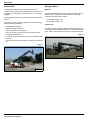
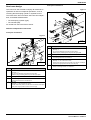
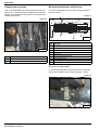
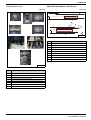
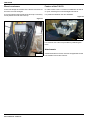
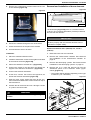
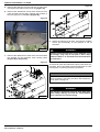
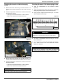
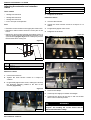
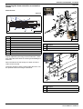
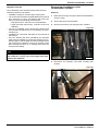
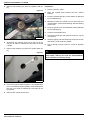
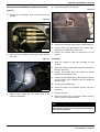
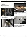
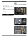
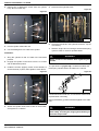
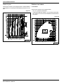
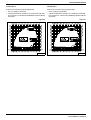
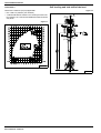
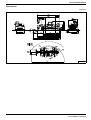
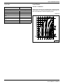
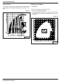
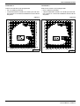
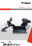
EN
T40140
Service Manual V2 Boom
S/N 3603 12001
& above
T40170
S/N 3609 12001
& above
1
04
S0
4852040-EN (08-03)
© Bobcat Europe, 2003
CONTENTS
CONTENTS
IMPORTANT
This document provides specific information for the new version of the T40140 and T40170 telescopic handlers. Read this document for a better understanding of the advantages this version has over previous versions of telescopic handlers.
NEW BOOM ..................................................................................................................................................................... 1
SPECIFIC PROCEDURES - V2 BOOM......................................................................................................................... 11
SPECIFICATIONS ......................................................................................................................................................... 27
T40140 SPECIFICATIONS .................................................................................................................................. 27
T40170 SPECIFICATIONS .................................................................................................................................. 35
Bobcat T40140 / T40170
Service Manual - V2 Boom
II
NEW BOOM
NEW BOOM
Introduction .......................................................................................................................................................................2
Stronger boom ..................................................................................................................................................................2
Material ...................................................................................................................................................................2
Counter jib...............................................................................................................................................................2
New boom design .............................................................................................................................................................3
Different components of the boom..........................................................................................................................3
Telescoping cylinder ...............................................................................................................................................6
Cassette..................................................................................................................................................................6
Pads ..................................................................................................................................................................................7
New concept ...........................................................................................................................................................7
Lubricator built into the pads...................................................................................................................................7
Glide angle iron for the pads...................................................................................................................................7
Compensation cylinder......................................................................................................................................................8
Mechanical kinematics of the boom ..................................................................................................................................8
Tensioner for lower chains......................................................................................................................................8
Hooking up the chains ............................................................................................................................................9
Hydraulic kinematics of the boom .....................................................................................................................................9
Electric enclosure............................................................................................................................................................10
Feature of the T40170.....................................................................................................................................................10
Attachments ....................................................................................................................................................................10
1
Bobcat T40140 / T40170
Service Manual - V2 Boom
NEW BOOM
Introduction
Stronger boom
The principal change that characterises both new
machines is the design and construction of a new boom. It
is simple but heavy-duty for machines in the 14-17 meter
category.
Material
A high elastic limit (HEL) steel is used to build the new generation boom, resulting in a 28% increase in strength
compared to the previous version.
The new boom uses the most advanced technology on the
market.
• V1 strength: 36 kg/ mm²
• V2 strength: 50 kg/ mm²
The simple, modern design integrates a new technology
with the following features:
Counter jib
• Compensation cylinder.
A counter jib was created to keep the boom perfectly horizontal when fully extended under load, to avoid the "fishing
pole" effect. This technique is used in crane construction.
• Reduced weight of booms.
• 78% less pressure on the pads.
• 100% increase of pad / boom contact surface area.
Figure 2
• Simplified maintenance
• A counter jib allowing the boom to be horizontal under
full load.
• Change of location of the electric enclosure of the boom
tip.
Figure 1
S0043
S0042
Bobcat T40140 / T40170
Service Manual - V2 Boom
2
NEW BOOM
New boom design
Front part of element 2
Figure 4
This new boom was created to simplify all maintenance
operations as well as exceptional operations, such as
removing the telescoping cylinder or hydraulic hoses.
The inside of the boom is broken down into two independent, removable subassemblies:
• The telescoping cylinder (right).
"
• The cassette (left).
As viewed from the back of the machine.
Different components of the boom
Front part of element 1
Figure 3
S0102
"
Ref.
1
Upper and lower pads
• Quantity = 4
• Do not insert adjusting shims with the lower pads.
• Reduce play by inserting shims only with the upper pads.
2
Adjusting shims
3
Boom retracting chain
• Connecting element 2 and element 4.
4
Side pads
• Quantity = 4, two of which are 13mm.
• Install 13mm thick pads on the left side of the caisson and adjust
with pads of appropriate thickness to limit the play.
5
Chain rollers for boom extension
• Chains connecting element 1 to element 3.
S0101
!
Ref.
Description
Description
1
Upper and lower pads
• Quantity = 4
• Do not insert adjusting shims with the lower pads.
• Reduce play by inserting shims only with the upper pads.
2
Adjusting shims
3
Boom retracting chains
• Connected to element 1 and element 3.
4
Side pads
• Quantity = 4, two of which are 13mm.
• Install 13mm thick pads on the left side of the caisson and adjust
with pads of appropriate thickness to limit the play.
3
Bobcat T40140 / T40170
Service Manual - V2 Boom
NEW BOOM
Rear part of element 2
Front part of element 3
Figure 5
Figure 6
$
!
"
S0104
S0103
Ref.
Ref.
1
Description
Side pads
• Quantity = 2, one of which is 13mm.
• Install the 13mm thick pad on the left side of the caisson and
adjust to the right with a pad of appropriate thickness to limit the
play.
2
Upper pads.
• Compensate for play by inserting shims between the upper pads
and the caisson.
3
Right side pad
4
No shimming on the lower side parts for all elements.
5
Lower pads
• Do not insert adjusting shims.
WARNING
Some (6) retaining screws (Allen) are specific: the
height of the head is lower (screws for side pads
and for upper and lower pads).
Make sure to put them back in the right place.
Bobcat T40140 / T40170
Service Manual - V2 Boom
4
Description
1
Upper and lower pads
• Quantity = 4
• Do not insert adjusting shims with the lower pads.
• Reduce play by inserting shims only with the upper pads.
2
Chain rollers for boom extension
• Chains connecting element 2 to element 4.
3
Side pads
• Quantity = 4, two of which are 13mm.
• Install 13mm thick pads on the left side of the caisson and adjust
with pads of appropriate thickness to limit the play.
NEW BOOM
Rear part of element 3
Rear part of element 4
Figure 7
Figure 8
%
!
!
$
%
"
#
Ref.
#
S0105
Ref.
Description
1
Upper and lower pads
• Quantity = 4
• Do not insert adjusting shims with the lower pads.
• Reduce play by inserting shims only with the upper pads.
2
Extension chains
• Connecting element 1 to element 3.
3
Side pads
• Quantity = 2, one of which is 13mm.
• Install the 13mm thick pad on the left side of the caisson and
adjust to the right with a pad of appropriate thickness to limit the
play.
"
S0106
Description
1
Side pads
• Quantity = 2, one of which is 13mm.
• Install the 13mm thick pad on the left side of the caisson and
adjust to the right with a pad of appropriate thickness to limit the
play.
2
Extension chains
• Connecting element 2 to element 4.
3
Upper pads.
• Compensate for play by inserting shims between the upper pads
and the caisson.
4
Right side pad
4
No shimming on the lower side parts for all elements.
5
No shimming on the lower side parts for all elements.
5
Lower pads
• Do not insert adjusting shims.
6
Lower pads
• Do not insert adjusting shims.
WARNING
WARNING
Some (6) retaining screws (Allen) are specific: the
height of the head is lower (screws for side pads
and for upper and lower pads and securing
chains).
Some (7) retaining screws (Allen) are specific: the
height of the head is lower (screws for side pads
and for upper and lower pads and attaching chain
hookup).
Make sure to put them back in the right place.
Make sure to put them back in the right place.
5
Bobcat T40140 / T40170
Service Manual - V2 Boom
NEW BOOM
Telescoping cylinder
Cassette.
Rear part of cylinder - attachment to element 1
The concept of “cassette” is unique on the market in that it
collects together all of the boom's hoses and electrical
cables.
Figure 9
Figure 11
S0107
S0047
This unique, patented technology avoids having to completely remove the boom during inspections or technical
problems. The hoses are simply disconnected at the front
and back of the boom and the whole cassette removed.
This provides a significant time gain during after-sale
service.
Front part of cylinder
Figure 10
Inside this cassette, a separator has been built in to
separate:
• the hydraulic function
• the electrical function
Figure 12
S0108
2
Ref.
Bobcat T40140 / T40170
Service Manual - V2 Boom
6
3
4 5 6 1
7
Description
1
Cassette inside which the chains and hoses turn.
2
Extend boom
3
Retract boom
4
Tilt?
5
Pitch?
6
Attachment (male coupling)
7
Attachment (female coupling)
S0046
NEW BOOM
Pads
Lubricator built into the pads
New concept
The upper and lower pads are equipped with a built-in
lubricator, considerably facilitating their maintenance.
The new pads have been simplified. The total support surface has been quadrupled compared to the older models.
Description
New
Old
Pad length
90 mm
200 mm
Pad width
-
50 mm
Figure 14
Figure
Height
Support surface
60 mm
17 mm
2,660 mm²
10,000 mm²
Previously the wear pads were placed in the corners of the
boom. Now they are placed on the sides of the boom.
S0049
Figure 13
NEW
Glide angle iron for the pads
An angle iron is welded to the lower part of the boom elements so that the glide of the pad and the contact surface
are perfectly in the same plane.
OLD
Figure 15
S0048
This method allows the contact surface of the boom on the
pads to be considerably increased. This results in a 78%
decrease in pressure (the whole surface of the pad is
used) on the pad compared to the previous arrangement.
In the present system, the pads no longer fit closely around
the boom elements, but now help guide it. The effort
needed for the telescoping function, therefore, has been
divided by two!
S0050
7
Bobcat T40140 / T40170
Service Manual - V2 Boom
NEW BOOM
Compensation cylinder
Mechanical kinematics of the boom
This is mounted beside the raising/lowering cylinder. Its
purpose is to regulate the flow of hydraulic fluid of the tilt
cylinder when the boom is being raised or lowered. (Horizontality of the forks).
The boom's kinematics have not been changed from the
previous version.
Figure 17
$
Figure 16
#
"
!
$
'
&
Ref.
1
Ref.
1
2
2
S0051
Description
Compensation cylinder
Lift cylinder
%
S0117
Description
1
Element 1
2
Element 2
3
Element 3
4
Element 4
5
Chain rollers
6
Chain tension adjustment points
7
Boom extension chains
8
Boom retracting chains
9
Chain rollers
Tensioner for lower chains
To facilitate the adjustment of the lower chains, tensioners
have been installed in front of boom elements 1 and 2.
Figure 18
S0052
Bobcat T40140 / T40170
Service Manual - V2 Boom
8
NEW BOOM
Hydraulic kinematics of the boom
Hooking up the chains
Figure 19
Figure 20
1
!
"
$
3
#
2
!
4
5
%
Ref.
6
7
8
Ref.
"
&
'
S0118
Description
1
Element 1
2
Element 2
3
Element 3
4
Element 4
5
Cassette
6
Telescoped boom
7
Retracted boom
8
Hoses in chains?
9
Rigid?
S0055
Description
1
Hookup for 1 chain located inside element 4
2
Hookup for 1 chain located under the boom
3
Attachment of the 4 chains on element 1
4
Hookup for 4 chains located on element 3
5
Hookup for 2 chains located on element 4 and inside element 3
6
Hookup of retraction chains
7
Hookup of retraction chains located on element 3
8
Hookup of extension chains located on element 1
9
Bobcat T40140 / T40170
Service Manual - V2 Boom
NEW BOOM
Electric enclosure
Feature of the T40170
In this new design the location of the electric enclosure at
the boom end was changed.
In order to have a true 17 meters on stabilisers as well as
on tyres, a 500 kg front counterweight was built in.
It is now located on the left side of the boom tip. Previously
it was positioned under the boom tip.
It is positioned between the two stabilisers.
Figure 22
Figure 21
S0053
For removal, two holes are provided for positioning the
forks.
Attachments
All attachments from former versions are applicable for the
new models T40140 and T40170.
S0054
Bobcat T40140 / T40170
Service Manual - V2 Boom
10
SPECIFIC PROCEDURES - V2 BOOM
SPECIFIC PROCEDURES - V2 BOOM
Safety ..............................................................................................................................................................................12
Removal and installation of the chains/hoses cassette...................................................................................................12
Removal................................................................................................................................................................12
Installation.............................................................................................................................................................13
Removal and installation of boom elements ...................................................................................................................13
Remove elements 2 and 3 (T40140) or 2, 3 and 4 (T40170)................................................................................13
Checking the tension of the telescoping chains ..............................................................................................................15
Checking the wear of the telescoping chains..................................................................................................................15
Adjusting the extension and retraction chains.................................................................................................................16
Tools needed ........................................................................................................................................................16
First .......................................................................................................................................................................16
Retraction chains ..................................................................................................................................................16
Extension chains...................................................................................................................................................16
Replacing the boom retraction or extension chains ........................................................................................................17
Work on rear of boom ...........................................................................................................................................18
Work on front of boom ..........................................................................................................................................18
Replacing boom pads .....................................................................................................................................................18
Parts......................................................................................................................................................................18
Front pads of the elements ...................................................................................................................................19
Rear pads of the elements....................................................................................................................................20
Important reminder................................................................................................................................................21
Removal and installation of the compensation cylinder ..................................................................................................21
Removal................................................................................................................................................................21
Installation.............................................................................................................................................................22
Removal and installation of the tilt cylinder .....................................................................................................................23
Removal................................................................................................................................................................23
Installation.............................................................................................................................................................23
Removal and installation of the lift cylinder .....................................................................................................................24
Removal................................................................................................................................................................24
Installation.............................................................................................................................................................25
Removal and installation of the telescoping cylinder ......................................................................................................25
Removal................................................................................................................................................................25
Installation.............................................................................................................................................................26
11
Bobcat T40140 / T40170
Service Manual - V2 Boom
SPECIFIC PROCEDURES - V2 BOOM
Safety
Removal and installation of the chains/hoses
cassette
Removal
WARNING
1. Disconnect the hydraulic lines at the front and rear of
the boom, as well as the electrical connectors
[Figure 23] and [Figure 24].
All handling operations must be done with maximum safety, including the slinging and chocking of
removed components.
Figure 23
S0068
Figure 24
S0069
2. Remove the attachment screws from the flat face to
which the elbow connections are attached
[Figure 24].
3. Fully extend the boom and remove the 2 attachment
screws located on top of the last element holding the
lines rigid, except for the screw located at the head of
the boom [Figure 23].
4. Retract the boom gently and remove the remaining
screw [Figure 23].
Bobcat T40140 / T40170
Service Manual - V2 Boom
12
SPECIFIC PROCEDURES - V2 BOOM
Removal and installation of boom elements
5. Remove the 2 attachment screws located at the rear
of the cassette [Figure 25].
Figure 26
Figure 25
"
!
S0071
The kinematics [Figure 26] refers to a 4-element boom
(T40170). The 3-element kinematics (T40140) is identical,
but with one less element.
IMPORTANT
S0070
Place the machine in an environment where work can
be done properly and the removed elements can be
handled in complete safety.
6. Extract the cassette through the rear of the boom.
7. Check the thickness of the pad of the cassette
8. Proceed with the work to be done.
Remove elements 2 and 3 (T40140) or 2, 3 and 4
(T40170)
Installation
1. Raise the boom until it is horizontal.
1. Place the cassette inside the boom.
2. Remove the "chains-hoses" cassette. See “Removal
and installation of the chains/hoses cassette” on
page 12.
2. Install the attachment screws for the rigid lines located
at the head of the boom [Figure 23].
3. Remove the telescoping cylinder. See “Removal and
installation of the telescoping cylinder” on page 25.
3. Attach the cassette in element No. 3 [Figure 25].
4. Connect the hoses to the rigid lines and attach the
support to the side faces of element 1 [Figure 24].
4. Remove the 2 or 4 nuts and locknuts (a) from the
attachment points of the extension chains (upper
chains) [Figure 27].
5. Connect the electrical harnesses.
• The number will be different depending on the type
of machine (3 or 4 elements).
6. At the front, connect the hoses to the rigid lines, as
well as the electrical harnesses [Figure 23].
Figure 27
7. Start the motor, gently extend the boom all the way,
then install the 2 attachment screws located on top of
the last element.
8. Activate the tilt movement and run it through a series
of cycles to check for leaks.
WARNING
a
Use Loctite on the threads when tightening the
screws.
S0109
13
Bobcat T40140 / T40170
Service Manual - V2 Boom
SPECIFIC PROCEDURES - V2 BOOM
5. Remove the split pins from the link pins on chain rods
and stretch the chains on the boom (b) [Figure 27].
Figure 30
6. Remove the attachment screws from the boom front
pads and take out the pads, marking their position if
they are going to be reinstalled [Figure 28].
Figure 28
S0111
8. Attach the element at its front, and using a handling
device pull horizontally on the element or set of
elements.
S0072
WARNING
Caution: when the element or set of elements is out
far enough, sling it by its rear part so that it stays
balanced when it is released from the fixed boom
(or element 1).
7. Remove the attachment screws at the rear and inside
the element for the retraction chain hookup parts
[Figure 29] et [Figure 30].
Figure 29
The removal of the other elements is done in the same way
as before, but it is important to place all elements on a stable structure in order to prevent any accidents.
IMPORTANT
The reinstallation and adjustment of the pads will be
done according to a specific procedure. See “Replacing
boom pads” on page 18.
WARNING
The handling operations must be done with maximum safety, making sure that the subassemblies
to be removed are correctly slung.
S0110
Bobcat T40140 / T40170
Service Manual - V2 Boom
14
SPECIFIC PROCEDURES - V2 BOOM
Checking the tension of the telescoping
chains
Checking the wear of the telescoping chains
1. Take the measurement on the extension chains
(exterior).
1. Retract the boom all the way, hold the control for a
moment, then block the boom so that it can not come
out.
2. Take the measurement when the boom is completely
deployed (telescoped) in the horizontal position.
2. Check the tightness of the tension screw of each of the
two extension chains.
3. Using a vernier caliper measure the length L of 10 links
at the outside of the link pin.
• The torque should be between 2.5 and 3 daN.m.
Figure 33
• Both chains should have identical tension.
Figure 31
1
2
3
4
5
6
7
8
9
10
L
93788
WARNING
The measurement must be taken as shown in the
diagram, at the outside of the pins of the chain.
S0073
4. The wear is considered normal as long as L is less
than 169.50 mm.
Figure 32
5. If L is equal to or more than that value, the chains,
pins, rollers, tension rods and attachment screws
MUST be replaced.
IMPORTANT
• Each time you measure L, write down the date it is
checked and the number of hours on the machine.
S0074
3. Run the boom all the way out, hold the control for a
moment, then block the boom so that it can not retract.
4. Check the tightness of the tension screw of each of the
two return chains.
• The torque should be between 2.5 and 3 daN.m.
• Both chains should have identical tension.
IMPORTANT
The nuts should screw freely onto the tensioners.
15
Bobcat T40140 / T40170
Service Manual - V2 Boom
SPECIFIC PROCEDURES - V2 BOOM
Adjusting the extension and retraction
chains
Ref.
Tools needed
Description
1
Adjusting retraction chain of element 4
2
Adjusting retraction chain of element 3
4. Retighten the locknuts
• 1 wedge 190 mm thick
• 1 wedge 280 mm thick
Extension chains
• 1 wedge 300 mm thick
• 2 x 27 mm open-end spanners
1. Unscrew the locknuts.
First
2. Tighten the chain tension screws to a torque of 1.8
daN.m.
• Extension chains located on the upper part of the boom.
3. Progressively tighten each screw.
• Retraction chains located under the lower part of the
boom.
4. Retighten the locknuts.
• Retract the boom while inserting the wedges (insert a
280 mm wedge (300-20=280) between elements 1 and
2) as shown in [Figure 34] and use 2 clamps to prevent
the elements from coming out.
Figure 36
Figure 34
!
#
!
&
"
'
S0076
S0119
Ref.
Description
1-4
Element 1-4
5
Figure 37
Welded plate (20 mm)
Retraction chains
1. Unscrew the locknuts.
2. Tighten the chain tension screws to a torque of
3 daN.m.
3. Progressively tighten each screw, making sure to keep
the tensioner perfectly parallel to the belt of the
element [Figure 35].
S0077
Figure 35
5. Remove the clamps.
1
2
6. Telescope out slightly to release the wedges.
7. Telescope the boom all the way in and out several
times in the horizontal position.
WARNING
It is important to adhere to the indicated tension
torques. The working life of the chains will be
affected and therefore safety.
S0075
Bobcat T40140 / T40170
Service Manual - V2 Boom
16
SPECIFIC PROCEDURES - V2 BOOM
Replacing the boom retraction or extension
chains
Figure 39
General views
Figure 38
$
#
"
%
!
$
&
Ref.
'
S0120
Description
1
Element 1
2
Element 2
3
Element 3
4
Element 4
5
Chain rollers
6
Chain tension adjustment points
7
Boom extension chains
8
Boom retracting chains
9
Chain rollers
S0112
Ref.
Description
1
Front attachment of the extension chains
2
Front attachment of the retraction chains
Figure 40
The extension chains, located at the top of the boom, can
only be replaced by removing the boom elements. Therefore, follow the instructions for removing and installing the
elements.
When the element is free enough, the other end of the
chain can be removed.
The boom retraction chains, located under the boom, can
be replaced without removing the elements.
S0113
Ref.
17
Description
1
Interior attachment of the extension chains
2
Interior attachment of the retraction chains
Bobcat T40140 / T40170
Service Manual - V2 Boom
SPECIFIC PROCEDURES - V2 BOOM
Work on rear of boom
Replacing boom pads
1. If the telescoping cylinder has to be removed. See
“Removal and installation of the telescoping cylinder”
on page 25.
Replacing the pads can be done without removing the
boom elements.
Parts
2. Remove the attachment of the chain hookup part
located inside the boom element.
Designation
Upper & lower pad
3. Remove the pin from the shaft holding the chain links
with their attachments.
4. Hook the new chains to the end of the old ones.
Work on front of boom
1. Remove the front mounting and uncouple the chains
from the mounting parts.
2. Pull and remove the chains until the new chains
appear.
WARNING
The threads of the screws shown in[Figure 40]
must be doped with Loctite and tightened to a
torque of 3 daN.m.
It is important to adhere to the indicated tension
torques. The working life of the chains will be
affected and therefore safety.
See
24
(depending on No. of
elements)
[Figure 42]
1 mm shim for long pad
As needed
shim for long pad 2 mm
As needed
shim for long pad 3 mm
As needed
Side pad 11 mm
As needed
[Figure 41]
Side pad 12 mm
As needed
[Figure 41]
13mm side pad
9 mount on left side
[Figure 41]
Side pad 14 mm
As needed
[Figure 41]
Side pad 15 mm
As needed
[Figure 41]
Screw H8-15
38
(depending on No. of
elements)
[Figure 43]
Screw H8-20
14
(depending on No. of
elements)
[Figure 43]
Screws for side pads
CHC M8-10-CL8.8
12
(depending on No. of
elements)
[Figure 43]
Screws for upper and lower
rear pads
CHC M8-16-CL10.9 DIN7984
36
(depending on No. of
elements)
[Figure 43]
Washer
100
(depending on No. of
elements)
3. Re-attach the new chains to their respective hookups.
4. Attach the chain hookups to their respective mounting
points.
Quantity
Figure 41
All handling operations must be done with maximum safety, including the slinging and chocking of
removed components.
S0080
Figure 42
S0081
Bobcat T40140 / T40170
Service Manual - V2 Boom
18
SPECIFIC PROCEDURES - V2 BOOM
Figure 43
Figure 45
Front part of sliding element No. 1
S0082
Front pads of the elements
Removing
1. Remove the attachment screws [Figure 44] from the
upper pads and pull them out. There are 2 or 3
attachment screws, depending on the element.
Figure 44
Front part of sliding element No. 2
S0084
2. Caution - shims may come out with the pads.
3. Remove the attachment screws from the side pads
and extract the pads by lifting and pulling for the lower
sides, and by raising and pulling for the upper sides.
Front part of sliding element No. 3
4. Using a hoist, sling the front part of the element and
raise it in order to release the lower part to extract the
pads.
Installation
1. With front of boom raised in order to slide in the lower
pads (to be mounted without adjustment shim), apply
Loctite to the threads of the screws and tighten to a
torque of 3 daN.m.
2. Install the front part of the boom and engage the 13mm
thick side pads on the left part of the element (viewed
from rear of boom) [Figure 45], then tighten the
screws using the procedure indicated below.
S0114
19
Bobcat T40140 / T40170
Service Manual - V2 Boom
SPECIFIC PROCEDURES - V2 BOOM
3. Adapt the right side pads by a thickness that allows
them to be in contact with the element of the sliding
boom, then tighten the screws using the procedure
indicated below.
Installation
1. Prepare the lower pads. The number depends on the
type of machine (T40140 or T40170).
Figure 46
4. Engage the upper pads, using the necessary shims to
make contact with the element of the sliding boom,
then tighten the screws with a torque of 3 daN.m using
Loctite on the threads.
WARNING
Note: the screws of the side pads should be tightened as follows:
• tighten until it makes contact with the caisson,
then tighten an additional 1/8th turn.
Don't forget to reinstall the lubricators on the upper
and lower pads.
S0115
2. Put them in place and tighten the attachment screws
(apply Loctite to the threads and tighten to 3 mKg). Do
not insert adjusting shim. Take the 13mm side pads
and put them in place on the left part of the elements
(side toward the cabin), insert and tighten the
attachment screws 1/8th turn after the screw makes
contact with the caisson.
Rear pads of the elements
Removing
1. Retract the boom, taking care to leave the pad
attachment screws accessible.
2. Remove the chains-hoses cassette. See “Removal
and installation of the chains/hoses cassette” on
page 12.
3. Determine the amount of right side space and select
the nearest thickness of pad so that it is in close
contact with the boom element; insert and tighten the
attachment screws 1/8th turn after the screw makes
contact with the caisson.
3. Remove the telescoping cylinder. See “Removal and
installation of the telescoping cylinder” on page 25.
4. Remove the attachment screws from the pads.
4. Determine the amount of free space between the
elements [Figure 47] and select the upper pads, and
shims if necessary, so that they are in close contact
with the boom element; tighten the attachment screws
(apply Loctite to the screw threads and tighten to
3 daN.m).
5. Extract the lower and side pads from each element.
6. Using a hoist, raise the front part of the boom in order
to free up the upper rear pads.
7. Remove the attachment screws from the pads.
Figure 47
8. Extract the upper pads.
S0085
Bobcat T40140 / T40170
Service Manual - V2 Boom
20
SPECIFIC PROCEDURES - V2 BOOM
Removal and installation of the
compensation cylinder
Important reminder
The reassembly of the elements will be done with rear
shimming carried out as follows:
Removal
• Installation of pads in the lower part, without shim.
1. Raise the boom high enough to allow the headshaft to
clear the cabin.
• The screws used to attach the pads MUST be those that
were removed, or if they are replaced with new ones
they must have the following characteristics.
2. Secure the boom in that position.
• Side pad screws - CHC M.8-10 CL8.8 DIN7984
3. Remove the screws connecting the two cylinders.
• Upper and lower pad screws - CHC M.8-16 CL10.9
DIN7984
Figure 48
• The use of standard screws with thicker heads could
have harmful consequences on the operation of the kinematics [3].
• Installation of 13mm thick side pads on the left side of
the element.
• Once the element has been reinstalled, the right side
pads must be adapted by a thickness relative to the remaining space, and the pads and shims installed at the
top to reduce the clearance as much as possible, while
also ensuring that there is no sticking point when the
structures are sliding.
WARNING
In every case, the adjustment of clearance between
the elements is done only at the upper and right
parts of the elements.
S0086
4. Disconnect the hydraulic lines after marking their
position.
Figure 49
S0087
21
Bobcat T40140 / T40170
Service Manual - V2 Boom
SPECIFIC PROCEDURES - V2 BOOM
Installation
5. Remove the retaining ring from the cylinder head pin
[2].
1. Put the cylinder in place.
Figure 50
2. Mate the cylinder base bearing with the chassis
bearing.
3. Push the cylinder base pin, put the washer on followed
by the retaining ring.
4. Manually extend the cylinder rod out and mate the
compensation cylinder head bearing with the bearing
of the boom.
5. Push the pin back out and install the washer followed
by the retaining ring.
6. Connect the hydraulic lines.
7. Check the fluid level in the hydraulic reservoir. Top off
if necessary.
S0088
8. Start the engine and activate the tilt movement in both
directions in order to fill the cylinder.
6. Supporting the cylinder, push the pin but not all the
way out, in order to maintain the connection to the lift
cylinder.
9. Run it through several cycles to check for possible
leaks.
7. Remove the retaining ring from the cylinder base pin
[4].
WARNING
Figure 51
The handling operations must be done with maximum safety, making sure that the subassemblies
to be removed are correctly slung.
S0089
8. Pull out the cylinder base pin (same - the cylinder base
pin is connected to the lift cylinder), without taking it all
the way out in order to maintain the connection to the
lift cylinder.
9. Remove the cylinder with a hoist.
Bobcat T40140 / T40170
Service Manual - V2 Boom
22
SPECIFIC PROCEDURES - V2 BOOM
Removal and installation of the tilt cylinder
4. Extract the cylinder rod head pin.
Figure 54
Removal
1. Disconnect the hydraulic lines connected to the tilt
cylinder.
Figure 52
S0092
5. Remove the retaining ring from the cylinder base pin.
6. Using a screw ring (Ø10x150) in the cylinder base,
support the cylinder with a chain hoist.
S0090
7. Remove the cylinder base pin and lower it to the
ground.
2. Remove the pin retaining screw [2] from the cylinder
rod head.
Installation
Figure 53
1. Sling the cylinder at the point provided for that
purpose.
2. Raise the cylinder, passing it through the lower part of
the tip of the boom.
3. Engage the cylinder base pin, install the washer
followed by the retaining ring.
4. Position the rod head facing the pin bearing located on
the tool holder yoke, engage the pin and install the
locking screw.
5. Connect the hydraulic lines.
6. Check the level in the hydraulic system. Top off if
necessary.
S0091
7. Remove the sling.
3. Using a sling, attach the tool holder yoke in the
maximum tilt position.
8. Start the engine and run through several cycles in
order to check for possible leaks.
WARNING
All handling operations must be done with maximum safety, including the slinging and chocking of
removed components.
23
Bobcat T40140 / T40170
Service Manual - V2 Boom
SPECIFIC PROCEDURES - V2 BOOM
Removal and installation of the lift cylinder
5. Remove the retaining ring from the cylinder head pin .
Figure 57
Removal
1. Raise the boom high enough to allow the headshaft to
clear the cabin.
2. Secure the boom in that position.
3. Remove the screws connecting the two cylinders.
Figure 55
S0095
6. Support the cylinder and remove the pin (caution: the
compensation cylinder is connected by this pin to the
lift cylinder)).
7. Remove the retaining ring from the cylinder base pin .
Figure 58
S0093
4. Disconnect the hydraulic lines connected to the valve,
after marking their position.
Figure 56
S0096
8. Pull out the cylinder base pin (same - the cylinder base
pin is connected to the compensation cylinder)).
9. Remove the cylinder with a hoist.
S0094
Bobcat T40140 / T40170
Service Manual - V2 Boom
24
SPECIFIC PROCEDURES - V2 BOOM
Removal and installation of the telescoping
cylinder
Installation
1. Put the cylinder in place.
Removal
2. Mate the cylinder base bearing with the chassis
bearing.
1. Disconnect the lines connected to the telescoping
cylinder valve.[1]
3. Engage the cylinder base pin, install the washer
followed by the retaining ring.
Figure 59
4. Connect they hydraulic lines to the cylinder's valve,
according to their initial position.
5. Check the fluid level in the hydraulic reservoir. Top off
if necessary.
6. Start the engine and control the lift function until the
rod bearing mates with the boom bearing.
7. Engage the pin and install the washer followed by the
retaining ring.
8. Run it through several cycles to check for possible
leaks.
WARNING
S0097
All handling operations must be done with maximum safety, including the slinging and chocking of
removed components.
2. Remove the attachment screw from the cylinder head:
Ø6 mm Allen key.
Figure 60
S0098
Figure 61
S0099
25
Bobcat T40140 / T40170
Service Manual - V2 Boom
SPECIFIC PROCEDURES - V2 BOOM
3. Remove the 4 attachment screws from the cylinder
body: Ø14 mm Allen key.
5. Reconnect the hydraulic lines.
Figure 64
Figure 62
S0097
S0100
6. Check the fluid level in the hydraulic reservoir. Top off
if necessary.
4. Pull the cylinder toward the rear.
7. Start the engine and run through several telescoping
cycles in order to check for possible leaks.
5. Use a handling device to extract the cylinder.
Installation
WARNING
1. Sling the cylinder so that it is held in the horizontal
position.
Apply Loctite to the threads when tightening the
screws.
2. Engage the cylinder in the boom until it is in contact
with its attachment points.
The part shown in [Figure 65] is a skid that enables the
telescoping cylinder shaft to be held on the caisson.
3. Install the screws, applying Loctite to the threads, to
secure the body in place, then tighten to 29.5 daN.m.
Figure 65
Figure 63
S0116
Its limit of thickness is 50 mm, so it should be checked and
replaced when necessary.
During reassembly, grease should be applied to the slide
part.
S0100
4. Attach the cylinder head, with Loctite on the threads,
and tighten to 2.5 daN.m.
Bobcat T40140 / T40170
Service Manual - V2 Boom
WARNING
All handling operations must be done with maximum safety, including the slinging and chocking of
removed components.
26
T40140 SPECIFICATIONS
SPECIFICATIONS
T40140 SPECIFICATIONS
Introduction .....................................................................................................................................................................28
Detailed specifications ....................................................................................................................................................28
General .................................................................................................................................................................28
Hydrostatic Transmission......................................................................................................................................28
Cycle time .............................................................................................................................................................29
Load Charts.....................................................................................................................................................................29
T40140 on stabilisers............................................................................................................................................29
T40140 on tyres ....................................................................................................................................................30
Platform load charts ........................................................................................................................................................30
Load Chart 1 .........................................................................................................................................................30
Load Chart 2 .........................................................................................................................................................31
Load Chart 3 .........................................................................................................................................................31
Load Chart 4 .........................................................................................................................................................32
Self leveling and side shift of the load.............................................................................................................................32
Dimensions .....................................................................................................................................................................33
27
Bobcat T40140 / T40170
Service Manual - V2 Boom
T40140 SPECIFICATIONS
Introduction
Hydrostatic Transmission
As a result of the design and construction of the new
boom, the load charts of the T40140 have been considerably improved:
Reference
Value
Hydrostatic pump
• Greater work area for the same capacity as before.
Manufacturer
• Greater elevation heights
Pump type
• …
Location
SAUER
Variable displacement pump
On the flywheel housing of the
diesel engine
Displacement
From 0 to 75 cm³
Maximum operating pressure
Detailed specifications
450 ± 20 bar
Hydrostatic engine
General
Manufacturer
SAUER
Pump type
Reference
Location
Value
On stabilisers
Nominal capacity
Attached to the transfer case of
the front axle
Displacement
From 160 to 38 cm³
Maximum operating pressure
4000 Kg
Max. elevation height
Variable displacement pump
13610 mm
450 ± 20 bar
Electronic regulation
Capacity at max height
4000 Kg
Electronics module
Max. reach
9700 mm
Location
Capacity at max. reach
1300 Kg
SAUER type SUSMIC
Under the moulding, right side in
cabin
Pump equipment
On tyres
Max. elevation height
13430 mm
Manufacturer
CASAPPA
Gear pump
Capacity at max height
2500 Kg
Pump type
Max. reach
9800 mm
Location
Capacity at max. reach
Attached to the power takeoff of
the hydrostatic pump
250 Kg
Empty weight
Displacement
10010 Kg
Maximum operating pressure
C2DL Self Leveling - Side Shift of the Load
Self leveler alone
12° / 12°
Side shift of the load
1400 mm
DUNLOP
Model
Manufacturer
CASAPPA
Pump type
Gear pump
Location
Standard tyres
Manufacturer
240 ± 20 bar
Steering and ventilator pump
4° / 4°
Self leveler + Stabilisers
44 cm³
Attached to the power takeoff of
the equipment pump
Displacement
400/80 x 24'' 153 B
16 cm³
Maximum operating pressure
Brake
160 ± 20 bar
Capacities
Engine brake
Hydrostatics
Hydraulics reservoir
72 litres
Service Brake
On front axle
Hydraulics system (full)
140 litres
Numer of discs
3x2
Coolant circuit
17 litres
On front axle
Diesel fuel tank
140 litres
Parking and emergency brake
Axles and reduction gears (front / rear)
Engine
Manufacturer
Model
Displacement
PERKINS
4 cylinders / 3990 cc
FASTRAM direct injection
Cooling system
Water
Max. torque.
Bobcat T40140 / T40170
Service Manual - V2 Boom
11.9 / 11.4 litres
6.5 litres
Angle and effort
1004.40T (Turbo)
Type of injection
Power at 2200 RPM (ISO 14376)
Engine oil
Total angle of rotation
74.5 Kw / 100 CV @ 2200 RPM
402 Nm at 1400 RPM
28
125°
Crowding force
5000 Da.N
Pulling effort
5100 Da.N
T40140 SPECIFICATIONS
Load Charts
Cycle time
Reference
T40140 on stabilisers
Value
Lowering
7.2 s
Chart for the machine (V2) equipped with 4 identical DUNLOP 400/80 x 24 153 B tyres with inflation pressure of 4.25
bars and stabilisers lowered completely down.
Telescoping retraction at maximum reach
12.4 s
Figure 66
Cycle time under load at maximum rating
Telescoping retraction at maximum
height
11 s
Telescoping extension at maximum reach
19 s
Telescoping extension at maximum
height
19 s
Crowding
4.6 s
Tilt
1,12
13 s
13,61
4s
0.5m
6,22
0,42
0,26
9,70
Lifting
S0029
29
Bobcat T40140 / T40170
Service Manual - V2 Boom
T40140 SPECIFICATIONS
T40140 on tyres
Platform load charts
Chart for the machine (V2) equipped with 4 identical DUNLOP 400/80 x 24 153 B tyres with inflation pressure of 4.25
bars.
Load Chart 1
Chart for the machine (V2) equipped with:
Figure 67
• the 1.2 m² platform (oriented)
1,85
• 4 identical DUNLOP 400/80 x 24 153 B tyres with inflation pressure of 4.25 bars and stabilisers lowered all the
way down
13,43
Figure 68
0.5m
6,16
0,06
9,80
9,48
0,19
S0030
S0056
Bobcat T40140 / T40170
Service Manual - V2 Boom
30
T40140 SPECIFICATIONS
Load Chart 2
Load Chart 3
Chart for the machine (V2) equipped with:
Chart for the machine (V2) equipped with:
• the 4 m platform (oriented)
• the 5 m platform (oriented)
• 4 identical DUNLOP 400/80 x 24 153 B tyres with inflation pressure of 4.25 bars and stabilisers lowered all the
way down
• 4 identical DUNLOP 400/80 x 24 153 B tyres with inflation pressure of 4.25 bars and stabilisers lowered all the
way down
Figure 69
Figure 70
S0058
S0057
31
Bobcat T40140 / T40170
Service Manual - V2 Boom
T40140 SPECIFICATIONS
Self leveling and side shift of the load
Load Chart 4
Chart for the machine (V2) equipped with:
Figure 72
• the 4 and 5 m platform (not oriented)
• 4 identical DUNLOP 400/80 x 24 153 B tyres with inflation pressure of 4.25 bars and stabilisers lowered all the
way down
Figure 71
S0059
S0060
Bobcat T40140 / T40170
Service Manual - V2 Boom
32
T40140 SPECIFICATIONS
Dimensions
Figure 73
S0061
33
Bobcat T40140 / T40170
Service Manual - V2 Boom
T40140 SPECIFICATIONS
Bobcat T40140 / T40170
Service Manual - V2 Boom
34
T40170 SPECIFICATIONS
T40170 SPECIFICATIONS
Introduction .....................................................................................................................................................................36
Detailed specifications ....................................................................................................................................................36
General .................................................................................................................................................................36
Hydrostatic Transmission......................................................................................................................................36
Cycle time .............................................................................................................................................................37
Load Charts.....................................................................................................................................................................37
T40170 on stabilisers............................................................................................................................................37
T40170 on tyres ....................................................................................................................................................38
Platform load charts ........................................................................................................................................................38
Load Chart 1 .........................................................................................................................................................38
Load Chart 2 .........................................................................................................................................................39
Load Chart 3 .........................................................................................................................................................39
Load Chart 4 .........................................................................................................................................................40
Self leveling and side shift of the load.............................................................................................................................40
Dimensions .....................................................................................................................................................................41
35
Bobcat T40140 / T40170
Service Manual - V2 Boom
T40170 SPECIFICATIONS
Introduction
Hydrostatic Transmission
As a result of the design and construction of the new
boom, the load charts of the T40170 have been considerably improved:
Reference
Value
Hydrostatic pump
• Greater work area for the same capacity as before.
Manufacturer
• Greater elevation heights
Pump type
• …
Location
SAUER
Variable displacement pump
On the flywheel housing of the
diesel engine
Displacement
From 0 to 75 cm³
Maximum operating pressure
Detailed specifications
450 ± 20 bar
Hydrostatic engine
General
Manufacturer
SAUER
Pump type
Reference
Location
Value
On stabilisers
Nominal capacity
Attached to the transfer case of
the front axle
Displacement
From 160 to 38 cm³
Maximum operating pressure
4000 Kg
Max. elevation height
Variable displacement pump
17430 mm
Capacity at max. height
Electronic regulation
2500 Kg
Max. reach
Electronics module
13670 mm
Capacity at max. reach
450 ± 20 bar
SAUER type SUSMIC
Location
Under the moulding, right side in
cabin
560 Kg
Pump equipment
On tyres
Max. elevation height
17180 mm
Capacity at max. height
1250 Kg
Max. reach
CASAPPA
Pump type
Gear pump
Location
13730 mm
Capacity at max. reach
Manufacturer
Attached to the power takeoff of
the hydrostatic pump
0 Kg
Empty weight
Displacement
10970 Kg
Maximum operating pressure
C2DL Self Leveling - Side Shift of the Load
Self leveler alone
12° / 12°
Side shift of the load
1792 mm
DUNLOP
Model
Manufacturer
CASAPPA
Pump type
Gear pump
Location
Standard tyres
Manufacturer
240 ± 20 bar
Steering and ventilator pump
4° / 4°
Self leveler + Stabilisers
44 cm³
Attached to the power takeoff of
the equipment pump
Displacement
400/80 x 24'' 156 B
16 cm³
Maximum operating pressure
Brake
160 ± 20 bar
Capacities
Engine brake
Hydrostatics
Hydraulics reservoir
85 litres
Service Brake
On front axle
Hydraulics system (full)
153 litres
Numer of discs
3x2
Coolant circuit
17 litres
On front axle
Diesel fuel tank
140 litres
Parking and emergency brake
Axles and reduction gears (front / rear)
Motor
Manufacturer
Model
Displacement
PERKINS
4 cylinders / 3990 cc
FASTRAM direct injection
Cooling system
Water
Max. torque.
Bobcat T40140 / T40170
Service Manual - V2 Boom
11.9 / 11.4 litres
6.5 litres
Angle and effort
1004.40T (Turbo)
Type of injection
Power at 2200 RPM (ISO 14376)
Engine oil
Total angle of rotation
74.5 Kw / 100 CV @ 2200 RPM
402 Nm at 1400 RPM
36
125°
Crowding force
5000 Da.N
Pulling effort
5100 Da.N
T40170 SPECIFICATIONS
Load Charts
Cycle time
T40170 on stabilisers
Value
Chart for the machine (V2) equipped with 4 identical DUNLOP 400/80 x 24 156 B tyres with inflation pressure of 4.75
bars and stabilisers lowered completely down.
Cycle time under load at maximum rating
Lowering
13 s
7.2
19.6 s
Telescoping retraction at maximum
height
16.6 s
Telescoping extension at maximum reach
28.9 s
Telescoping extension at maximum
height
29.0 s
Tilt?
4.7 s
Pitch?
4.5 s
Figure 74
2,22
Telescoping retraction at maximum reach
17,43
0.5m
6,33
0,47
0.24
13,67
Lifting
2,12
Reference
S0035
37
Bobcat T40140 / T40170
Service Manual - V2 Boom
T40170 SPECIFICATIONS
T40170 on tyres
Platform load charts
Chart for the machine (V2) equipped with 4 identical DUNLOP 400/80 x 24 156 B tyres with inflation pressure of 4.75
bars.
Load Chart 1
Chart for the machine (V2) equipped with:
Figure 75
• the 1.2 m² platform (oriented)
• 4 identical DUNLOP 400/80 x 24 156 B tyres with inflation pressure of 4.75 bars and stabilisers lowered all the
way down
17,18
Figure 76
0.5m
6,26
2,12
13,73
0,19
S0035
S0062
Bobcat T40140 / T40170
Service Manual - V2 Boom
38
T40170 SPECIFICATIONS
Load Chart 2
Load Chart 3
Chart for the machine (V2) equipped with:
Chart for the machine (V2) equipped with:
• the 4 m platform (oriented)
• the 5 m platform (oriented)
• 4 identical DUNLOP 400/80 x 24 156 B tyres with inflation pressure of 4.75 bars and stabilisers lowered all the
way down
• 4 identical DUNLOP 400/80 x 24 156 B tyres with inflation pressure of 4.75 bars and stabilisers lowered all the
way down
Figure 77
Figure 78
S0063
S0064
39
Bobcat T40140 / T40170
Service Manual - V2 Boom
T40170 SPECIFICATIONS
Self leveling and side shift of the load
Load Chart 4
Chart for the machine (V2) equipped with:
Figure 80
• the 4 and 5 m platform (not oriented)
• 4 identical DUNLOP 400/80 x 24 156 B tyres with inflation pressure of 4.75 bars and stabilisers lowered all the
way down
Figure 79
S0065
S0066
Bobcat T40140 / T40170
Service Manual - V2 Boom
40
T40170 SPECIFICATIONS
Dimensions
Figure 81
S0067
41
Bobcat T40140 / T40170
Service Manual - V2 Boom
T40170 SPECIFICATIONS
Bobcat T40140 / T40170
Service Manual - V2 Boom
42