1
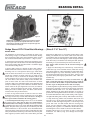
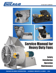
Service Manual for
Heavy Duty Fans
Safety
Installation
Operation
Maintenance
CHICAGO BLOWER CORPORATION • GLENDALE HEIGHTS, ILLINOIS • USA
CONTENTS
INTRODUCTION. . . . . . . . . . . . . . . . . . . . . . . . . . . . . . . . . 1
INSTALLATION . . . . . . . . . . . . . . . . . . . . . . . . . . . . . . . . . . 2
Unloading and Handling. . . . . . . . . . . . . . . . . . . . . . . . . . 2
Foundations. . . . . . . . . . . . . . . . . . . . . . . . . . . . . . . . . . . . 2
Duct Location and Design. . . . . . . . . . . . . . . . . . . . . . . . 3
Fan Erection. . . . . . . . . . . . . . . . . . . . . . . . . . . . . . . . . . . . 4
Housing Alignment . . . . . . . . . . . . . . . . . . . . . . . . . . . . 4
Pedestal Alignment . . . . . . . . . . . . . . . . . . . . . . . . . . . . 5
Rotor Assembly . . . . . . . . . . . . . . . . . . . . . . . . . . . . . . . 5
Inlet Cone/Inlet Volume Control . . . . . . . . . . . . . . . . . 5
Bearing Assembly and Alignment . . . . . . . . . . . . . . . 6
Flexible Couplings . . . . . . . . . . . . . . . . . . . . . . . . . . . . 7
V-Belt Drive . . . . . . . . . . . . . . . . . . . . . . . . . . . . . . . . . . 9
ACCESSORY INSTALLATION. . . . . . . . . . . . . . . . . . . . 10
OPERATION. . . . . . . . . . . . . . . . . . . . . . . . . . . . . . . . . . . . 11
Vibration Limits . . . . . . . . . . . . . . . . . . . . . . . . . . . . . . . . 12
MAINTENANCE. . . . . . . . . . . . . . . . . . . . . . . . . . . . . . . . . 13
TROUBLE-SHOOTING GUIDE. . . . . . . . . . . . . . . . . . . . 14
BEARING DETAIL. . . . . . . . . . . . . . . . . . . . . . . . . . . . . . . 16
Dodge Sleevoil PLXC Bearings. . . . . . . . . . . . . . . . . . 16
Dodge Sleevoil RTL Bearings. . . . . . . . . . . . . . . . . . . . 18
Bearing Tables. . . . . . . . . . . . . . . . . . . . . . . . . . . . . . . . . 19
Solid Pillow-Block Bearings. . . . . . . . . . . . . . . . . . . . . . 20
Split Pillow-Block Bearings. . . . . . . . . . . . . . . . . . . . . . 22
RECORD of FAN INSTALLATION. . . . . . . . . . . . . . . . . 25
WARRANTY. . . . . . . . . . . . . . . . . . . . . . . . . . . . . . . . . . . . 25
Air Movement and Control Association International
30 West University Drive
Arlington Heights, Illinois 60004
www.amca.org
HDM-2153 REV. 2008
INTRODUCTION
a fan under high temperature or in an extremely corrosive
atmosphere.
GENERAL INFORMATION
This manual is intended to aid in proper installation and operation of Heavy Duty fans manufactured by Chicago Blower Corporation (CBC). Due to the wide variety of arrangements and types
of Heavy Duty fans, it is not intended to cover detailed installation procedures. Each purchaser of a Chicago Blower Heavy Duty
fan is furnished with a detailed assembly drawing showing working conditions and a bill of material which is the Parts List. Any
special features or installation requirements are described on this
drawing to aid in proper installation and start-up. An operating
performance curve is available through the CBC sales office which
sold the equipment. A convenient Record of Fan installation is
located on the inside back cover of this manual.
The housing access doors must not be opened when the fan is
in operation. Those on the discharge side of the fan can explode
when unbolted.
Proper protection from electrical start of the fan during maintenance is required. A disconnect switch provided with a padlock
to prevent operation of the fan is required. In addition,
a disconnect switch should be located at the fan for use by
personnel working on the fan.
RECEIVING and INSPECTION
Chicago Blower Corporation equipment is thoroughly inspected
prior to shipment and, barring damage in transit, should be in
good condition. All shipments must be carefully inspected by the
Receiving Agent for damage. When a carrier signs Chicago
Blower Corporation’s bill of lading, the carrier accepts the
responsibility for any subsequent shortages or damage; and any
claim must be made against the carrier by the purchaser. Evident
shortage or damage should be noted on the carrier’s delivery
document before signature of acceptance. Inspection by the carrier of damage, evident or concealed, must be requested. After
inspection, contact the Chicago Blower Service Manager. A purchase order will be required for any part shortages. In the event
of damage, a return materials authorization number will be
assigned for the return of the equipment with Freight Prepaid.
Damage assessment, and a repair price quotation will be provided once these parts have been received at Chicago Blower.
It is the responsibility of the purchaser to insure that installation
and operation is handled by qualified personnel experienced in
this type of equipment. Omission in this manual or on CBC assembly drawings of details, or operation methods commonly considered good practice by competent erection personnel, are not the
responsibility of Chicago Blower Corporation.
A staff of trained field service and erection personnel is available
from CBC to supervise installation or check alignment and
balance at startup. Contact the Service Manager at CBC or your
local CBC representative to arrange for this service.
SAFETY PRECAUTIONS
The fan you have purchased is a rotating piece of equipment that
can become a source of danger to life, and can cause injury if not
properly applied. Maximum operating temperature and speed
for which this fan is designed must not be exceeded. These
limits are given in our catalog, or in the order acknowledgement,
or on Chicago Blower Corporation drawings.
STORAGE PRECAUTIONS
If storage of equipment is necessary prior to erection, precautions must be taken to prevent damage. The rust preventative
paint applied to the fan housing is sufficient in most environments. The rust preventative compound applied to machined
surfaces by CBC, such as shafting, bearing pedestals and sole
plates, is intended for in-transit protection only. If prolonged outside storage is necessary (more than two weeks), additional
applications of rust preventative compounds, waterproof paper,
tarpaulin or plastic covers are the responsibility of the purchaser.
Covered equipment must be provided with moisture absorption
material.
Personnel who will operate this fan, or those who will perform
maintenance thereon, must be given a copy of this manual to
read, and be warned of the potential hazards of this equipment.
This manual contains general recommendations, but attention
must also be paid to the specific safety requirements which apply
to the individual installation. Such requirements are outlined in
federal, state and local safety codes. Strict compliance with these
codes, as well as strict adherence to installation instructions, are
the responsibility of the user and are necessary to the safe operation of this fan.
Motors, pedestals, dampers, shafts and bearings should be stored
in a temperature controlled building to prevent deterioration
prior to erection. Bearings received not mounted to the shaft
should be stored in the original package and tightly sealed to
prevent corrosion or buildup of foreign material during storage.
In most cases, standard preparation for shipment by bearing,
coupling and motor manufacturers is not sufficient for prolonged
outdoor storage. If fan is provided with mounted grease lubricated bearings, lubricate the bearings with a premium quality
NLGI2, lithium soap base, mineral oil grease upon receipt of fan.
Add enough grease to cause a slight purge at the seals while
rotating the shaft. This procedure must be done twice every
month thereafter until the fan is placed in service.
The elements which connect the driving mechanism to the fan
(V-belt drives or couplings) create potential DANGER to
personnel and suitable guards must be provided.
Bearing assemblies and drive couplings must be covered so
that no rotating element can snag clothing or skin. Shaft cooling wheels or any other rotating part must be covered. Any open
sheave, pulley, sprocket, belt, chain, and other similar transmission device must be enclosed by guards.
Another potential hazard is the ability of the fan to convey loose
material which can be a projectile. Ducts must be protected
to prevent objects from entering the airstream. Place suitable
guards over inlets and outlets of fans to prevent the
entrance of clothing or flesh into the rotating parts.
If a rotor (wheel and shaft) is received as a separate assembly,
block each end of the shaft to prevent sagging. When a wheel is
located in a fan housing, the wheel must be rotated ten full
revolutions approximately once every two weeks.
Vibration limiting switches should be provided to detect sudden
changes in the operation of the fan, especially when operating
1
INSTALLATION
driver. This mass acts as an inertia block and will absorb any
normal vibration that might develop, as well as hold the driver
and fan in perfect alignment. It is preferred that the bottom of
the base be larger than the top, with the degree of taper to the
footing course dependent on the available sub-foundation. The
edges of the foundation should be beveled to prevent chipping
and should extend at least 6" beyond the fan structure. A minimum allowance of 1" should be made for shimming and grouting
when the top level of the foundation is determined. (See Figure 2)
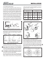
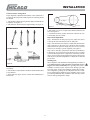
UNLOADING and HANDLING
Chicago Blower fans must be handled and moved using
good rigging techniques, being careful to avoid concentrated stresses that distort any of the parts.
Rotor Assembly:
Many CBC Heavy Duty wheels are furnished as a rotor assembly
complete with a shaft, and often with a shrink fit between wheel
and shaft. This rotor assembly may be shipped on a fabricated
steel cradle for ease of handling in shipment and unloading.
Remove the rotor assembly from the cradle by placing slings
around the shaft as close as possible to either side of the wheel.
A spreader bar on the hoisting cables must be used to prevent
damage to the wheel during lifting (See Figure 1). Do not use any
part of the wheel rim for lifting purposes. Do not put the sling on
portion of the shaft where the bearings will later be mounted.
Rotors must never be lifted by the wheel, blades or sideplates, or
allowed to rest on the ground without blocking the shaft ends.
Wheels should never be rolled if lifting equipment is available. If
rolling becomes necessary, extreme caution must be exercised
to prevent damage. A wheel that has been knocked out of round
must be rebalanced.
Steel shims must be
placed at all anchor
bolts, all four corners,
and at intermediate
points if any deflection
is determined visually.
Notch shims for corner
anchor bolts if required
Plan View
SPREADER BAR
Shims must extend
beyond base angles
Figure 2
Figure 1
LIFT HERE
Elevation View
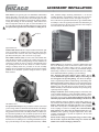
Sole plates under the bearing pedestals and motor base plate,
(See Figure 7, Page 5), are recommended for use on concrete
foundations. Parts can then be removed without disturbing the
cement or grout, making realignment easier.
LIFT HERE
If the wheel is separate from the shaft, a wrapped sling or timber
may be passed through the hub for lifting. Extreme care must be
taken not to damage the finished bore of the hub, or the bearing
and hub surfaces of the shaft.
“J” shaped hold down bolts should be used in the concrete (See
Figure 3). They should be placed in a metal sleeve or pipe with a
diameter 2-1/2 times the hold-down bolt diameter to allow
minor adjustment after the concrete has cured. When determining the length of anchor bolts, allow 1" extra length for leveling
and grout, flange thickness of the fan foundation, nut, washer,
and extra threads for draw down. “J” bolts must be positioned so
the bottom does not break out of the concrete.
Housing:
In unloading and handling large housing sections, an attempt
should be made to lift from as many points as possible. Spreader
bars must be used to prevent concentrated stresses that can
collapse the housing and cause permanent distortion. Inlet box
and outlet dampers must be handled with care, as distortion
could cause binding during operation.
Fans covered with special coating or paint must be protected in
handling to prevent damage. Avoid nicks or cuts in the coating
which may be difficult and expensive to repair.
BOLT
STEEL PIPE
FOUNDATIONS
A rigid, level foundation is a must for every fan. It assures
permanent alignment of fan and driving equipment, reduces
excess vibration, and minimizes maintenance costs. The
sub-foundation (soil, stone, rock, etc) should be firm enough to
prevent uneven settlement of the structure. Foundation bolt
locations are found on the assembly drawings.
Figure 3
WASHER
WELDED TO BOLT
Structural Steel Foundations:
If the fan is mounted on equipment having parts which cause
vibration, it is very important that fan support be rigid enough
to prevent such vibration from being carried to the fan. The
resonance frequency of this support must be a minimum of 25%
above the maximum fan speed.
Poured Concrete:
Reinforced pored concrete is the preferred foundation for Heavy
Duty fans. The minimum design weight of a concrete foundation
should be three times the total assembly weight of the fan and
2
INSTALLATION
When a structural steel foundation is necessary, it must be sufficiently rigid to assure permanent alignment. It must be designed
to carry, with minimum deflection, the weight of the equipment
plus the loads imposed by centrifugal forces set up by the rotating element. In such cases, the design of the structure must
permit field revisions (such as knee braces) if initial operation
indicates a need for increased stiffness.
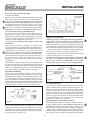
OUTLET CONNECTIONS
RIGHT
DUCT LOCATION and DESIGN
When locating the foundation, carefully plan the ducting or
breaching to the fan to avoid possible air performance problems.
To deliver stable rated performance, fans require smooth, straight
distributed flow into the inlet and straight flow out of the outlet for
a distance of at least three duct diameters. Where duct turns or
abrupt change in duct dimensions are necessary within three duct
diameters of fan outlet, flow distributing devices (turning vanes)
must be installed (See Figures 4 and 5). Where these means are
impractical, such as close to the fan outlet, the amount of fan performance loss can be found in AMCA Publication 201 (see front
cover for address). Care must be taken to prevent spiral or vortex
flow into fan outlet since these flow conditions frequently cause
pulsation or unstable delivery. Contact your local Chicago Blower
sales office for further information. (See back cover)
WRONG
RIGHT
TURNING
VANES
RIGHT
WRONG
RIGHT
WRONG
RIGHT
WRONG
Duct Connections:
vid
ded
d
Flexible connections and/or expansion joints must be prov
at fan inlet and outlet to isolate the fan from duct static loads,
duct temperature expansion loads and from vibration loads. Flexible connections may be multiple bellows expansion joints,
banded slip joints, or fabric or sheet plastic flexible joints. Flexible connections may require acoustic treatment to reduce noise
radiation. Ducts must be separately anchored near the fan.
INLET CONNECTIONS
WRONG
RIGHT
RIGHT
RIGHT
RIGHT
WRONG
TURNING
VANES
RIGHT
Figure 4
RIGHT
WRONG
RIGHT
WRONG
Figure 5
3
RIGHT
RIGHT
WRONG
WRONG
INSTALLATION
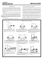
Set and Align Housing on Foundation:
FAN ERECTION
Erection as covered in this section, specifically covers Arrangement 3-SISW and 3-DIDW fans with independent pedestals.
Although the procedure for installing A/1, A/4, A-7 and A/8 fans
differs slightly, they are generally less complicated to install and
incorporate simple modifications of some of the steps outlined.
See Figure 6.
If the housing was shipped knocked down, the bottom half must
be lifted onto the foundation first. Place wooden blocks beside
the anchor bolts to prevent damage to them while the housing is
being moved into proper position. The housing should be lifted
from as many points as possible. The use of spreader bars will
help minimize distortion. When the housing is properly aligned
over the anchor bolts, it should be lifted up one side at a time, the
block removed, and the housing lowered carefully onto the foundation. Permanent shims approximately the same size as the
grout should be placed on either side of each anchor bolt. The
shims should extend beyond the edge of the base angle and
should be approximately 4" wide. These shims will give the
housing good support and prevent it from slipping when the
anchor bolts are drawn down. See Figure 2, Page 2.
For Arrangement 1, 7 and 8 fans, level shaft between bearings.
Shim under base to attain level. Tighten foundation hold-down
bolts. Some fans with disjointed bases are shipped from the factory with “shipping clips” (bars holding the fan housing and
pedestal together). DO NOT REMOVE THESE CLIPS UNTIL
GROUTING IS COMPLETE. Always remove these clips before
operating the fan.
For fans with independent pedestals, proceed as follows:
DRIVE ARRANGEMENTS FOR CENTRIFUGAL FANS
ARR. 1 SISW With Inlet Box For belt drive
or direct connection. Impeller overhung, two
bearings on base. Inlet box may be self-supporting.
ARR. 3 DIDW With Independent Pedestal
For belt drive or direct connection. Housing is
self supporting. One bearing on each side
supported by independent pedestals.
ARR. 7 SISW With Inlet Box For direct
connection. Arrangement 3 plus base for
prime mover.
Figure 6
SISW – Single Inlet, Single Width
DIDW – Double Inlet, Double Width
ARR. 3 SISW With Independent Pedestal
For belt drive or direct connection. Housing is
self supporting. One bearing on each side
supported by independent pedestals.
ARR. 3 SISW With Inlet Box and Independent
Pedestals For belt drive or direct connection.
Housing is self supporting. One bearing on each
side supported by independent pedestals with
shaft extending through inlet box.
ARR. 3 DIDW With Inlet Box and Independent Pedestals For belt drive or direct connection. Housing is self supporting. One bearing on
each side supported by independent pedestals
with shaft extending through inlet box.
ARR. 8 SISW With Inlet Box For direct
connection. Impeller overhung, two bearings
on base plus extended base for prime mover.
Inlet box may be is self supporting.
4
ARR. 4 SISW For direct drive. Impeller
overhung on prime mover shaft. No bearings on fan. Prime mover base mounted or
integrally connected.
ARR. 9 SISW For belt drive. Impeller
overhung, two bearings, with prime mover
outside base.
INSTALLATION
or shaft seal. Set keys in position and tighten set screws just
enough to hold wheel on shaft during handling. Tighten fully when
clearances have been set. See Table I.
Set and Align Bearing Pedestals:
The bearing soleplates and pedestal assembly should be put in
place, using shims to approximately the bearing centerline height
as shown on the fan assembly drawing. The fixed bearing must
be leveled at this time using flat shims under the sole plate.
Approximately 1/8" should be allowed for shimming between
pedestal top and bearing for possible future alignment problems
caused by settling of the foundation. In leveling the sole plate,
adjusting nuts on the “J” bolts are helpful but after final alignment, hard shims must be placed next to each “J” bolt and under
the center of the sole plate before grouting. See Figure 7. Note the
pedestal can be removed from the side without disturbing foundation bolts. Use the same procedure to align the floating bearing.
Table I
Wheel Set Screws
Square Head
Socket Size
1/4"
5/16"
3/8"
7/16"
1/2"
5/8"
3/4"
7/8"
1"
On top of the pedestal, shims running the full length and half the
width of the bearing foot, slotted to fit around the foundation
bolts, provide the most solid mounting arrangement for later
mounting the bearings. Temporarily bolt down bearing pedestals.
Wheel Set Screws
Allen Head
Torque in/lbs
66
136
239
384
586
1163
2076
1992
3000
Socket Size
1/8"
5/32"
3/16"
7/32"
1/4"
5/16"
3/8"
7/16"
1/2"
Torque in/lbs
66
136
239
384
586
1163
2076
1992
3000
On a rotor with a factory shrink fit, the preparation of the rotor
assembly is limited to cleaning the shaft for installation.
CLEARANCE FOR
FOUNDATION BOLT WHEN
REMOVING PEDESTAL
Figure 9
PEDESTAL
SOLE PLATE
HARD SHIM
HARD SHIM
3/4" MIN.
GROUTING
J-BOLT
Figure 7
Section view showing pedestal, sole plate and grouting.
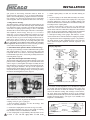
Prepare Rotor Assembly:
All Chicago Blower Corporation Heavy Duty wheels are shipped
with a shrink fit or slip fit to the shaft. Check for proper wheel
rotation with the rotation arrow on the drawings, on the fan, or
the diagrams in Figure 8.
ROTATION
ROTATION
ROTATION
Radial Tip
Design 4800, 4806, 4896,
5000, 5400 , 1807
Radial Blade
Design 2000,
4900, 2300
Airfoil/Backward Curved
Design 1900, 1910A, 1911,
5500, 5800, 6100
ROTATION
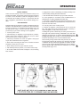
Set Inlet Cone, Ring, or Inlet Volume Control
Figure 8
At this time, the Inlet Cone and retaining rings (or Inlet Volume
Controls, if furnished) are placed over the shaft end for mounting
the rotor assembly in the housing. See Figure 9. If inlet volume
controls are provided, check for proper rotation. See Figure 10.
Inlet vanes in the half closed position must pre-spin the air in the
direction of wheel rotation. On a DIDW fan, one inlet vane control is clockwise and the other counter-clockwise. Do not install
them reversed. Secure inlet vane controls to wheel for lifting
purposes. Do not allow vane center mechanism to rest on shaft
as damage will result.
Backward Inclined
Design 1910B
Direction of Rotation for Various Blade Shapes
(shown for counterclockwise from drive side)
For wheels shipped separate from shafts:
Carefully place the wheel on the floor and brace in position.
Remove any protective coating from the shaft and hub. Check for
rust, corrosion and nicks. If cleanup is necessary, DO NOT USE
EMERY CLOTH on any bearing surface. Crocus cloth may be
used if necessary. Clean the shaft portion that fits into the wheel,
as well as the wheel bore itself. Remove all keys and loosen set
screws. Check fan assembly drawing for location of wheel on
shaft. Rotation is as viewed from the non-inlet side. On dual
drive or double inlet units, it is generally from the “fixed” bearing end. Refer to general assembly drawing.
OPEN
On a wheel and shaft with a clearance fit, lift shaft using padded
slings. Carefully slide end into wheel hub and push through until
wheel is properly located on shaft as shown on the assembly
drawing. Extreme care must be taken not to damage wheel bore
Figure 10
5
CLOSED
OPEN
9 BLADE
CLOSED
7 BLADE
INSTALLATION
Prepare Bearings, Set Rotor Assembly:
Figure 11B
1. For Sleeve Bearings:
WHEEL TO CONE
DIMENSION
Remove bearing caps and clean bearing housings and liners with
solvent. Coat with clean oil and cover to avoid contamination.
Clean oil rings and shaft seals. Do not mix parts between the
bearings as they are not interchangeable. Bolt the lower half of
the bearing housings loosely in place. Again cover to prevent
contamination. Sling the rotor assembly as previously described.
Lower the rotor assembly into the bearing housing. For further
information refer to Sleeve Bearing Detail Section, Page 16.
a
Wheel to cone fit. Clearance (a) should be uniform all
around inlet cone at fan installation for ambient air fans.
See fan assembly drawing for clearance on ID or hot fans.
2. For Anti-friction Bearings–Solid Pillow Blocks:
Non-split pillow blocks are slipped over the shaft ends prior to
putting the rotor in place. Check to insure that the floating
bearing (unless specified on the assembly drawing) is on the side
opposite the driver. See Figure 12. Bolt bearings loosely on the
pedestals. For further information, see Page 20.
Adjustments for Expansion
Induced Draft Fans, or other high temperature applications,
require wheel and cone adjustments for expansion due to
temperature. This is because the housing expands up from the
foundation while the rotor expands concentrically from the shaft
centerline as well as axially from the fixed bearing. The following
rules of thumb should be used on applications in excess of 300°F.
3. For Anti-friction (Roller) Bearings–Adapter Mount, Split
Pillow Blocks:
Cleaning of the internal parts should not be required as the
corrosion preventative compound applied by the manufacturer is
compatible with recommended lubricants. Careful inspection of
all internal parts is good practice, as any corrosion present is
likely to cause problems at a later date. Do not mix housing
parts between bearings as they may not be interchangeable.
1. Axial over lap on double width fans should be approximately
twice as much on the drive side as on the floating side.
2. Radial clearance between the wheel and inlet cone(s) should
be twice as much at the top as at the bottom.
The bottom half of the pillow block is loosely bolted in place on
the pedestals. Pillow blocks and bearing parts exposed to
atmosphere must be covered with a clean cloth to prevent
contamination.
For induced draft fans or other high temperature applications
over 300° F., care should be taken to duplicate exactly the
wheel to cone clearances recommended on the assembly
drawing. Cold settings are shown on the assembly drawing.
The internal parts of the bearing are placed on the shaft ends in
the same order that they were removed from the pillow block.
See Figure 13. Sling the rotor assembly as described previously and
lift into place. Put bearing caps in place to prevent contamination
prior to final alignment. For further information, see Page 22.
FIXED
BEARING
Align Rotor and Housing
FIXED
BEARING
DIRECTION OF
DRIVER
As a first step to proper alignment, level the drive side bearing.
The floating bearing will later be shimmed to account for the
shaft deflection. See Figure 11A. In leveling the bearing, see that
the shaft centerline is the proper height for connection to the
driver. After shimming of the drive bearing is complete, it should
be drawn down. The floating bearing should be shimmed to take
up the shaft deflection and should be drawn down in conjunction
with the alignment of the inlet cone or inlet volume control.
COUPLING
FLOAT
BEARING
WHEEL
DRIVER
DIRECTION OF
EXPANSION
Figure 12
Set and Align Bearings
Setting of the drive side bearing level with the driver and aligning the outboard bearing have been mentioned previously. It is
preferable that the drive bearing be set level to facilitate alignment of the driver, which is also set level. Any shaft deflection
caused by suspension of the rotor weight between the bearings
must be accounted for in the outboard bearing by placing shims
under it. See Figure 11A. Shaft level is placed on the shaft at the
journals and compared to the machined surface of the bearing
housing until an equal slope is achieved.
FLOAT
BEARING
LEVEL
LEVEL
LEVEL
LEVEL
LEVEL
EXPANSION
COUPLING
SHIM UP
LEVEL
Align Inlet Cones or Inlet Volume Controls
Figure 11A
After the alignment of the rotor assembly, coupling and drive is
complete, the inlet cones or IVCs should be repositioned to
provide proper clearance. Center the cones on the inlet eye of
the wheel. At this time the IVC linkage should be assembled as
required. Details of linkage arrangement are supplied on the fan
assembly drawing. Install gasketing in housing split. Apply caulking on the lower side to hold the gasket material. Then install the
Wheel to cone alignment details are included on the assembly
drawing provided with each fan. The drawing gives a dimension
for the inlet cone to wheel backplate distance. Check this alignment before final tightening of pedestals, bearing bolts and bearing locking devices. See Figure 11B
6
INSTALLATION
5. Install coupling hub(s) on shaft. See customer drawing for
position.
split portion of the housing. Allowance must be made for
expansion when operation is to be at elevated temperature.
(Refer to the assembly drawing.) Tighten all fasteners in foundation, pedestals, etc. that were previously left loose. Install shaft
seals if supplied. Turn rotor by hand to make sure it runs freely.
6. Key the couplings to the shafts while the hub(s) are still hot.
7. Adjust the clearance between the coupling faces. The proper
clearance dimension is listed on the assembly drawings and
included in manufacturer’s information. This dimension may also
be stamped on the coupling hubs.
1. Dodge Sleeve Bearings
The elliptical shape of sleeve bearing liners makes lining up the
bearings square with the shaft relatively simple. When the shaft
rests in the liners, there is clearance on both sides the full length
of the liners. In squaring up the bearings, a .0015 or .002 shim
should be able to run the entire length of the liner at a fixed depth.
8. When a sleeve bearing is used, locate it so that when the
motor rotor is closest to the fan, the motor shaft will not touch
the fan shaft. If the motor shaft has its magnetic center marked,
align it in this position. Otherwise equally divide the maximum
play to obtain the mechanical center. Align in this position
After alignment, install oil rings. Sizes up to 3-7/16" have a
single ring; 3-15/16" and up, double rings. Tighten set screws
on the rings and be sure that the rings rotate freely on the shaft.
Run dust seal into its groove in the housing and fasten ends together. Next, apply a coating of oil on the upper portion of the
liner and put in place. Place cap on bearing and tighten stud
nuts. The plunger screw must be loose before the stud nuts
are tightened. Detail instructions on sleeve bearing assembly
can be found in the Bearing Detail Section, Page 16.
9. With tapered wedge, feeler gauges, dial indicator, or laser,
observe that the faces of the fan and driver couplings are parallel.
10. Align the shafts until a straightedge appears to be parallel to
the shafts. Repeat at three additional points at 90° from each
other. Recheck angular alignment and hub separation. (See
Figure 14)
Coupling Alignment
2. Solid Pillow Block Spherical Roller and Ball Bearings
Rubber Bushed or Pin Type
Slide, tap or press bearings on shaft. Establish final shaft position
and tighten bearing to support. Position locking collar and
torque CBL Grade 2 set screws to the bearing manufacturer’s
recommended torque values. See bearing assembly instructions
in Bearing Detail, Page 20.
Disc Type
Straight
Edge
3. Split Pillow Block Spherical Roller Bearings
Grid Type Coupling
The lower half of the pillow block should be bolted loosely to the
pedestal. After assembling bearing parts on the shaft in the same
order as Figure 13, hand tighten the adapter assembly. Be sure
that the bearing is properly positioned on the shaft before tightening to the proper clearances. The space in the expansion or
floating bearing should always be on the outboard side or side
away from the drive (coupling) bearing. See bearing assembly
instructions in Bearing Detail section, Page 22.
1
Gear Type Coupling
Straight
Edge
4
3
2
Check all types at four positions 90° apart as shown
Figure 14
11. For more accurate alignment, use a dial indicator clamped
on one hub, with the dial indicator button resting on the other
hub. Rotate the hub on which the indicator is clamped, and
observe the indicator reading. Take readings at four locations,
90° apart. With correct alignment, the faces of the couplings
should be parallel within .001 per inch of shaft diameter, in both
parallel and angular planes. (See Figure 15) If available, laser
alignment is recommended.
Figure 13
Flexible Coupling Installation and Alignment
These instructions cover, in general, the installation of flexible
couplings of the pin, gear, or grid types.
Dial Indicator
1. Before mounting coupling(s), be sure all bearings, inlet
vane(s), etc. have been installed.
Radius
Index Line
2. Install each coupling half-cover with “O” ring on its shaft.
3. Determine which direction, long or short, shank of coupling
hub should be located. See manufacturer’s manual.
Rubber For
Gap Spacing
Parallel Alignment
4. Heat coupling hub to approximately 300°F by means of hot
oil bath or oven. Do not apply flame to hub teeth.
Figure 15
7
Angular Alignment
INSTALLATION
12. Where large turbines or motors are used as drivers, the driver
side of the coupling should be set low by a few thousandths to
allow for the driver to heat up during operation when it will
expand and bring the coupling into alignment. A rule of thumb for
initial alignment of a large motor is: Set driver low .001" for each
1" of shaft diameter; i.e 1" shaft motor low by .001", 2" shaft
motor low by .002. Set turbines low by .001" per inch of turbine
height from mounting feet to centerline of shaft. After unit has
operated and thermal expansion is complete, coupling alignment
should be checked and corrected if necessary.
SPECIAL NOTE ON ALIGNMENT:
On any completely assembled fan, where CBC has mounted the
motor and coupling, it is required that the alignment be
rechecked after the fan is set on its permanent foundation. It is
not possible to hold alignment during shipment or when set on a
different foundation. Alignment must be within specifications and
the coupling lubricated. A tag is attached to the coupling guard
warning installer of re-alignment requirement.
13. After completing the coupling alignment, clean both sides of
the coupling thoroughly, and inspect the gasket for tears, cracks
or other damage.
NOTICE
This coupling was carefully aligned at the factory
before shipment. Due to variations in foundations
THIS COUPLING MUST BE REALIGNED after fan
is finally “set”. See Coupling Mounting Instructions
enclosed in Packing List envelope.
14. Install the gasket between the coupling halves. Draw the coupling flanges together keeping gasket holes in line with bolt
holes. Insert and tighten bolts, lockwashers and nuts.
15. Lubricants formulated for couplings are available from the
specific coupling manufacturer; ie Falk’s LTG (Long Term Grease)
or Kopflex’s KSG or KHP. Both are NLGI Grade #1/#2 Grease.
If unavailable lubricate in accordance with type of operating
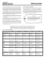
conditions shown in Table II.
The lubricants listed below are recommended by the lubricant manufacturers for the
indicated conditions. This list is solely for our customers’ convenience and does not
constitute an endorsement. This listing is not intended to be complete nor necessarily
current due to continuous research and improvement by the various manufacturers.
Table II – COUPLING LUBRICANTS
LUBRICANT
MANUFACTURER
GENERAL
MOIST OR WET
HIGH TORQUE
150°-300°F
CLASS lll
American Lubricants
Atlantic Richfield
Amoco
Alubco Bison 1650
Arco MP
Amolith #2
(same)
Arco MP
Amolith #2
(same)
Arco EP or Moly D
Amolith #2
(same)
Dominion H2
Rykon EP-2
(same)
Dominion H3
Amoco CPLG Grease
Chevron USA.
Cities Service
Duralith EP-2
Citgo AP or HEP-2
––––
Duralith EP-2
Citgo AP or HEP-2
––––
Duralith EP-2
Citgo AP or HEP-2
––––
Duralith EP-2
Citgo AP or HEP-2
––––
NL Gear Compound
460 Citgo AP or EP
Compound 130
Continental .
Far Best
Super Sta Grease
––––
Molyvis ST-200
HD Calcium Grease
––––
(same)
HD Calcium
––––
(same)
HD Calcium
––––
(same)
HD Calcium, Transmission Oil No. 140
None
Fiske Bros. Refining
Gulf Oil
Exxon
Lubriplate 630-AA
Gulfcrown EP #2
Pen-O-Lead EP 350
Lubriplate 630-AA
Gulfcrown EP #2
Rolubricant EP 300
Lubriplate 630-AA
Gulfcrown EP #2
Rolubricant EP 350
Lubriplate 1200-2
Hi-Temp Grease
Unirex N2
Lubriplate No. 8
Precision No. 3
Unirex N2 or Nuto 146
Kendall Refining
Kenlube L-421 or
Waverly Torque Lube A
Mobilux EP-O
L-421 or Torque Lube A
––––
Mobilux EP-O
L-421 or Torque Lube A
––––
Mobilux Temp 78
L-421 or Torque Lube A
––––
Mobilux Temp 78
L-421 or Torque Lube A
––––
Mobilux No. 28
Pennzoil
Pennlith 711 or 712
––––
Pennlith 711 or 712
––––
Pennlith 711 or 712
––––
Pennlith 712 or Bearing
Lube 706
Hi Speed Pennlith 712
or Bearing Lube 706
Suntech
Sunaplex 991 EP or
Prestige 741 EP
(same)
(same)
(same)
Syn-Tech
Tenneco Chemicals
Texaco
Union Oil Co. of Calif.
3913-G1
Anderol 786
Multifak EP-2
UNOBA EP-2
(same)
(same)
Multifak EP-2
UNOBA EP-2
(same)
(same)
Multifak EP-2
UNOBA EP-2
(same)
(same)
Thermatex EP-2
UNOBA EP-2
Mobil Oil
For low temperatures (-65°F), Aeroshell #22 by Shell Oil Co., Anderol 793 by Tenneco Chemicals, Inc., and Mobil Grease #28 by Mobil Oil Co.
8
–––––
(same)
(same)
Thermatex EP-2
MP Gear Lube 140
INSTALLATION
V-Belt Fan Drive Arrangement
Proper alignment, adjustment and balance of the V-Belt drive is
essential to smooth operation and long life. The following should
be checked:
Too Tight
1. Fan and motor shafts must be parallel. Adjust and shim motor
as required. See Figure 16.
Slight Bow
2. Fan and motor sheaves must be aligned axially. See Figure 16.
Figure 17
Too Loose
Fan Belt Alignment
6. Belts either too loose or too tight cause vibration and excessive
wear. See Figure 17.
7. For field erected fans, position the sheaves and belts as close
to the bearing base as possible.
Belt Tension Adjustment
Step 1: With all belts in their proper grooves, adjust the centers
to take up all slack and until the belts are fairly taut.
Step 2: Start the drive and continue to adjust until the belts have
only a slight bow on the slack side of the drive while operating
under load. If belts squeal at startup, they are too loose. Correct
tension is just enough to prevent squealing. See Figure 17.
Fan Belt Tension
Step 3 After a few days operation the belts will seat themselves
in the sheave grooves and it may become necessary to readjust
so that the drive again shows a slight “bow” in the slack side. The
drive is now properly tensioned and should operate satisfactorily
with only an occasional readjustment to compensate for belt and
groove wear.
Cord Tied
To Shaft
Cord Touching Sheaves At Points
Indicated By Arrows
Grouting Unit
After completion of all installation and alignment procedures, it
is recommended that a Chicago Blower Corporation Service
Engineer check the installation prior to grouting. This service is
available on a daily fee plus expenses basis through your CBC
local sales office or the Service Manager at CBC. After verification of alignment, grouting can be completed. There are a number of commercial non-shrinking grouts available, such as 5 Star
grout having aluminum chips or Embaco with steel chips. Allow
72 hours after grouting before startup.
Figure 16
3. Adjustable motor sheave grooves must have no noticeable
eccentricity.
4. Fan and motor sheave balance should be checked when there
is any vibration.
5. Belts must have proper tension. Follow drive manufacturer’s
instructions.
9
ACCESSORY INSTALLATION
Shaft Coolers are typically split cast aluminum radial bladed
wheels designed to dissipate heat conducting down the shaft
toward the bearings. The two halves are bolted together around
the fan shaft with the backplate toward the fan housing and the
cooling fins drawing air over the bearings. Some shaft coolers
have a straight bore and are not split. Set screws hold these coolers to the shaft. Consult the assembly drawing for proper location.
An expanded metal guard must be installed over cooling wheels.
units, detailed linkage mounting information is on the fan
assembly drawings. At installation, make sure they prespin the
air in the direction of wheel rotation. See Figure 18, Page 11.
Note: Some fans are provided with fresh air, opposed bladed inlet
box dampers. These are typically used when recirculated flue gas
is introduced back into the fan’s inlet airstream. These dampers
are located above the FGR connection.
Backplate
Cooling Fin
Typical Shaft Cooler
Standard CBC Shaft Seals are compressed fibrous material. Split
seals are furnished as standard on most fans, both on the inlet
box and drive sides of the fan. This seal is clamped in place by a
split metal retainer plate. These seals are not gas tight.
Inlet Volume Controls (IVC) are inlet cones with variable inlet
vanes mounted in them to regulate fan volume and power. On
double inlet units, interconnecting linkage assures simultaneous
operation. See Figure 10, Page 5 on how to check that the vanes
are spinning the inlet air in the direction of wheel rotation.
Linkage assembly details are provided on the fan assembly
drawing. IVCs are furnished for manual operation with a locking
quadrant or for automatic operation using an electric or pneumatic actuator.
Outlet Damper
Prespin Inlet Damper
Outlet Dampers are mounted in a separate channel frame and
bolt to the discharge outlet of the fan for volume control. The
damper blades are double surface and are opposed blade.
Dampers operating in excess of 200°F are provided with flanged
ball bearings mounted on stand-off channel and cast stuffing
boxes with braided fibrous packing to prevent leakage.
Note: On high temperature dampers (above 300°F), the set
screws should not be tightened in the damper axle bearings on
the side opposite the operating linkage. This allows the damper
shaft to expand away from the locked bearings on the linkage side.
Damper Inspection. Whether damper is received installed on the
fan or shipped separately, check all the levers, linkage and blade
hardware to be sure that they are secure. Operate the control
handle manually to check that all the blades are operating freely,
open fully and close tightly.
Damper Installation. When installing dampers in the field, refer
to the assembly drawing to assure that damper linkage is in the
proper position and the blades rotate from closed to open position in the correct rotation. Desired fan performance may not be
obtained if proper blade rotation shown on drawing is not observed.
Double width fans using two dampers operate with a single control arm and a shaft connecting the two dampers. Blades in both
dampers must fully open and close together. The connecting
shaft often is in two pieces, and although a set screw is provided
in the coupling as an aid for assembly, this section should be
field welded to the shaft after the damper blades are synchronized. Fans operating at higher temperatures have shaft
coupling arrangements to provide for expansion. Do not weld
both ends to the shaft.
Inlet Volume Control
Prespin Inlet Box Dampers are provided for volume control and
power savings similar to that achieved with the IVC. The damper
comes in a separate channel steel frame with damper axles running parallel to the fan shaft. The damper blades are double surface and when partially closed, the blades prespin the air in the
direction of wheel rotation. Units operating in excess of 200°F
are provided with flanged ball bearings mounted on stand-off
channels and cast stuffing boxes containing braided fibrous packing to prevent leakage. For units shipped knocked down, or DIDW
Do not insulate dampers having ball bearings, if above 180°F.
Do not enclose exposed shaft and bearings in a manner that
would restrict natural cooling by ambient air.
10
OPERATION
8. Supply water to water cooled bearings according to bearing notes
on fan assembly drawing and other instructions.
INITIAL STARTUP
In the event that startup service and a vibration survey is not
purchased from CBC, the following general check lists should act
as an aid. It is not intended to cover all contingencies and it is
assumed that the installing contractor is experienced with this
type of equipment, and will follow all good initial startup procedures.
9. Start fan with driver and check for proper rotation direction.
10. Start equipment in accordance with recommendations of
manufacturers of starting equipment and driver unit.
11. Allow unit to reach full speed, then shut down. During this short
period check for vibration or any unusual noise. If any are observed,
locate the cause and correct.
FAN OPERATION
Equipment must be installed in accordance with CBC instructions
and those of the manufacturers of components, and a check must
be made for tightness of all hardware and mounting bolts. The
fan will then be ready to operate after final safety checks to
prevent injury to personnel or damage to the equipment.
12. Lock the power source in “OFF” position.
13. Recheck for tightness of hold down bolts, all set screws and
keys, and tighten if necessary. Initial start up has a tendency to
relieve the tightness of nuts, bolts and set screws.
Assuming unit operates satisfactorily, the run-in period must be at
least eight hours. Observe bearings a minimum of once each hour
during the first eight hours of operation. Overgreasing may cause
bearings to heat up. There need be no concern if the bare hand can
be held on the bearing for one second on ambient air fans.
1. Lock out power source.
2. Check bearings for alignment, proper lubrication, tolerance,
locking collars tight, cleanliness, burrs and corrosion. Check
water connections for cooling, if required.
3. Check keys and wheel set screws for tightness and proper
torque. Check foundation bolts for tightness.
Sleeve bearing oil rings should rotate freely and carry oil. This can
be checked by removing the inspection caps and using a flashlight
to illuminate the rings. Check the equipment for vibration. If vibration is excessive, stop the fan and determine the cause of vibration.
Do not operate until cause has been corrected. See Trouble
Shooting Guide, Pages 14-15.
4. Check inside of housing and duct work for extraneous matter
and debris. Secure all access doors.
5. Check wheel position for proper clearance at inlet.
6. Turn wheel by hand, if possible, to see that it rotates freely.
7. Close Inlet Volume Control and/or dampers to lessen starting
load on driver.
Figure 18
11
OPERATION
Fan Balance
AERODYNAMIC PULSATIONS
Heavy rotors and high speeds make dynamic balancing a necessity. This balancing is carefully done at our plant by experienced
personnel. Occasionally, mishaps in transportation, handling,
operation, or wear, will necessitate rebalancing in the field. The
impeller must be rebalanced when mounted on a soft foundation
and coupled to its own driver to suit the foundation peculiarities.
However, fan motors can not be balanced or operated on
weak or inadequately supported foundations.
Under certain conditions, a fan may experience damaging
pulsations. This is not always obvious. It is characterized by a
rumbling sound and vibration in the fan and ducts. There are two
main causes, and the method of detection is different for each.
Detection is important, for such pulsations can cause bearing
failures or weld failures in the fan or ductwork.
First, the system resistance may be too high. The fan could go
into stall if restricted beyond the design range of operation. This
can happen if the actual resistance exceeds that which was
specified. This condition may be detected by reducing the
system resistance in a controlled manner and listening for a transition to smooth flow.
Balancing impellers is a delicate operation and requires specialized knowledge, experience, and careful procedures. A balance
weight of a few ounces incorrectly placed may cause serious
damage. For these reasons we strongly recommend that an
experienced Chicago Blower factory representative be contacted.
Second, the air control may be the cause. This would be either a
prespin inlet damper or an inlet vane control. At moderate openings, say 20 to 60 percent open, a significantly higher
rumbling sound can occur. This can be detected by listening and
feeling as the air controller is closed from the wide open
position. If the rumbling is present and long term operation is
desired at this capacity setting, it is recommended that the inlet
air controller be opened to the point where smooth air is
obtained, then use an outlet damper to return to the desired
capacity. This combination of control will greatly reduce the
amplitude of the pulsations.
Bearing Vibration Limits
Running fan(s) with high vibration could result in personal injury
or property damage.
Vibration amplitudes shown are peak velocity, inches/sec. and
are measured in all three planes on bearing housings; vertical,
horizontal and axial. See Table III.
ALARM values are a warning that vibration must be corrected
at the earliest possible moment (short term hours). Long term
operation, at or exceeding ALARM values, greatly reduces rotor
and bearing life/hours and voids the Chicago Blower warranty.
Warning
SHUT-DOWN limit signals hazardous operation and requires
immediate repair. Operation at this limit voids the Chicago
Blower warranty and could result in injury or property damage.
Do not operate this fan in the stall/surge region. Refer to fan
curve to assure operation is well to the right of the peak
pressure curve. Operation of this equipment in the stall/surge
region is extremely dangerous and may result in damage to
the equipment as well as nearby personnel or other equipment. Operate this fan only in accordance with the
Installation, Operation and Maintenance Manual.
Causes of Vibration
Refer to Trouble-Shooting Guide on Pages 14-15.
Table llI – BEARING VIBRATION SEVERITY CHART
DOWELING OF BEARINGS
ISO 1940
Standard
Bearings must not be doweled before the equipment has run 30
days. This allows for the foundation to settle or shift. Alignment
of all components must be carefully checked, and location of
bearings fixed. Holes are drilled through the base of the bearings
and pedestals, then reamed to size to fit suitable dowel pins.
Dowel pins are then driven into place. Threaded pins may be used
if so desired.
Application
Industrial Process,
Power Generation
Petrochemical
Process
Warning
ANSI/AMCA Standard 204-205
Vibration Limits (in/sec)
AMCA Fan Balance Factory Field
Category Grade Tested Startup
Field
Alarm
Field
Shutdown
BV-3
G6.3
.15
.25
.40
.50
BV-4
G2.5
.10
.16
.25
.40
NOTES
1. CBC Standard is BV-3 and a Balance Grade of G6.3.
2. Balance Grade of G2.5 is available at additional cost.
3. Vibration Limits are for a fully assembled fan, rigidly mounted.
4. Values are peak velocity (filter out) at fan rotational speed.
5. Field vibration level of a fan is not solely dependent upon the balance grade.
Installation factors and the mass and stiffness of the supporting system will
influence the field vibration level. Therefore, field vibration is not the
responsibility of the fan manufacturer.
Never allow the fan rotating assembly to sit idle in temperatures above 200°F as this can “bake” the bearings, and cause
premature bearing failure.
12
MAINTENANCE
Note: Fans with interference fit between the fan shaft and cast
steel wheel hub may have a temperature rate change up to 30°F
per minute. Consult your fan assembly drawing to verify the type
of shaft/hub fit and hub material.
To insure long life and trouble-free service, a frequent and
regular check of all lubricants in bearings and couplings should
be made. Sleeve bearings should be drained, flushed and refilled
with clean oil after the first month, and every six months
thereafter. Other types of bearings should be maintained in
accordance with manufacturer’s recommendations.
Maximum Safe Speed and Temperature
A preventative maintenance schedule is a necessity for an
extended fan life. Establish a lubrication schedule based on
time periods suggested in lubrication instructions and by motor
manufacturers.
Operation exceeding maximum safe R.P.M. and temperature even
for a short time causes overstressing or fatigue cracking of
the impeller, resulting in unsafe conditions. Maximum safe speed
and maximum safe temperature are shown on fan assembly
drawings, catalogs or order acknowledgements.
After approximately one (1) month of operation, all bolts for base,
hub. bearing, pedestal, etc. should be retightened.
REPLACEMENT PARTS
Renewal, repair or replacement parts are not stocked by Chicago
Blower. If your fan is important to plant operation please order
spare parts. Contact your local Chicago Blower sales office.
When ordering parts the following information is necessary.
Potentially damaging conditions are often signalled in advance by
changes in vibration and sound. A simple, regular audio-visual
inspection of fan operation leads to correction of the condition
before expensive damage occurs. Vibration levels should be
checked by an approved technician using electronic vibration
equipment.
From Nameplate on Fan
Fan Type, Size, Serial Number
or
Where air handled by the fan contains corrosive, erosive or sticky
materials, fan should be shut down regularly for inspection,
cleaning and reconditioning of interior parts, as well as a check
of balance and vibration.
From Original Purchaser Fan Type, Size, P.O. Number and
Customer Drawing Fan Number
Mechanical Integrity
Certain operating conditions reduce the built-in strength of the
fan impeller and may cause unsafe operation. It is the user’s
responsibility to inspect for these conditions as frequently as
necessary and to make corrections as required. Failure to
comply with the following limits voids the Chicago Blower
Corporation warranty.
Replacing Motor*
Frame Number, Make, HP, RPM and
Electrical Characteristics
Replacing Coupling
Make, Bore for Drive Hub, Bore for
Driven Hub and Size Must Refer to
Fan Drawing for Shrink Fit
Replacing V-Drives
Order from Nearest Drive Supplier.
Provide Numbers from Sheaves and
Belts
*Repairs for motors should be ordered from the nearest authorized
motor service station for the make of motor furnished. Check the
manufacturer’s website or yellow pages of your telephone directory.
Temperature Changes
Temperature change rate exceeding 5°F per minute and temperature fluctuations exceeding 100°F must not be applied to fan
inlet air.
13
TROUBLE-SHOOTING GUIDE
PROBLEM
CAUSE
REMEDY
VIBRATION
The most common cause
of vibration problems is an
out of balance fan wheel or
rotor.
Check the wheel for dirt or foreign material, especially hard-to-see places like the
backside of the wheel and the underside of the blades. Airfoil blades are usually
hollow. When exposed to rain or excessive moisture, they can get water inside of
them. Drilling one 3/16" drain hole in the upper surface of each blade near the
trailing edge should cure the problem. Rebalancing is usually not necessary.
Inspect the wheel for erosion or corrosion. Usually wheel erosion will occur at the
leading edge of the blade. On a paddle wheel type fan the outer blade tip may also
be worn. An airfoil wheel exposed to sand or abrasive dust can actually develop
pin holes in the leading edge of the blade.Do all you can to eliminate these damaging conditions and then rebalance the wheel. If the wheel is seriously damaged
it will have to be replaced.
NOISE
Improper or loose mounting.
Foundation bolts and bearing mounting bolts can loosen themselves. Make sure
they are tight.
Loose set screws that hold
the wheel to the shaft.
Again tighten the screws, but first be certain the wheel hasn’t shifted on the shaft
or is rubbing on the inlet cone or drive side of the housing.
Bent fan shaft.
First, check the shaft with a dial indicator. If bent, it should be replaced as soon as
possible to avoid replacing the entire fan.
Misaligned V-belt drive.
Realign assembly so fan and motor shaft are parallel and faces of sheaves (pulleys) are flush to a straight edge. A taut string will work fine. Refer to page 9.
Fan wheel turbulance due
to the rotor running backwards.
Since blade angles and shapes vary greatly, it is easy to misread rotor direction.
Check for correct wheel rotation, clockwise or counterclockwise, as seen from the
drive side. Refer to page 5.
Air pulsation.
Fan may be operating in the stall area of its performance curve. That means it
is oversized for your particular system or the system resistance is higher than
intended. You can lower the system resistance by cleaning the filters or opening
the dampers.
Foreign material in the fan
housing.
This could be anything from a loosened bolt to somebody’s lunch bag. Inspect the
wheel and inside of fan housing and clean thoroughly.
Squealing V-belts.
The belts are either loose or misaligned. If belts show wear, replace them now to
avoid a future breakdown.
Worn ball or roller bearings
(howling, screeching or
clicking).
Change the bearings immediately before they cause additional damage. Failing
bearings tend to wear the shaft, so you want to be absolutely certain the shaft is
full size before installing new bearings. “Mike” the shaft under the bearing and
next to it and compare the two readings. If they don’t match, replace the shaft.
New bearings installed on a worn shaft will not last long.
Bearing seal misaligned
(high pitch squeal)
Realign the face of the bearing so that it is perpendicular to the shaft.
If the fan housing has a
metal shaft seal, it could
be misaligned and rubbing
on the shaft.
Loosen seal plate bolts, recenter the seal on the fan shaft and tighten the bolts.
If the seal is fiberglass, cork or rubber, be sure the metal backing plate does not
touch the shaft.
14
TROUBLE-SHOOTING GUIDE
PROBLEM
OVERHEATED
BEARINGS
(See Note Below)
POOR AIR
PERFORMANCE
CAUSE
REMEDY
Bearings may be worn and
failing
Replace the bearings. Remember to also check the shaft (refer back to the NOISE
section on the previous page)
Improper grease.
Use a lithium base, high speed, channeling type grease. Do not use a general
purpose grease.
Overgreasing.
If you allow the bearing to run for a few hours, it will normally purge itself of extra
grease. You can simply remove excess grease from split roller bearings by lifting
the top half of the block for access.
Bearing exposed to “heat
soak” from an oven or
dryer after shutdown.
“Heat soak” occurs when a fan is idle and its shaft cooling wheel can no longer
prevent heat from reaching the inboard bearing. Heat from inside the fan can then
actually cook the grease. Continue to run the fan for 15 minutes after the oven
heat is turned off. This will cool the fan shaft and protect the bearing.
Loose V-belts may cause
belt slippage and friction
heating, resulting in hot
bearings, shafts, or
sheaves.
Tighten belt to the proper tension. A good rule of thumb is you should be able to
depress the belt the same distance as the thickness of the belt. Tension should
be just tight enough to prevent squealing.
Excessive V-belt tension.
Belts may be too tight. Adjust to the correct tension.
Fan rotation incorrect.
Refer to the Vibration section on the previous page. An easy way to change
rotation on most 3-phase motors is to reverse any two motor leads.
Abrupt turn in the duct
close to the fan discharge
or air pre-spin caused by
ductwork elbows in the
inlet.
Install turning vanes or elbow splitters in the duct. If air performance is still
inadequate, the discharge position may have to be changed. Refer to page 3.
If fan has an Inlet Volume
Control (IVC), is it improperly installed?
Be sure the IVC is installed with pre-spin of the air in direction of wheel rotation
when the IVC is partially closed. Refer to page 5.
Off-center wheel.
This can occur on double-width, double-inlet fans. Center the fan wheel between
the inlet cones to avoid overloading one side of the wheel while starving the other.
Fan horsepower unexpectantly low.
Correct one or more of the following conditions.
• Air pre-spin into the fan inlet.
• Fan drive sheaves set too low for fan speed.
• Resistance to airflow, such as a closed damper, much higher than calculated.
Fan horsepower unexpectantly high.
Be sure the fan speed is not too high. Fan may be operating without ductwork at low
resistance so that too much air is flowing. The fan may be handling ambient air when
it was originally intended for hot, less dense air. Fan my be running backwards.
NOTE: Ball or roller bearings tend to heat up when they have been overgreased and will cool
down to their normal running level when the excess grease oozes out. The normal operating
temperature of a bearing may be well above the 140°F which is “hot” to touch. Temperatures
over this have to be read with instruments and anything over 180° should be questioned. If
you put a drop of water on the bearing and it sizzles, the bearing is in distress and should be
changed before it seizes and ruins the fan shaft.
15
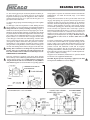
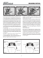
BEARING DETAIL
Figure 19B
Figure 19A
Water-Cooled
PLXC Pillow Block
Plain PLXC
Pillow Block
Dodge Sleevoil Pillow Block Bearings – (Sizes 3-15/16" thru 8" PLXC)
INSTALLATION
Tap collar up to face of lower liner allowing a total of .008"
to .016" running clearance and tighten set screws. Collar should
run parallel to end face of liner within 002". See Axial Clearance
Table V, Page 19.
The design of this pillow block allows the use of the PLXC liner. This
is accomplished by using a universal grommet for the application.
Complete basic pillow block assemblies are shipped in two packages;
the housing and associated parts are in one package and the liner
in the other. Any optional accessories are packaged separately.
9. Apply oil to bearing surface of liner cap. Locate cap in place on
lower liner, making sure oil rings are in their cavities and are free
to rotate. Install and tighten cap screws.
Before mounting the pillow block read all instructions in this
manual to become familiar with the mounting procedure and
pillow block parts nomenclature.
10. Tighten housing base to pedestal.
11. Thread dust seal and seal retainer into groove at the end of
housing base and around shaft. Slide free end of seal retainer
thru clasp and pull tightly. Hold clasp with long nose pliers and
pull free end of retainer as tightly as possible with another pair
of pliers. Cut off excess material and press down clasp lip. Seal
retainer may be disengaged by inserting a straightened paper clip
between the bands at the clasp and pulling the free end of the
retainer out of the clasp.
1. Check mounting structure making sure it is rigid, level and well
supported. Inspect shaft to insure it is smooth (32 micro-inch
finish or better), within commercial tolerances and free of burrs
or rough spots.
2. Disassemble and thoroughly clean all parts of the pillow block.
Housing caps and liner caps are matched to their bases and
should not be interchanged. Housing and liners should be
interchanged as assemblies only.
12. Apply 515 Gasket Eliminator to SLEEVOIL housing base along
outer contour of joint. Note: Special care should be taken at
grommet area. Loosen plunger screw and locate housing
cap on base taking care not to damage dust seals or gasket
material. Tighten housing bolts then turn plunger screw down
snugly. The plunger screw must be loose until the housing
bolts have been tightened.
3. Position housing base on pedestal so that oil gage is in the
position specified on the construction drawing. Do not tighten
housing base to pedestal. Apply oil to the spherical seats in the
housing base.
4. Note location of thermocouple holes in liner base. Set liner
base in housing base so thermocouple holes in housing align with
holes in liner. Thermocouple holes in housing base are on side
opposite oil gage holes (oil gage side of housing base is marked
"X"). Apply oil to liner bearing surface.
Cap Loaded Bearings: If shaft must be held down to install cap,
tighten plunger screws tightly with shaft held down. Mark position of plunger screw. Loosen plunger screw one complete turn
and loosen shaft hold-down. Then tighten plunger screw while
tightening shaft hold-down until plunger screw is tightened to
the mark. Do not over-tighten shaft hold-down as this can misalign the bearing. Remove shaft hold-down and tighten plunger
screw locknut. Torque per Table IV, Page 19.
5. Apply oil to shaft in the bearing area and set shaft in place.
6. Check alignment of pillow block by noting clearance between
housing and shaft at each end of the housing. Clearance should
be uniform within 1/32". Use shims under base as required.
Alignment of pillow block should be as accurate as possible. The
self-alignment feature of the unit is to compensate for normal
shaft deflection and possible settling of the supports.
Note: Do not tighten plunger screw on accompanying base
loaded bearing until cap-loaded bearing has been installed and
hold-down removed.
7. Place oil rings around outside of lower liner and over shaft.
Peen screws to insure that they are secure. Make sure rings
rotate freely on shaft.
Base Loaded Bearings: Tighten plunger screw locknut. Torque per
Table IV, Page 19.
13. Plain Liner: When using a Plain Liner (without coolant pipes),
install grommet and grommet plate over openings in the sides of
the housing. To reduce chance of oil leakage, a non-hardening
sealant may be used.
8. For Fixed Bearing: Remove clamp screws from thrust collars
and make sure cracked joint is clean. Place one collar half on
shaft so that finger groove is next to the liner base. Rotate collar
half around shaft and place other half in position. Bring halves
together at joint, making sure match at joint is perfect and insert
clamp screws. There should be no offset at collar face. Tap halves
together and tighten clamp screws. Repeat above operation for
opposite end of bearing. Assemble two collars on one bearing only.
Externally Cooled Liner: When PLXC Liners (with coolant pipes)
are to be used, install grommet and grommet plate over pipes
and tighten screws.To reduce chance of oil leakage, a nonhardening sealant may be used on pipes and housing faces.
16
BEARING DETAIL
and properties of specific oils should be referred to the lubricant
manufacturers. See Table VII and VIII, Page 19 for further
information.
14. The oil level gage may be located any distance from the pillow block by the use of a coupling and pipe of the desired
length.The extended pipe must be supported so that it remains
straight and perfectly level. Use a spirit level. Do not guess. Use
pipe sealer on all connections.
Fill the pillow block with oil to the top of the center circle in the
oil gage. After placing into operation, remove inspection covers
and check to make sure oil rings are bringing up oil. Operation
should be checked frequently during the first few days. If noise
develops, check alignment of housing, collar runout, plunger
screw and all operating parts. Check all points and make sure all
screws and nuts are tightened after several days operation.
Drain, flush and refill with oil after 2 to 3 weeks of operation and
every 3 months thereafter for continuous service and every 6
months for 8 hours a day service. Visually check the oil for contamination periodically between oil changes. Maintain oil level
above bottom of center circle at all times while unit is in
operation.
15. Remove all pipe plugs and reinstall using pipe sealer. Tighten
securely.
16. Make pipe connections required for coolant, making sure that
all pipe lengths are correct and unions are well aligned. Careless
fitting will result In serious preloading of bearing. Lengths of
flexible hose between pillow block and rigid piping are recommended to avoid preloading of bearing. A regulating valve should
be placed ahead of the inlet and a slight drain at the outlet for liquid coolants. The recommended method of pipe connection for
liquid coolants is to connect the inlet to one pipe and the outlet
to the other pipe on the same side of the bearing. A return is then
used to connect the two pipes on the other side of the bearings
(See Figure 20). Adjust coolant flow rate specified on construction drawing or to suit conditions. See Table VI on Page 19. When
using air as the cooling medium, connect an inlet to each pipe on
one side of the bearing and an outlet to the pipes on the other side.
For water cooled bearings, check fan general assembly drawing.
Use flow rate shown in Table VI as a general starting point for
proper cooling. Lower coolant inlet temperature and (or) lower
ambient temperature require less flow. If the coolant inlet temperature exceeds 90F, additional coolant will be required.
Antifreeze type additives may be used with the water in cold
operating environments, otherwise purge all coolant from the
liner by blowing out with compressed air or steam anytime bearing coolant is subject to freezing.
Warning: Water cooled sleeve bearings must be protected from
freezing. If they are to remain idle in freezing temperatures, the
liner water chambers must be blown clear with compressed air.
LUBRICATION and OPERATION
Any questions on installation, maintenance or operation should
be referred to the equipment manufacturer.
Since the satisfactory operation of the pillow block depends
almost entirely on the oil film being maintained between the shaft
and liner bearing surface, it is recommended that a high grade
straight mineral oil with rust and oxidation (R & 0) inhibitors
and antifoam agents be used. Information regarding qualities
CAUTION: High air pressure may damage equipment. The fluid
or air pressure should never exceed 120 p.s.i.
Figure 21
Figure 20
PLXC PILLOW BLOCKS – 3-15/16" and LARGER
PLXC LINER ASSEMBLY
Figure 22
17
BEARING DETAIL
Figure 23
SLEEVOIL RTL Pillow Blocks are designed for applications requiring
a bearing with high thrust load capacities. RTL water or air cooled
pillow blocks are available in expansion or non-expansion types and
can be modified for circulating oil.
Figure 24
Dodge Sleevoil RTL Pillow Block Bearings – (Sizes 3-7/16" thru 10")
INSTALLATION
The installation of this bearing is essentially the same as the
PLXC bearing on Page 16. The difference is that the RTL bearing
has a single thrust collar in the center with thrust plates on each
side. Proceed with installation per Sections 1-3 Page 16, then:
(half with two milled slots in steel back) against thrust collar,
making sure babbitt faces the thrust collar. Clean and oil the
second thrust plate set and install in the same manner. It may be
necessary to move the shaft slightly to obtain enough clearance
in the liner cavity to install the lower thrust plate half. (Caution:
the bearing is not yet fastened in place and can be moved).
4. Set liner base in housing base. When using circulating oil or a
thermocouple make sure the holes in the liner will align with the
holes in the housing when the pillow block is assembled. Apply
oil to the liner-bearing surface.
Note: Thrust collar clearances for all size RTL Bearings are
.015 - .030.
8. Apply oil to the bearing area of the liner cap. Locate liner cap
on liner base (cap is not reversible on base). Make sure oil rings
rotate freely. End faces of liner should have no appreciable offset.
Install and tighten cap screws alternately. If liner cap on the
non-expansion bearing will not drop into place, remove it and
reposition thrust plates tightly against thrust collar. Then reinstall liner cap.
5. Inspect shaft to insure it is smooth (32 micro-inch or better),
within commercial tolerances and free of burrs or rough spots.
If bearing used is a non-expansion (fixed) type, check thrust
collar for burrs and scratches. Use crocus cloth (not emery) to
smooth any scratches on thrust collar faces. If clamp-on type
thrust collar is used, it should now be installed. Remove jam
screws and back off set screws so they do not protrude into the
I.D. of the thrust collar. Remove clamp screws and make sure
joints of thrust collar are clean. Place both halves of thrust
collar into shaft groove and tighten clamp screws alternately and
evenly. See Table IV, Page 19. The collar faces should be smooth
with no offsets at the split. Tighten the set-screws, see Table IV,
Page 19. Install and tighten the jam screws. Oil shaft in the
bearing area and set shaft in place. The thrust collar must be
centered in the cavity of the liner base.
Caution: If it ever becomes necessary to remove liner cap,
make certain that both upper thrust plate halves remain In
place next to the thrust collar. If a plate half should remain In
the liner cap It can drop from the liner and cause injury.
9. Check alignment of pillow block by noting clearance between
housing bore and shaft at each end of the housing. Clearance
should be uniform within 1/32". Use shims under base as required. Alignment of the pillow block should be as accurate as
possible. The self-alignment feature of the unit is to compensate
for normal shaft deflection and possible settling of the supports.
6. Place oil ring around outside of liner base and over shaft.
Install and peen oil ring screws to insure they are secure. Make
sure rings rotate freely on shaft. Note: Do not use oil rings if
liner cap has baffles installed In the oil ring grooves.
10. Tighten mounting bolts securely. Shaft should rotate freely.
11. Wrap the O-ring (rubber cord) around the shaft in the seal
area and cut it to fit the shaft. Disassemble one seal and place
one half on shaft with finger facing liner. Locate O-ring in seal
groove and rotate seal half around shaft into housing base
groove. For most effective sealing, ends of O-ring must meet.
Cementing ends together is recommended. Install other half of
seal and tighten screws. Install second seal in same manner.
7. For Non-Expansion Bearings: Clean one set of the babbitt
faced thrust plates. Note that the plates are matched halves
and must not be interchanged. Carefully smooth any scratches
on babbitted face with crocus cloth (not emery cloth or sandpaper). Oil plate halves generously. First install the plate half
without milled slots in the steel back. Press the babbitted face
against the thrust collar and rotate plate around shaft into liner
cavity. Install retainer washer in groove in liner base. Rotate plate
until stopped by retainer washer. Place other thrust plate half
Continue with Sections 12-16 on Pages 16 and 17 of the PLXC
instructions. See Table IV, Page 19 for Plunger Screw Torque
information.
18
BEARING TABLES
Table lV
Table VlI
PLXC and RTL SLEEVOIL SCREW and TORQUE VALUES
REQUIRED OIL VISCOSITY*
Room Temp.
Speed
During Start-Up
Thrust Collar
Clamp Screw
Plunger Screw
Set Screw
Below –10°
All
Consult Equipment
Manufacturer
300
350
400
–10°F to 32°F
All
SAE 10
32°F to 70°F
Low
High
SAE 20
SAE 10
5/8
5/8
5/8
450
450
500
Above 70°F
Low
SAE 30
High SAE 10 – Light Loads
High SAE 20 – Heavy Loads
1750
1750
1750
3/8
1/2
1/2
850
1250
1250
3/4-10NC
7/8-9NC
7/8-9NC
1-8NC
1750
3500
4100
5000
1/2
5/8
5/8
5/8
1250
2500
2500
2500
160
160
160
5/16-24NF
5/16-24NF
5/16-24NF
160
160
160
3/8
3/8
1/2
850
850
1260
325
580
1425
5/16-24NF
3/8-16NC
3/8-16NC
160
275
275
5/8
5/8
5/8
2500
2500
2500
1425
1425
2800
5000
3/8-16NC
5/8-11NC
5/8-11NC
5/8-11NC
275
1200
1200
1200
5/8
3/4
3/4
3/4
2500
3600
3600
4800
Sleeveoil
Size
Screw Size Wrench Torque Screw Size Wrench Torque Wrench Size Wrench Torque
(Soc. Hex)
(In-Lbs)
(Soc. Hex)
(In-Lbs)
(Soc. Hex)
(In-Lbs)
1-15/16
2-3/16
2-7/16
1/4-20NC
5/16-18NC
5/16-18NC
160
325
325
5/16-18NC
7/16-14NC
7/16-14NC
140
350
350
5/8
5/8
5/8
2-11/16
2-15/16
3-7/16
3/8-16NC
3/8-16NC
1/2-13NC
580
580
1425
1/2-13NC
1/2-13NC
5/8-11NC
600
600
1200
3-15/16
4-7/16
4-15/16
1/2-13NC
1/2-13NC
1/2-13NC
1425
1425
1425
3/4-10NC
3/4-10NC
3/4-10NC
5-7/16
6
7
8
1/2-13NC
5/8-11NC
5/8-11NC
3/4-10NC
1425
2800
2800
5000
3-7/16 RTL
3-15/16 RTL
4-7/16 RTL
1/4-20NC
1/4-20NC
1/4-20NC
4-15/16 RTL 5/16-18NC
5-7/16 RTL 3/8-16NC
6 RTL
1/2-13NC
7 RTL
8 RTL
9 RTL
10 RTL
1/2-13NC
1/2-13NC
5/8-11NC
3/4-10NC
SAE Oil Required
* If not specified by equipment manufacturer.
Oil film temperature in liner during operation should
not exceed 180°F. If in doubt, consult equipment
manufacturer. Use high grade, high quality, well
refined petroleum oils of the straight mineral type,
with rust and oxidation inhibiter and anti-foam agent
only.
Approximate Viscosity:
SAE 10 – 183 SUS at 100°F; 46 SUS at 210°F
SAE 20 – 348 SUS at 100°F; 57 SUS at 210°F
SAE 30 – 489 SUS at 100°F; 65 SUS at 210°F
Table V
Table VllI
PLXC SLEEVE BEARINGS AXIAL CLEARANCES BETWEEN
LINER AND COLLARS
RECOMMENDED TURBINE GRADE
OILS - ASTM D-943 (1800 Hrs.)
TOTAL CLEARANCE
(inches)
Bearing Size
(inches)
Minimum
Maximum
1-7/16
1-11/16
1-15/16
.005
.006
.006
.009
.012
.012
2-3/16
2-7/16
2-11/16
.008
.008
.008
.014
.014
.014
2-15/16
3-7/16
3-15/16
.008
.008
.008
.014
.014
.014
4-7/16
4-15/16
5-7/16
.008
.010
.010
.014
.016
.016
6
7
8
.010
.010
.010
.016
.016
.016
Note: Thrust collar clearance for all size RTL
bearings is .015-.030 inches.
RECOMMENDED
SYNTHETIC OILS
Texaco
Designation
Bearing
Temperature
SAE
Viscosity
(or equivalent)
100° - 160°F
160° - 170°F
170° - 180°F
20
30
40
Regal R&O- 68
Regal R&O-100
Regal R&O-150
Bearing
Temp.
Mobil 632
Mobil 634
210°F
100°F
115 SSU
1535-1704 SSU
148 SSU
2215-2460 SSU
Table VI
PLXC BEARING SPECIFICATIONS
(1)
(2)
(3)
(4)
(5)
Pressure Oil Flow
Drop Reqd. Rate for
Air Cooling Circ. Oil
(PSI)
(PSI)
Pillow
Block
Size
Max. RPM
for Ring
Oiling
Water
Flow
(GPM)
Air
Flow
(CFM)
3-15/16
4-7/16
4-15/16
2910
2582
2321
1.75
2.25
2,50
52
63
77
.19
.22
.11
5-7/16
6
7
8
2107
1910
1637
1432
3.00
4.00
5.00
6.50
90
104
156
173
.12
.18
.40
.50
(6)
Oil Volume
Fluid Oz.
Qts.
Approx.
Liters
Approx.
3.0
3.5
3.5
50
64
90
1-1/2
2
2-3/4
1.45
1.90
2.70
5.0
5.5
6.5
7.5
100
132
240
320
3-1/8
4-1/8
7-1/2
10
2.95
3.90
7.10
9.5
(1) Converted from 3000 FPM Speeds above 3000 require Circulating Oil.
(2) Based on 90°F ambient temperature and 90° water inlet temperature. Cooler ambient and/or water inlet
temperatures require less flow. Pressure drop across bearing approximately 1 P.S.I.
(3) Based on 90°F ambient and 90° air inlet temperatures. Cooler ambient and/or air inlet temperatures
require less flow.
(4) Minimum back pressure required for proper air circulation through the liner coolant chambers.
(5) Flow rate required at 120°F oil inlet temperature, 90°F ambient air temperature and at 6000 FPM shaft
speed under maximum radial load. Slower speeds and lighter loads require less flow.
(6) Volume of oil required to fill pillow block to top of center circle in oil gauge. Applies to both XC and Plain
Pillow Blocks. 32 fluid oz. = 1 qt. = .94636 liters.
19
BEARING DETAIL
Solid Pillow Block Spherical Roller Bearings
Link Belt Series B22400 and B22500 or SKF Series SYR
IMPORTANT – Read Carefully
moderate loads and speeds, the shaft should measure as follows.
These instructions are provided to aid in the proper installation,
operation and maintenance of spherical roller bearing units. They
should be carefully read and followed. Failure to do so may
result in unsatisfactory service as well as serious personal
Injury or property damage.
SHAFT DIAMETER
1/2” thru 2”
2-1/16" thru 4"
4-1/16" thru 5"
RECOMMENDED TOLERANCE
Nominal to minus .0005"
Nominal to minus .0010"
Nominal to minus .0015"
2. Shaft Preparation - When frequent removal of bearings is
anticipated, file flats on the shaft approximately 1/16” deep
under the collar set screw locations. This provides for easy
removal, as bearings will clear the burrs caused by correctly
tightened set screws.
CAUTION
The reliability built in all Link-Belt bearings can be realized in
service only when they are correctly selected, properly installed,
protected and maintained.
The correct selection of bearings or mounted units requires that
the magnitude and nature of all loads, speeds, alignment, mounting, operating requirements and maintenance be adequately considered. The selection of materials for and design of housings,
shafting, fasteners, seals, accessories, as well as provisions for installation and maintenance, must follow good engineering principles.
3. Lubricate Shaft & Bearing Bore - Coat the shaft and bearing
bore with grease or oil to facilitate assembly.
Housings must be selected and installed with regard to the
degree and direction of the forces that will occur. Housings
should not be used under tension loads except with adequate
safety factors. For this reason pillow blocks are best suited to
withstand radial loads passing through the base. When heavy
loads or shock loads are possible, it is important to mount a unit
so that the line of force passes directly into its base, or so that the
unit is directly and substantially supported other than through its
mounting bolts. Where the line of force falls outside the base,
such as with horizontal or uplift loads on pillow blocks, serious
housing and fastener deflection or failure may occur. These conditions may require designs using different materials, fasteners,
mounting design, stop bars, etc. together with proper safety factors.
5. Bolt Fixed or Locating Unit to Support - Bolt fixed unit
securely to its support. Bolt grade selection is important on many
applications depending on load and shock conditions. SAE Grade
5 mounting bolts properly torque can be used. Grades over SAE
5 should not be used with cast iron housings.
4. Assemble on Shaft - If it is necessary to tap or press units on
the shaft, use a hardwood block, soft steel bar or tube against
the end of the inner ring. Do not strike or exert pressure on housing or seals.
6. Final Positioning - Establish final shaft position and secure
locking collar or fixed unit to shaft. Tighten collar set screws to
the torque values given in Table IX.
Table IX
SET SCREW TIGHTENING TORQUE
Shaft Size (in.) Seating Torque (in/lbs)* * Values can vary ± 5%
3/4 to 1-1/4
1-5/16 to 2
2-1/16 to 2-1/4
2-5/16 to 3-1/2
3-9/16 to 5
The following general points of installation and operation are
very important.
A. Cleanliness - Keep dirt, water and metal chips off all parts.
B. Careful Handling - Hammer blows or improper use of force
can damage precision parts.
125
225
325
475
1150
Note: Satisfactory tightness can
be obtained using a standard hex
wrench (50-52 minimum RHN C)
and tightening until a slight
permanent twist is obtained in
wrench for each screw.
7. Bolt Expansion or Other Unit to Support - If an expansion
unit is used, position the cartridge in the housing to allow for
adequate movement in the direction of expected expansion. Align
and shim the housing as necessary to place the bearing in the
approximate centers of their housing alignment range. Bolt unit
securely to its support (Reference step 5).
C. Shaft Fits - Bearings should have proper shaft fits to minimize
fret wear. See installation instructions for shaft tolerances.
D. Bolts - Housing mounting bolt tightness is important to prevent the housing from shifting, and to adequately support loads.
E. Set Screws - Set screws must be properly torqued to prevent
the shaft from slipping in the inner ring and to prevent loosening
during operation.
8. Final Mounting - Rotate shaft slowly, under load if possible,
for several revolutions to properly center the roller elements with
respect to the raceways. Securely tighten collar set screws of
remaining bearing, following the same procedure as outlined
under step 6.
F. Free Rotation and Alignment - Check for free rotation before
machine start-up to assure that final alignment is proper.
Although bearings are alignable in housings, they will not "selfalign" in many cases and destructive moment loads may be imposed if initial installation alignment is not provided.
9. Check System for Freedom of Rotation - Any condition of
strain, irregular rotational torque, abnormal sound or vibration
may be due to improper alignment, improper location, bent shaft,
distorted supports, etc. Installation should be rechecked and corrections made as required.
G. Lubrication - Units designed for relubrication must be adequately lubricated. A bearing not properly lubricated can run to
destruction and possibly cause damage to other components.
Add grease slowly. Rapid application may blow the seals and
allow grease to escape.
The use of stop bars welded to the support at each end of the
units leaving about 1/32" space for ease of assembly is good
practice. Wedge shims in 1/32"-space after units are securely
fastened. These bars assure proper location of the units and
prevent shifting when loads are applied.
INSTALLATION
1. Check Shaft - Shafting must be clean, round, straight, free of
burrs and nicks and of correct size. For the average installation with
20
BEARING DETAIL
LUBRICATION
The specific conditions on an application such as exact hours of
operation, temperature, moisture, speed and dirt govern the
required lubrication cycle. This can be determined by inspection of
the flushed out lubricant during a trial period of operation. Add
grease slowly. Use a sufficient volume of grease to purge bearing
seals of old lubricant. It is preferable to rotate bearings during
relubrication where good safety practice permits.
Units are prelubricated with lithium base NLGI #2 grade grease, but
make sure they have adequate grease. As a precaution, if equipment
is to be built and left idle for any period of time prior to actual use,
the units should be filled 100% full to provide maximum protection
from corrosion, etc. The suggested relubrication schedule under
Table X is a general guide.
Inspect bearing installations at least every six months. Any unusual
noise or vibration change should be immediately investigated.
Table X – BEARING GREASE
AMBIENT
CONDITIONS
Dirt
Clean
Moisture
Dry
Moderate
to Dirty
Dry
Extreme
Dirt
Dry
*
High
Humidity Direct
Water
Splash
OPERATING
CONDITIONS
Load
Speed
BEARING OPERATING
TEMPERATURE (°F)
Low
High
0
SUGGESTED
GREASING INTERVAL**
Light to
Medium
Slow to
Medium
120
120
200
2 to 6 Months
1 to 2 Months
Light to
Medium
Slow to
Medium
0
120
120
200
1 to 4 Weeks
1 to 7 Days
Light to
Medium
Slow to
Medium
0
200
Daily Flushing Out Dirt
Light to
Heavy
Slow to
Medium
32
200
1 to 4 Weeks Grease at Shutdown
0
– 20
200
1 to 8 Weeks
120
1 to 8 Weeks
Slow
Heavy to
Very Heavy
USE THESE GREASES
or EQUIVALENT
High quality NLGI #1 or #2 multi-purpose
bearing greases are generally satisfactory.
Consultation with a reputable lubricant
supplier is recommended.
Mobil Oil Corporation, Mobilith AW-2
Texaco Inc., Premium RB2
Shell Oil Company, Alvania EP2
Shell Oil Company, Alvania EP2
Mobil Oil Corporation, Mobiltemp 78
Amoco, Rykon No. 2
Texaco Inc., Premium RB 2
Light
High
Speed
100
200
1 to 8 Weeks
Possible
Frost
Light to
Heavy
Slow to
Medium
– 65
250
1 to 4 Weeks Grease at Shutdown
Clean to
Moderate
Dry
Light to
Medium
Slow to
Medium
80
250
1 to 8 Weeks
Union Oil Company, Unoba EP2
Mobil Oil Corporation Mobiltemp 78
Clean to
Dirty
Dry
Light
Slow
80
300
1 to 4 Weeks
Keystone Lubricants Company, No. 89
Dow Chemical Company, DC44
* Additional bearing protection or special sealing may be required.
** Suggested starting interval for maintenance program. Check grease condition
for oiliness and dirt and adjust greasing frequency accordingly. Watch operating
temperatures. Sudden rises may show need for grease or indicate over lubrication on higher speed applications.
Mobil Oil Corporation, Mobiltemp SHC32
Texaco Inc., 2346EP Low Temp
Shell Oil Company, Aeroshell 7A
Chicago Blower Corporation cannot be held responsible for performance of individual
batches of grease. Changes in lubricant specifications, performance, and lubricant
guarantees are the responsibility of the lubricant manufacturer.
Spherical Roller Adapter Bearing - Center Hung Wheels (refer to Pages 22 and 23)
Figure 29A
21
BEARING DETAIL
Split Pillow Block Spherical Roller Bearings
Link Belt Series 6800 or SKF Series SAF 22500
5. Position on Shaft - Locate the bearing and sleeve snugly on
the shaft in the desired position. Fixed bearings are located with
the bearing face opposite the locknut up against the housing
shoulder. Expansion bearings are usually centered in the housing
seat between the shoulders to allow for shaft expansion or
contraction. A shaft with a pair of bearings normally has one
fixed and one expansion pillow block. The fixed unit is usually located adjacent to the drive. The fixed bearing takes any thrust
loads. In locating, take into account that tightening correctly will
move the bearing further up the tapered sleeve. Do not tighten
locknut beyond finger tight at this time.
IMPORTANT – Read Carefully
These instructions are provided to aid in the proper installation,
operation and maintenance of spherical roller bearing units. They
should be carefully read and followed. Failure to do so may
result in unsatisfactory service as well as serious personal
Injury or property damage.
The following general points of installation and operation are
very important.
A. Cleanliness - Keep dirt, water and metal chips off all parts.
B. Careful Handling - Hammer blows, overheating or improper
use of force can damage precision parts.
6. Install Shaft Assembly - The shaft with bearing assemblies
may be lowered into housing bases before or after tightening the
bearings, depending on accessibility. Lower slowly and position
bearings and seals to engage housing base. If bearing outer rings
become misaligned do not force back into position. Instead, carefully work back by turning and sliding. Be sure that the inside of
the housing is clean.
C. Adapter Sleeve Tightening - Bearings must be correctly
forced up their tapered adapter sleeves to obtain the recommended clearance removal. Improperly tightened bearing and
adapter assemblies may slip or turn on the shaft. See table XI.
D. Bolts - Housing mounting bolt and cap tightness is important
to prevent the housing from shifting, and to adequately support
loads.
7. Tighten Bearings - Bearings must be mounted to achieve the
required clearance removal.
E. Free Rotation and Alignment - Check for free rotation before
machine start-up to assure that final alignment is proper.
a. Measure the initial built-in clearance across the top rollers by
sliding the largest possible feeler gage between the rollers and
outer ring raceway as shown in Figure 26, Page 23. A snug, or
hard, feel is recommended. It must be possible to remove the
shim by pulling it straight out.
F. Lubrication - Units must be adequately lubricated. A bearing
not properly lubricated can run to destruction and possibly cause
damage to other components. See Table X, Page 21.
INSTALLATION
1. Preparation - Remove parts from carton but do not remove
parts from individual wrapping until ready to use. The preservative on the bearing is compatible with most petroleum lubricants
and normally need not be removed. Cap and base are machined
as matched units and are not interchangeable. Mark each before
taking apart to prevent mixing with other bases or caps. Review
fan assembly drawing to verify location of fixed and floating bearings.
2. Mount Housing Base - Use jack-screws in dowel pin holes to
disassemble base and cap. Avoid use of pry or wedge at the split
line. If oil cup or feed line is used, install at this time using sealant
on all plumbing threads. Be sure housing support plate is flat and
free from warpage. Bolt base to support square with the shaft.
Draw up base mounting bolts snugly, but not to final tightness.
Figure 25
3. Check Shaft - Shafting must be clean, round, straight, free of
burrs and nicks, and correct size. Shafts should measure as follows:
SHAFT DIAMETER
7/16” to 2”
2-1/16" to 4"
4-1/16" to 6"
6-1/16 to 13"
Table XI – BEARING CLEARANCE REDUCTION*
RECOMMENDED TOLERANCE
Nominal to minus .003"
Nominal to minus .004"
Nominal to minus .005"
Nominal to minus .006"
Shaft
Pillow Block
Diameter
Range
Range (in.)
1 7/16-1 3/4
6823-6828
1 15/16-2 3/16 6831-6835
2 7/16-2 11/16 6839-6843
2 15/16-3 1/2
6847-6856
3 11/16-4 3/16 6859-6867
4 7/16-5
6871-6880
5 3/16-5 7/16
6883-6887
5 15/16-6 1/2 6895-68104
6 15/16-7 3/16 68111-68115
7 1/2-8
68120-68128
If felt "A" seals are used, be sure that any tool marks or ridges are
removed under the seal area. For higher speed operation with felt
seals, shaft should be polished or ground to 10-20 micro-inch finish.
4. Assembly on Shaft - Slide steel seal rings, if used, bearing,
adapter and accessory parts on the shaft in the right order. See
Figure 25. Also see Figure 29A, Page 21 for A/3 and A/7 (for
center hung wheels), Figure 29B, Page 23 for A/1, A/8 and A/9
(for overhung wheels). Apply mixture of white lead and oil or a
powdered dry lubricant to tapered surface and threads of adapter
sleeve and to the inside (small) face of the locknut.
Bearing Range
22209LBK -22210LBK
22211LBK -22213LBK
22215LBK -22216LBK
22217LBK -22220LBK
22222LBK -22224LBK
22226LBK -22228LBK
22230LBK -22232LBK
22234LBK -22236LBK
22238LBK -22240LBK
22244LBK
Reduction of
Clearance (in.)
Min.
Max.
.0010
.0012
.0016
.0018
.0020
.0026
.0030
.0031
.0035
.0039
.0012
.0016
.0020
.0024
.0028
.0035
.0039
.0043
.0051
.0055
*Clearance is measured between rollers and outer race after mounting and
tightening adapter. Refer to Figure 26, Page 23
22
BEARING DETAIL
Figure 26
Figure 27
Figure 28
12 Complete Assembly – With the mounting bolts snug check
alignment and freedom of rotation. The housing or shaft
clearance at the seals is small and can be visually checked for
uniformity all the way around.
b. Tighten locknut forcing the bearing up the tapered O.D. of the
sleeve until the bearing measured clearance is reduced by the amount
shown in Table XI, Page 22. Follow tightening procedures in Step 8.
8. The preferred method of tightening for easy installation and
for not damaging the bearing is illustrated in figures 27 and 28.
Using a Spanner wrench, tighten the locknut until snug. Hold the
adapter sleeve from turning until firmly seated. Using a soft steel
bar and a hammer, drive against the face of the locknut as shown
to relieve the thread pressure. Retighten the locknut and repeat
until the correct adjustment specified in Step 7 is obtained.
Where space limitations prohibit the above method, use a heavyduty spanner wrench and stroke on its handle with a hammer so
as to tighten the unit. This is more difficult and requires care to
avoid damaging the lock washer, locknut and machined housing
surfaces. With large units a combination of both methods can be
successfully used.
Align by shimming or shifting as necessary. Use large area shims
to avoid distorting the housing and pinching the bearing. Appropriate use of stop bars against faces or ends of feet opposite the
direction of load or vibration to avoid shifting of the housing is
recommended. Dowel pins can be equally effective if properly
used. This is especially important where loads are not directly
down through the base. Finally, tighten or torque mounting bolts
securely. Up to SAE Grade 5 mounting bolts can be used, properly torqued to mount cast iron housings. Up to SAE Grade 8
mounting bolts can be used, properly torqued, to mount cast
steel housings.
9. Secure Locknut - Bend a tang of the lockwasher down into
one of the locknut slots. Use the slot that is most nearly lined up
with a tang. On larger units with a lockplate, engage the key of
the lockplate in the adapter slot and bolt to the locknut. Use wire
to lock bolts. Insert "C" spacer in fixed bearing housing, usually
on locknut side.
Grease lubrication is recommended wherever conditions in Table X,
Page 21 exist. For conditions that are not completely covered,
consult Chicago Blower Corporation. The greases listed are for
a general guide. A reputable lubricant manufacturer should be
consulted to confirm the lubricant selection and application.
GREASE LUBRICATION
If bearings require oil instead of grease due to high tip speeds,
temperature or high radial and axial thrust loads, see general
assembly drawing bearing notes, and Tables VII and VIII on Page
19 and see Page 24.
10. Lubricate - Lubricate before operation. Consult the sections
on grease or oil lubrication. Refer to Table X, Page 21.
11. Install Housing Cap - Apply non-hardening gasket compound to cap surfaces that contact the base (Especially for oil
lubrication). Tighten cap nuts or bolts securely.
Spherical Roller Adapter Bearing - Overhung Wheels
Figure 29B
23
BEARING DETAIL
OIL LUBRICATION
Oil Viscosity:
Oil Cup or Oil Bath Lubrication:
Required viscosity for good lubrication depends on starting temperatures, operating temperatures, and speed. The recomended
viscosity level for bearings operating within catalog speed limits
is between 100 and 150 Saybolt seconds (SSU) at bearing operating temperature for oil exit temperature on circulating systems.
Slow speed, heavily loaded bearings require much higher viscosities.
Oil cups can be applied to these units for use as a self-contained
oil bath system. Oil bath lubrication is not recommended for
speeds above the catalog oil speed limits, where excessive oil
churning or misting occurs, or where there is air flow across the
housing which will pull oil out through the seals due to differential pressures.
Where starting temperatures are very low compared to operating
temperatures, heaters may 'be necessary to provide oil flow in
the lines or to provide adequate lubrication at start-up.
Oil levels are controlled by sight gages, oil cups, etc. These
should be used in conjunction with a vent or breather cap. Proper
static oil levels are shown in Table XII. Cups or sight gages should
be carefully marked. See Figure 30.
Maintenance and Lubrication:
Oil cup or bath systems require close attention because of the
limited amount of oil in the system. Frequent changing of the oil
in these systems is necessary to avoid lubricant breakdown.
Circulating Oil Lubrication:
Oil circulation systems can be used under a wider variety or
under more extreme operating conditions than any other lubrication method. They are especially valuable for high speed and
high temperature service to provide better lubrication and cooler
operation. A complete circulation system includes the use of
pressure pump, a heat exchanger, or a method to cool oil, an
adequate sump, a filter to remove particles over 20 micron in size
and safety devices such as pressure and temperature warning
devices and filter bypasses. See Figure 31. It is also best to tap
oversized drain holes in the base or to provide a suction pump to
positively remove oil from the housing. Oil should be removed
from both sides of the housings, but where speeds are not high,
one side is sufficient.
Oil circulation systems, properly equipped with safety devices
require minimum attention after they are once satisfactorily
adjusted. Frequency of changing the oil in the system depends
upon the severity of the operation and size of the reservoir. In
either case summer and winter grades may be necessary to stay
within the recommended viscosity limits for good lubrication.
Table XII– STATIC OIL LEVEL (Dimensions in inches)
Bearing Size
1-7/16,1-1/2
1-11/16, 1/3/4
1-15/16, 2
2-3/16, 2-1/4
2-7/16
2-11/16
2-15/16, 3
3-3/16
3-7/16, 3-1/2
3-11/16, 3-15/16, 4
4-3/16
4-7/16, 4-1/2
4-15/16, 5
5-3/16
5-7/16
5-15/16, 6
6-7/16
6-15/16, 7
7-3/16
7-1/2, 7-15/16, 8
It is recommended that the circulation system have a separate
motor so that the oil flow can be started in advance of bearing
rotation. Experimentation with pressures, flow rates, temperatures and viscosity is often necessary to establish the best
possible bearing lubrication.
Static Oil Dimension Guide
Figure 30
B
Schematic Diagram of
Circulating Oil System
Figure 31
24
A
2-1/4
2-1/2
2-3/4
3
3-1/4
3-1/2
3-3/4
4
4-1/2
4-15/16
5-1/4
6
6
6-5/16
6-11/16
7-1/16
7-1/2
7-7/8
8-1/4
9-1/2
B
7/16
9/16
9/16
1/2
5/8
3/4
13/16
3/4
7/8
7/8
1
1-1/4
1-1/16
1-1/16
1
1-1/8
1-1/8
1-1/4
1-3/8
2-1/2
Static Oil Level Below
Bearing Centerline
L
High
Low
1-9/32
1-3/8
1-17/32
1-27/32
2-1/32
2-3/16
2-5/16
2-15/32
2-25/32
3-1/16
3-5/16
3-9/16
3-7/8
4-5/32
4-15/32
4-3/4
4-31/32
5-1/4
5-9/16
6-5/32
1-3/8
1-15/32
1-5/8
1-15/16
2-1/4
2-9/32
2-15/32
2-5/8
2-15/16
3-7/32
3-1/2
3-3/4
4-1/16
4-11/32
4-21/32
4-15/16
5-5/32
5-7/16
5-3/4
6-11/32
INSTALLATION RECORD
FAN WARRANTY
Job Site ___________________________________ System ________________________________
Fan Size ______________________ Chicago Blower Fan Serial No. __________________________
Design ____________ Class __________ Fan Assembly Drawing No. _________________________
Fan Rated CFM ___________ Fan Rated Static Pressure __________ Fan Rated BHP ___________
Maximum Operating Temperature ________°F.
Fan Maximum Operating Speed ____________
Size Bearings______________ Type __________________ Manufacturer ______________________
Size Coupling ______________ Type _________________ Manufacturer ______________________
Motor HP _________ RPM __________ Frame Size __________Manufacturer __________________
Date Fan Shipped ________ Date Installation Completed _________ Date Fan Start ______________
Name of CBC Service Engineer ____________________ Name Millwright in Charge _____________
Fan Purchased From ________________________ Installing Contractor _______________________
Chicago Blower Local Sales Office ___________________________ Phone ___________________
WARRANTY
Chicago Blower warrants products of its manufacture to be free of defects in material and workmanship for a period of one year
from the date of original shipment. This warranty is subject to the following terms and limitations:
(1)
All products must be properly installed, cared for and operated under normal conditions and with adequate supervision.
(2)
Chicago Blower will not be liable or responsible for (i) any corrosion or fouling caused by any foreign substances, or (ii) any
defects caused by adjustments, alterations or repairs made or attempted outside of Chicago Blower's factory, except upon
the prior written consent of Chicago Blower.
(3)
Since no currently known form of construction, material, alloy or coating will successfully resist all abrasion, erosion,
corrosion, or deterioration from excessive heat or vibration, this warranty does not extend to any damage or defect caused
by any of those conditions.
(4)
Research undertaken by the Air Movement and Control Association, Inc. in cooperation with test code committees of the
engineering societies reveals thus far that no practical method exists for testing the suitability of fans in a specific system.
CHICAGO BLOWER THEREFORE DOES NOT WARRANT AND SPECIFICALLY EXCLUDES ANY WARRANTY THAT ITS
PRODUCTS ARE FIT FOR A PARTICULAR PURPOSE OR USE. Responsibility for determining the fitness of our products for
intended use is the purchaser's.
(5)
The sound power and pressure data contained in Chicago Blower quotations are for a hemispherical free field condition
and comply with AMCA Standard 301, Method for Publishing Sound Ratings, and are the result of tests made in accordance
with AMCA Standard 300, Test Code for Sound Rating air moving devices. The data is in no way to be construed as a
guarantee in that the industry has not found a practical and accurate method of verifying individual equipment sound
levels by field testing.
(6)
CHICAGO BLOWER DOES NOT PROVIDE ANY WARRANTY (EXPRESS OR IMPLIED) WITH RESPECT TO COMPONENT PARTS
(MOTORS, SWITCHES, CONTROLS OR ACCESSORIES) WHICH ARE MANUFACTURED BY OTHERS. However, these products
are usually warranted separately by their respective manufacturers.
(7)
CHICAGO BLOWER DOES NOT WARRANT ITS PRODUCTS TO BE IN COMPLIANCE WITH THE OCCUPATIONAL SAFETY AND
HEALTH ACT ("OSHA") AS AMENDED OR ANY REGULATIONS THEREUNDER. Compliance with OSHA is the exclusive
responsibility of the user of the equipment.
(8)
ALL OTHER WARRANTIES, WHETHER EXPRESS OR IMPLIED, INCLUDING ANY IMPLIED WARRANTY OF MERCHANTABILITY
OR FITNESS FOR A PARTICULAR PURPOSE, ARE HEREBY EXCLUDED.
(9)
This warranty may not be modified except by written agreement signed by an officer of Chicago Blower Corporation.
LIMITATION OF LIABILITY
Chicago Blower's liability for any purpose is limited to repairing or replacing at its factory any defective part or parts which shall,
within one year after original shipment, be returned to its factory, transportation charges prepaid. Repair or replacement of
defective parts shall be the purchaser's sole and exclusive remedy. Under no circumstances will Chicago Blower be liable for
any injury to persons or property, nor will Chicago Blower be liable for any damages of any kind, whether incidental, consequential or otherwise, whether arising out of breach of contract, breach of warranty, tort liability, strict liability or otherwise. If
the goods, however, prove to be so defective as to preclude remedying the defect by repair or replacement, the purchaser's sole
and exclusive remedy and Chicago Blower's sole and exclusive liability will be refund of the purchase price. Purchaser will
defend, indemnify and hold Chicago Blower harmless against any claims for liability or damages which are made against Chicago
Blower and which are directly or indirectly related to Chicago Blower's sale of products to purchaser.
25
Sales Engineers
Your Primary Source for
Every Fan Requirement
ALABAMA
Birmingham
Mobile
ALASKA
Anchorage
Fairbanks
ARIZONA
Phoenix
Tucson
ARKANSAS
Little Rock
CALIFORNIA
Fresno
Los Angeles
Oakland
Sacramento
San Diego
San Francisco
San Jose
COLORADO
Denver
CONNECTICUT
Bridgeport
Hartford
DELAWARE
Wilmington
FLORIDA
Jacksonville
Miami
Tampa
GEORGIA
Atlanta
Augusta
Macon
Savannah
HAWAII
Honolulu
IDAHO
Boise
ILLINOIS
Champaign
Chicago
Peoria
Rockford
INDIANA
Evansville
Fort Wayne
Indianapolis
South Bend
IOWA
Davenport
Des Moines
KANSAS
Topeka
Wichita
KENTUCKY
Lexington
Louisville
LOUISIANA
Baton Rouge
New Orleans
Shreveport
MAINE
Lewiston
Portland
MARYLAND
Baltimore
MASSACHUSETTS
Boston
Springfield
MICHIGAN
Benton Harbor
Detroit
Grand Rapids
Jackson
Kalamazoo
Lansing
Muskegon
MINNESOTA
Duluth
Minneapolis
St. Paul
MISSISSIPPI
Jackson
MISSOURI
Jefferson City
Kansas City
St. Louis
Springfield
MONTANA
Billings
Great Falls
NEBRASKA
Omaha
NEVADA
Reno
NEW HAMPSHIRE
Manchester
For General Duty
Fans designed primarily for clean exhaust or supply air
applications are designated General Duty fans. Included
are controllable pitch vane axial and airfoil
centrifugal fans for HVAC systems. Chicago’s
exclusive Express Program offers many
basic fans from stock in five days.
For Industrial Duty
Chicago Industrial Fans are built to
accommodate dirty and corrosive
environments. Wheels are available
to match the duty, class and application. Fiberglass Reinforced Plastic
fans resist harsh chemical fumes,
vapors and gases.
For Heavy Duty
Larger fans modified for specific
applications as well as custom
engineered and built fans require
the expertise synonymous with
Chicago Heavy Duty Fans.
Application experience includes
refining, cement plants, utilities,
coal processing and diverse
emission control systems.
NEW JERSEY
Camden
New Brunswick
Newark
Trenton
NEW MEXICO
Albuquerque
NEW YORK
Albany
Binghampton
Buffalo
New York
Rochester
Syracuse
Utica
NORTH CAROLINA
Charlotte
Greensboro
NORTH DAKOTA
Bismark
Fargo
OHIO
Akron
Cincinnati
Cleveland
Columbus
Dayton
Toledo
Youngstown
OKLAHOMA
Oklahoma City
Tulsa
OREGON
Portland
PENNSYLVANIA
Erie
Harrisburg
Philadelphia
Pittsburgh
RHODE ISLAND
Providence
SOUTH CAROLINA
Charleston
Greenville
SOUTH DAKOTA
Rapid City
Sioux Falls
TENNESSEE
Chattanooga
Knoxville
Memphis
Nashville
TEXAS
Amarillo
Dallas
El Paso
Houston
Lubbock
San Antonio
UTAH
Salt Lake City
VERMONT
Burlington
VIRGINIA
Richmond
Roanoke
WASHINGTON
Seattle
Spokane
WEST VIRGINIA
Charleston
WISCONSIN
Eau Claire
Green Bay
Milwaukee
WYOMING
Casper
Cheyenne
WASHINGTON DC
CANADA
Calgary, Alta.
Edmonton, Alta.
Vancouver, B.C.
Winnipeg, Man.
Hamilton, Ont.
Mississauga, Ont.
Ottawa, Ont.
Saskatoon, Sask.
Toronto, Ont.
Windsor, Ont.
Montreal, Que.
Yukon
MEXICO
Mexico City
PUERTO RICO
San Juan
You can also buy Chicago fans in:
1675 GLEN ELLYN ROAD, GLENDALE HEIGHTS, ILLINOIS 60139
PHONE: (630) 858-2600 FAX: (630) 858-7172
www.chicagoblower.com E-mail: [email protected]
!
Printed On Recycled Paper
in the USA
November 2008
Argentina, Australia, Benelux, Brazil,
Chile, Colombia, Denmark, France,
Germany, Greece, Holland, Hong Kong, India,
Indonesia, Israel, Italy, Japan, Korea, Malaysia,
New Zealand, Norway, Philippines, Portugal,
Saudi Arabia, Singapore, South Africa, Spain,
Sweden, Taiwan, Turkey and Venezuela.