1
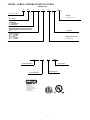
40MKCB / 24AHA4 / 124ANS
40MKQB / 25HHA4 / 224ANS
High---Wall Ductless Split System
Sizes 18 to 32
Service Manual
TABLE OF CONTENTS
PAGE
SAFETY CONSIDERATIONS . . . . . . . . . . . . . . . . . . . . . . . . . 1
INTRODUCTION . . . . . . . . . . . . . . . . . . . . . . . . . . . . . . . . . . . 1
MODEL / SERIAL NUMBER NOMENCLATURES . . . . . . . . 2
STANDARD FEATURES AND ACCESSORIES . . . . . . . . . . . 3
SPECIFICATIONS . . . . . . . . . . . . . . . . . . . . . . . . . . . . . . . . . . 4
DIMENSIONS . . . . . . . . . . . . . . . . . . . . . . . . . . . . . . . . . . . . . . 5
CLEARANCES . . . . . . . . . . . . . . . . . . . . . . . . . . . . . . . . . . . . . 6
ELECTRICAL DATA . . . . . . . . . . . . . . . . . . . . . . . . . . . . . . . . 7
POWER AND CONNECTING CABLES . . . . . . . . . . . . . . . . . 8
CONNECTION DIAGRAMS . . . . . . . . . . . . . . . . . . . . . . . . . . 9
REFRIGERATION CYCLE DIAGRAMS . . . . . . . . . . . . . . . . 13
REFRIGERANT LINES . . . . . . . . . . . . . . . . . . . . . . . . . . . . . 14
SYSTEM EVACUATION AND CHARGING . . . . . . . . . . . . . 14
SEQUENCE OF OPERATION . . . . . . . . . . . . . . . . . . . . . . . . 15
TROUBLESHOOTING . . . . . . . . . . . . . . . . . . . . . . . . . . . . . . 16
APPENDIX . . . . . . . . . . . . . . . . . . . . . . . . . . . . . . . . . . . . . . . 24
WARNING
!
ELECTRICAL SHOCK HAZARD
Failure to follow this warning could result in personal
injury or death.
Before installing, modifying, or servicing system, main
electrical disconnect switch must be in the OFF
position. There may be more than 1 disconnect switch.
Lock out and tag switch with a suitable warning label.
!
EXPLOSION HAZARD
Failure to follow this warning could
result in death, serious personal injury,
and/or property damage.
Never use air or gases containing
oxygen for leak testing or operating
refrigerant compressors. Pressurized
mixtures of air or gases containing
oxygen can lead to an explosion.
SAFETY CONSIDERATIONS
Installing, starting up, and servicing air--conditioning equipment
can be hazardous due to system pressures, electrical components,
and equipment location (roofs, elevated structures, etc.).
Only trained, qualified installers and service mechanics should
install, start--up, and service this equipment.
Untrained personnel can perform basic maintenance functions such
as cleaning coils. All other operations should be performed by
trained service personnel.
When working on the equipment, observe precautions in the
literature and on tags, stickers, and labels attached to the
equipment.
Follow all safety codes. Wear safety glasses and work gloves. Keep
quenching cloth and fire extinguisher nearby when brazing. Use
care in handling, rigging, and setting bulky equipment.
Read this manual thoroughly and follow all warnings or cautions
included in literature and attached to the unit. Consult local
building codes and National Electrical Code (NEC) for special
requirements. Recognize safety information. This is the safety--alert
symbol !! . When you see this symbol on the unit and in
instructions or manuals, be alert to the potential for personal injury.
Understand these signal words: DANGER, WARNING, and
CAUTION. These words are used with the safety--alert symbol.
DANGER identifies the most serious hazards which will result in
severe personal injury or death. WARNING signifies hazards
which could result in personal injury or death. CAUTION is used
to identify unsafe practices which may result in minor personal
injury or product and property damage. NOTE is used to highlight
suggestions which will result in enhanced installation, reliability, or
operation.
WARNING
!
CAUTION
EQUIPMENT DAMAGE HAZARD
Failure to follow this caution may result in equipment
damage or improper operation.
Do not bury more than 36 in. (914 mm) of refrigerant pipe
in the ground. If any section of pipe is buried, there must be
a 6 in. (152 mm) vertical rise to the valve connections on
the outdoor units. If more than the recommended length is
buried, refrigerant may migrate to the cooler buried section
during extended periods of system shutdown. This causes
refrigerant slugging and could possibly damage the
compressor at start--up.
INTRODUCTION
This Service Manual provides the necessary information to service,
repair, and maintain the MK family of air conditioners and heat
pumps. Section 2 of this manual is an appendix with data required
to perform troubleshooting. Use the Table of Contents to locate a
desired topic.
MODEL / SERIAL NUMBER NOMENCLATURES
INDOOR UNIT
40
MK
C
B
18
B
--- ---
3
40= FAN COIL UNIT
VOLTAGE
3 = 208/230 ---1 ---60
MK = MODEL
SYSTEM TYPE
C = COOLING ONLY
Q = HEAT PUMP
MAXIMUM NUMBER OF FAN COIL UNITS THAT
CAN BE CONNECTED TO THE OUTDOOR UNIT
B=1:1
NOT USED
NOMINAL CAPACITY
18 = 1--- 1/2 TONS
22 = 1--- 5/6 TONS
24 = 2 TONS
28 = 1--- 1/3 TONS
32 = 2--- 2/3 TONS
INDOOR FAN COIL TYPE
B= HIGH ---WALL
01
15
V
00001
Week of Manufacture
Serial Number
Manufacturing Site
Year of Manufacture
Use of the AHRI Certified
TM Mark indicates a
manufacturer’s
participation in the
program For verification
of certification for individual
products, go to
www.ahridirectory.org.
®
2
STANDARD FEATURES AND ACCESSORIES
INDOOR UNIT ACCESSORIES
Table 1—Standard Features
Ease Of Installation
Indoor and Outdoor Compact Size
Outdoor Unit Wall Mounting Kit
Outdoor Unit Stacking Kit
Indoor Mounting Bracket
Comfort Features
Microprocessor Controls
Wireless Remote Control
Automatic Air Sweep
Air Direction Control
Auto Restart Function
Cold Blow Protection On Heat Pumps
Turbo Mode
Silence Mode
Follow Me
Energy Saving Features
Sleep Mode
Stop/Start Timer
46 ° F Heating Mode (Heating Setback)
Safety And Reliability
3 Minute Time Delay For Compressor
Over Current Protection For Compressor
Crankcase Heater (standard on size 30 Heat Pump)
Indoor Coil Freeze Protection
Indoor Coil High Temperature Protection On Heat Pumps
Condenser High Temperature Protection On Heat Pumps
Accumulator On Heat Pumps
Ease Of Service And Maintenance
Cleanable Filters
Diagnostics
Liquid Line Pressure Taps
Suction And Discharge Pressure Taps
Application Flexibility
Low Ambient Controls (--20_ F) (--28.9 _C)
3--Phase on size 32 (Cooling Only)
Wind Baffles
Condensate Pumps
Wired Controls
Legend
S Standard
A Accessory
S
A
A
S
Condensate Pump
S
S
S
S
S
S
S
S
S
S
S
S
S
S
A
S
S
S
S
S
S
S
S
A07892
Fig. 1 – Condensate Pump Accessory
On high wall fan coils, the condensate pump has a lift capability of
12 ft (3.6 m) on the discharge side with the pump mounted in the
fan coil or 6 ft (1.8 m) on the suction side if the pump is remote
mounted. The pump is recommended when adequate drain line
pitch cannot be provided, or when the condensate must move up to
exit.
Wired Remote Controller
For applications where the use of wireless remote control is not
desired, the MK units can be controlled by means of a wired
wall--mounted control with an LCD display.
A
S
A
A
A
Table 2—Accessories
Part Number
KSACN0101AAA
53DS--900------118
KAAVC0101AAA
KHAVC0101AAA
Description
Wired Remote Control
Condensate Pump (230v)
Controls Kit (Required on High Walls
Cooling Only units)
Controls Kit (Required on High Walls
Heat Pump units)
KSALA0801AAA
Low Ambient Control (for cooling --20F)
KSALA0901AAA
Low Ambient Control (for cooling --20F)
KAACH1401AAA
Crankcase Heater
KAACH1501AAA
Crankcase Heater
KAACH1701AAA
Crankcase Heater
KAAWS0101AAA
KHAIR0201AAA
Winter Start Kit (for low ambient on
cooling only systems)
Isolation Relay (Required when using
Low Ambient cooling with HP)
KSAHS1501AAA
Hard Start Kit (Capacitor & Relay)
53DS--900------087
Wind Baffle
53DS--900------071
Wind Baffle
53DS--900------075
53DS--900------076
Stacking Kit
Stacking Kit
53DS--900------077
Wall Mount Kit
53DS--900------078
Wall Mount Kit
KAALS0201LLS
Liquid Line Solenoid for Cooling Only
KHALS0401LLS
Liquid Line Solenoid for Heat Pump
For Models
Only Sizes 18, 22
All Sizes
40MKC
40MKQ
24AHA4/25HHA4
/124ANS/224ANS (208/230V)
24AHA4 /124ANS (460V--3)
24AHA4/124ANS Sizes 18--36
(208/230V)
24AHA4/124ANS Size 36
(460V--3)
25HHA4/224ANS Size 24
(208/230V)
Fig. 2 – Wall Mounted Control with LCD Display
24AHA4/124ANS All Sizes
25HHA4/224ANS All Sizes
24AHA4/25HHA4
/124ANS/224AN S (208/230V--1)
24AHA4/124ANS Sizes 18 & 24;
25HHA4/224ANS Size 24
24AHA4/124ANS Sizes 30 -- 36;
25HHA4/224ANS Size 30
24AHA4/124ANS Sizes 18, 24
24AHA4/124ANS Sizes 30, 36
24AHA4/25HHA4/124ANS/224A
NS Sizes 18, 24
24AHA4/25HHA4
/124ANS/224ANS Sizes 30, 36
24AHA4/124ANS All Sizes -Required for Long Line
Applications
25HHA4 /224ANS All Sizes -Required for Long Line
Applications
3
SPECIFICATIONS
Table 3—Specifications
Size
System
Outdoor Model
Indoor Model
Cooling Rated Capacity
SEER
EER
Performance
Heating Rated Capacity
HSPF
COP
Controls
Operating
Range
Piping
Refrigerant
Outdoor
Coil
Indoor
Coil
Compressor
Btu/h
Standard
Standard
Standard
Optional
Optional
N/A
W/W
Wired Remote Controller (° F/° C
Convertible)
Cooling Outdoor DB Min -°F
Max
Heating Outdoor DB Min -°F
Max
Cooling Indoor DB Min
°F
--Max
Heating Indoor DB Min
°F
--Max
Total Piping Length**
Ft.
Drop (OD above ID)
Ft.
Lift (OD below ID)
Ft.
Outdoor Pipe Connection
In.
Size -- Liquid*
Outdoor Pipe Connection
In.
Size -- Suction
Indoor Pipe Connection Size
In.
-- Liquid
Indoor Pipe Connection Size
In.
-- Suction
Type
Design Pressure
PSIG
Metering Device
Charge
Lb.
Face Area
Sq. Ft.
No. Rows
Fins per inch
Circuits
Face Area (sq. ft.)
Sq. Ft.
No. Rows
Fins per inch
Circuits
Type
Outdoor
Indoor
MCA (Outdoor)
MOCP -- Fuse Rating
(Outdoor)
MCA (Indoor)
MOCP -- Fuse Rating
(Indoor)
Unit Width
Unit Height
Unit Depth
Net Weight
Airflow
Unit Width
Unit Height
Unit Depth
Net Weight
Number of Fan Speeds
Airflow (lowest to highest)
Sound Pressure (lowest to
highest)
Air throw Data
Standard
Standard
Standard
Standard
Standard
N/A
N/A
N/A
N/A
N/A
55~125 (--20° F w / Low--Ambient Kit)
N/A
64~90
64~90
64~90
64~90
64~90
N/A
17~75
17~75
64~90
64~90
32~80
32~81
200’
200’
65’
200’
200’
65’
200’
200’
65’
200’
200’
65’
200’
200’
65’
200’
200’
65’
200’
200’
65’
200’
200’
65’
3/8”
3/8”
3/8”
3/8”
3/8”
3/8”
3/8”
3/8”
5/8”
3/4”
3/4”
7/8”
7/8”
7/8”
3/4”
3/4”
3/8”
3/8”
3/8”
3/8”
3/8”
3/8”
3/8”
3/8”
3/4”
7/8”
7/8”
7/8”
3/4”
3/4”
R--410A
550
R--410A
550
5/8”
3/4”
R--410A
550
V/Ph/Hz
208/230--1--60
208/230--1--60
208/230--1--60
208/230--1--60
208/230--3--60
460--3--60
V/Ph/Hz
208/230--1--60
208/230--1--60
208/230--1--60
208/230--1--60
208/230--1--60
208/230--1--60
A.
11.8
14.1
18.3
18.3
12.5
7.6
A.
20
25
30
30
20
15
25
A.
1
1
1
1
1
1
1
1
A.
15
15
15
15
15
15
15
15
In.
In.
In.
Lbs.
CFM
In.
In.
In.
Lbs.
CFM
36.9
31.1
14.6
146.0
1285
46.7
13.4
10.2
37.5
4
475/570/695/710
36.9
31.1
14.6
148.0
1285
46.7
13.4
10.2
37.5
4
475/570/695/710
44.5
37.1
17.1
183.0
1900
57.1
13.4
10.4
55.1
4
525/685/834/847
44.5
37.1
17.1
184.0
2615
57.1
13.4
10.4
55.1
4
525/685/834/847
44.5
37.1
17.1
184.0
2615
57.1
13.4
10.4
55.1
4
525/685/834/847
44.5
37.1
17.1
.0
2615
.1
.4
.4
.1
4
525/685/834/847
36.9
31.1
14.6
161.0
1285
57.1
13.4
10.4
55.1
4
525/685/834/847
44.5
.1
.1
196.0
2615
57.1
13.4
10.4
55.1
4
525/685/834/847
dB(A)
44/47/50/51
44/47/50/51
46/48/52/53
46/48/52/53
46/48/52/53
46/48/52/53
46/48/52/53
46/48/52/53
Ft.
20
20
25
25
25
25
25
25
R--410A
R--410A
550
550
Type B Accurator
6.4
6.5
8.6
8.9
7.3
7.3
12.1
12.1
2
2
2
2
20
20
20
20
3
3
3
3
3.9
3.9
4.7
4.7
2
2
3
3
21
21
18
18
6
6
9
9
Scroll
Scroll
Scroll
Scroll
ZP16K6E--PFV--13 ZP20K6E--PFV--13 ZP25K5E--PFV--13 ZP29K5E--PFV--13
0
0
0
0
Power Supply
Electrical
32
24AHA436A006
124AES036000
40MKCB32B----3
32,000
14.0
12.2
55~125 (--20° F w / Low--Ambient Kit)
64~90
HEAT PUMP
24
28
25HHA424A003
25HHA430A003
224ANS024000
224ANS030000
40MKQB24B----3
40MKQB28B----3
22,800
27,600
14.0
14.0
12.0
12.2
22,000
27,800
8.2
8.2
3.86
3.72
32
24AHA436A005
124APS036000
40MKCB32B----3
32,000
14.0
12.2
R--410A
550
Model
Outdoor Voltage, Phase,
Cycle
Indoor Voltage, Phase, Cycle
22
24AHA424A003
124ANS024000
40MKCB22B----3
21,600
14.0
12.2
Btu/h
Wireless Remote Controller (° F/° C
Convertible)
COOLING ONLY
28
32
24AHA430A003
24AHA436A003
124ANS030000
124ANS036000
40MKCB28B----3
40MKCB32B----3
28,000
32,000
14.0
14.0
12.2
12.2
N/A
N/A
N/A
18
24AHA418A003
124ANS018000
40MKCB18B----3
18,000
14.0
12.2
R--410A
R--410A
550
550
Type B Accurator
8.9
8.9
7.7
12.1
12.1
12.1
7.3
12.1
2
2
2
2
20
20
20
20
3
3
3
6
4.7
4.7
4.7
4.7
3
3
3
3
18
18
18
18
9
9
9
9
Scroll
Scroll
Scroll
Scroll
ZP29K5E--TF5--13 ZP29K5E--TFD--130 ZP21K5E--PFV--13 ZP24K5E--PFV--13
0
0
0
Indoor and outdoor units have dedicated power supply
* Liquid line needs to be insulated
** Refer to Ductless Split System Long Line Guide for additional information. Long Line accessories required beyond 80 ft (24.4 m).
Legend
SEER ------ Seasonal Energy Efficiency Ratio
EER ------ Energy Efficiency Ratio
MCA ------ Minimum Circuit Amps
MOCP ------ Max. Over------Current Protection
4
208/230--1--60
208/230--1--60
208/230--1--60
208/230--1--60
Indoor and outdoor units have dedicated
power supply
16.5
17.2
30
DIMENSIONS -- INDOOR
W
D
H
A08447
Fig. 3 – 40MKC**B, 40MKQ**B Unit Dimensions
Table 4—Dimensions Indoor
High wall Indoor Unit size
(BTU/Hr)
Height (H)
in. (mm)
Width (W)
in. (mm)
Depth (D)
in. (mm)
Operating Weight
lb (kg)
18K and 22K
13.39 (343)
46.69 (1186)
10.16 (258)
17 (7.71)
28K and 32K
13.38 (340)
57.09 (1450)
10.43 (265)
25 (11.34)
13.38 (340)
57.09 (1450)
10.43 (265)
25 (11.34)
AC
HP
24K and 28K
DIMENSIONS - OUTDOOR
Fig. 4 – Outdoor Unit Dimensions
Table 5—Outdoor Dimensions Indoor
Cooling
Only
Heat
Pump
UNIT SIZE
A
B
C
D
E
F
G
H
J
K
L
M
N
P
18
24
30
36
24
30
31.1
31.1
37.1
37.1
31.1
37.1
36.9
36.9
44.5
44.5
36.9
44.5
14.6
14.6
17.1
17.1
14.6
17.1
16.0
16.0
18.4
18.4
16.0
18.4
23.4
23.4
30.5
30.5
23.4
30.5
17.2
17.2
19.6
19.6
17.2
19.6
23.1
23.1
29.1
29.1
23.1
29.1
28.1
28.1
34.1
34.1
28.1
34.1
13.0
14.0
13.7
13.7
14.0
13.7
6.6
6.8
8.1
8.1
6.8
8.1
11.3
11.6
15.9
15.9
11.6
15.9
0.6
0.8
0.8
0.9
0.8
0.8
2.9
2.9
3.4
3.4
2.9
3.4
5.8
5.8
6.4
6.4
4.9
5.5
NOTE: Dimensions shown in feet--inches. Dimensions in ( ) are millimeters.
5
OPERATING
WEIGHT lbs
146.0
148.0
183.0
184.0
161.0
196.0
CLEARANCES -- INDOOR
4 in.
(101.6 mm)
min.
8 in.
(203.2 mm)
min.
4 in.
(101.6 mm)
min.
80 in
(2032 mm)
min.
A08357
Fig. 5 – Indoor Unit Clearance
CLEARANCES - OUTDOOR
A
Air-outlet
E
D
B
C
Air-inlet
A08436
Fig. 6 – Outdoor Unit Clearance
Table 6—Outdoor Clearances
UNIT
A
B
C
D
E
Coil Facing Wall - in. (mm)
24 (610)
24 (610)
20 (508)
6 (152)
6 (152)
6
Fan Facing Wall -- in. (mm)
24 (610)
24 (610)
6 (152)
8 (203)
20 (508)
ELECTRICAL DATA
Table 7—24AHA4/124ANS Electrical Data
Unit Size -voltage series
18--30
24--30
30--30
36--30
36--50
36--60
OPER VOLTS*
V/PH
COMPRESSOR
MAX
MIN
208/230/1
253
197
208/230/3
460/3
253
506
197
414
FAN
LRA
RLA
FLA
56.3
62.9
73.0
77.0
71.0
38.0
9.0
10.9
14.1
14.1
9.0
5.6
0.50
0.50
0.70
1.20
1.20
0.60
MAX FUSE**
or CKT BRK
AMPS
20
25
30
30
20
15
MCA
11.8
14.1
18.3
18.8
12.5
7.6
Table 8—25HHA4/224ANS Electrical Data
Unit Size -voltage series
24--30
30--30
OPER VOLTS*
V/PH
MAX
208/230/1
253
COMPRESSOR
FAN
MIN
LRA
RLA
FLA
197
58.3
64.0
12.8
12.8
0.50
1.20
MAX FUSE**
or CKT BRK
AMPS
25
30
MCA
16.5
17.2
Table 9—40MKCB**B Electrical Data
Voltage Range
Cooling Only Nominal
Indoor Size
Voltage
018, 022
028, 032
208/230------1------60
208/230------1------60
Fan
Min
Max
FLA
187
187
253
253
0.485
0.51
Power
Fuse HACR Bkr
Min Ckt Amps
Amps
1.0
15
1.0
15
Table 10—40MKQB**B Electrical Data
Voltage Range
Heat Pump Nominal
Indoor Size
Voltage
024, 028
208/230------1------60
Fan
Power
Min
Max
FLA
Min Ckt Amps
187
253
0.51
1.0
Fuse HACR Bkr
Amps
15
*Permissible limits of the voltage range at which unit will operate satisfactorily.
LEGEND
FLA --Full Load Amps
HACR-- Heating, Air Conditioning, Refrigeration
LRA-- Locked Rotor Amps
NEC-- National Electrical Code
RLA-- Rated Load Amps (compressor)
*Permissible limits of the voltage range at which the unit will operate satisfactorily
**Time--Delay fuse.
Complies with 2007 requirements of ASHRAE Standards 90.1
NOTES:
1. In compliance with NEC requirements for multi--motor and combination load equipment (refer to NEC Articles 430 and 440), the overcurrent protective device for the unit
shall be fuse or equipped with a breaker.
2. Motor RLA values are established in accordance with UL (Underwriters Laboratories) Standard 465.
7
POWER AND CONNECTING
CABLES -- FIELD SUPPLIED
Recommended Connection Method for Power and
Communication Wiring (To minimize
communication wiring interference)
Power Wiring:
The main power is supplied to both, the indoor and the outdoor
units. The field supplied connecting cable consists of three (3)
wires. Two wires are high voltage AC power and one is a ground
wire.
Consult your local building codes and the NEC (National
Electrical Code) or CEC (Canadian Electrical Code) for special
requirements.
!
EQUIPMENT DAMAGE HAZARD
Failure to follow this caution may result in equipment
damage or improper operation.
S Wires should be sized based on NEC and local codes.
S Use copper conductors only with a minimum 300 volt
rating and 2/64 inch thick insulation.
ELECTRICAL SHOCK HAZARD
Failure to follow this warning could result in personal injury or
death. The kit requires high voltage (230V) non--metallic field
wire to connect the indoor unit to the kit in the outdoor unit.
Some regions may require metal conduit for this wire. Check
relevant local building codes before installing. DO NOT USE
regular low voltage (24V) thermostat wire for communication
wiring between indoor unit and kit in outdoor unit.
Per caution note, only copper conductors with a minimum 300 volt
rating and 2/64--inch thick insulation must be used.
!
Communication Wiring:
Wire Size
18AWG
16AWG
Length ft. (m)
50 ft. (15 m)
50 ft. (15 m) to 100 ft. (30 m)
WARNING
!
All wires must be sized per NEC or CEC and local codes. Use
Electrical Data table MCA (minimum circuit amps) and MOCP
(maximum over current protection) to correctly size the wires and
the disconnect fuse or breakers respectively.
A separate shielded copper conductor only, with a minimum 300
volt rating and 2/64--inch thick insulation, must be used as the
communication wire from the outdoor unit to the indoor unit. To
minimize voltage drop of the communication wire, use the wire
size and maximum lengths shown in table 11.
Table 11—Maximum Lengths
CAUTION
CAUTION
EQUIPMENT DAMAGE HAZARD
Failure to follow this caution may result in equipment
damage or improper operation.
S Be sure to comply with local codes while running wire
from indoor unit to outdoor unit.
S Every wire must be connected firmly. Loose wiring
may cause terminal to overheat or result in unit
malfunction. A fire hazard may also exist. Therefore, be
sure all wiring is tightly connected.
S No wire should be allowed to touch refrigerant tubing,
compressor or any moving parts.
S Disconnecting means must be provided and shall be
located within sight and readily accessible from the air
conditioner.
S Connecting cable with conduit shall be routed through
hole in the conduit panel.
8
CONNECTION DIAGRAMS
NOTES:
INDOOR TERMINAL BLOCK
Y
C
L1
1. Symbols are electrical representation only.
2. To be wired in accordance with National
Electric N.E.C. and local codes.
3. Use copper conductors only. Use conductors
suitable for at least 75ºC (167ºF). Use 18 AWG
wires with 2/64” insulation minimum. For wires
longer than 50 ft. use 16 AWG wires.
4. If any of the original wire, as supplied must
be replaced, use the same or equivalent wire.
5. Check all electrical connections inside kit for
tightness.
L2
SEE NOTE #3
YEL
BLK
LEGEND
FACTORY CONTROL WIRING (24V)
FIELD CONTROL WIRING (230V)
230V
FACTORY CONTROL WIRING (230V)
COMPONENT CONNECTION
FIELD SPLICE
BLK
BRN
BRN
Y
BLK
24V
Y
C
CONTROL VOLTAGE
ADAPTER KIT
IN OUTDOOR UNIT
C
OUTDOOR UNIT TERMINALS
VOLTAGE ADAPTER KIT
WIRING DIAGRAM (AC)
A150098
Fig. 7 – 40MKCB**B / 24AHA4 or 124ANS Connecting diagram
NOTES:
INDOOR TERMINAL BLOCKS
Y
O
C
L1
1. Symbols are electrical representation only.
2. To be wired in accordance with National
Electric N.E.C. and local codes.
3. Use copper conductors only. Use
conductors suitable for at least 75ºC (167ºF).
Use 18 AWG wires with 2/64” insulation
minimum. For wires longer than 50 ft. use
16 AWG wires.
4. If any of the original wire, as supplied must
be replaced, use the same or equivalent wire.
5. Check all electrical connections inside kit for
tightness.
L2
YEL
ORN
SEE NOTE #3
BLU
BLK
230V
230V
C2
4
24V
C
C1
5
24V
O
BLU
BLK
YEL
Y
BLU
RED
C2
4
24V
R
LEGEND
230V
C1
6
ORN
WHT
WHT
C Y O W2 R
OUTDOOR UNIT TERMINALS
CONTROL VOLTAGE
ADAPTER KIT
IN OUTDOOR UNIT
FACTORY POWER WIRING (230V)
FACTORY CONTROL WIRING(24V)
FIELD CONTROL WIRING (230V)
FACTORY CONTROL WIRING (230V)
COMPONENT CONNECTION
FIELD SPLICE
VOLTAGE ADAPTER KIT
WIRING DIAGRAM (HP)
A150092
Fig. 8 – 40MKQB**B / 25HHA4 or 224ANS Connecting diagram
Notes:
1. Do not use thermostat wire for any connection between indoor and outdoor units.
2. All connections between indoor and outdoor units must be as shown. The connections are sensitive to polarity and will result in a fault code.
9
Legend:
................Model s pecific feature
Only for the
model which
have vertical
swing function.
12345678
C AP
CAP : Capacitor
CN 6: Fa n drive interface
CN 7: F an feedback interface
CN_C OMP :C ompres sor s ignal
CN_L4:Llive wire L
CN_N1: Null line N
CN_N2: Null line N
CN_T 0: Transformer s econdary interface
CN_T IN: T ransformer primary interface
CN 3: P ipe temperature interface
CN 2: R oom temperature interface
CN 5: D isplay board interface
CN 10/11: Motor Interface
CN_S WM:E mergency key interface
T1 _room: R oom temperature s ensor
T2 _room: P ipe temperature s ensor
BROWN
230V~ Controls signal to
voltage adapter kit in outdoor unit
Notes:
1.To be wired in accordance with National E lectric N.E .C . and local codes.
2.U se C opper conductors only. Use conductors s uitable for at lease 75*C(167*F).
3. If any of the original wires, as supplied must be replaced, use the s ame or equivalent wire.
Fig. 9 – 40MKC**B wiring diagram
OUTDOOR UNIT SCHEMATIC DIAGRAM
C
Fig. 10 – 24AHA4/124ANS 208/230 Single Phase Wiring Diagram
10
Fig. 11 – 24AHA4/124ANS 208/230/460 3 Phase Wiring Diagram
11
Legend:
................Model s pecific feature
Only for the
model which
have vertical
swing function.
12345678
C AP
CAP : Capacitor
CN 6: Fa n drive interface
CN 7: F an feedback interface
CN_C OMP :C ompres sor s ignal
CN_VALVE : F our way valve s ignal
CN_L4:Llive wire L
CN_N1: Null line N
CN_N2: Null line N
CN_T 0: Transformer s econdary interface
CN_T IN: T ransformer primary interface
CN 3: P ipe temperature interface
CN 2: R oom temperature interface
CN 5: D isplay board interface
CN 10/11: Motor Interface
CN_S WM:E mergency key interface
T1 _room: R oom temperature s ensor
T2 _room: P ipe temperature s ensor
YELLOW
BROWN
Notes:
230V~ Controls signal to
voltage adapter kit in outdoor unit
1.To be wired in accordance with National E lectric N.E .C . and local codes.
2.U se C opper conductors only. Use conductors s uitable for at lease 75*C(167*F).
3. If any of the original wires, as supplied must be replaced, use the s ame or equivalent wire.
Fig. 12 – 40MKQ**B wiring diagram
OUTDOOR UNIT SCHEMATIC DIAGRAM
Fig. 13 – 25HHA4/224ANS Wiring Diagram
12
REFRIGERATION CYCLE DIAGRAMS
INDOOR UNIT
OUTDOOR UNIT
FIELD
PIPING
FLARE CONNECTION
LIQUID
COOLING
EXPANSION
DEVICE
SERVICE VALVE
HEAT
EXCHANGER
(CONDENSER)
HEAT
EXCHANGER
(EVAPORATOR)
SERVICE VALVE W/GAUGE PORT
SUCTION LINE
FLARE CONNECTION
COMPRESSOR
FIELD
PIPING
Fig. 14 – Cooling Only
INDOOR UNIT
OUTDOOR UNIT
FIELD
PIPING
FLARE CONNECTION
LIQUID
COOLING
EXPANSION
DEVICE
LIQUID HTG
HEATING
EXPANSION
DEVICE
SERVICE VALVE
TWO PHASE
HEAT
EXCHANGER
(CONDENSER)
HEAT
EXCHANGER
(EVAPORATOR)
SERVICE VALVE
W/ GAUGE PORT
SUCTION
DISCHARGE
SUCTION
ACCUMULATOR
FLARE CONNECTION
COMPRESSOR
FIELD
PIPING
Fig. 15 – Heat Pumps
13
REVERSING
VALVE
COOLING
HEATING
REFRIGERANT LINES
General refrigerant line sizing:
1 The outdoor units are shipped with a full charge of R410A
refrigerant. All charges, line sizing, and capacities are based
on runs of 25 ft (7.6 m). For runs over 25 ft (7.6 m), refer to
the Residential Long Line Guide.
2 Minimum refrigerant line length between the indoor and
outdoor units is 10 ft. (3 m).
3 Refrigerant lines should not be buried in the ground. If it is
necessary to bury the lines, not more than 36--in (914 mm)
should be buried. Provide a minimum 6--in (152 mm) vertical
rise to the service valves to prevent refrigerant migration.
4 Both lines must be insulated. Use a minimum of 1/2--in.
(12.7 mm) thick insulation. Closed--cell insulation is
recommended in all long--line applications.
5 Special consideration should be given to isolating
interconnecting tubing from the building structure. Isolate the
tubing so that vibration or noise does not transmit into the
structure.
IMPORTANT: Both refrigerant lines must be insulated
separately.
The following maximum lengths are allowed:
S
Table 12 – Maximum Refrigerant Line Lengths
Unit
Size
18K
24K
30K
36K
Max Line
Length* ft(m)
250 (76.2)
250 (76.2)
250 (76.2)
250 (76.2)
Max Elevation
(ID over OD) ft( m)
65 (19.8)
65 (19.8)
65 (19.8)
65 (19.8)
Max Elevation
(OD over ID) ft (m)
200 (61)
200 (61)
200 (61)
200 (61)
Note: For lengths greater than 25 ft. (7.6 m), refer to the Residential
Long Line Guide.
*Maximum actual length not to exceed 200 ft. (61 m). Total equivalent
length accounts for losses due to elbows or fitting. See the Long Line
Guideline for details.
The following are the piping sizes.
S
Table 13 – Pipe Sizes
Pipe Sizes (in)
Mix Phase -- in
3/8
3/8
3/8
3/8
Unit Size
18K
24K
30K
36K
Vapor -- in
5/8
3/4
3/4
7/8
SYSTEM EVACUATION AND
CHARGING
!
CAUTION
UNIT DAMAGE HAZARD
Failure to follow this caution may result in equipment
damage or improper operation.
Never use the system compressor as a vacuum pump.
Refrigerant tubes and indoor coil should be evacuated using the
recommended deep vacuum method of 500 microns. The alternate
triple evacuation method may be used if the procedure outlined
below is followed. Always break a vacuum with dry nitrogen.
SYSTEM VACUUM AND CHARGE
Using Vacuum Pump
1 Completely tighten flare nuts A, B, C, D, connect manifold
gage charge hose to a charge port of the low side service
valve (see Fig. 16).
2 Connect charge hose to vacuum pump.
3 Fully open the low side of manifold gage (see Fig. 17).
4 Start the vacuum pump.
5 Evacuate using either deep vacuum or triple evacuation
method.
6 After evacuation is complete, fully close the low side of
manifold gage and stop operation of vacuum pump.
7 The factory charge contained in the outdoor unit is good for up
to 25 ft. (8 m) of line length. For refrigerant lines longer than
25 ft. (8 m), add charge, up to the maximum allowable length,
as specified in the residential Long Line Application Guide.
8 Disconnect charge hose from charge connection of the low
side service valve.
9 Fully open service valves B and A.
10 Securely tighten caps of service valves.
Indoor Unit
Refrigerant
Outdoor Unit
A
Low Side
B
High Side
C
D
Note: Both lines need to be insulated using at least 1/2 inch closed
foam insulation.
Refrigerant Charge
Service Valve
Table 14 – Charge Requirements
System
Type
Nominal
Capacity
Outdoor Unit
A07360
Indoor Unit
Charge to
Sub-- cooling Delta
from Rating Plate
Value
018
24AHA418A003
124ANS018000
40MKCB18B-- - 3
12
Cooling
022
24AHA424A003
124ANS024000
40MKCB22B-- - 3
12
Only
028
12
24AHA430A003
124ANS030000
40MKCB28B-- - 3
032
24AHA436A003/5/6
124ANS036000
40MKCB32B-- - 3
8
Heat
024
25HHA424A003
224ANS024000
40MKQB24B-- - 3
14
Pump
028
25HHA430A003
224ANS030000
40MKQB28B-- - 3
11
Fig. 16 – Service Valve
Manifold Gage
500 microns
Low side valve
The above additional charge is required amount for line lengths up to
25 ft (7.6 m). For line lengths exceeding 25 ft. (7.6 m), additional
charge will be required. Refer to the Residential Long Line Guide.
High side valve
Charge hose
Charge hose
Metering Device
Vacuum pump
The metering device(s) for these systems is a type B accurator. The
cooling accurator is installed with the indoor unit, while the
heating accurator is installed with the outdoor unit. One Accurator
is required for the cooling only system and two are required for the
heat pump systems. Refer to Table 15 for the accurator size.
Table 15 – Accurator Sizes
System Size
Cooling Only
Low side valve
A07361
Fig. 17 – Manifold
Heat Pumps
40MKC**B
40MKQ**B
018
0.046”
-
25HHA4/224ANS
-
022, 024
0.052”
0.052”
0.049”
028
0.059”
0.057”
0.055”
032
0.065”
-
-
14
Deep Vacuum Method
The deep vacuum method requires a vacuum pump capable of
pulling a vacuum of 500 microns and a vacuum gage capable of
accurately measuring this vacuum depth. The deep vacuum method
is the most positive way of assuring a system is free of air and
liquid water (see Fig. 18).
5000
4500
4000
3500
3000
2500
2000
1500
1000
500
MICRONS
LEAK IN
SYSTEM
VACUUM TIGHT
TOO WET
TIGHT
DRY SYSTEM
0
1
2
3 4
5
MINUTES
6
7
SEQUENCE OF OPERATION
Interface
A wireless remote control, supplied with the unit, is the interface
between the fan coil and the user. The wireless remote control has
the following characteristics:
S Capable of displaying _C and _F with _F being the default
setting. To change the default setting, refer to the Owner’s
Manual.
S The remote control setpoint range is from 62_F (17_C) to
86_F (30_C) in increments of 1_F (1_C).
S The wireless remote control has an operating range of 25 ft.
(7.62 m).
S The same remote control can be used to control more than one
unit.
S If the remote control is lost, damaged, or the batteries are
exhausted, the system can be operated by using the manual
button (forced Auto) located under the front panel.
A95424
Fig. 18 – Deep Vacuum Graph
Manual Button
AUTO/COOL
Triple Evacuation Method
The triple evacuation method should only be used when vacuum
pump is only capable of pumping down to 28 in. of mercury
vacuum and system does not contain any liquid water.
Refer to Fig. 19 and proceed as follows:
1 Pump system down to 28 in. of mercury and allow pump to
continue operating for an additional 15 minutes.
2 Close service valves and shut off vacuum pump.
3 Connect a nitrogen cylinder and regulator to system and
open until system pressure is 2 psig.
4 Close service valve and allow system to stand for 1 hr.
During this time, dry nitrogen will be able to diffuse
throughout the system absorbing moisture.
5 Repeat this procedure as indicated in Fig. 19. System will
then be free of any contaminants and water vapor.
Fig. 20 – Manual Button Location on Unit
EVACUATE
BREAK VACUUM WITH DRY NITROGEN
WAIT
EVACUATE
BREAK VACUUM WITH DRY NITROGEN
WAIT
EVACUATE
CHECK FOR TIGHT, DRY SYSTEM
(IF IT HOLDS DEEP VACUUM)
RELEASE CHARGE INTO SYSTEM
A95425
Fig. 19 – Triple Evacuation Method
15
A14359
TROUBLESHOOTING
This section provides the required flow charts to troubleshoot
problems that may arise.
NOTE: Information required in the diagnoses can be found
either on the wiring diagrams or in the appendix.
Required Tools:
The following tools are needed when diagnosing the units:
S Digital multimeter
S Screw drivers (Phillips and straight head)
S Needle--nose pliers
Recommended Steps
1 Refer to the diagnostic hierarchy charts below and
determine the problem at hand.
2 Go to the chart listed in the diagnostic hierarchy and follow
the steps in the chart for the selected problem.
For ease of service, the indoor unit is equipped with diagnostic
code display LEDs in the indoor units. This diagnostic display is a
combination of flashing LEDs on the display panel or the front of
the unit. If possible, always check the diagnostic codes displayed
on the indoor unit.
Once a failure occurs with the indoor unit in operation, the green
LED on the indoor unit flashes at intervals of 0.5 seconds. The
fault code is deduced from the number of times the green LED
flashes, blocking unit operation. Between one flash cycle and the
next one, a pause of 3 to 4 seconds elapses.
The diagnostic codes for the indoor units are listed in the appendix.
Problems may occur that are not covered by a diagnostic code, but
are covered by the diagnostic flow charts. These problems are
typical air conditioning mechanical or electrical issues that can be
corrected using standard air conditioning repair techniques.
For problems requiring measurements at the control boards please
note the following:
For Heat Pump Units Only:
1 Always disconnect the main power.
2 When possible check the outdoor board first.
3 Start by removing the outdoor unit top cover.
4 Reconnect the main power
5 Probe the outdoor board inputs and outputs with a digital
multi--meter referring to the wiring diagrams.
6 Connect the red probe to hot signal and the black probe to
the ground or negative.
7 Note that some of the DC voltage signals are pulse and
gives continuously variable readings.
For Cooling only and Heat Pumps
1 If it is necessary to check the indoor unit board you must
start by disconnecting the main power.
2 Next remove the front cover of the unit and then control
box cover.
3 Carefully remove the indoor board from the control box,
place it face up on a plastic surface (not metal).
4 Reconnect the main power and repeat steps 5, 6, and 7.
5 Disconnect main power before reinstalling board to avoid
shock hazard and board damage.
16
1 --- EEPROM parameter error --- diagnosis and solution(E1)
Error Code
Malfunction conditions
Possible Causes
E1
Indoor PCB main chip does not receive feedback from EEPROM chip.
• Installation mistake
• Defective PCB
Trouble shooting:
Shut off the power supply and
turn it on 5 seconds later. Is it
still displaying the error code?
Yes
If the EEPROM chip
is welded on main
PCB, replace the
main PCB directly.
Otherwise, check
whether the
EEPROM chip is
plugged into main PCB
well.
No
Correct the connection.
Yes
Replace the main PCB.
A14480
17
2 --- Zero crossing signal detection error --- diagnosis and solution (E2)
Error Code
E2
When PCB does not receive zero crossing signal feedback for 4 minutes or the zero crossing
signal time interval is abnormal.
• Connection mistake
• Defective PCB
Malfunction conditions
Possible Causes
Trouble shooting:
Check if the connections and
power supply is normal?
No
Correct the connections. Turn on the
unit when the power supply is good.
Yes
Indoor main PCB is
defective. Replace indoor
main PCB.
A14482
18
3 --- Fan speed out of control --- diagnosis and solution (E3)
Error Code
E3
When the indoor fan speed has been too low (300RPM) for certain time, the unit stops and the
LED displays the failure.
• Wiring mistake
• Defective fan assembly
• Defective fan motor
• Defective PCB
Malfunction conditions
Possible Causes
Trouble shooting:
Shut off the power supply
and turn it on 5 seconds
later. Is it still displaying
the error code?
No
The unit operates normally.
Yes
Shut off the power supply,
rotate the fan by hand.
Does it rotate properly?
No
Find out the cause and
have it resolved.
.
For example, check
whether the fan is
blocked or the bearing
is broken
No
Correct the connections.
Yes
Check the wires of fan
motor. Are all the
connections good?
Yes
Check whether the fan
motor is normal through
index 1?
No
Replace the fan
motor
If the
malfunction is
still existing,
replace the
main PCB
No
Yes
Check whether the main PCB is
normal through index 2?
No
Replace the
main PCB.
Is the
malfunction
resolved?
Yes
A14483
Index 1:
Indoor fan motor
Measure the resistance value of each winding by using the tester.
For the definite value of the resistance, refer to Appendix A2 and A3.
Index 2:
Indoor fan motor
Power on and set the unit running in fan mode (at high fan speed). After it
has been running for 15 seconds, measure the voltage of pin1 and pin2. If
the value of the voltage is less than 100V (208~240V power supply) the
PCB must have problems and needs to be replaced.
A14484
19
6 --- Indoor room temperature sensor Open or short circuited --- diagnosis and solution (E5)
Error Code
Malfunction conditions
E5
If the reading voltage is lower than 0.06V or higher than 4.94V, the LED displays the failure.
• Wiring mistake
• Defective sensor
• Defective PCB
Possible Causes
Trouble shooting:
Check the connections
between temperature
sensor and main PCB.
Are the connections
good?
No
Correct the connections.
Yes
Replace indoor or
outdoor main PCB.
Yes
Check the resistance value
of the sensor. Is it normal?
No
Replace the sensor and
check if the problem happen
again?
A14485
20
4 --- Evaporator coil temperature sensor Open or short circuited --- diagnosis and solution (E6)
Error Code
Malfunction conditions
E6
If the reading voltage is lower than 0.06V or higher than 4.94V, the LED displays the failure.
• Wiring mistake
• Defective sensor
• Defective PCB
Possible Causes
Trouble shooting:
Check the connections
between temperature
sensor and main PCB.
Are the connections
good?
No
Correct the connections.
Yes
Replace indoor or
outdoor main PCB.
Yes
Check the resistance value
of the sensor. Is it normal?
No
Replace the sensor and
check if the problem happen
again?
21
5 --- Refrigerant Leakage Detection --- diagnosis and solution (EC)
Error Code
EC
Trouble shooting:
22
ADDITIONAL INFORMATION FOR CRITICAL PARTS:
Temperature sensor troubleshooting
Disconnect the temperature sensor from the PCB, and measure the resistance value with a multimeter.
Temperature sensors:
1.
Room temperature (T1) sensor,
2.
Indoor coil temperature (T2) sensor,
3.
Outdoor coil temperature (T3) sensor,
4.
Outdoor ambient temperature (T4) sensor,
5.
Compressor discharge temperature (T5) sensor
Indoor Fan Motor
Measure the resistance value of each winding by using the multimeter.
23
APPENDIX
APPENDIX TABLE OF CONTENTS
DESCRIPTION
NUMBER
Control Board Input/Output Values . . . . . . . . . . . . . . . . . . . . . . . . . . . . . . . . . . . . . . . . . . . . . . . . . . . . . . . . . . . . . . . . . . . . . . . A1
Temperature Sensor Values (Temperature vs. Resistance) for T1, T2, T3, T4 . . . . . . . . . . . . . . . . . . . . . . . . . . . . . . . . . . . . . . . . A2
Temperature Sensor Values (Temperature vs. Resistance) for T5 . . . . . . . . . . . . . . . . . . . . . . . . . . . . . . . . . . . . . . . . . . . . . . . . . A3
Indoor Unit Diagnostic Codes . . . . . . . . . . . . . . . . . . . . . . . . . . . . . . . . . . . . . . . . . . . . . . . . . . . . . . . . . . . . . . . . . . . . . . . . . . . A4
A1
Table 16 – Control Board Input/Output Value
Table 17 – Control Board Input/Output Value -- 40MFC(Q)009---1 / 40MFC(Q)012---1
CONNECTOR
CAP
CN 6
CN 7
CN_COMP
CN_VALVE
CN_L4
CN_N1
CN_N2
CN_T0
CN_TIN
CN 3
CN 2
CN 5
CN 10/11
CN_SWM
CONTROL BOARD INPUT or OUTPUT VALUE
Capacitor Voltage :AC 230V
Fan drive interface Voltage :AC 230V
Fan feedback interface Output DC 12V
Compressor signal Voltage :AC 230V
Four way valve signal Voltage :AC 230V
Live wire L Voltage :AC 230V
Null line N Voltage :AC 230V
Null line N Voltage :AC 230V
Transformer secondary interface Output AC 12V
Transformer primary interface Input AC 230V
Pipe temperature interface Output DC 5V
Room temperature interface Output DC 5V
Display board interface Output DC 5V
Motor Interface Output DC 12V
Emergency key interface DC 5V
24
A2
Table 18 – Temperature Sensor Resistance Value Table for T1, T2, T3, T4
_C
- 20
- 19
- 18
- 17
- 16
- 15
- 14
- 13
- 12
- 11
- 10
-9
-8
-7
-6
-5
-4
-3
-2
-1
0
1
2
3
4
5
6
7
8
9
10
11
12
13
14
15
16
17
18
19
_F
-4
-2
0
1
3
5
7
9
10
12
14
16
18
19
21
23
25
27
28
30
32
34
36
37
39
41
43
45
46
48
50
52
54
55
57
59
61
63
64
66
K Ohm
115.266
108.146
101.517
96.3423
89.5865
84.219
79.311
74.536
70.1698
66.0898
62.2756
58.7079
56.3694
52.2438
49.3161
46.5725
44
41.5878
39.8239
37.1988
35.2024
33.3269
31.5635
29.9058
28.3459
26.8778
25.4954
24.1932
22.5662
21.8094
20.7184
19.6891
18.7177
17.8005
16.9341
16.1156
15.3418
14.6181
13.918
13.2631
_C
20
21
22
23
24
25
26
27
28
29
30
31
32
33
34
35
36
37
38
39
40
41
42
43
44
45
46
47
48
49
50
51
52
53
54
55
56
57
58
59
_F
68
70
72
73
75
77
79
81
82
84
86
88
90
91
93
95
97
99
100
102
104
106
108
109
111
113
115
117
118
120
122
124
126
127
129
131
133
135
136
138
K Ohm
12.6431
12.0561
11.5
10.9731
10.4736
10
9.55074
9.12445
8.71983
8.33566
7.97078
7.62411
7.29464
6.98142
6.68355
6.40021
6.13059
5.87359
5.62961
5.39689
5.17519
4.96392
4.76253
4.5705
4.38736
4.21263
4.04589
3.88673
3.73476
3.58962
3.45097
3.31847
3.19183
3.07075
2.95896
2.84421
2.73823
2.63682
2.53973
2.44677
_C
60
61
62
63
64
65
66
67
68
69
70
71
72
73
74
75
76
77
78
79
80
81
82
83
84
85
86
87
88
89
90
91
92
93
94
95
96
97
98
99
25
_F
140
142
144
145
147
149
151
153
154
156
158
160
162
163
165
167
169
171
172
174
176
178
180
181
183
185
187
189
190
192
194
196
198
199
201
203
205
207
208
210
K Ohm
2.35774
2.27249
2.19073
2.11241
2.03732
1.96532
1.89627
1.83003
1.76647
1.70547
1.64691
1.59068
1.53668
1.48481
1.43498
1.38703
1.34105
1.29078
1.25423
1.2133
1.17393
1.13604
1.09958
1.06448
1.03069
0.99815
0.96681
0.93662
0.90753
0.8795
0.85248
0.82643
0.80132
0.77709
0.75373
0.73119
0.70944
0.68844
0.66818
0.64862
_C
100
101
102
103
104
105
106
107
108
109
110
111
112
113
114
115
116
117
118
119
120
121
122
123
124
125
126
127
128
129
130
131
132
133
134
135
136
137
138
139
_F
212
214
216
217
219
221
223
225
226
228
230
232
234
235
237
239
241
243
244
246
248
250
252
253
255
257
259
261
262
264
266
268
270
271
273
275
277
279
280
282
K Ohm
0.62973
0.61148
0.59386
0.57683
0.56038
0.54448
0.52912
0.51426
0.49989
0.486
0.47256
0.45957
0.44699
0.43482
0.42304
0.41164
0.4006
0.38991
0.37956
0.36954
0.35982
0.35042
0.3413
0.33246
0.3239
0.31559
0.30754
0.29974
0.29216
0.28482
0.2777
0.27078
0.26408
0.25757
0.25125
0.24512
0.23916
0.23338
0.22776
0.22231
A3
Table 19 – Temperature Sensor Resistance Value Table for T5
_C
- 20
- 19
- 18
- 17
- 16
- 15
- 14
- 13
- 12
- 11
- 10
-9
-8
-7
-6
-5
-4
-3
-2
-1
0
1
2
3
4
5
6
7
8
9
10
11
12
13
14
15
16
17
18
19
_F
-4
-2
0
1
3
5
7
9
10
12
14
16
18
19
21
23
25
27
28
30
32
34
36
37
39
41
43
45
46
48
50
52
54
55
57
59
61
63
64
66
K Ohm
542.7
511.9
483
455.9
430.5
406.7
384.3
363.3
343.6
325.1
307.7
291.3
275.9
261.4
247.8
234.9
222.8
211.4
200.7
190.5
180.9
171.9
163.3
155.2
147.6
140.4
133.5
127.1
121
115.2
109.8
104.6
99.69
95.05
90.66
86.49
82.54
78.79
75.24
71.86
_C
20
21
22
23
24
25
26
27
28
29
30
31
32
33
34
35
36
37
38
39
40
41
42
43
44
45
46
47
48
49
50
51
52
53
54
55
56
57
58
59
_F
68
70
72
73
75
77
79
81
82
84
86
88
90
91
93
95
97
99
100
102
104
106
108
109
111
113
115
117
118
120
122
124
126
127
129
131
133
135
136
138
K Ohm
68.66
65.62
62.73
59.98
57.37
54.89
52.53
50.28
48.14
46.11
44.17
42.33
40.57
38.89
37.3
35.78
34.32
32.94
31.62
30.36
29.15
28
26.9
25.86
24.85
23.89
22.89
22.1
21.26
20.46
19.69
18.96
18.26
17.58
16.94
16.32
15.73
15.16
14.62
14.09
_C
60
61
62
63
64
65
66
67
68
69
70
71
72
73
74
75
76
77
78
79
80
81
82
83
84
85
86
87
88
89
90
91
92
93
94
95
96
97
98
99
_F
140
142
144
145
147
149
151
153
154
156
158
160
162
163
165
167
169
171
172
174
176
178
180
181
183
185
187
189
190
192
194
196
198
199
201
203
205
207
208
210
K Ohm
13.59
13.11
12.65
12.21
11.79
11.38
10.99
10.61
10.25
9.902
9.569
9.248
8.94
8.643
8.358
8.084
7.82
7.566
7.321
7.086
6.859
6.641
6.43
6.228
6.033
5.844
5.663
5.488
5.32
5.157
5
4.849
4.703
4.562
4.426
4.294
4.167
4.045
3.927
3.812
_C
100
101
102
103
104
105
106
107
108
109
110
111
112
113
114
115
116
117
118
119
120
121
122
123
124
125
126
127
128
129
130
_F
212
214
216
217
219
221
223
225
226
228
230
232
234
235
237
239
241
243
244
246
248
250
252
253
255
257
259
261
262
264
266
A4
Table 20 – Indoor Unit Diagnostic Guides
Operation lamp
☆1 time
☆2 times
☆3 times
☆5 times
☆6 times
☆2 times
Timer lamp
X
X
X
X
X
O
Display
E1
E2
E3
E5
E6
EC
LED STATUS
Indoor Unit EEPROM parameter error
Zero-- crossing signal detection error
Indoor fan speed has been out of control
Open circuit or short circuit of indoor room temperature sensor
Open circuit or short circuit of evaporator coil temperature sensor
Refrigerant Leakage Detection
O(light)
X(off)
26
☆(flash)
K Ohm
3.702
3.595
3.492
3.392
3.296
3.203
3.113
3.025
2.941
2.86
2.781
2.704
2.63
2.559
2.489
2.422
2.357
2.294
2.233
2.174
2.117
2.061
2.007
1.955
1.905
1.856
1.808
1.762
1.717
1.674
1.632
OPERATION
AUTO MODE
TIMER PERIOD SELECTION
PREHEAT OR DEFROST
IN PROGRESS
SELECTED TEMPERATURE
SELF-DIAGNOSTIC CODES
Fig. 21 – Unit Display
Table 21 – Signal Receiver Functions
ION indication lamp(optional function):This lamp illuminates when Clean Air feature is activated.
DEFROST indication lamp(For cooling & heating models only): Lights up when the air conditioner starts defrosting automatically or when
the warm air control feature is activated in heating operation.
OPERATION indication lamp: This lamp illuminates when the air conditioner is in operation.
TIMER indication lamp:Lights up during Timer operation.
Temperature indicator:Displays the temperature settings when the air conditioner is operational. Displays the malfunction code.
27
APPENDIX 1
°C
°F
°C
°F
°C
°F
°C
°F
°C
°F
-5
23
21
69.8
51
123.8
82
179.6
113
235.4
-4
24.8
22
71.6
52
125.6
83
181.4
114
237.2
-3
26.6
23
73.4
53
127.4
84
183.2
115
239
-2
28.4
24
75.2
54
129.2
85
185
116
240.8
-1
30.2
25
77
55
131
86
186.8
117
242.6
0
32
25.5
77.9
56
132.8
87
188.6
118
244.4
0.5
32.9
26
78.8
57
134.6
88
190.4
119
246.2
1
33.8
27
80.6
58
136.4
89
192.2
120
248
1.5
34.7
28
82.4
59
138.2
90
194
121
249.8
2
35.6
29
84.2
60
140
91
195.8
122
251.6
2.5
36.5
30
86
61
141.8
92
197.6
123
253.4
3
37.4
31
87.8
62
143.6
93
199.4
124
255.2
3.5
38.3
32
89.6
63
145.4
94
201.2
125
257
4
39.2
33
91.4
64
147.2
95
203
126
258.8
4.5
40.1
34
93.2
65
149
96
204.8
127
260.6
5
41
35
95
66
150.8
97
206.6
128
262.4
6
42.8
36
96.8
67
152.6
98
208.4
129
264.2
7
44.6
37
98.6
68
154.4
99
210.2
130
266
8
46.4
38
100.4
69
156.2
100
212
131
267.8
9
48.2
39
102.2
70
158
101
213.8
132
269.6
10
50
40
104
71
159.8
102
215.6
133
271.4
11
51.8
41
105.8
72
161.6
103
217.4
134
273.2
12
53.6
42
107.6
73
163.4
104
219.2
135
275
13
55.4
43
109.4
74
165.2
105
221
136
276.8
14
57.2
44
111.2
75
167
106
222.8
137
278.6
15
59
45
113
76
168.8
107
224.6
138
280.4
16
60.8
46
114.8
77
170.6
108
226.4
139
282.2
17
62.6
47
116.6
78
172.4
109
228.2
140
284
18
64.4
48
118.4
79
174.2
110
230
141
285.8
19
66.2
49
120.2
80
176
111
231.8
142
287.6
20
68
50
122
81
177.8
112
233.6
143
289.4
Copyright 2015 CAC/BDP. S 7310 W. Morris St. S Indianapolis, IN 46231
Edition Date: 08/15
Manufacturer reserves the right to change, at any time, specifications and designs without notice and without obligations.
28
Catalog No.40MKC(Q)B---B---01SM
Replaces: New