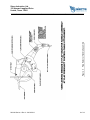
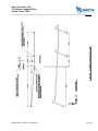
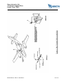
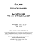
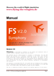
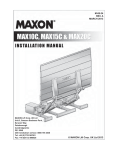
1
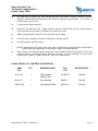
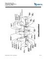
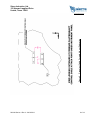
Sierra Industries, Ltd.
122 Howard Langford Drive
Uvalde, Texas 78801
___________________________________________________________________________
SERVICE BULLETIN
TITLE:
FLAP PRESELECT CONTROL CABLE - REPLACEMENT
NUMBER:
SI09-82 Series-1
EFFECTIVITY:
Cessna 414A Aircraft Modified by STC SA892NW
Cessna 402C Aircraft Modified by STC SA927NW
REV #
DATE
DESCRIPTION
APPROVED BY
IR
09/08/2010
Initial Revision
Chip King
A
06/12/2012
Minor revision to reflect ICA 82-1, Issue 1
Chip King
REASON:
To alleviate a pre-load condition on the flap drive cables when flaps are in up position.
DESCRIPTION:
This service bulletin provides parts and instructions to replace the existing flap preselect control cable
with an improved control cable, new flap preselect arm assembly and new flap speed placard to alleviate
a possible pre-load condition on the flap drive cable system when flaps are in the up position.
COMPLIANCE:
MANDATORY
APPROVAL:
FAA approval has been obtained on technical data in this publication that affects airplane type design.
SI09-82 Series-1 Rev. A 06/12/2012
Sierra Industries, Ltd.
122 Howard Langford Drive
Uvalde, Texas 78801
___________________________________________________________________________
MANPOWER:
WORK PHASE
MAN-HOURS
Installation
20
MATERIAL - Cost and Availability:
PART NUMBER
SI09-82 Series-1 Kit
AVAILABILITY
COST
Contact Sierra
Contact Sierra
TOOLING:
RIT 82-700-1 - Rigging Tool - See Figure 4 Details for Local Manufacture or See Note 1
RIT 82-700-3A - Clocking Tool - See Figure 5 Details for Local Manufacture or See Note 1
CHANGE IN WEIGHT AND BALANCE:
Negligible
REFERENCE:
Cessna 402C and 414A service documents
ICA 82-1, Issue 1 - Cessna 402C and 414A R/STOL Fowler Flap Installation Instructions for
Continued Airworthiness
Note 1 - Contact Sierra Industries, Ltd. for tool rental.
SI09-82 Series-1 Rev. A 06/12/2012
2 of 14
Sierra Industries, Ltd.
122 Howard Langford Drive
Uvalde, Texas 78801
___________________________________________________________________________
INSPECTION INSTRUCTIONS:
INSPECTION
Perform a complete inspection of the R/STOL flap system. In addition perform the following checks and
inspections. Inspections should not be limited to these items only.
1.
Check condition of flaps. Clean flaps and wing structure. Check operation of flaps for freedom of
o
o
o
o
o
o
movement and flap surface travels - Flaps 0 , Flap 10 +/- 1 , Flap 30 + 0 /-2 ; Tolerance between LH
o
and RH wing flaps 1 .
2.
Flap tracks MUST NOT be painted, and should be kept clean.
3.
Check flap track bearings for attachment, freedom of movement, and missing or damaged rollers.
4.
Thoroughly inspect all flap bellcranks and bellcrank mounting structure for damage, deformity or cracks
(removal of flap bellcranks may be required) also check flap bellcranks for attachment, and freedom
of movement.
5.
Check pushrods for attachment, freedom of movement, security. Also check rod ends for attachment
and seized bearings.
6.
Inspect nylatron side rollers (at center flap tracks) for wear. Roller wear tolerances are - OUTBD Roller
.59 min. diameter; INBD Roller .44 min. diameter.
7.
Contact Sierra Industries, Ltd. if any discrepancies are found during the inspections.
ACCOMPLISHMENT INSTRUCTIONS:
REMOVE FLAP PRESELECT CONTROL CABLE (CESSNA P/N 5115224-2)
1.
Remove necessary seats, carpet and floor panels to gain access to flap preselect control cable.
2.
Remove nut, spacer and screw attaching flap preselect control cable to flap preselect assembly at the
instrument panel, see Figure 3.
3.
Loosen nut and remove bolt and clamp from the flap extend cable and flap preselect control cable, see
Figure 6.
4.
Remove clamps securing flap preselect control cable to bulkheads and remove control cable from the
airplane and discard. Retain all hardware for reinstallation of new flap preselect control cable.
MODIFY FLAP PRESELECT CONTROL CABLE FORWARD ATTACH POINT
1.
Relocate flap preselect control cable forward attach point per Figure 2, reinstall using MS20470AD4
rivets. Remove 82-801-1 Arm Assembly from Flap Selector Handle Assembly and retain hardware. Install
82-801-2 Arm Assembly using retained hardware per Figure 3. Trim upper portion of console as required
to clear 82-801-2 Arm Assembly thru range of motion. Fill existing unused holes with MS20470AD4 rivets.
INSTALL FLAP PRESELECT CONTROL CABLE (SIERRA P/N 82-711-13)
1.
Route new flap preselect control cable in airplane and secure with retained clamps and hardware.
SI09-82 Series-1 Rev. A 06/12/2012
3 of 14
Sierra Industries, Ltd.
122 Howard Langford Drive
Uvalde, Texas 78801
___________________________________________________________________________
2.
Connect forward end of flap preselect control cable to flap preselect assembly at the instrument panel
using screw, spacer and nut retained from earlier removal see Figure 3.
3.
Do not connect flap preselect control cable to flap extend cable at this time.
RIGGING PROCEDURE
1.
The flaps must be installed and operating smoothly by hand and the flap preselect control cable should
be disconnected from the flap drive cable. The flap drive motor sprocket should be clear.
2.
Adjust the down limit switch on the flap motor (the lower switch) for maximum travel. It may be necessary
to bend the switch arm no more than the 1/10" to insure that the cam will actuate the limit switch.
NOTE: Assure that the limit switch shaft movement is properly adjusted per the Cessna 414A
service manual.
3.
Position the flap selector switch assembly at a mid travel position and the flap selector in the full DOWN
position.
4.
Turn the battery master switch on and using the flap motor circuit breaker, run the flap motor to the full
DOWN position.
5.
With flaps full DOWN (30 ):
o
1.
Disconnect flap link pushrods.
2.
Bottom flap rollers in track slots.
3.
Disconnect sprocket bellcrank pushrod at attachment to flap bellcrank.
O
6.
With the flaps in the bottom (30 position) of the tracks use the RIT 82-700-1 "Rigging Tool" to assure a
proper clocking of the flap bellcranks per Figure 4. Reconnect flap link pushrods (Both wings).
7.
Use the RIT 82-700-3A "Clocking Tool" to set the length of the 82-224-1 pushrods per Figure 5. (Both
wings).
8.
Reconnect the 82-224-1 pushrods to the 82-318-1 (-2 opp.) flap bellcranks per Figure 5. (Both Wings).
9.
Move flaps by hand to full UP and full DOWN positions. Check all moving parts for clearance,
freedom of movement and full travel.
10.
Connect the 82-711-11 flap drive cables around the flap drive motor drive sprocket and adjust direct cable
tension to 200 +/- 20 lbs. Use the RIT 82-700-3A "Clocking Tool" to check for proper clocking of the flap
drive bellcranks while bringing up cable tension, see Figure 5.
11.
Remove all rigging tools from the flap system. Making sure the flaps are clear, place the flap selector
handle in the UP position and run the flaps a few degrees UP using the flap motor circuit breaker.
12.
Place the flap selector handle in the DOWN position and using the flap motor circuit breaker run the flaps
DOWN until the limit switch on the flap motor engages.
SI09-82 Series-1 Rev. A 06/12/2012
4 of 14
Sierra Industries, Ltd.
122 Howard Langford Drive
Uvalde, Texas 78801
___________________________________________________________________________
13.
Using the RIT 82-700-3A "Clocking Tool" check the flap drive bellcranks for proper clocking. If clocking
has changed, readjust the cables per step 10.
14.
Upon obtaining a satisfactory DOWN (30 +0 /-2 ) flap position, place the flap selector handle in the UP
O
position and using the flap motor circuit breaker carefully run the flaps to the full UP position ( 0 ).
15.
Adjust the flap motor UP limit switch to turn motor off when preload on flap return cable is 250 lbs
minimum to 280 lbs. maximum.
16.
Using the flap selector handle, run the flaps DOWN and then back UP. Check the flap UP position and
readjust the flap motor UP limit switch as necessary. Repeat this step until a satisfactory flaps UP position
is obtained.
17.
Run the flaps to the full DOWN position.
18.
Adjust the flap preselect control cable sheath at the flap drive cable pulley bracket to the furthest inboard
position possible.
19.
Extend the flap preselect control cable .1" from the fully bottomed position and attach to the flap drive
cable using previously retained bolt, clamp and nuts, see Figure 6.
20.
Adjust the lower flap selector handle stop so that it stops the flap selector handle at the same time the
handle contacts the lower edge of the cutout in the instrument panel, see Figure 3.
21.
With the flap selector handle in the DOWN position, adjust the cam on the handle so that:
O
O
O
1.
The down (upper switch on the flap selector) switch assembly is still riding on the edge of the cam
but is ready to fall off the cam should the selector switch assembly move further towards the
DOWN position.
2.
Place the flap selector handle in the full UP position and run the flaps UP. It may be necessary to
adjust the flap selector handle UP stop bolt to obtain a full UP condition.
22.
Adjust the UP stop bolt so that the limit switches on the flap motor stop the flaps in the UP
position, and the UP (lower) switch roller on the flap selector switch assembly is just ready to fall off the
edge of the cam.
23.
If the flap selector handle UP stop bolt runs out of adjustment travel, the rate of the flap selector switch
assembly will have to be adjusted, see Figure 3.
24.
This is accomplished by adjusting the rod end at the forward end of the flap preselect control cable in the
slot in the 82-801-2 extension arm on the flap selector switch assembly.
25.
Moving the rod end forward in the slot (towards the long end of the arm) reduces the arc of the travel of
the selector switch assembly, requiring less travel of the handle for the same amount of flap travel,
and giving more flap travel for the same amount of handle travel.
26.
Adjust the gear warning switch so that it is not engaged in the 10
O
immediately upon selecting the 30 position.
27.
Run flaps to the full DOWN position and check direct cable tension to be 200 +/- 20 lbs.
SI09-82 Series-1 Rev. A 06/12/2012
O
position but will engage
5 of 14
Sierra Industries, Ltd.
122 Howard Langford Drive
Uvalde, Texas 78801
___________________________________________________________________________
28.
Run flaps to full UP position and check that the flap return cable tension is 250 lbs. minimum to 280 lbs.
maximum. Observe that the flap preselect control cable is not bottoming out while flaps are running to
full UP position. See Figure 6.
29.
Turn the battery master switch off.
30.
Install the new A450-129A Flap - Speed Placard in place of original A450-129 Flap - Speed Placard.
Ensure that flap indicator pointer is indicating on the placard correctly.
31.
Obtain quality department inspection of the flap drive system rigging.
32.
Check the flap drive system and flaps for installation of all safety devices.
33.
Install floor panels, carpet and seats.
NOTE: If adjustments to the rigging have been made, a maintenance test flight should be performed to
confirm proper flap rigging and to confirm that the system is operating properly.
34.
Make an entry in the airplane logbook stating this service bulletin has been accomplished. Fill out and
forward a Record of Compliance Report indicating compliance to: Sierra Industries, Ltd.,122 Howard
Langford Drive, Uvalde, TX 78801 (Questions? Toll Free: 1-888-835-9377).
SI09-82 SERIES-1 KIT - MATERIAL INFORMATION:
NEW
P/N
QTY.
82-711-13
1
82-801-2
A450-129A
OLD
P/N
INSTRUCTIONS
Flap Preselect
Control Cable
5115224-2
Discard
1
Arm Assembly
82-801-1
Discard
1
Flap-Speed Placard
A450-129
Discard
SI09-82 Series-1 Rev. A 06/12/2012
NOMENCLATURE
6 of 14
Figure 1
General Arrangement
Sierra Industries, Ltd.
122 Howard Langford Drive
Uvalde, Texas 78801
___________________________________________________________________________
SI09-82 Series-1 Rev. A 06/12/2012
7 of 14
Figure 2
Preselect Cable Forward Mount Relocation
Sierra Industries, Ltd.
122 Howard Langford Drive
Uvalde, Texas 78801
___________________________________________________________________________
SI09-82 Series-1 Rev. A 06/12/2012
8 of 14
Figure 3
Flap Selector Handle Assembly
Sierra Industries, Ltd.
122 Howard Langford Drive
Uvalde, Texas 78801
___________________________________________________________________________
SI09-82 Series-1 Rev. A 06/12/2012
9 of 14
Figure 4
Flap Bellcranks 30o Position
Sierra Industries, Ltd.
122 Howard Langford Drive
Uvalde, Texas 78801
___________________________________________________________________________
SI09-82 Series-1 Rev. A 06/12/2012
10 of 14
Figure 5 (SHT 1 OF 2) Sprocket Bellcrank Pushrod Attachment
Sierra Industries, Ltd.
122 Howard Langford Drive
Uvalde, Texas 78801
___________________________________________________________________________
SI09-82 Series-1 Rev. A 06/12/2012
11 of 14
Figure 5 (SHT 2 OF 2) Sprocket Bellcrank Pushrod Attachment
Sierra Industries, Ltd.
122 Howard Langford Drive
Uvalde, Texas 78801
___________________________________________________________________________
SI09-82 Series-1 Rev. A 06/12/2012
12 of 14
Figure 6 Flap Preselect Cable Installation
Sierra Industries, Ltd.
122 Howard Langford Drive
Uvalde, Texas 78801
___________________________________________________________________________
SI09-82 Series-1 Rev. A 06/12/2012
13 of 14
Sierra Industries, Ltd.
122 Howard Langford Drive
Uvalde, Texas 78801
___________________________________________________________________________
Record of Compliance
Please report compliance with this Service Bulletin to:
Chip King
Sierra Industries, Ltd.
122 Howard Langford Drive
Uvalde, TX 78801
Phone: (830) 278-4481
Toll Free: (888) 835-9377
Fax: (830) 278-7649
E-Mail: [email protected]
Aircraft Serial Number: _______________
Aircraft Registration Number: __________
Aircraft Total Time: __________________
Aircraft Registered Owner and Address:
________________________________
________________________________
________________________________
________________________________
Report Submitted By: ____________________________ Date: __________
Printed Name: _________________________________
SI09-82 Series-1 Rev. A 06/12/2012
14 of 14