1
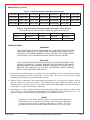
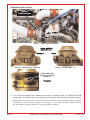
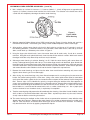
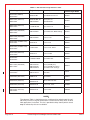
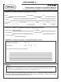
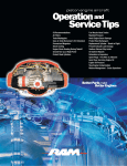
Service Bulletin
Compliance is Considered Mandatory
2900 Selma Highway
Montgomery, AL 36108 USA
Tel: 334-386-5400 Fax: 334-386-5450
Bulletin No. 040 A
Issue Date: Dec. 22, 2010
TURBOCHARGER
CHRA CONTAMINATION
REASON FOR REVISION: To revise Table 2, Cessna 421B - TSIO-520-H, should be GTSIO-520-H, added
TIO-541-E1C4 for Beech A60 Duke.
INTRODUCTION:
Hartzell Engine Technologies LLC (HET) has become aware of a condition affecting certain turbocharger
center housing rotating assemblies (CHRA) where debris may not have been removed after the machining
operation. The debris could enter the normal oil flow to the turbine wheel shaft assembly resulting in seizure
of the shaft and/or turbine wheel head separation. This condition may also lead to a loss of engine oil. Either
condition may lead to a complete loss of turbocharger function without warning as well as a partial or complete
loss of engine power. Since this debris is expected to enter the oil stream quickly, the effects listed above
can also occur quickly. The instructions herein identify the two manufacturing sources for the CHRA center
housings of which only one is affected.
This Service Bulletin is being issued to mandate the cleaning of CHRA center housing of turbochargers
according to Table 1 below.
COMPLIANCE:
For turbochargers having between 0 and 10 hours time in service (TIS) including field overhauls, before further
flight perform the IDENTIFICATION section of this procedure. If the CHRA center housing is affected,
remove the turbocharger in order to proceed to the DISASSEMBLY and CLEANING sections and perform
the required actions.
For turbochargers having between 10 and 50 hours time in service (TIS) including field overhauls: Within the
next ten (10) hours time in service, perform the IDENTIFICATION section of this procedure. If the CHRA
center housing is affected, remove the turbocharger in order to proceed to the DISASSEMBLY and CLEANING
sections and perform the required actions.
For turbochargers operated beyond 50 hours time in service, including field overhauled: No action is required.
EFFECTIVITY:
Any aircraft or engine utilizing new (-0000 series) or rebuilt (-9000 series), turbochargers, manufactured before
serial number H-NJL00003 (new) or H-NJR00002 (rebuilt) with the compliance times above. See Table 1a & 1b
for applicable part numbers
Applications may include but are not limited to those specified in Table 2.
If you have any questions concerning the instructions in this service bulletin, please contact Hartzell Engine
Technologies Technical Support at 888-461-6077.
Questions concerning aircraft service or operation must be forwarded to the applicable manufacturer of that product.
Rev. A
Hartzell Engine Technologies Service Bulletin 040
Page 1 of 9
EFFECTIVITY: (cont’d)
Table 1a - Applicable KAES Part Numbers (Turbocharger)
406990-9004
407540-0003
407540-9003
407800-9003
408590-9012
408610-0001
408610-9001
465292-0001
465292-9001
465292-0002
465292-9002
465292-0004
465292-9004
465398-0002
465398-9002
466011-0002
466011-9002
466304-0003
466304-9003
466642-0001
466642-9001
466642-0002
466642-9002
466642-0005
466642-9005
466642-0006
466642-0007
Table 1b - Applicable Original Equipment (OE) Part Numbers (Turbochargers)
The turbocharger part numbers above or below may appear on the data tag.
637374-1
633274-4
635034-2
642518-4
646677
649151-1
649151-2
46C19836
46C19839
46C22924
C295001-0301
C295001-0304
LW-10191
LW-13310
LW-16254
IDENTIFICATION
WARNING:
THIS PROCEDURE MUST BE PERFORMED BY COMPETENT AND QUALIFIED
PERSONNEL FAMILIAR WITH ENGINE AND AIRFRAME MAINTENANCE THAT IS
SPECIFIC TO THE TURBOCHARGING SYSTEM. FAILURE TO DO SO MAY RESULT
IN ECONOMIC LOSS, EQUIPMENT DAMAGE, AND/OR PHYSICAL INJURY.
CAUTION:
DO NOT DEPEND ON THIS SERVICE BULLETIN FOR GAINING ACCESS TO THE
AIRCRAFT OR ENGINE. THIS WILL REQUIRE THAT YOU USE THE APPLICABLE
MANUFACTURER’S MAINTENANCE MANUALS OR SERVICE INSTRUCTIONS. IN
ADDITION, ANY PREFLIGHT OR IN FLIGHT OPERATIONAL CHECKS REQUIRE
USE OF THE APPROPRIATE AFM OR POH.
1. Access the aircraft turbocharger(s) in accordance with the instructions in the aircraft maintenance manual.
Some aircraft engines have two turbochargers, so check both. (Do not rely on the aircraft or engine
paperwork alone to identify the turbocharger part number.)
2. Refer to Table I to determine if the turbocharger being inspected is an affected part number. Observe
the part number found on the data plate. If the affected part number does not appear, go to the
“Return to Service” section step 3 & 4. If an affected part number does appear, continue with step 3.
(See Figure 1 for typical turbocharger installation.)
3. Using Figures 2, 3, and 4, identify the foundry mark located on the CHRA center housing as shown. Those
with a circled “JT” are not affected and may proceed to the “Return to Service” section step 3 & 4. If a
“slanted A” appears, continue with the DISASSEMBLY and CLEANING sections.
NOTE:
For engine or aircraft models, reference Table 2. It should be used for identifying
turbocharged aircraft as a guide only. Not every aircraft or engine combination
is listed and not every STC or other field application is included. This list is
provided to help identify which aircraft may be affected by this service bulletin.
Page 2 of 9
Hartzell Engine Technologies Service Bulletin 040
Rev. A
IDENTIFICATION (cont’d)
Typical
Turbocharger
CHRA
Data Tag in
this Area
Figure 1 - Typical Turbo Installation
CHRA CENTER
HOUSING I.D.
Suspect
Good
Figure 2 - Foundry Mark “Slanted A”
Figure 3 - Foundry Mark “JT”
Foundry Mark May
Also Be An Indented
“Slanted A”
Suspect
4. If it has been determined that the CHRA center housing is affected per Table 1 and IDENTIFICATION
section above, the turbocharger must be removed and disassembled to isolate the CHRA center housing.
5. Utilizing the most current Service Manual or Service Instructions of the applicable engine or airframe
manufacturer, remove the turbocharger from the engine. To avoid the possibility of debris entering
the turbocharger system connections, cap all open lines and ducts.
Rev. A
Hartzell Engine Technologies Service Bulletin 040
Page 3 of 9
DISASSEMBLY AND CLEANING:
WARNING:
TO PROPERLY INSPECT, DISASSEMBLE, ASSEMBLE, AND TEST THE TURBOCHARGER, THE MOST CURRENT REVISION OF THE KELLY AEROSPACE ENERGY
SYSTEMS (KAES) OVERHAUL AND MAINTENANCE MANUAL P/N 400600-0000
MUST BE USED. THE PROCEDURES THEREIN MUST BE FOLLOWED PRECISELY.
FAILURE TO DO SO MAY RESULT IN ECONOMIC LOSS, EQUIPMENT DAMAGE,
AND/OR PHYSICAL INJURY.
NOTE:
It is required, that all turbochargers be removed from the engine and sent to HET or to
a properly FAA certificated repair station (or the foreign equivalent) experienced in
servicing turbocharger systems for this disassembly and cleaning. Removal must
be in accordance with the applicable aircraft and/or engine manufacturer’s maintenance
manuals or service instructions. Do not return turbo with fittings, oil reservoir, or
other engine or airframe parts.
1. Prepare a clean and suitable work area for the removed turbocharger. Utilizing the KAES Overhaul and
Maintenance Manual P/N 400600-0000, disassemble the turbocharger completely and isolate the CHRA.
Because of the many different models of turbochargers affected and the differences in disassembly, refer to
Table 2 to determine model. (For example, P/N 407540-9003 turbocharger would be a model T1879.) It will
be necessary to use this model number and select the instructions in Chapter 2 of the Overhaul manual P/N
400600-0000. Observe Special Tools (pages 2-410-01 & 2-420-01) for tools required for disassembly or
reassembly.
2. Using a soft bristle brush (paint brush style), thoroughly clean the outside of the CHRA prior to disassembly.
Blow dry with clean oil free shop air. This avoids outside contaminates from the CHRA affecting the
CHRA center housing cleaning process below.
3. Turn to the disassembly section of Chapter 2 and follow the appropriate steps for the specific model
turbocharger and disassemble enough to isolate the CHRA center housing from all of it’s internal
component parts (bearings, seals, wheels, etc.). Be sure to note the orientation of the housings to
one another if required by the instructions.
4. Once the CHRA center housing has been isolated, cover the remaining disassembled turbocharger parts
to avoid contamination. Proceed to CLEANING CHRA CENTER HOUSING below.
CLEANING CHRA CENTER HOUSING:
WARNING:
CLEANING MUST BE PERFORMED IN A WELL VENTILATED AREA. HAND AND EYE
PROTECTION IS REQUIRED. USE OF HAZARDOUS CHEMICALS REQUIRES A FULL
UNDERSTANDING OF EFFECTS OF HANDLING THESE PRODUCTS. FOLLOW THE
CHEMICAL MANUFACTURER’S INSTRUCTIONS FOR USE AND DISPOSAL. FAILURE
TO DO SO MAY RESULT IN PHYSICAL INJURY OR DEATH.
1. Prepare for cleaning the CHRA center housing. Obtain the following materials locally:
Two clean solvent and corrosive resistant metal buckets 1.5 gal. minimum (5.7 liter).
A Large Flexible Nylon Bristle Brush (.50 inch diameter) min.1 in. long brush. SHB P/N 1303 or equivalent*
A Small Flexible Nylon Bristle Brush (.25 inch diameter) min.1 in. long brush. SHB P/N 1307 or equivalent*
Super Strength Greased Lightning Multi-Purpose Degreaser or equivalent, sufficient amount.
One graduated beaker 150 ml (five ounce).
Oil Preservative, Castrol 4130GA, 4135 at 100% or Turco 4454 diluted 90% with water (or equivalent).
Solvent resistant rubber gloves.
* Solo Horton Brushes, Inc, P.O. Box 478, Winsted, CT 06098 (http://www.solobrushes.com)
Page 4 of 9
Hartzell Engine Technologies Service Bulletin 040
Rev. A
CLEANING CHRA CENTER HOUSING: (cont’d)
2. Mix a solution at a ratio of 3.4 ounces +/- 1/3 ounce (100 ml +/- 10 ml) of Degreaser to approximately
4 quarts (3.79 liters) of warm water into the first clean bucket. The solution in the bucket must be at
a level that will completely submerge the entire center housing.
Figure 4
Typical CHRA
Center Housing
3. Wearing protective Rubber Gloves, place CHRA center housing (Figure 4) into the bucket and soak for a
minimum of 30 seconds. If the housing has coking or other stubborn deposits, allow to soak longer.
4. After soaking, agitate center housing by hand in the bucket for a minimum of 15 seconds in each of
the following directions: Center bore vertical, cold side down, center bore vertical, cold side up, oil drain
down, and oil drain up. Reference points shown in Figure 4.
5. Using the large nylon bristle brush, insert into center bore and oil outlet cavity. Scrub for 3 seconds
minimum. Using the small nylon bristle brush, insert into the oil inlet and drain cavities. Work brush around
the edges inside the cavity where chips and burrs may be located.
6. Submerge center housing in solution allowing it to fill. Hold the center housing with center bore axis
vertical, submerge housing with cold side up. Place index finger over the oil feed hole, place thumb over
the oil drain hole, place middle finger of the other hand over the hot side center bore, and thumb over the
cold side center bore. Raise part from bucket and shake for 5 seconds minimum. Orient oil drain port down
and remove thumb to allow solution to drain into the bucket. Repeat this step two times.
7. Remove the center housings and place into the other clean metal bucket containing only warm water.
Agitate center housing and rinse thoroughly.
8. After rinsing, dry center housings using clean filtered compressed air assuring that all water enters the
bucket. Set center housing aside in a clean area. Using a new conical paint strainer (filter) or some other
easily seen filter media, agitate the first and second buckets and pour the the contents of each through the
filter. Ferrous chips can be identified by passing a magnet along the outside of the filter opposite its
screen area and observing the response of any captured particles. Observe filter and the bottom of each
bucket and record findings on Attachment A at the end of this service bulletin. It is normal to see some
level of debris as a result of outside contaminant's such as carbon, Loctite chips, etc. Use of paper paint
strainer obtained at local hardware store (or equivalent) is acceptable.
9. Treat the center housing with preservative oil immediately after cleaning. Use either Castrol 4130GA, Castrol
4135 at 100% or Turco 4454 diluted 90% with water. Other equivalent products may be used, however,
closely observe dilution and mixing instructions.
10. The center housing has multiple cavities inside and out so preservative treatment is more effective when
dipped rather than sprayed. Submerge the center housing in a solution of preservative oil as called out in
step 16. Pour out excess and rotate center housing to assure all excess oil is removed. The housing
may then be dried in still air or by applying compressed shop air.
Rev. A
Hartzell Engine Technologies Service Bulletin 040
Page 5 of 9
REASSEMBLY:
1. Once the CHRA center housing has been cleaned, reassemble the turbocharger. Observe Chapter 2
General Cleaning instructions (pages 2-230-01 & 2-240-01) and General Inspection (pages 2-250-01 &
2-400-01) as required prior to starting reassembly.
2. Reassemble the turbocharger referring to the appropriate Reassembly section of Chapter 2 for your
specific model designation. Be sure to return the housings to the proper orientation as noted if previously
required by the instructions.
REPAIRED TURBOCHARGER INSTALLATION:
1. Upon completion of the turbocharger reassembly, the appropriate paperwork must be made indicating that
the turbocharger has been repaired. This paperwork must be included in the aircraft records. Once this
is accomplished, prepare to re-install the turbocharger on the engine. If sent to a repair station, verify
the turbocharger has the correct part number and serial number for your aircraft and that the proper
paperwork was delivered with the unit.
2. Prior to installation of the turbocharger, flush the oil line from the turbo to the oil sump with clean engine
oil. Utilizing the most current Service Manual or Service Instructions of the applicable engine or airframe
manufacturer, perform an engine oil and filter change. Drain the engine oil completely through a porous
white cloth to examine for metal particles and ferrous chips. Remove the engine oil filter and completely
drain contents through a porous white cloth and examine for metal particles and ferrous chips.
3. Cut open the oil filter and examine the pleats for metal particles and ferrous chips. If a magnetic oil plug
is installed, examine it for metal particles and ferrous chips.
4. If metal particles and ferrous chips are present, consult the engine manufacturer’s recommendations for
engine oil contamination and/or oil system flushing prior to completing engine oil and filter change. If no
metal particles or ferrous chips are found or upon completion of the above actions, complete the engine oil
and filter change per engine manufacturer’s service instructions.
5. Utilizing the applicable aircraft and/or engine manufacturer’s maintenance manuals or service instructions
of the latest revision, re-install the turbocharger assembly and proceed to “Return to Service” below.
RETURN TO SERVICE:
1. Once the turbocharger has been properly re-installed, the aircraft will be ready for return to service.
2.
Refer to Kelly Aerospace Energy Systems Service Bulletin 23 and perform the recommended turbocharger
operational tests. This consists of turbocharger pre-lubrication, ground running tests, and and operational flight
test. Make sure no air, exhaust, or oil leaks are present. Service Bulletin may be viewed or downloaded online
via http://www.HartzellEngineTechnologies.com.
3.
Utilizing the applicable aircraft and engine manufacturer’s maintenance manuals of the latest revision,
install any portion of the aircraft removed to gain access.
4.
Upon successful completion of this service bulletin per the applicable compliance time listed, make an
appropriate log book entry. (If repair accomplished, be sure to include the turbo repair records).
Page 6 of 9
Hartzell Engine Technologies Service Bulletin 040
Rev. A
PARTS REQUIRED:
Consult the latest revision of the KAES Turbocharger Overhaul & Maintenance manual (P/N 400600-0000)
Illustrated Parts Catalog as required to comply with this service bulletin. Incidental parts may be required for
the turbocharger installation. These parts must be obtained from the applicable engine or airframe manufacturer.
PARTS IN INVENTORY:
Affected unused stock in customers hands must be returned through place of purchase.
See the Appendix I for Commercial Assistance.
Rev. A
Hartzell Engine Technologies Service Bulletin 040
Page 7 of 9
TABLE 2 - Affected Turbocharger Reference Table
Turbocharger Ass’y
Engine Ass’y
Aircraft (not limited to)
Turbocharger Model
466304-0003 (646677)
466304-9003
TSIO-520-BE
Piper Malibu Conversion
TA3601
466642-0001 (649151-1)
466642-9001
TSIO-360-MB, SB
TIO-540-AK1A
Mooney Encore
TIO-540-AK1AT
TA3601
466642-0002 (649151-2)
466642-9002
L/TSIO-360-RB
Piper, Seneca V
TA3601
466642-0005 (46C19839)
466642-9005
TIO-540-AE2A
Piper PA46-350P, Malibu Mirage
TA3601
466642-0006 (46C22924)
466642-9006
TIO-540-AK1A
Cessna, T182
TAO411
465292-0001 (C295001-0301)
465292-9001
TSIO-360-H
Cessna T337
TAO401
465292-0002 (C295001-0304)
465292-9002
0-540-L3C5D
Cessna T182, TR182
TAO401
465292-0004 (642518-4)
465292-9004
TSIO-520-T
Cessna T188C
TAO401
465398-0002
465398-9002
L/TO-360-E1A6D
Piper PA44-180T
TAO402
466011-0002 (46C19836)
466011-9002
TIO-540-AG1A
TIO-540-AF1A
TIO-540-AF1B
TIO-540-AH1A
Commander 114TC
Mooney M20M (TLS)
Mooney M20M (TLS Bravo)
Piper PA32-301T Saratoga
TAO413
407540-0003 (LW-13310)
407540-9003
TIO-541-E1D4
TIO-541-E1C4
Beech A56TC,
A60, Duke
T1879
407800-9003 (LW-10191)
TIGO-541-E
Piper PA31P
T18A21
408590-9012 (635034-2)
GTSIO-520-F,
GTSIO-520-K
Twin Commander 685
T18A44
406990-9004 (633274-4)
GTSIO-520-D
Cessna 421, 421A
THO867
408610-0001 (632729-1)
408610-9001
GTSIO-520-H
Cessna 421B
TEO659
NOTE::
The reference Table 2 should be used as a guide only for turbocharged aircraft.
Not every aircraft or engine combination is listed and not every STC or other
field application is included. This list is provided to help identify which aircraft
may be affected by this service bulletin.
Page 8 of 9
Hartzell Engine Technologies Service Bulletin 040
Rev. A
APPENDIX I
COMMERCIAL ASSISTANCE:
In addition to warranty coverage provided by the KAES or HET Limited Warranty, HET will provide
additional commercial assistance to comply with SB040 under the terms outlined in this Appendix.
Commercial Assistance – the following will be provided with the submission of a completed PPCR
(Attachment A, Sections I and II only) along with copies of invoices showing breakdown of labor
charges and log book entries. This will serve as a claim form when received by HET warranty department.
If the unit is not sent to HET for disassembly and cleaning, a completed PPCR (Attachment A, with all
Sections completed) along with copies of invoices showing breakdown of labor charges and log book
entries must be submitted. This will serve as a claim form when received by HET warranty department.
Identification – up to 1 hour labor (up to $75 maximum)
Removal and Installation, if necessary – up to 4 hours labor (up to $300 maximum)
Disassembly and Cleaning – Reassembly
Within North America - for units sent to HET there will be no charge for this work and unit will be
returned shipping pre-paid by the same method as received.
Outside North America – for units sent to HET there will be no charge for this work and will be
returned shipping pre-paid, less any applicable duties, by the same method as received. As an
alternative, HET will provide a labor allowance of 3 hours labor (up to US $225 maximum) for units
sent to nearest of the following facilities:
PLANE SUPPORT (AEROTEST PTY LTD)
Sunshine Coast Airport
Mudjimba Qld 4564 Australia
ABN 12 079 212 981 E-mail: [email protected]
Ph: 61 7 5448 9824 Fax: 61 7 5448 9287
ROEDER PRAEZISION
Am Flugplatz
Egelsbach
63329, Germany
Tel: +49 6103 4002 0 Fax: +49 6103 4002 700
URL: www.roeder-praezision.com
VORTEX MOTORS
Aj. Olavo Fontoura 484
San Paulo Brazil 02012-020
Tel: 55 11 6221 8566
Fax: 55 11 6251 0406
E-mail: [email protected]
E-mail: [email protected]
SHIPPING INFORMATION: (when returning to HET)
Turbocharger must be securely packed and packaged so no oil will seep into the shipping container. A copy
of “Attachment A” must have “Customer Information” and “Product or Component Information” sections filled
out completely and included inside the shipping container. The turbocharger must be received assembled and
undamaged to qualify for repair. Address package to Hartzell Engine Technologies, LLC, Warranty
Department, 2900 Selma Highway, Montgomery, AL 36108, USA. Also mark “WARRANTY DEPT” clearly on
the outside of the shipping container. HET will only pay for return shipping by the same method as
received. (next day, ground, etc.)
CONTACT INFORMATION:
All communications regarding this service bulletin, must be placed either through Hartzell Engine Technologies
Technical Support at (888) 461-6077 or via Fax (334) 386-5450. For the Warranty department, (334) 386-5441.
Written communications must be placed through Hartzell Engine Technologies Technical Support, 2900 Selma
Highway, Montgomery, AL 36108, USA.
If E-mail communication is desired, go to our website: http://www.HartzellEngineTechnologies.com and select
“contact”and follow the instructions.
Rev. A
Hartzell Engine Technologies Service Bulletin 040
Page 9 of 9
ATTACHMENT A
PPCR
Publication Product Condition Report
(To validate warranty or commercial assistance, all information MUST be filled out.)
SECTION I: Customer information (Completed by End User)
Name:
Date of Report:
Tel:
Company Name:
E-mail:
Address:
Aircraft Mfg/:
Engine
Time in Service:
Model:
S/N:
(as may be applicable)
SECTION II: Product or Component Information (Completed by End User)
Nomenclature: TURBOCHARGER
Part Number:
Serial Number:
Batch/Date Code:
Part Time in Service:
SECTION III: Compliance Information: (Completed by Repair Facility)
Compliance with SB-040:
YES
o
Debris found:
YES
o
NO
o
If yes, please describe quantity and size below:
Eligibility:
To be eligible for any commercial assistance, this form must be completed as instructed above and will serve as a
claim form. NO reimbursement will be made without completing this form.
For further information contact Hartzell Engine Technologies, LLC at: 2900 Selma Highway, Montgomery, AL,
USA or FAX to HET Customer Service, 334-386-5450. The complete service bulletin is available to you online via
our website at http://www.HartzellEngineTechnologies.com.