1
OB397--1.qxp
05.3.18 2:12 PM
Page 1
SPLIT-TYPE, AIR CONDITIONERS
No. OB397
SERVICE MANUAL
Wireless type
Models
MU-A08VDMU-A10VDMU-A13VD-
P1
P1
P1
CONTENTS
Indication of
model name
MU-A08VD MU-A10VD MU-A13VD -
P1
P1
P1
1. TECHNICAL CHANGES ····································2
2. PART NAMES AND FUNCTIONS······················2
3. SPECIFICATION·················································3
4. OUTLINES AND DIMENSIONS ·························4
5. WIRING DIAGRAM ············································4
6. REFRIGERANT SYSTEM DIAGRAM ················5
7. PERFORMANCE CURVES ································6
8. TROUBLESHOOTING········································8
9. DISASSEMBLY INSTRUCTIONS·····················11
10. PARTS LIST······················································16
11. OPTIONAL PARTS ···········································18
TM
NOTE:
• This service manual describes technical data of outdoor units.
• As for indoor units MS-A08VD - P1 ,MS-A10VD - P1 and MS-A13VD -
P1
, refer to the service manual OB396.
OB397--1.qxp
1
05.3.18 2:12 PM
Page 2
TECHNICAL CHANGES
MU-07UV - P1 ➔ MU-A08VD - P1
1. Outdoor unit model has been changed.
•Dimension has been changed. (780Wo540Ho255D ➔ 800Wo550Ho285D)
•Valve bed has been added.
2. Compressor has been changed. (RH135VGCC ➔ RH135VHCC)
3. Outdoor fan motor has been changed. (RA6V23-HA ➔ RA6V21-AC)
4. Outdoor fan motor capacitor has been changed.
5. Compressor capacitor has been changed.
MU-10UV - P1 ➔ MU-A10VD - P1
1. Outdoor unit model has been changed.
•Dimension has been changed. (780Wo540Ho255D ➔ 800Wo550Ho285D)
•Valve bed has been added.
2. Compressor has been changed. (RH165VGCC ➔ RH145VHCC)
3. Outdoor fan motor has been changed. (RA6V23-HA ➔ RA6V21-AC)
4. Outdoor fan motor capacitor has been changed.
5. Compressor capacitor has been changed.
MU-13UV - P1 ➔ MU-A13VD - P1
1. Outdoor unit model has been changed.
•Dimension has been changed. (780Wo540Ho255D ➔ 800Wo550Ho285D)
•Valve bed has been added.
2. Compressor has been changed. (RH231VHAC ➔ RH207VHAC)
3. Outdoor fan motor has been changed. (RA6V33-FA ➔ RA6V33-KA)
4. Outdoor fan motor capacitor has been changed.
5. Compressor capacitor has been changed.
2
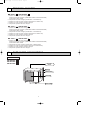
PART NAMES AND FUNCTIONS
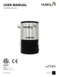
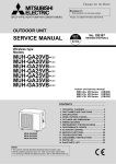
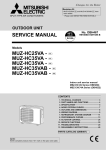
OUTDOOR UNIT
MU-A08VD - P1
MU-A10VD - P1
MU-A13VD - P1
Air inlet
(back )
Piping
Drain hose
Air outlet
Drain outlet
2
OB397--1.qxp
05.3.18 2:12 PM
3
Page 3
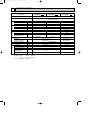
SPECIFICATION
Outdoor model
MU-A08VD -
Function
Electrical
Capacity
data
Power supply
Special
remarks
Fan
motor
Compressor
Capacity
kW
Dehumidification
R/h
Air flow
K /h
Starting current
A
Compressor motor current
A
Fan motor current
A
Coefficient of performance (C.O.P)
Model
Output
W
Winding
"
resistance (at20:)
Model
Winding
"
resistance (at20:)
Dimensions WOHOD
mm
Weight
kg
Sound level
dB
Fan speed
rpm
Fan speed regulator
Refrigerant filling
kg
capacity (R22)
Refrigeration oil (Model)
cc
MU-A10VD -
P1
P1
Cooling
Single phase
220-230-240V, 50Hz
2.3-2.3-2.3
2.75-2.75-2.75
1.0
1.2
1740-1800-1860
17-18-19
18-19-20
2.85-2.85-2.84
3.22-3.22-3.21
0.24-0.25-0.25
3.24-3.24-3.24
3.46-3.46-3.46
RH135VHCC
RH145VHCC
650
700
C-R 4.18
C-R 4.03
C-S 5.76
C-S 5.71
RA6V21-AC
WHT-BLK 347
BLK-RED 281
800o550o285
31
44-45-46
725-745-770
1
NOTE: Test conditions are based on JIS C 9612.
Cooling : Indoor
DB27°C / WB19°C
Outdoor
DB35°C / WB24°C
Indoor-Outdoor piping length 5 m
3
MU-A13VD -
P1
3.7-3.7-3.7
1.7
1848-1872-1896
28-29.5-31
4.53-4.52-4.51
0.33-0.34-0.35
3.36-3.36-3.36
RH207VHAC
1000
C-R 2.59
C-S 3.94
RA6V33-KA
WHT-BLK 215
BLK-RED 307
36
47-47-48
835-845-855
0.55
1.05
300 (MS56)
520 (MS56)
OB397--1.qxp
Page 4
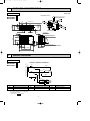
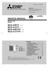
OUTLINES AND DIMENSIONS
Unit : mm
OUTDOOR UNIT
MU-A08VD - P1
MU-A10VD - P1
MU-A13VD - P1
REQUIRED SPACE
ore
mm
100
100
mm
Drain hole [42
or m
or m
Bolt pitch for
installation
304~325
ore
44
Air in
40
2 holes 10X21
ore
350
mm
rm
mo
2
or m
ore
00m
Open two sides of left,
right, or rear side.
17.5
285
400
Air in
344.5
Basically open 100mm or more
without any obstruction in front
and on both sides of the unit.
Service panel
Air out
23
22.3
Liquid refrigerant pipe joint
Refrigerant pipe (flared) [6.35
150
69
99.5
10
164.5
280
35-
550
Handle
43-
4
05.3.18 2:12 PM
302.5
170.5
Service port
Gas refrigerant pipe joint
Refrigerant pipe (flared) [9.52 (MU-A08/A10VD)
Refrigerant pipe (flared) [12.7 (MU-A13VD)
500 Bolt pitch for installation
800
WIRING DIAGRAM
OUTDOOR UNIT
MU-A08VD - P1
MU-A10VD - P1
MU-A13VD - P1
TB
WHT
2
BLU
C1
C
RED S
R
WHT
BLK
C2
RED
3
BLK
2
WHT
WHT
1
SYMBOL
NAME
MC
N
BLU
TO INDDOR UNIT CONNECTING
MODEL WIRING DIAGRAM
220-230-240V~
5
RED
MF
SYMBOL
NAME
C1
COMPRESSOR CAPACITOR
MC
COMPRESSOR (INNER PROTECTOR)
C2
OUTDOOR FAN CAPACITOR
MF
OUTDOOR FAN MOTOR (INNER FUSE)
NOTE:1. About the indoor side electric wiring refer to the indoor unit electric wiring diagram for servicing.
2. Use copper conductors only. (For field wiring)
3. Symbols below indicate.
/: Terminal block,
: Connector
4
SYMBOL
TB
NAME
TERMINAL BLOCK
OB397--1.qxp
05.3.18 2:12 PM
6
Page 5
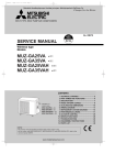
REFRIGERANT SYSTEM DIAGRAM
Unit : mm
MU-A08VD MU-A10VD - P1
OUTDOOR UNIT
P1
Refrigerant pipe
(Option){9.52
(with heat insulator)
Stop valve
(with service port)
Outdoor
heat
exchanger
Flared
connection
Compressor
Strainer
#100
Flared
connection
Stop valve Capillary tube
{3.0 x { 1.6 x 850
Refrigerant pipe
(Option){6.35
(with heat insulator)
Refrigerant flow in cooling
MU-A13VD - P1
OUTDOOR UNIT
Refrigerant pipe
Stop valve
(Option){12.7
(with heat insulator) (with service port)
Outdoor heat
exchanger
Flared
connection
Compressor
Strainer
#100
Flared
connection
Stop valve
Capillary tube
{3.0 x {1.6x650
Refrigerant pipe
(Option){6.35
(with heat insulator)
Refrigerant flow in cooling
5
OB397--1.qxp
05.3.18 2:12 PM
Page 6
MAX.REFRIGERANT PIPING LENGTH
Refrigerant piping : m
Model
Max. length Max. height
Piping size O.D : mm
A
B
Gas
MU-A08VD MU-A10VD -
P1
P1
20
10
{9.52
MU-A13VD -
P1
20
10
{12.7
Liquid
{6.35
MAX.HEIGHT DIFFERENCE
Indoor
unit
w Max. Height
B
Refrigerant Piping
Max. Length
A
Outdoor unit
ADDITIONAL REFRIGERANT CHARGE(R22 : g)
Outdoor unit precharged
Model
MU-A08VD MU-A10VD -
P1
P1
MU-A13VD -
P1
Refrigerant piping length (one way)
7m
10m
15m
20m
550
0
45
120
195
1050
0
45
120
195
NOTE : Calculation : Xg=15g/m ✕ (Refrigerant piping length (m)-7)
7
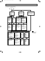
PERFORMANCE CURVES
MU-A08VD - P1
MU-A10VD - P1
MU-A13VD - P1
The standard data contained in these specifications apply only to the operation of the air conditioner under normal conditions.
Since operating conditions vary according to the areas where these units are installed. The following information has been
provided to clarify the operating characteristics of the air conditioner under the conditions indicated by the performance curve.
(1) GUARANTEED VOLTAGE
198 ~ 264V, 50Hz
(2) AIR FLOW
Air flow should be set at MAX.
(3) MAIN READINGS
(1) Indoor intake air wet-bulb temperature :
°CWB
(2) Indoor outlet air wet-bulb temperature :
°CWB
(3) Outdoor intake air dry-bulb temperature : °CDB
(4) Total input:
W
Indoor air wet/dry-bulb temperature difference on the left side of the chart on next page shows the difference between the
indoor intake air wet/dry-bulb temperature and the indoor outlet air wet/dry-bulb temperature for your reference at service.
6
OB397--1.qxp
05.3.18 2:12 PM
Page 7
How to measure the indoor air wet/dry-bulb temperature difference
1.
2.
3.
4.
5.
6.
7.
Attach at least 2 sets of wet and-dry-bulb thermometers to the indoor air intake as shown in the figure, and at least 2 sets
of wet and dry-bulb thermometers to the indoor air outlet. The thermometers must be attached to the position where air
speed is high.
Attach at least 2 sets of wet and dry-bulb thermometers to the outdoor air intake.
Cover the thermometers to prevent direct rays of the sun.
Check that the air filter is cleaned.
Open windows and doors of the room.
Press the EMERGENCY OPERATION switch once to start the EMERGENCY COOL MODE.
When system stabilizes after more than 15 minutes, measure temperature and take an average temperature.
10 minutes later, measure temperature again and check that the temperature does not change.
INDOOR UNIT
OUTDOOR UNIT
Wet-and dry-bulb
thermometers
Wet and dry-bulb
thermometers
7.0
11.2
Indoor intake air WB temperature (:)
6.5 10.2
5.4
8.4
4.8
7.5
4.3
6.7
MS-A13VD - P1
MU-A13VD - P1
9.3
MS-A08VD - P1
MU-A08VD - P1
MS-A10VD - P1
MU-A10VD - P1
5.9
Indoor intake air WB temperature (:)
Outdoor intake air DB temperature (:)
Outdoor intake air DB temperature (:)
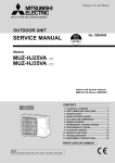
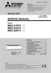
OUTDOOR LOW PRESSURE AND OUTDOOR UNIT CURRENT
COOL operation
1 Both indoor and outdoor units are under the same temperature/humidity condition.
Dry-bulb temperature (:)
Relative humidity (%)
20
50
25
60
30
70
2 Air flow should be set at MAX.
3 The unit of pressure has been changed to MPa on the international system of units(SI unit system).
f [Gauge])
The conversion factor is : 1(MPa [Gauge]) =10.2(kgf/f
7
OB397--1.qxp
05.3.18 2:12 PM
Page 8
(kgf/F [Gauge])(MPa [Gauge])
8.0
7.0
6.0
5.0
4.0
MU-A08VD - P1
MU-A10VD - P1
4.0
0.9
220V
0.8
Outdoor unit current (A)
Outdoor low pressure
9.0
MU-A08VD - P1
MU-A10VD - P1
0.7
0.6
0.5
0.4
15
20
50
25
60
30
70
(kgf/F [Gauge])(MPa [Gauge])
7.0
220V
3.0
2.5
2.0
15
35(:)
(%)
Ambient temperature (˚C)/Ambient humidity (%)
3.5
20
50
25
60
30
70
Ambient temperature (˚C)/Ambient humidity (%)
MU-A13VD - P1
MU-A13VD - P1
6
0.7
5.0
4.0
3.0
220V
Outdoor unit current (A)
Outdoor low pressure
220V
6.0
0.6
0.5
0.4
0.3
15
20
50
25
60
30
70
35(:)
(%)
Ambient temperature (˚C)/Ambient humidity (%)
8
35(:)
(%)
5
4
3
15
20
50
25
60
30
70
35(:)
(%)
Ambient temperature (˚C)/Ambient humidity (%)
TROUBLESHOOTING
MU-A08VD - P1
MU-A10VD - P1
MU-A13VD - P1
8-1. Cautions on troubleshooting
1. Before troubleshooting, check the following:
1) Check the power supply voltage.
2) Check the indoor/outdoor connecting wire for mis-wiring.
2. Take care the following during servicing.
1).Before servicing the air conditioner, be sure to turn off the main unit first with the remote controller, and then after confirming the horizontal vane is closed, turn off the breaker and / or disconnect the power plug.
2) Be sure to turn OFF the power supply before removing the front panel,
the cabinet, the top panel and the electronic control P.C. board.
3) When removing the electronic control P.C. board, hold the edge of the
board with care NOT to apply stress on the components.
4) When connecting or disconnecting the connectors, hold the housing of the
connector. DO NOT pull the lead wires.
Lead wiring
8
Housing point
OB397--1.qxp
05.3.18 2:12 PM
Page 9
8-2. Instruction of troubleshooting
Start
Indoor unit
operates.
Outdoor unit
doesn't
operate.
Outdoor unit
operates in
only Test Run
operation.
Check room
temperature
thermistor.
Refer to
"Test point
diagram and
voltage".
Indoor unit
doesn't receive
the signal from
remote controller.
OPERATION INDICATOR
lamp on the indoor unit is
flashing on and off.
Outdoor unit
doesn't
operate
even in
Test Run
operation.
Indoor unit
operates, when
the EMERGENCY
OPERATION
switch is pressed.
Indoor unit
doesn't operate,
when the
EMERGENCY
OPERATION
switch is pressed.
Check of 5.
wiring
diagram
of outdoor
unit.
Refer to
"Check of
remote controller
and receiver
P.C. board".
1. Check indoor /
outdoor
connecting wire.
2. Refer to
"Check of indoor
electronic control
P.C. board".
Both lamps
(Left and right)
Flash on and off at
0.5-second intervals
Cause:
Indoor unit
• The horizontal vanes
are not installed
correctly.
Refer to "Check of
installation of the
horizontal vane".
Left lamp
2-time flash
Cause:
Indoor unit
• Trouble of room
temperature/
indoor coil
thermistor
Check room
temperature
thermistor and
indoor coil thermistor.
Refer to
"Test point diagram
and voltage".
Left lamp
3-time flash
Cause:
Indoor unit
• Trouble of
indoor fan
motor
Refer to
"Check of
indoor fan
motor".
9
Left lamp
4-time flash
Cause:
Indoor unit
• Trouble of
indoor control
system
Replace the
indoor
electronic
control P.C.
board.
As for indoor unit,
refer to service
manual OB396.
OB397--1.qxp
05.3.18 2:12 PM
Page 10
8-3. Trouble criterion of main parts
MU-A08VD - P1
MU-A10VD - P1
MU-A13VD - P1
Check method and criterion
Part name
Measure the resistance between the terminals with a tester.
(Coil wiring temperature -10°C ~ 40°C)
Compressor
(MC)
INNER
PROTECTOR
MU-A08/A10VD
150i 5: OPEN
90i10: CLOSE
MU-A13VD
155i 5: OPEN
90i10: CLOSE
Outdoor fan
motor (MF)
Figure
Color of
lead wire
WHT
Normal
MU-A10VD
MU-A08VD
MU-A13VD
C-R
3.0 ~ 4.51 "
3.0 ~ 4.35 "
2.0 ~ 2.8 "
C-S
5.0 ~ 6.22 "
5.0 ~ 6.16 "
3.0 ~ 4.25 "
C
Abnormal
Open or
short-circuit
P
S
R BLK
RED
Measure the resistance between the terminals with a tester.
(Coil wiring temperature -10°C ~ 40°C)
MAIN
Normal
AUX.
INNER FUSE
Color of
lead wire
MU-A08/A10VD
MU-A13VD
149i 3: OPEN
WHT-BLK
305 ~ 374 "
189 ~ 233 "
BLK-RED
247 ~ 304 "
270 ~ 332 "
Abnormal
Open or
short-circuit
FUSE
BLK
RED WHT
P:INNER PROTECTOR
10
OB397--1.qxp
05.3.18 2:12 PM
9
Page 11
DISASSEMBLY INSTRUCTIONS
<"Terminal with locking mechanism" Detaching points>
The terminal which has the locking mechanism can be detached as shown below.
There are two types ( Refer to (1) and (2)) of the terminal with locking mechanism.
The terminal without locking mechanism can be detached by pulling it out.
Check the shape of the terminal before detaching.
(1) Slide the sleeve and check if there is a locking lever or not.
(2) The terminal with this connector has the locking
mechanism.
Sleeve
Locking lever
9-1.
1Slide the sleeve.
2Pull the terminal while
pushing the locking
lever.
1Hold the sleeve, and
pull out the terminal
slowly.
Connector
MU-A08VD - P1 MU-A10VD - P1
OUTDOOR UNIT
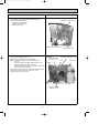
OPERATING PROCEDURE
PHOTOS
1. Removing the cabinet
(1) Remove the screws fixing the top panel. (See Photo 2 and
3.)
(2) Remove the top panel. (See Photo 3.)
(3) Remove the screw fixing the service panel. (See Photo 3.)
(4) Pull down the service panel and remove it. (See Photo 3.)
(5) Remove the screws fixing the cabinet.
(6) Remove the cabinet.
(7) Disconnect the indoor/outdoor connecting wire.
(8) Remove the screws fixing the back panel.
(9) Remove the back panel.
Photo 3
Photo 1
Screws of the front panel and motor support
Screws of the cabinet
Screws of the
top panel
Photo 2
Service
panel
Screw of the
service panel
Direction
to remove
Hooks
Screw of the
cabinet
11
Screws of
the top panel
Screws of
the cabinet
OB397--1.qxp
05.3.18 2:12 PM
Page 12
OPERATING PROCEDURE
PHOTOS
2. Removing the electrical parts
(1) Remove the service panel and the cabinet.(Refer to 1.)
(2) Remove the following parts.
•Compressor capacitor (C1)
•Outdoor fan capacitor (C2)
•Terminal block (TB)
Photo 4
Compressor capacitor (C1)
Outdoor fan capacitor (C2)
Terminal block(TB)
3. Removing the propeller and the outdoor fan motor
(1) Remove the cabinet. (Refer to 1.)
(2) Remove the propeller nut and the propeller.
NOTE : Loose the propeller in the rotating direction for
removal.
When attaching the propeller, align the mark on the
propeller and the motor shaft cut section.
Set the propeller in position by using the cut on the shaft
and the mark on the propeller.
(3) Remove the lead clamps and outdoor fan motor lead wires.
(4) Remove the screws fixing the outdoor fan motor.
(5) Remove the outdoor fan motor.
Photo 5
Set screws of the
outdoor fan motor
Hook
Propeller
Propeller
nut
Set screws of the
outdoor fan motor
12
Outdoor fan motor lead wires
Outdoor
fan motor
Relay panel
OB397--1.qxp
05.3.18 2:12 PM
Page 13
OPERATING PROCEDURE
PHOTOS
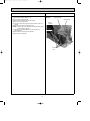
4. Removing the compressor
(1) Remove the cabinet. (Refer to 1.)
(2) Remove the soundproof felt.
(3) Remove the screws fixing the relay panel.
(4) Remove the terminal cover.
(5) Pull out the lead wires from the glass terminal of the compressor.
(6) Recover gas from the refrigerant circuit.
NOTE : Recover gas from the pipes until the pressure gauge
shows 0 kg/cm2 (0MPa).
(7) Disconnect the welded part of the suction pipe and
discharge pipe.
(8) Remove the nuts fixing the compressor.
(9) Remove the compressor.
Photo 6
Discharge pipe
Suction pipe
Glass
terminal
Compressor
Compressor
nuts
13
OB397--1.qxp
9-2.
05.3.18 2:12 PM
Page 14
MU-A13VD - P1
OUTDOOR UNIT
OPERATING PROCEDURE
PHOTOS
1. Removing the cabinet
(1) Remove the screws fixing the top panel. (See Photo 2 and
3.)
(2) Remove the top panel. (See Photo 3.)
(3) Remove the screw fixing the service panel. (See Photo 3.)
(4) Pull down the service panel and remove it. (See Photo 3.)
(5) Remove the screws fixing the cabinet.
(6) Remove the cabinet.
(7) Disconnect the indoor/outdoor connecting wire.
(8) Remove the screws fixing the back panel.
(9) Remove the back panel.
Photo 1
Screws of the front panel and motor support
Screws of the cabinet
Photo 3
Screws of the
top panel
Photo 2
Service
panel
Screws of
the top panel
Screw of the
service panel
Direction
to remove
Screws of
the cabinet
Hooks
Screw of the
cabinet
2. Removing the electrical parts
(1) Remove the service panel and the cabinet. (Refer to 1.)
(2) Remove the following parts.
•Compressor capacitor (C1)
•Outdoor fan capacitor (C2)
•Terminal block (TB)
Photo 4
Connector
Compressor
capacitor (C1)
Outdoor
fan
capacitor
(C2)
Terminal
block (TB)
14
OB397--1.qxp
05.3.18 2:12 PM
Page 15
OPERATING PROCEDURE
PHOTOS
3. Removing propeller and the outdoor fan motor
(1) Remove the cabinet. (Refer to 1)
(2) Remove the propeller nut and remove the propeller.
NOTE : Loose the propeller in the rotating direction for
removal.
When attaching the propeller, align the mark on the
propeller and the motor shaft cut section.
Set the propeller in position by using the cut on the
shaft and the mark on the propeller.
(3) Disconnect the connector and remove the lead clamps and
outdoor fan motor lead wires.
(4) Remove the screws fixing the outdoor fan motor.
(5) Remove the outdoor fan motor.
Photo 5
Outdoor fan motor lead wires
Set screws of the
outdoor fan motor
Hook
Relay panel
Propeller
Outdoor
fan motor
Propeller
nut
Set screws of the
outdoor fan motor
4. Removing the compressor
(1) Remove the cabinet. (Refer to 1)
(2) Remove the relay panel.
(3) Remove the soundproof felt.
(4) Remove the terminal cover.
(5) Pull out the lead wires from the glass terminal of the compressor.
(6) Recover gas from the refrigerant circuit.
NOTE : Recover gas from the pipes until the pressure gauge
shows 0 kg/cm2 (0MPa).
(7) Disconnect the welded part of the suction pipe and discharge pipe.
(8) Remove the nuts fixing the compressor and the compressor.
Photo 6
Glass
terminal
Discharge
pipe
Suction
pipe
Compressor
Compressor nuts
15
OB397--1.qxp
05.3.18 2:12 PM
10
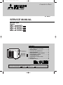
Page 16
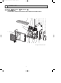
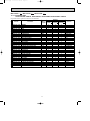
PARTS LIST
MU-A08VD - P1 MU-A10VD - P1 MU-A13VD - P1
10-1. OUTDOOR UNIT
STRUCTURAL PARTS, ELECTRICAL PARTS AND FUNCTIONAL PARTS
16 15
17
13
14
12
11
10
9
18
19
1
2
3
4
5
6
7
8
This figure shows MU-A13VD.
16
OB397--1.qxp
05.3.18 2:12 PM
Page 17
MU-A08VD - P1 MU-A10VD - P1 MU-A13VD - P1
10-1. OUTDOOR UNIT
STRUCTURAL PARTS, ELECTRICAL PARTS AND FUNCTIONAL PARTS
Part number that is circled is not shown in the illustration.
No.
1
2
3
4
5
6
7
8
9
10
11
12
13
14
15
16
17
18
19
20
Part No.
E02
E02
E02
E02
E02
E02
E02
E02
E02
E02
E02
E02
E02
E02
E02
E02
E02
E02
E02
E02
E02
E02
E02
E02
E02
E02
E02
E02
E02
E02
E02
E02
899
927
665
899
900
940
899
900
075
899
900
899
927
899
815
899
900
665
900
899
900
899
900
899
900
927
899
900
899
900
746
746
232
521
501
290
290
900
900
900
506
661
661
662
245
233
374
351
351
353
353
293
293
515
515
523
523
297
630
630
301
301
936
937
Part Name
CABINET
GRILLE
PROPELLER
BASE
BASE
COMPRESSOR
COMPRESSOR
COMPRESSOR
COMPRESSOR RUBBER SET
STOP VALVE (GAS)
STOP VALVE (GAS)
STOP VALVE (LIQUID)
SERVICE PANEL
BACK PANEL
TERMINAL BLOCK
OUTDOOR FAN CAPACITOR
OUTDOOR FAN CAPACITOR
COMPRESSOR CAPACITOR
COMPRESSOR CAPACITOR
SEPARATOR
SEPARATOR
MOTOR SUPPORT
MOTOR SUPPORT
CONDENSER NET
CONDENSER NET
TOP PANEL
OUTDOOR HEAT EXCHANGER
OUTDOOR HEAT EXCHANGER
OUTDOOR FAN MOTOR
OUTDOOR FAN MOTOR
CAPILLARY TUBE
CAPILLARY TUBE
Q'ty/unit
Symbol
in Wiring
MU-A08VD- P1 MU-A10VD- P1 MU-A13VD- P1
Diagram
1
1
1
1
1
1
1
1
Remarks
1
1
1
1
MC
MC
MC
TB
C2
C2
C1
C1
1
1
3
1
3
1
1
1
1
1
1
1
1
1
1
1
1
1
1
1
1
1
1
1
1
1
1
1
1
1
1
3
1
1
1
1
1
1
1
RH135VHCC
RH145VHCC
RH207VHAC
3RUBBERS/SET
{9.52
{12.7
{6.35
2P
1.8µF/440VAC
2.0µF/440VAC
25µF/450VAC
30µF/440VAC
1
1
1
1
1
MF
MF
1
17
1
RA6V21 RA6V33 -
1
{3.0✕{1.6✕850
{3.0✕{1.6✕650
1
OB397--1.qxp
11
05.3.18 2:12 PM
Page 18
OPTIONAL PARTS
REFRIGERANT PIPES
,
The air conditioner has flared connections its indoor and outdoor sides.
Please use the optional extension pipe as follows.
Model
Part No.
MU-A08VDMU-A10VD-
P1
MU-A13VD-
P1
P1
MAC-MS0905F
MAC-MF1305F
Pipe length Cross-section
5m
5m
18
Pipe size O.D mm (in.)
A-Gas
B-Liquid
9.52 (3/8)
Insulation
C
D
[27
[21
[31
[27
[6.35 (1/4)
12.7 (1/2)
Additional
refrigerant
charge
R22(g)
0
OB397--1.qxp
05.3.18 2:12 PM
Page 19
19
OB397--1.qxp
05.3.18 2:12 PM
Page 20
TM
HEAD OFFICE: MITSUBISHI DENKI BLDG., 2-2-3, MARUNOUCHI, CHIYODA-KU, TOKYO100-8310, JAPAN
C Copyright 2005 MITSUBISHI ELECTRIC ENGINEERING CO.,LTD.
Distributed in Mar. 2005. No.OB397 106
Made in Japan
New publication, effective Mar. 2005
Specifications subject to change without notice.