1
I
f
TH u ND ER
s c IE NTI FI c
CORPORATION
.
I
ELECTRONIC PSYCHROMETE R
MODEL 4AI - MP
RELATIVE HUMIDTY · AND TEMPERATURE
MEASUREMENT SYSTEM
OPERATING AND SERVICE MANUAL
_J
DATE
623 WYOMING, S.E. ~
:
j .
ALBUQUERQUE , NEW MEXICO 87123
June
17, 1987
TEL. (505) 265-8701
TABLE OF CONTENTS
PAGE
WARRANTY .
.
.
.
.
.
.
SPECIFICATION S/FEATURES
GENERAL DESCRIPTION
. . .
. . .
. . .
• .
.
...
.
.
PRE-OPERATIONAL INSPECTION .
SET-UP/TURN-O N PROCEDURES
.
. . . .
1
2
3
4
·-
. . . .
. . .
5
PROGRAMMING THE SYSTEM FOR:
MANUAL
OPERATIO~
.
.
.
.
.
6
. . .
HARDCOPY (PRINTER) OUTPUT
.
AUTO MODE OPERATION
.•.
'
8
9
•·
CHANGING THE:
(
\
"
i
...._,,
I
.
HARDCOPY TIME INTERVAL
10
PRESSURE
11
•
•
TIME . .
12
DATE . .
12
SWITCHING TO:
0
c . .
o
F •
•
13
. ·•
. 13
SUMMARY OF COMMANDS:
DISPLAY FUNCTIONS
14
ON/OFF FUNCTIONS
15
SET FUNCTIONS
16
PROBE ~ICK CHANGEOUT INSTRdCTIONS
FACTORY CERTIFICATIO N SERVICE
17
.
DRAWINGS
L)
M83Cl29
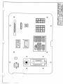
FRONT PANtL DETAIL
DE83C023
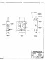
PSYCHROMETER PROBE DETAIL DRAWING
S86D016
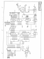
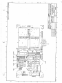
PSYCHROMETER SCHEMATIC DIAGRAM
S83Al30
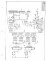
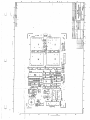
DISPLAY BOARD SCHEMATIC DIAGRAM
S83Bl31
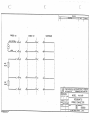
PROBE AND CABLE WIRING DIAGRAM
--\_)
i
(4A~lMP)
.
. 19
;
l
\._ j
u
WARRANTY
Thunder Scientific Corp0ration warrants each instrument of its
manufacture to be free from. defect in ma_terials and workmanship.
The limit of liability under this warranty is to repair or
replace any part thereof which shall within one year after
delivery t0 the original purchaser, and returned by the original
purchaser, prove to be defective after examination by us.
This warranty specifically excludes the probe sensors, which may
become damaged or broken due to wick changes.
Shipping damage
is covered by insurance and will be honored if report is made
within one week of receipt of the instrument.
Warranty returns
mu.st be authorized by the fact0ry.
(
)
u
u
·u
WARNING -- Calibration seals have been applied to the instrument
case, cable, and probe. Should the instrument and/or associated
components be opened or tampered with, or if the seals are
broken, Thunder Scientific Corporation accepts no responsibili ty
for calibration and this warranty is void.
(j
v.· i
4A-1MP - MICROPROCESSOR BASErr WET BULB, DRY BULB PSYCHROMETER
SPECIFICATIONS
Relative Humidity (RH)
Measurement Range:
Guaranteed Accuracy:
Typical Accuracy:
1% RH to 100% RH
+1% indicated RH
+,5% indicated RH
Temperature
Measurement Range:
Guaranteed Accuracy:
Typical Accuracy:
0~100°c / 32-212°F
+.3°C / +.5°F
+.1°C / +.2°F
Readout:
Digital Display:
Printer Interface:
c or °F (user selectable)
,01%RH and .01° Resolution
Trendcom Parallel (std)
Centronics Parallel (opt)
RS-232C Serial (opt)
Trendcom 200 High Speed
Intelligent Printer
0
Printer (optional)
FEATURES
( )
u
*
Z-80
Central Processing Unit,
automatically computes
percent relative humidity and both temperature and dewpoint
in ° C and 0 1''.
*
3 computer/printer interface options: 2 parallel, 1 serial.
*
Battery backed-up real time clock.
*
Timed
printer output mode allowing
user
selectable
intervals from 1 minute to 24 hrs in 1 minute increments.
*
Automatic Mode capability enables probe aspirator
minute prior to each printout.
*
Full function display capability.
*
Not susceptible to contamination by chemicals or long term
exposure to high temperature and relative humidity.
*
Certification of Traceability direct to the National Bureau
of Standards.
u
u
2
for
1
,
\.. )
'
(;·
GENERAL DESCRIPTION
The Thunder Scientific Model 4A-l-MP is a microproc essor based
Laboratory
Standard
Psychrome ter
designed
for
precise
measureme nt of air temperatu re and relative humidity.
The 4A-l-MP uses a 2-bulb measureme nt system employing wet and
dry matched pair calibrated Platinum Resistanc e Thermome ters
(PRT's) operating under a controlled air velocity.
One PRT,
referred to as the dry bulb,
is used for sensing
air
temperatu re.
The other PRT, the wet bulb, uses a specially
weaved wick (or sock) to facilitate an unimpeded capillary flow
of distilled water from a reservoir below.
The wet bulb
measures a depression temperatu re.
The signals from the PRT's are converted to digital format, read
by the micro~rocessor, linearized , and then converted to actual
temperatu re data in both degrees c and degrees F.
The data is
then used to calculate Percent Relative Humidity and Dew Point
Temperatu re.
Front panel display of any of the above data is selected by user
input at the keyboard.
The upper display is the data readout
device, and the lower display indicates which data or other
function is currently enabled. Upon selection of data output to
this real-time LED display, current readings are updated 4 to 5
times each second, allowing for fast system response to any
changes in the sampled environme nt.
Printer output, enabled from the keyboard, allows for hardcopy
printouts of all current psychrome tric data.
Printer output is
at user selectable timed intervals ranging from a 1 minute
minimum to a 24 hour maximum, or at any 1 minute increment in
between.
An Auto Mode feature is also included which, when enabled, will
put the probe in synchrono us operation with the printer.
In
this mode, the probe aspirator will automatic ally run prior to
any sample for hardcopy output.
After printout, the aspirator
will be disabled and will remain off until the next sample time
is reached.
The Model 4A-l-MP is a precise laboratory instrumen t and, if
handled according ly, will provide years of excellent service.
Q)
Q_/
3
u
u
'
\
PRE-OPERATIONAL INSPECTION
The 4A-l-MP Psychrome ter is shipped from Thunder Scientifi c Corp
(TSC) calibrated and basically ready for operation .
Any damage
from shipment should be reported to TSC within one week of
receipt.
Prior to each use, the following inspection should be performed :
1)
Inventory .
. enclosed.
Ensure
all necessary parts and component s are
2)
Inspect
the probe for
cl~anliness.
Pay
particula r
attention to the wick on the wet bulb.
If the wick
requires changing see the section titled PROBE WICK CHANGEOUT INSTRUCTI ONS.
3)
Inspect the main psychrome ter unit.
Ensure the system is
clean,
that all screws and connettin g hardware
are
tightened ,
and that all k~ys operate smoothly without
binding or sticking.
4)
Inspect cables for wear.
nicks,
cuts,
or frays,
easily without binding.
Cables should be free from any
and all connector s should mate
-,/.-
( \
v
4
SYSTEM SET-UP/TURN-ON PROCEDURES
(
1)
Remove the black probe housing from its styrofoam holder in
the display panel.
This housing contains the Platinum
Resistance Thermometers (PRT's). A clean wick. is installed
from the factory on the wet bulb sensor.
To the rear of
the housing is the aspirator motor which draws air over the
PRT's.
2)
Remove the
housing.
3)
Fill the reservoir with pure distilled water.
tap water as this will contaminate the w,ick.).
4)
Replace the filler cap and finger tighten, then gently
shake excess water from inside the white probe cylinder.
Check for leaks around the bottom edge of the housing.
Finger tighten the knurled knob as necessary.
5)
Place the probe in the environment to be tested and then
route and connect one end of the white 12 foot power/signal
cable to the connector on the front of the probe housing.
Connection to the probe should be smooth, as excessive
force could misalign and damage the connectors.
6)
Connect
on the
smooth.
7)
Connect
printer (optional) to
directly above the probe cable.
8)
Connect the 6 foot AC power cable to the
display panel and then to a 120 VAC source.
9)
Turn on the main power switch.
10)
The upper display should show the time in military format,
with a blinking decimal point in the middle (the seconds
indicator).
11)
The lower display should show
Program 7, the time).
12)
Push the LED TEST button and ensure that all segments
all 4 decimal points of each display light up.
)
\..._;'
u
u
knurled filler cap on the bottom of the
probe
(N.ever
use
the other end of the cable to the mating connector
display panel.
Connection here should also be
TURN ON IS COMPLETE.
5
the
P--7
multipin
connector
jack.
(meaning
in
the
Display
and
\.__,;;
PROGRAMMING THE SYSTEM FOR MANUAL OPERATION
\_j
The 4A-l-MP is a. versatile instrument and therefore requires
some input from the user.
The user mu~t perform at least the
following minimum requirements to operate in manual mode:
*
Ensure the 4A-l-MP displays the correct time.
* Ensure the 4A-l-MP displays the corr~ct date.
* Input the atmospheric pressure at the probe environment.
* Turn on the aspirator motor.
* Select the desired display~ ie Temp, Dew Point, RH, etc.
* Turn off the aspirator when measurements are complete.
Detailed descriptions follow:
1)
Display the TIME with the following key strokes:
If the time shown on the upper display is incorrect, follow
the procedure on CHANGING THE TIME.
\_,,·
2)
Display the DATE with the following key strokes:
If the date shown on the upper display is incorrect, follow
the procedure on CHANGING THE DATE.
3)
Input the correct barometric pressure in inches of mercury.
For example, a pressure of 26.53 in Hg would ~e input with
the following key strokes:
For more detailed information,
CHANGING THE PRESSURE.
4)
refer to the section titled
Turn on the aspirator with the following key strokes:
The motor should turn on and the left decimal point of the
lower display should light.
6
5)
Select the desired display output with these key strokes:
Where
6)
X is one of the following:
1 -
% RH
2
3
4
5
6
7
8
Dew Point Temperature
Air Temperature
Wet-bulb Temperature
Resistance of Dry-bulb in Ohms
Resistance of Wet-bulb in Ohms
Time
Date
-
Once measurement is complete, turn off aspirator with:
( )
(
;
\_/
Take additional measurements by repeating steps 4 thru 6.
IMPORTANT NOTE
The fan mounted in the probe housing is
designed with a maximum operating life of 300 hours.
The motor
need not be run for more than 10 minutes before taking
Temperature, Dew Point, or Relative Humidity Measurements.
v
I
'
7
(-,,__/'
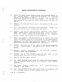
PROGRAMMING THE SYSTEM FOR HARDCOPY OUTPUT
If a printer is connecte d to the 4A-l-MP via the multipin
connecto r
on the display panel,
hardcopy outputs of all
pertinen t psychro metric data are availabl~.
The
followin g
sequence s are used to control the printer output.
Informa tion
is sent to the printer once each minute unless the user changes
the time interval (see CHANGING THE HARDCOPY TIME INTERVA LS).
* Turn on the printer function with the followin g
kaystro~es:
The second decimal point from the left on the lower display
should light.
*
Turn off the printer function with the followin g keystrok es:
,'
\ )
i._!
The second decimal point should go out.
When using the printer,
the aspirato r should also be turned on.
To enable and/or disable the aspirato r,
refer to the previous
section on PROGRAMMING THE SYSTEM FOR MANUAL OPERATION.
Any one of
availab le:
1)
2)
3)
the
followin g
printer/c omputer
Trendcom compati ble paralle l
Centron ics compati ble paralle l
RS~232C serial, 300 to 9600 Baud
Consult TSC for your particu lar requirem ents.
8
interfac es
are
u
{
\
\,_,)
PROGRAMMING THE SYSTEM FOR 'AUTO MODE' OPERATION
In 'Auto Mode' operat ion, the aspira tor motor functio n is
automa tic and is under comput er contro l. If the hardcop y output
is enable d, (as previo usly describ ed), the comput er will turn on
the aspira tor precis ely 60 second s prior to print time, and will
turn the motor off immed iately after print.
This feature
extend s the service of the aspira tor motor which has a 300 hour
maximum
run-lif e.
It
also provid es for
accurac y
and
repeat ability of measur ements , as the motor is run for equal
amount s of time prior ta each and every printo ut.
* To enable the Auto Mode, type the followi ng keystro kes:
Now anytim e the printe r is enable d,
(see PROGRAMMING THE
SYSTEM FOR HARDCOPY OUTPUT), the probe will automa tically
turn on and off at the correc t times.
( )
u
* Disabl e the Auto Mode functio n with the followi ng k.ey stroke s:
The Auto Mode is now disable d and contro l of the aspira tor
is solely under user keyboa rd contro l.
The printe r
functio n is not affecte d.
Note - Defaul t interv al is 1 minute betwee n printo uts.
This
means that in the Auto Mode, when the printe r functio n is
enable d, the motor will stay on continu ously unless the time
interv al is changed tsee CHANGING HARDCOPY TIME INTERVALS).
Note - If the motor happen s to be on when either the Auto Mode
o-r--th e printe r functio n is turned off from the keyboa rd by the
user~
the aspira tor motor may also need to be turned off in the
same manner .
u
u
9'
i
\.._
.
_//
\
CHANGING THE HARDCOPY TIM
E INTERVAL
\._ )
Th e 4A -l-M P is ca pa ble
oth er de vic e, suc h as a of sen din .g da ta to a pr in ter or some
Th e inf orm ati on se nt co nsco mp ute r, at sp ec ifi ed tim e in ter va ls.
and De wp oin t tem pe rat ure ist s of Da te, Tim e, Dry Bu lb, Wet Bu lb,
Va po r Pr ess ure ov er wa ter s, Re lat ive Hu mi dit y, and sa tu rat io n
A he ad er is se nt be for at the Dry and Wet Bu lb tem pe rat ure s.
e the fir st lin e of
ta and ev ery 23
lin es th er ea fte r.
The tim e be tw een eac h pr da
int ou t de fau lts to
the minimum in ter va l of 1
on , bu t is ke yb oa rd se lec mi nu te eac h tim e the sys tem is tur ne d
tab le up to 24 ho urs .
*
To ch an ge the INTERVAL,
exa mp le ch an ge s the in ter vafol low the sam ple be low .
Th is
can use yo ur own in ter va l l to 1 ho ur 25 mi nu tes (bu t you
ins tea d) .
(
\
J
(_./
No te th at the num ber on
when the SET key is pu she the low er dis pla y be gin s fla sh ing
d.
When the EN'l'ER key is pu she
the num ber sto ps fla sh ing
,
ind ica tin g tha t the co mp d,
ack no w,l edg es the key and
ute r
is now
inp ut.
Th e in ter va l nu mb ers wi aw ait ing the in ter va l
ll ap pe ar on the up pe r
dis pla y, sh ift in g the old
nu
mb
ers
ou t to the le ft as the
new nu mb ers are pu nch ed in.
(T
his
sam
e pro ce du re oc cu rs for
al l SET com ma nds ; ie, Pr es
su re, Tim e, and Da te. )
10
l
l
\._/
CHANGING THE PRESSURE
The 4A-l-MP has been programmed from the factory with a
barometric pressure of 29. 92 inches of mercury (in HG).
The
instrument uses the barometric pressure for all calculations of
Relative Humidity and D.ewpoint temperature.
rt. is recommended
that the absolute pressure be measured in the environment where
the probe is to be set up and used. The pressure should also be
measured frequently during the operation of the system, as the
accuracy of the calculations can differ as much as 2%RH for
every inch of mercury.
To change the PRESSURE, follow the sample
example changes the pressure to 25.75 in HG.
\, )
u
below.
This
You must type in all 4 digits including the decimal point.
For an explanation of the upper and lower display readings
during this k~yboard sequence, refer to CHANGING THE
HARDCOPY TIME INTERVAL.
u
\...._,,..i
11
u
\_)
CHANGING THE TIME/DATE
The 4A-l-MP contains a battery backed-up Real Time Clock.
The clock operates on a four year calendar, meaning that it
makes no adjustmen t for leap year. Should it require setting for
any reason, refer to the below procedure s.
*
To change the TIME, follow the sample below.
bhanges the time to 3:40 PM.
This eKample
Note that the time is input in MILITARY FORMAT, and that no
decimal point is needed between the hours and minutes. Far
an explanatio n of the display readings during this keyboard
sequence, refer to CHANGING THE HARDCOPY TIME INTERVAL.
( )
L;
*
To change the DATE, follow the sample below.
change the date to June 4th.
This would
Note that June was input as '06' and that the day was input
as '04'. Both digits of each must be typed.
12
u
u
SWITCHING TO
°C/~F
The 4A-l-MP is capable of both °C and °F operation.
The user
may at any time select which mode to use.
When switched, all
temperature displays,
in6luding hardcopy output,
will be
affected. Th€ temperature data sent to the hardcopy device will
be followed by C or F as applicable.
*
To switch to °C, type the following
*
To switch to
0
~eystrokes:
'F 1 type these keystrokes:
NOTE - The pow.er up default mode is °F.
u
13
u
u
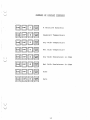
SUMMARY OF DISPLAY COMMANDS
[8J8~B
( )
u
% Relative Humidity
ssrn6
Dewpoint Temperature
B8GJ6
Dry Bulb Temperature
[8]8~~
Wet Bulb Temperature
s:s~.[i]·
Dry Bulb Resistance in Ohms
BBm~
Wet Bulb Resistance in Ohms
88~·~·
Time
B88B
Da. te
14
u
u
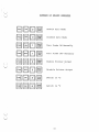
SUMMARY OF ON/OFF COMMANDS
BB~~
BB~.~
BB~~
(
u
u
)
(
88, [[][i ]
88[ ;][i ]
Enable Auto Mode
Disable Auta Mo<le
Turn Probe ON Manually
Turn Probe OFF Manually
Enable Printer Output
/
sram~
Disable Printer Output
BB.[[]~
switch to
srBm~
Switch to °F
1
u
15
0
c
.
\_. )
(_)
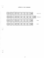
SUMMARY OF SET COMMANDS
BBGJBGJGJBGJ6
LGJBLQJBGJGJDGJGJm
8BGBGJGJBBliJ
8BGJBGJDGJGJ[i]
;
\
; v
:
;
~
I,
i
u
; u'·
.
.
16
Interval
Pressure
1
'ime
Date
u
u
PROBE WICK CHANGEOUT INSTRUCTIONS
The CK-1 Wick Changeout Kit is provided to easily change wicks
in the sensing probe.
Wick changes should be performed after
forty hours of operation, or more often, particularly if the
instrument is in a dirty environment. A replacement wic~ supply
should be ordered from Thunder Scientific Corporation in advance
of the need and kept on hand.
Order
PW~lOl
Probe Wick
$10.00 each
Suggested Stock:
Minimum Order:
F.O.B.
(
I
v
u
u
25
$50.00
Albuquerque, New Mexico 87123
lf
Place probe upside down upon. two blocks of wood or
material, one on each Side of the probe handle.
2)
Remove reservoir plug and rubber feet.
3)
Gently pry reservoir cover with plastic tool and remove.
4)
Carefully remove the four housing retainer screws located
in the corners of the probe; They join the two halves of
the probe.
5)
Gently remove bottom half of probe housing, feeding the
wick through the teflon wick tube.
Keep the teflon a.ir
sleeve in place during removal.
NOTE - Blower motor is also loose once housing is removed.
6,)
Lift tef lon air sleeve up and off the sensor rnoun ts, taking
care to feed the wick through the air sleeve avoiding any
lateral movement and undue strain upon the sensor.
7)
The sensor and wick are now in the open where the wick may
be
removed.
using the dropper provided, apply several
drops of
ethyl alcohol to the portion of the wick
covering the sensor.
Allow to soak for approximately
one minute, replenishing the
alcohol as evaporation
occurs.
8)
Using one of the picks provided,
covering the sensor to loosen.
9)
Using the curved tweezers provided, very gently push the
wick
up on itself or up on the sensor, assisting with
the other hand from the reservoir side.
(The wick
construction is very similar to a "Chinese finger puzzle"
in that pushing tends to release it where pulling only
other
.
l
...,
gently probe
the
wick
\_)
u
tightens the wick and compoun ds the problem of removal ).
The wi.ck should expand. When this occurs, use the tweezers
to slide the wick from the sensor.
IMPORTANT! - If wick is frozen to the sensor with deposits
due to contami nated water, DO NOT FORCE.
This will break
the sensor leads, causing expensiv e repair costs.
If
alcohol does not loosen the deposit , return to Thunder
Scienti fic Corpora tion for removal.
Thunder Scienti fic is
not respons ible for lead break.age and/or sensor replacem ent
if such occurs.
If a wick changeo ut schedule is maintain ed,
will not occur.
(. )
this
problem
10)
Apply finger cots supplied to the thumb and index finger of
each hand.
soak a clean cloth with alcohol and remove all
traces of talcum from the outer surfaces .
If this is not
done, the wick becomes contami nated.
11)
The replacem ent wicks are supplied in a sealed
alcohol. Remove wick from the vial.
12)
Using the blue taper tool provided , push the wick onto the
tool approxim ately one inch or more, causing expansio n by
pushing on the wick.
13.)
Remove from tool and clip frayed end square.
14)
Slide wick
shoulde r.
15.)
Using the dropper , apply several drops of w.ater on the wick
at the sensor.
Note wick expands slightly , indicati ng
water retentio n. Gently form the wick around end of sensor
and flatten between the sensor and wick tube to offer
minimum wind resistan ce.
16)
Feed wick thru teflon air sleeve, slide sleeve over teflon
sensor mounts, and seat it on the probe half.
17)
Feed wick thru wick tube in bottom probe half and mate the
probe halves.
Coil wick inside reservo ir and replace
cover.
18)
Replace
plug.
u
four
vial
gently onto sensor and over the teflon to
corner screws,
18
rubber feet,
and
of
the
reservo ir
FACTORY CERTIFICATION & RECERTIFICATION
Factory certifica tion is initially ~rovided with each DBW
instrumen t on a. no-charge basis. Certifica tion is good for one
year or longer: However, the instrumen t should be recertifie d by
the factory on a re9ular yearly basis.
This is done for a
calibratio n charge of $200.00 per temperatu re and humidity
point.
Generally , three temperatu re and humidity points are
sufficien t.
If the instrumen t requires more than genBral
cleaning, a reconditio ning charge of $150.00 is required.
NBS CERTIFICATION & RECERTIFICATION
If it is desired that the instrumen t be certified by the
National Bureau of Standards (NBS), all NBS charges are passed
net to the customer, plus F.O.B. charges to and from, plus
insurance coverage.
(
)
In the case of NBS certifica tion, Thunder Scientific Corporatio n
does require that the instrumen t be shipped direct from Thunder
to NBS and returned prior to shipment to the customer. The same
is required for recertific ation.
The instrumen t should be
returned to Thunder Scientific for inspection and reconditio ning
prior to recertific ation by the Bureau.
u
********
SUMMARY
Your Thunder Scientific psychrome ter is a precise laboratory
standard and should be treated according ly.
Good maintenan ce
will result in many years of service.
Should
any problems or question arise relative to
your
instrumen t, direct all correspond ence to the following address:
Thunder scientific Corporatio n
623 Wyoming S.E.
Albuquerq ue, New Mexico 81123
Or call collect (505) 265-8701
1Q
i !.
'-)
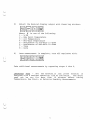
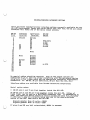
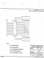
PRINTER/COMPUTER\ INTERFACE OPTIONS
There ar:-e three computer/p rinter interfac:e options cur:-r:-ently available for:- the
4A--1-MP Psychr;-orneter:-. Based upon which option' your;- unit has, the 25 pin output
connector w.i ll match one of the below 1 isted pinouts.
DB,...25
Pins
1
2
3
4
5
6
7
8
9
Trend~om
Parallel
Gr;-ound
D1
03
D5
07
11
15·
16
17
18
19
20.
21
22
23
24
25
Strobe
01
02
03
D4
05
06
D7
XMIT Data
* RTS
* CTS
** DSR
Ground
Busy
1,2
13
RS-232
Sel'.'i al
D0
10·
14
Centronics
PClr;-allel
Busy
Strobe
00
D2
04
D6
Ground
Ground
Gi'i'ound•
Ground
Gi'i'ound
Ground
Gi'i'ound
**
DTR
No special cables shou ld be required. Each, of the output options al':'e
configured so as to make the proper connections with the peripheral· device
using onJ.y a flat ribbon cable and the appropdate insulation displacemen t
connectors. ( ie DB-25, 36 pin· Centr:-onks, 20 pin Dual Row IDC, etc. )
1
Interface cables ar:-e available frorn Thunder Scientific Corporation .
Serial option notes:
*
**
DB-25 pins 4 and 5 ar:-e tied together inside the 4A"-1-MP~
DB-25 pins 6 and 20. are tied together inside the 4A-1-MP.
Either of
these 1 ines rnay be used: as a BUSY/READY handshake. lir1e. If handshaking
' is
used, the receiving device shou:ld be able to accept one more fuill character
in addition to the one ct..trrentlyb eingsent due to the da.uble-buff ered
nature of the UART used within: the 4A'-1-MP.
Signals g!'l'eater than +5 volts
Signals greater than -5 volts
(
u
= READY
= BUSY
lf pins 6 and 20 are leflt ur;iterminate d, READY is assurned.
-
--
If
(1)
J
co
'
OJ
an
II
""
I
.€9.
(
J
)
~·
E
=
C\J
•
-
01
'
,._ I VI
,\
-
-
c--,
-
·--·-·
RESERVOIR (REMOVABLE COVER
FOR ACCESS) THREADED INSERT
.5DO" DEEP 1/4-20
SCREW (4 PLCS.I
RUBBER FEET
(4 PLCS.I
PRT ELEMENT
(WET BULB)
PRT ELEMENT
(ORY BULB!
KNURLED KNOB
(REMOVABLE I
.y· ., , ==· ."' . . :l-"""""
FAN
--.... >z I
l!~!J
FRONT VIEW
AIRFLOW
I I''. I >•'<
~
_,,.
~rl
\._l.
SIDE VIEW
AIRFLOW
BOTTOM VIEW
THUNDER SCIENTIFIC CORP
61] WYOMING S.I.
fou:R"..;[j
::~'.:2···
I _"."•v•••O"'•-----
1-1 .... I .. I
AUUQUUQUI. NIW '41 •ICO 171'Jl
---- --psYCHROMETEll --
I
MODEL 4A-IMP
...
NA
............- ---
DE83G023
11:!n-eon -11•·1111~11·11r· -
0z
,, §
~
~
I•
>r
::s
6~
I•
[
!!
c
·,
\_J
;
~~
"'~
:1.L-~----i
,,:!
~~1 -
~
(
v
;
.
t
1
~· st1
',
,.
I
#~
r:lJ -_..•
.
-~ -- :t
~;f·"-"'
"'~
t•
4
'J".11 : f
.,
:~~~~:.~
~1~=
~.t.'
:.?: ' "• '
.....
I
~
s;
I
~
c
.
..
%
0
ID
<
er
[
...er
O'
0
;::
:i:
w
tj,
...
Q
;::
.
J
~
5
"
..
rs"' 1' <~
"'
%
..
I
l:.
er
'
w
c
:z
~
.,i
.J
~
....
0
I!
N'
·•>
~
.,r:oJ.
=o!
O!
~_..._0!--4
~i··1r1JJ~J
_,a·~
°''
'.........
/
.,
,
0
"/
W·Ct,01
/
-
~ ~
(
.i
I
I
"'
<
0
O'
G
:
8
Q
~
!:
j
.,
0
Q
J~
(
',
\..__/
..,
..,
0'
~1
r-EF-i
.~~
~~
?~
~1
I
i
l_,,;
I
I .tl ..
'
4~
-u"
1
I I
~
.$
'!~
.':2
"
"~II
...
~Q
,i~rJI
s~
JQ
,,"
u
~
if -- ! - - --ol
..
- - "'
--- -
-
~'S
.."
~~
~~
. 1---9
~~
~"'
'tr~
..
s~
~
f: -.:-::.:: .~ =--=------: :-_:-_-_-------- - - --
.
:l
!c
g3
'
c
c_=
c_:_
...----- .------1
REVISION.;;.S_ _
LTR
4
II
12
-
12
-
- --
~-
10 , __
9
------
1-----
3
--
--
--
-
-
---
-
--
-
a
13
b 3
14
c
6
--
-
4
II
5
--
13
l'I
-
--
2
I
----
--
---
---
-
--
IQ
--
7
•
28
...,;._.
--
---
-
-
- APPROVtD
I
II
3
8
13 12 16 15
f
--
-
27
--
-
--
----
I
----
-----
---
---
2
--
I 24
--
--
--
-
-
-
-
Q 26
4
19
5
--
d 25
UI
8
-
--
10 14
15 16 3 23
I 2
4 20
--DAf(
LI
7
l
-
DESCRIPTION
8 7
16 21
-
ll 17
-
622
- --
.,
-
I
l
7
10
I
4
I
II -8
3
13 12 16 15
L2
14
NOTES::
, 1. u1·1s AN
-·
LED
DRIVER SYSTEM.
.-
2. L 1 ANO L2 ARE
- --- THUND ER SClEN TlFIC CORP
LED DISPLA.vs:
Ul WYOMING I.I,
,
3. J1 IS A 14-PIN CONNECTOR, SHOlJU) COf\l\ECT·
WITH J3 OF tv'0Tl-ER BOARD BY~
4. Pro A .1 tv'F .CAfl. BETWEEN PIN 9 & 19 Of=U1,
.
.
tOlc1U.-t1CCI- UHUll ----OTHUWll[ ll'lCIPllD
fAACTIOHI DCC
AHOLU
:I:
:I:
:I:
Al'PAOVALS
-
-
-----
-
-
-
DR.AW'D·A· V.Zi.5·63
---
--
--
--
NEW
DISPLAY SCHEMATIC
CtUCRlO
-
-
4A ... ·1-MP
----
DATE
-
f\ .-•\MO~ -C-lllA.~MiC1 IHC:
II •tOllOI.• litO )0\11
AllUOUllO!JI , NIW MllllCO 11111
-
SCAl[
-r\JA ----1
8 1DRAs'a3°A 130
5
oo Nor scAu 011Aw11m -- --- 1utm 1
or
1
C
~·,
C.
,__ .--·
(_
REVISIONS
-Cl(SCR11'110H -
LTR
PROBE 1/2
CABLE 112
I
I
+26V RETUR
I
I
1
A'
~
I
I
I
I
I
I
I
I
+26V
I
Di
~
.
I
I
~
I
I
I
I
I
I
B'
~
- I
1
(B
.
I
WET
I
BULB
I
I
I
4-<
I
I
o,_(
I
I
I
Bl (
r
"I:::
'
I
I
-(E'I
-
I
I
I
I
I
I
_I
I
I
I
I
(61I
.
I
:
-!
I
I
lI
I
I
I
<~
I
I
I
I
-
- -
I
I
I
I
I
I
I
--
I
I
I
I
I
I
I
I
I
I
I
I
I
I
1I
A
~I
. I
I
I
I
I
,.F 1
I
~
. I
(
I
I
I
I
DRY
BULB
I
I
I
I
I
I
I
I
I
I
I
A'I
I
F
I<
I .
I
I
I
I
I
Et, - (
I
I
I
I
<F1
.
j
I
I
I
I
I
I
II
( E!::.a1-.,...-=- -
.
I
I
I
I
I
-THUND ER SCIENT IFIC CORP
I
I
I
6ll WYOMING S,l,
fMCTK>HI
;I:
fn'\·11~-"°" ~11....,.,..•CI
llritC.
4A+·MP
;I:
SCEMEMATIC
OAAW"t:>R.h
CHtC•LD
'AllUOUUOUI, HM MIXICO 1711l
MODEL
Of..C
;I:
AF'PAOVAlS
"rlll ALO•OU JIO, 111>\JI
- APP!IOvtO
MAINFRAME
I
A
<I
.
OATl-
SCAlC- -
- DO
PROBE CONNECTOR
IDRAWIHGSB3Bl31
-'8
NOT SCALE
OR-AWING -
-
I SHCCT
...
v
i
I
-
i
i
i
. \_)
I
N
WI
;i~
1.
,,.,
i
1!1,,.,
'
.
-~'~
llC~o
I
. .
•••••••• ••••••••
•
u
8
....
.. _
.
•
•
=O O"
•
•
•
g
•
•••••••• ••••••••
•
0
+
•
•
•
..,
·D
v
I
e
:n ·······
········
~·
-ooz
2!'0
,,i;·,
002•~
-·
~
~-_,._e<>_,,i;·,~s~
i
. . .
I
~- ·I~ .·- .,._ " _
~: --0-20 5·
. • • .f;;§ • .
• ~~
§El
. !--G!l • ,
.
,•
.';
·· ····· ···· ····
lI
(
18
.)
\
. .g.-.
"
i
I: I'I I''111
-'. i 11 I
..
1~1~
. ,i:
:,II
. : ; 1111
. .:i•
• I I
I'"!
.~ ;~ ;I i I Iiii
. I I
I
'
I
Q
l
~ • • • • ·liill:l ...~ · -
;i
~ .•. ·····:· ~tR r·····:· ···:···
...
.o o·
!~
•""R,..
fj Q
o
<•I!_-~
:;
•
•
•
•
o,
~f
I:>
•
u, -
•
.
::
o
J
i!J
~
•
... : ... ········
lltt•L.!._.•
Z.)b 8tt1•t-...!,_JI'
•
""
v u
•
e
-u·voc
e
41llYOC
e
."
N
::>
•
,..,
......•• ........
•
•
....•..• ........
.·o o.
~ei
o..
........ .......
Citi•:_..L-•
lttf~;«E
........ ........
•
:- •
0
•
•
•• •• • ••• • • • • • •• •
e
•l'VDC
e
IWITCKED 14V lltE:TUfl.N
a
a
.. ,.
a~
2
0
u
~l -
·. ~~:::~:::::1. . .
Q ••
UY,COLMOW
IV COl.IMION
t9 :~:::·:::i. . a~~/:~1G
UY·llETUlllN
YDC