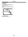
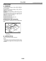
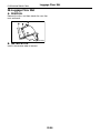
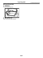
1
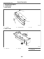
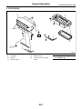
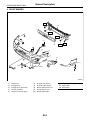
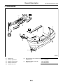
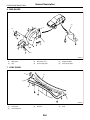
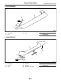
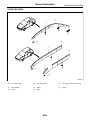
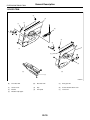
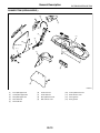
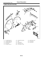
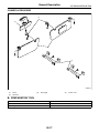
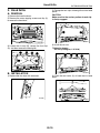
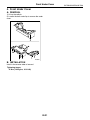
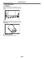
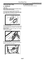
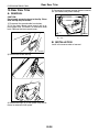
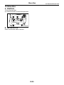
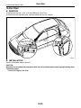
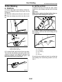
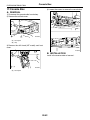
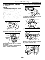
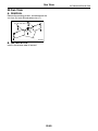
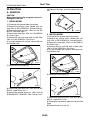
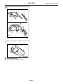
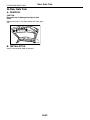
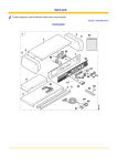
2004 IMPREZA SERVICE MANUAL
QUICK REFERENCE INDEX
BODY SECTION
This service manual has been prepared
to provide SUBARU service personnel
with the necessary information and data
for the correct maintenance and repair
of SUBARU vehicles.
This manual includes the procedures
for maintenance, disassembling, reassembling, inspection and adjustment of
components and diagnostics for guidance of experienced mechanics.
Please peruse and utilize this manual
fully to ensure complete repair work for
satisfying our customers by keeping
their vehicle in optimum condition.
When replacement of parts during
repair work is needed, be sure to use
SUBARU genuine parts.
All information, illustration and specifications contained in this manual are
based on the latest product information
available at the time of publication
approval.
FUJI HEAVY INDUSTRIES LTD.
HVAC SYSTEM
(HEATER, VENTILATOR AND A/C)
AC
HVAC SYSTEM (AUTO A/C)
(DIAGNOSTICS)
AC(diag)
AIRBAG SYSTEM
AB
AIRBAG SYSTEM (DIAGNOSTICS)
AB(diag)
SEAT BELT SYSTEM
SB
LIGHTING SYSTEM
LI
WIPER AND WASHER SYSTEMS
WW
ENTERTAINMENT
ET
COMMUNICATION SYSTEM
COM
GLASS/WINDOWS/MIRRORS
GW
BODY STRUCTURE
BS
INSTRUMENTATION/DRIVER INFO
IDI
SEATS
SE
SECURITY AND LOCKS
SL
SUNROOF/T-TOP/CONVERTIBLE TOP
(SUNROOF)
SR
EXTERIOR/INTERIOR TRIM
EI
EXTERIOR BODY PANELS
EB
G1870GE6
2004 IMPREZA SERVICE MANUAL
QUICK REFERENCE INDEX
BODY SECTION
CRUISE CONTROL SYSTEM
CC
CRUISE CONTROL SYSTEM
(DIAGNOSTICS)
CC(diag)
IMMOBILIZER (DIAGNOSTICS)
IM(diag)
G1870GE6
EXTERIOR/INTERIOR TRIM
EI
1.
2.
3.
4.
5.
6.
7.
8.
9.
10.
11.
12.
13.
14.
15.
16.
17.
18.
19.
20.
21.
22.
23.
24.
25.
26.
27.
28.
29.
30.
Page
General Description ....................................................................................2
Front Grille ................................................................................................18
Hood Grille ................................................................................................19
Front Under Cover ....................................................................................21
Front Bumper ............................................................................................22
Rear Bumper.............................................................................................28
Mud Guard ................................................................................................31
Cowl Panel ................................................................................................32
Roof Spoiler ..............................................................................................33
Rear Spoiler ..............................................................................................35
Side Sill Spoiler .........................................................................................36
Front Door Trim .........................................................................................37
Rear Door Trim .........................................................................................38
Glove Box..................................................................................................39
Roof Rail ...................................................................................................40
Roof Molding .............................................................................................41
Console Box..............................................................................................42
Instrument Panel Assembly ......................................................................43
Upper Inner Trim .......................................................................................46
Lower Inner Trim .......................................................................................47
Rear Quarter Trim .....................................................................................48
Sun Visor...................................................................................................49
Roof Trim ..................................................................................................50
Rear Gate Trim .........................................................................................52
Rear Shelf Trim .........................................................................................53
Trunk Trim.................................................................................................54
Floor Mat ...................................................................................................55
Luggage Floor Mat ....................................................................................56
Trunk Room Mat .......................................................................................57
Heat Shield Cover .....................................................................................58
General Description
EXTERIOR/INTERIOR TRIM
1. General Description
A: COMPONENT
1. FRONT GRILLE
(3)
(1)
(2)
EI-00413
(1)
Front grille
(2)
Front grille emblem
(3)
Clip
2. UNDER COVER
(1)
T
(2)
EI-00414
(1)
Under cover
(2)
Clip (side)
Tightening torque: N·m (kgf-m, ft-lb)
T: 14 (1.42, 10.3)
EI-2
General Description
EXTERIOR/INTERIOR TRIM
3. HOOD GRILLE
(1)
(3)
(2)
(4)
T
(5)
T
(2)
EI-00842
(1)
(2)
(3)
Hood grille
Packing
Grille duct upper
(4)
(5)
Grille duct lower
Intercooler water spray (STi
model)
EI-3
Tightening torque: N·m (kgf-m, ft-lb)
T: 4.5 (0.46, 3.32)
General Description
EXTERIOR/INTERIOR TRIM
4. FRONT BUMPER
T2
(10)
T1
T2
(5)
(9)
(6)
T2
T1
(7)
(1)
(2)
(4)
(8)
(3)
EI-00848
(1)
(2)
(3)
(4)
(5)
Bumper face
Fog light cover
Fog light cover (STi model)
Air dam skirt ASSY
Bumper bracket side upper
(6)
(7)
(8)
(9)
(10)
Air spoiler side bracket
Air spoiler upper bracket
Bumper bracket side lower
Energy absorber form
Bumper beam ASSY
EI-4
Tightening torque: N·m (kgf-m, ft-lb)
T1: 32 (3.3, 24)
T2: 69 (7.0, 51)
General Description
EXTERIOR/INTERIOR TRIM
5. REAR BUMPER
T2
(7)
(6)
(1)
T1
(2)
T3
(3)
(4)
(5)
EI-00849
(1)
(2)
(3)
(4)
(5)
Bumper face
Bumper upper beam
Bumper corner bracket
Bumper side bracket
Bumper side cover
(6)
Energy absorber form (model with
bumper beam)
(7)
Back beam ASSY (model with
bumper beam)
EI-5
Tightening torque: N·m (kgf-m, ft-lb)
T1: 33 (3.4, 24)
T2: 34 (3.5, 25)
T3: 95 (9.7, 70)
General Description
EXTERIOR/INTERIOR TRIM
6. MUD GUARD
(6)
(2)
(5)
(1)
(3)
(4)
EI-00419
(1)
(2)
Mud guard
Clip
(3)
(4)
Sub frame cover
Front air flap plate
(5)
(6)
Mud guard plate
Rear air flap plate
7. COWL PANEL
(2)
(3)
(1)
(4)
(2)
EI-00420
(1)
(2)
Cowl panel
Cowl side panel
(3)
Protector
(4)
EI-6
Seal
General Description
EXTERIOR/INTERIOR TRIM
8. ROOF SPOILER
(1)
(2)
T
(3)
EI-00421
(1)
(2)
Roof spoiler
Cap
(3)
Clip
Tightening torque: N·m (kgf-m, ft-lb)
T: 7.4 (0.75, 5.46)
9. REAR SPOILER
(1)
(5)
(2)
(6)
(3)
T
(4)
EI-00422
(1)
(2)
(3)
Rear spoiler
Protector
Clip
(4)
(5)
(6)
Grommet
Seal (RH)
High mount stop lamp
EI-7
Tightening torque: N·m (kgf-m, ft-lb)
T: 7.4 (0.75, 5.46)
General Description
EXTERIOR/INTERIOR TRIM
10.SIDE SILL SPOILER
(2)
(4)
(1)
(5)
(3)
(6)
(4)
EI-00423
(1)
(2)
Side sill spoiler
End cover
(3)
(4)
Protector
Rivet clip
(5)
(6)
Clip (Side sill spoiler)
Clip
11.ROOF RAIL
(1)
T
T
EI-00424
(1)
Roof rail
Tightening torque: N·m (kgf-m, ft-lb)
T: 7.4 (0.75, 5.46)
EI-8
General Description
EXTERIOR/INTERIOR TRIM
12.ROOF MOLDING
(A)
(1)
(4)
(5)
(3)
(2)
(B)
(1)
(C)
(1)
(3)
(1)
(3)
(2)
(2)
EI-00443
(A)
For sedan model
(B)
For wagon model
(C)
For wagon model (with roof rail)
(1)
(2)
Roof molding
Clip A
(3)
(4)
Clip B
Clip C
(5)
Clip D
EI-9
General Description
EXTERIOR/INTERIOR TRIM
13.DOOR TRIM
(4)
(5)
(3)
(1)
(6)
(2)
(4)
(2)
(5)
(A)
(3)
(6)
(C)
(B)
(7)
EI-00425
(A)
Front door trim
(B)
Rear door trim
(C)
Rear gate trim
(1)
(2)
(3)
Gusset cover
Bracket
Weather strip upper
(4)
(5)
Clip
Trim panel
(6)
(7)
Power window switch cover
Lower trim
EI-10
General Description
EXTERIOR/INTERIOR TRIM
14.CONSOLE BOX
(1)
(2)
(5)
(4)
(6)
(3)
(12)
(14)
(7)
(8)
(15)
(13)
(9)
(10)
(11)
EI-00533
(1)
(2)
(3)
(4)
(5)
Console cover
Cup holder
Bracket
Strip
Upper lid
(6)
(7)
(8)
(9)
(10)
Lid hinge
Rear lid
Console box
Console pocket
Upper bracket
EI-11
(11)
(12)
(13)
(14)
(15)
Lower bracket
Lock
Front cover (AT model)
Front cover (MT model)
Boot
General Description
EXTERIOR/INTERIOR TRIM
15.INSTRUMENT PANEL
(6)
(2)
T
(3)
(1)
T
(4)
(5)
(10)
(8)
(9)
T
(7)
(4)
(19)
(11)
(17)
T
(18)
(12)
(15)
(13)
(16)
(14)
EI-00427
(1)
(2)
(3)
(4)
(5)
(6)
(7)
(8)
Pad & frame
Center upper panel
Air vent grille (defroster)
Grille cover
Meter visor
Defroster grille
Cup holder
Air vent grille (center)
(9)
(10)
(11)
(12)
(13)
(14)
(15)
Air vent grille (side)
Instrument panel lower cover
Console cover
Center panel
Center pocket
Ash tray
Audio bracket
EI-12
(16)
(17)
(18)
(19)
Glove box lid
Glove box panel
Console reinforcement
Coin box
Tightening torque: N·m (kgf-m, ft-lb)
T: 7 (0.71, 5.2)
General Description
EXTERIOR/INTERIOR TRIM
16.INNER TRIM (SEDAN MODEL)
(13)
(3)
(2)
(1)
(8)
(4)
(9)
(10)
(12)
(11)
(7)
(6)
(5)
EI-00429
(1)
(2)
(3)
(4)
(5)
Front pillar upper trim
Center pillar upper trim
Rear pillar upper trim
Rear shelf trim
Rear bulk trim
(6)
(7)
(8)
(9)
Trunk rear trim
Trunk side trim
Rear pillar lower trim
Side sill rear cover
EI-13
(10)
(11)
(12)
(13)
Center pillar lower trim
Side sill front cover
Front garnish
Rear garnish
General Description
EXTERIOR/INTERIOR TRIM
17.INNER TRIM (WAGON MODEL)
(3)
(2)
(4)
(1)
(13)
(6)
(9)
(10)
(5)
(12)
(7)
(11)
(8)
EI-00430
(1)
(2)
(3)
(4)
(5)
Front pillar upper trim
Center pillar upper trim
Rear pillar upper trim
Rear rail trim
Rear pillar lower trim
(6)
(7)
(8)
(9)
(10)
Rear quarter lower trim
Hook
Rear skirt trim
Side sill rear cover
Center pillar lower trim
EI-14
(11)
(12)
(13)
Side sill front cover
Front garnish
Rear garnish
General Description
EXTERIOR/INTERIOR TRIM
18.ROOF TRIM (SEDAN MODEL)
(1)
EI-00431
(1)
Roof trim
19.ROOF TRIM (WAGON MODEL)
(2)
(1)
(3)
EI-00432
(1)
Roof trim
(2)
Roof trim (Model with sun roof)
EI-15
(3)
Sun roof garnish
General Description
EXTERIOR/INTERIOR TRIM
20.LUGGAGE FLOOR MAT
(4)
(3)
(2)
(5)
(1)
EI-00433
(1)
(2)
Front floor mat
Floor box
(3)
(4)
Side floor mat (RH)
Center floor mat
(5)
Side floor mat (LH)
21.HEAT SHIELD COVER
(3)
(2)
(1)
EI-00089
(1)
Front heat shield cover
(2)
Center heat shield cover
EI-16
(3)
Rear heat shield cover
General Description
EXTERIOR/INTERIOR TRIM
22.INNER ACCESSORIES
(1)
(4)
(2)
(3)
EI-00434
(1)
(2)
Hook
Sun visor
(3)
Assist grip
(4)
Center visor
B: PREPARATION TOOL
TOOL NAME
Clip remover
Clip clamp pliers
REMARKS
Used for removal of trim.
Used for removal of various clips and clamps.
EI-17
Front Grille
EXTERIOR/INTERIOR TRIM
2. Front Grille
A: REMOVAL
1) Open the front hood.
2) Remove the four clips (A).
: (A)
EI-00407
3) Remove the right and left hooks on the lower
side.
EI-00476
B: INSTALLATION
Install in the reverse order of removal.
EI-18
Hood Grille
EXTERIOR/INTERIOR TRIM
3. Hood Grille
2) Engage the four clips of hood grille to front hood
panel.
A: REMOVAL
1) Remove the hood insulator.
2) Remove the seven tapping screws and clip (A)
to remove the hood duct.
CAUTION:
Make sure that the anchor portion of each clip
is firmly engaged.
(A)
EI-00447
EI-00444
3) Loosen the six nuts (B), remove the four clips
(A), and then remove the hood grille.
(A)
Tightening torque:
4.5 N·m (0.46 kgf-m, 3.32 ft-lb)
(A)
(B)
(A)
3) Install the six nuts.
(A)
EI-00445
EI-00448
B: INSTALLATION
1) Replace the four clips with new ones.
4) Catch the two hooks (A) of hood duct to hood
holes.
(A)
EI-00446
EI-00449
EI-19
Hood Grille
EXTERIOR/INTERIOR TRIM
5) Install the hood duct with clip (A) and seven tapping screws.
(A)
EI-00444
6) Install the hood insulator with new clips.
C: INSPECTION
Make sure that the clip is firmly engaged.
Make sure that there is no abnormal gap at whole
periphery of hood grille.
Make sure that there is no damage on hood grille.
EI-20
Front Under Cover
EXTERIOR/INTERIOR TRIM
4. Front Under Cover
A: REMOVAL
1) Lift-up the vehicle.
2) Loosen the bolts and clips to remove the under
cover.
EI-00408
B: INSTALLATION
Install in the reverse order of removal.
Tightening torque:
14 N·m (1.42 kgf-m, 10.3 ft-lb)
EI-21
Front Bumper
EXTERIOR/INTERIOR TRIM
5. Front Bumper
5) Remove the two clips (A), turn over the mud
guard, and then remove the clip (B). (Same procedure on the right side.)
A: REMOVAL
1) Disconnect the ground cable from battery.
2) Remove the front grille. <Ref. to EI-18, REMOVAL, Front Grille.>
3) Remove the nine clips on the upper part of
bumper.
(A)
(A)
(B)
EI-00548
4) Turn over the mud guard, and then remove the
clips, which secure the front bumper to fender.
EI-00435
6) Remove the three clips in the center part of
bumper.
EI-00846
EI-00522
7) Remove the fog light. <Ref. to LI-19, REMOVAL,
Front Fog Light Assembly.>
8) Remove the bumper from body.
9) Remove the energy absorber foam.
EI-00437
EI-22
Front Bumper
EXTERIOR/INTERIOR TRIM
10) Loosen the bolt and nut, and then remove the
bumper beam from body.
B: INSTALLATION
1) Install in the reverse order of removal.
2) Secure the slider (A) to guide plate (B).
(B)
(A)
EI-00439
EI-00521
Tightening torque:
Refer to COMPONENT in General Description.
<Ref. to EI-4, FRONT BUMPER,
COMPONENT, General Description.>
C: REPAIR
1. COATING METHOD FOR PP BUMPER
Process
No.
Process name
Job contents
(1)
1
Bumper mounting
Set the bumper on paint worktable if required.
Use paint worktable conforming to inner shape
of bumper when possible.
(2)
2
Masking
4
Degreasing, cleaning
Primer paint
5
Drying
3
EI-00234
(1) Bumper
(2) Set bumper section
Mask specified part (black base) with masking tape. Use masking tape for PP (example, Nichiban
No. 533, etc.).
Clean all parts to be painted with white gasoline, normal alcohol, etc. to remove dirt, oil, fat, etc.
Apply primer one to all parts to be painted, using air gun. Use primer (clear).
Dry at normal temperature [10 to 15 min. at 20°C (68°F)].
In half-dried condition, PP primer paint is dissolved by solvent, e.g. thinner, etc.
Therefore, if dust or dirt must be removed, use ordinary alcohol, etc.
EI-23
Front Bumper
EXTERIOR/INTERIOR TRIM
Process
No.
Process name
Job contents
6
Top coat paint (I)
Solid color
Use section (block) paint for top coat.
• Paint in use (for each color):
Solid paint
Hardener PB
Thinner T-301
• Mixing ratio:
Main agent vs. hardener = 4:1
• Viscosity: 10 — 13 sec/20°C (68°F)
• Film thickness: 35 — 45 µ
• Spraying pressure: 245 — 343 kPa
(2.5 — 3.5 kg/cm2, 36 — 50 psi)
7
Drying
Not required.
8
Top coat paint (II)
Not required.
9
Drying
10
11
Inspection
Masking removal
Metallic color
Use section (block) paint for top coat.
• Paint in use (for each color):
Metallic paint
Hardener PB
Thinner T-306
• Mixing ratio:
Main agent vs. hardener = 10:1
• Viscosity: 10 — 13 sec/20°C (68°F)
• Film thickness: 15 — 20 µ
• Spraying pressure: 245 — 343 kPa
(2.5 — 3.5 kg/cm2, 36 — 50 psi)
Dry at normal temperature [10 min. or more at
20°C (68°F)].
In half-dried condition, avoid dust, dirt.
Apply a clear coat to parts with top coat paint
(I), three times, at 5 — 7 minutes intervals.
• Paint in use:
Metallic paint
Hardener PB
Thinner T-301
• Mixing ratio: Clear vs. hardener = 6:1
• Viscosity: 14 — 16 sec/20°C (68°F)
• Film thickness: 25 — 30 µ
• Spraying pressure: 245 — 343 kPa
(2.5 — 3.5 kg/cm2, 36 — 50 psi)
60°C (140°F), 60 min. or 80°C (176°F), 30 min.
If higher than 80°C (176°F), PP may be deformed. Keep maximum temperature of 80°C (176°F).
Paint check.
Remove the masking in process No. 2.
2. REPAIR INSTRUCTIONS FOR COLORED PP BUMPER
NOTE:
All PP bumpers are provided with a grained surface, and if the surface is damaged, it cannot normally be restored to its former condition. Damage limited to shallow scratches that cause only a change in the lustre of
the base material or coating, can be almost fully restored. Before repairing a damaged area, explain this point
to the customer and get an understanding about the matter. Repair methods are outlined below, based on a
classification of the extent of damage.
1) Minor damage causing only a change in the lustre of the bumper due to a light touch
Almost restorable.
Process
No.
1
2
3
Process name
Cleaning
Sanding
Finish
Job contents
Clean the area to be repaired using water.
Grind the repairing area with #500 sand paper in a “feathering” motion.
Resin section
Coated section
Repeatedly apply wax to the affected area
using a soft cloth (such as flannel). RecomPerform either the same operation as for the
mended wax: NITTO KASEI Soft 99 TIRE WAX resin section or process No. 18 and subseBLACK, or equivalent.
quent operations in the “3)” section, depending
Polish the waxed area with a clean cloth after 5 on the degree and nature of damage.
to 10 minutes.
EI-24
Front Bumper
EXTERIOR/INTERIOR TRIM
2) Deep damage caused by scratching fences, etc.
A dent cannot be repaired but a whitened or swelled part can be removed.
Process
No.
1
Process name
3
Cleaning
Removal of damaged area
Sanding
4
Finish
2
Job contents
Clean the damaged area with water.
Cut off protruding area, if any, due to collision, using a putty knife.
Grind the affected area with #100 to #500 sand paper.
Resin section
Coated section
Perform Process No. 12 and subsequent operSame as Process No. 3 in the “1)” section.
ations in the “3)” section.
3) Deep damage such as a break or hole that requires filling
Much of the peripheral grained surface must be sacrificed for repair, and the degree of restoration is not really
worth the expense. (The surface, however, will become almost flush with adjacent areas.)
Recommended repair kit: PP Part Repair Kit (NRM)
Process
No.
1
2
Process name
Bumper removal
Part removal
Job contents
Remove the bumper as required.
Remove the parts built into bumper as required.
(1)
3
Bumper placement
Place the bumper on a paint worktable as
required.
It is recommended that contour of worktable
accommodate internal shape of bumper.
(2)
4
Surface preparation
EI-00234
(1) Bumper
(2) Set bumper section
Remove dust, oil, etc. from areas to be repaired and surrounding areas, using a suitable solvent
(NRM No. 900 Precleno, white gasoline, or alcohol).
(3)
(1)
5
6
7
Cutting
Sanding (I)
Cleaning
If nature of damage are cracks or holes, cut a
guide slit of 20 to 30 mm (0.79 to 1.18 in) in
length along the crack or hole up to the
bumper’s base surface. Then, bevel or “vee-out”
the affected area using a knife or grinder.
(4)
(1) Paint surface
(2) PP base surface
(3) 20 — 30 mm (0.79 — 1.18 in)
(4) 3 mm (0.12 in)
Grind beveled surface with sand paper (#40 to #60) to smooth finish.
Clean the sanded surface with the same solvent as used in Process No. 4.
EI-25
(2)
EI-00235
Front Bumper
EXTERIOR/INTERIOR TRIM
Process
No.
Process name
Job contents
Grind the side just opposite the beveled area with sand paper (#40 to #60) and clean using a solvent.
Temporarily spot-weld the side, using a PP welding rod and heater gun.
(1)
8
(2)
Temporary welding
(3)
EI-00236
(1) Welded spot (Use heater gun and PP welding rod)
(2) PP base surface
(3) Beveled section
NOTE:
• Do not melt the welding rod until it flows out. This results in reduced strength.
• Leave the welded spot unattended until it cools completely.
Using a heater gun and PP welding rod, weld the beveled spot while melting the rod and damaged area.
(2)
(2)
(3)
(1)
9
Welding
EI-00237
(1) Melt hatched area
(2) Welding rod
(3) Section
NOTE:
• Melt the sections indicated by hatched area.
• Do not melt the welding rod until it flows out, in order to provide strength.
• Always keep the heater gun 1 to 2 cm (0.4 to 0.8 in) away from the welding spot.
• Leave the welded spot unattended until it cools completely.
Remove excess part of weld with a putty knife. If a drill or disc wheel is used instead of the knife,
operate it at a rate lower than 1,500 rpm and grind the excess part little by little. A higher rpm will
cause the PP substrate to melt from the heat.
10
Sanding (II)
EI-00042
Sand the welded spot smooth with #240 sand paper.
Mask the black substrate section using masking tape.
Recommended masking tape: Nichiban No. 533 or equivalent
11
Masking
12
Cleaning/
degreasing
Completely clean the entire coated area, using solvent similar to that used in Process No. 4.
Primer coating
Apply a coat of primer to the repaired surface and its surrounding areas. Mask these areas, if necessary.
Recommended primer: Mp/ 364 PP Primer
NOTE:
Be sure to apply one coat of primer at a spraying pressure of 245 to 343 kPa
(2.5 to 3.5 kg/cm2, 36 to 50 psi) with a spray gun.
13
EI-26
Front Bumper
EXTERIOR/INTERIOR TRIM
Process
No.
Process name
14
Leave unattended.
15
Primer surfacer
coating
16
17
18
Drying
Sanding (III)
Cleaning/
degreasing
19
Top coat (I)
20
Leave unattended.
21
Top coat (II)
22
Drying
23
24
25
26
Inspection
Masking removal
Parts installation
Bumper installation
Job contents
Leave the repaired area unattended at 20°C (68°F) for 10 to 15 minutes until primer is half-dry.
NOTE:
If dirt or dust comes in contact with the coated area, wipe it off with a cloth impregnated with alcohol. (Do not use thinner since the coated area tends to melt.)
Apply a coat of primer surfacer to the repaired area two or three times at an interval of 3 to 5 minutes.
Recommended surfacer:
• UPS 300 Flex Primer
• No. 303 UPS 300 Exclusive hardener
• NPS 725 Exclusive Reducer (thinner)
• Mixing ratio: 2 : 1 (UPS 300: No. 303)
• Viscosity: 12 — 14 sec/20°C (68°F)
• Coated film thickness: 40 — 50 µ
Allow the coated surface to dry for 60 minutes at 20°C (68°F) [or 30 minutes at 60°C (140°F)].
Sand the coated surface and its surrounding areas using #400 sand paper and water.
Same as Process No. 12.
Solid color
Use a “block” coating method.
• Recommended paint:
Suncryl (SC)
No. 307 Flex Hardener
SC Reducer (thinner)
• Mixing ratio: 3 : 1
Suncryl (SC) vs. No. 307 Flex Hardener
• Viscosity: 11 — 13 sec/20°C (68°F)
• Coated film thickness: 40 — 50 µ
• Spraying thickness: 245 — 343 kPa
(2.5 — 3.5 kg/cm2, 36 — 50 psi)
Metallic color
Use a “block” coating method.
• Recommended paint:
Suncryl (SC)
No. 307 Flex Hardener
SC Reducer (thinner)
• Mixing ratio: 3 : 1
Suncryl (SC) vs. No. 307 Flex Hardener
• Viscosity: 11 — 13 sec/20°C (68°F)
• Coated film thickness: 20 — 30 µ
• Spraying thickness: 245 — 343 kPa
(2.5 — 3.5 kg/cm2, 36 — 50 psi)
Leave unattended at 20°C (68°F) for at least 10
minutes until the topcoated area is half-dry.
Not required.
NOTE:
Be careful to keep dust or dirt from coming in
contact with the affected area.
Apply a clear coat three times at an interval of 3
to 5 minutes.
• Recommended paint:
SC710 Overlay Clear
No. 307 Flex Hardener
SC Reducer (thinner)
Not required.
• Mixing ratio: 3 : 1
Suncryl (SC) vs. No. 307 Flex Hardener
• Viscosity: 10 — 13 sec/20°C (68°F)
• Coated film thickness: 20 — 30 µ
• Spraying pressure: 245 — 343 kPa
(2.5 — 3.5 kg/cm2, 36 — 50 psi)
Allow the coated surface to dry at 20°C (68°F) for two hours or 60°C (140°F) for 30 minutes.
NOTE:
Do not allow the temperature to exceed 80°C (176°F) since this will deform the PP substrate.
Carefully check the condition of the repaired area.
Remove the masking tape applied in Process No. 11 and 13.
Install the parts on bumper in reverse order of removal.
Install the bumper.
EI-27
Rear Bumper
EXTERIOR/INTERIOR TRIM
6. Rear Bumper
5) Remove the screw and two clips (both sides).
A: REMOVAL
1. WAGON MODEL
1) Disconnect the ground cable from battery.
2) Remove the bolt of license plate bracket. (model
without bumper beam)
EI-00410
6) Remove the floor box.
7) Remove the rear skirt trim.
8) Turn over the rear quarter lower trims on both
sides, and then loosen the four nuts.
EI-00471
3) Remove the bolts inside wheel house (both
sides), and the clips on lower side of bumper.
EI-00411
9) Disconnect the license plate light connector, and
then remove the rear bumper.
10) Remove the energy absorber form from
bumper beam. (model with bumper beam)
CAUTION:
Energy absorber form may easily break. Do not
apply excessive force to it during removal.
EI-00409
4) Remove the rear combination light assembly.
<Ref. to LI-21, REMOVAL, Rear Combination Light
Assembly.>
EI-28
EI-00351
Rear Bumper
EXTERIOR/INTERIOR TRIM
11) Remove the bolt. (model with bumper beam)
15) Remove the six clips, and then remove the
bumper side cover.
EI-00352
12) Remove the three bolts, then remove the
bumper beam. (model with bumper beam)
EI-00532
16) Remove the corner bracket from body.
NOTE:
In the case of right side, remove the canister first.
Loosen the bolt, and then remove the bumper
beam.
EI-00473
17) Remove the lower bracket (center) from body.
(model without bumper beam)
EI-00353
13) Remove the five clips, and then remove the
bumper upper beam.
EI-00474
18) Loosen the three bolts, and then remove the
lower bracket (side). (model without bumper beam)
EI-00412
14) Remove the license plate light.
NOTE:
On the right side, after removing the canister, loosen the bolts and remove the lower bracket.
EI-00472
EI-00475
EI-29
Rear Bumper
EXTERIOR/INTERIOR TRIM
2. SEDAN MODEL
Refer to description about removal of rear bumper
of wagon model. <Ref. to EI-28, WAGON MODEL,
REMOVAL, Rear Bumper.>
B: INSTALLATION
1. WAGON MODEL
Install in the reverse order of removal.
Tightening torque:
Refer to COMPONENT in General Description.
<Ref. to EI-5, REAR BUMPER.>
2. SEDAN MODEL
Install in the reverse order of removal.
Tightening torque:
Refer to COMPONENT in General Description.
<Ref. to EI-5, REAR BUMPER.>
C: REPAIR
Refer to description about repair of front bumper.
<Ref. to EI-22, REMOVAL, Front Bumper.>
EI-30
Mud Guard
EXTERIOR/INTERIOR TRIM
7. Mud Guard
A: REMOVAL
1) Jack-up the vehicle.
2) Remove the screws and clips to remove mud
guard.
EI-00847
B: INSTALLATION
Insert the hook into body, and tighten it with screw
and clip.
EI-31
Cowl Panel
EXTERIOR/INTERIOR TRIM
8. Cowl Panel
A: REMOVAL
1) Open the front hood.
2) Remove the wiper arm. <Ref. to WW-12, REMOVAL, Front Wiper Arm.>
3) Remove the front panel seal.
EI-00450
4) Disengage the clips (A) to remove the cowl panel.
: (A)
EI-00451
B: INSTALLATION
Install in the reverse order of removal.
EI-32
Roof Spoiler
EXTERIOR/INTERIOR TRIM
9. Roof Spoiler
A: REMOVAL
1. LARGE-SIZED ROOF SPOILER
1) Remove the bolt cap, and then remove the two
bolts.
2) Remove the roof spoiler.
(A)
(B)
(C)
EI-00478
(A) Panel
(B) Spoiler
(C) Double-sided tape
2) Adhere the masking tape around the double-sided tape remaining on surface of body and spoiler.
3) Apply the solvent uniformly on double-sided tape
using a brush.
EI-00452
2. SMALL-SIZED ROOF SPOILER
1) Slide in a thin thread of 0.8 mm (0.031 in) diameter or less (fishing line etc.) between body and
spoiler, and then remove the spoiler detaching double-sided tape.
CAUTION:
• Do not use the solvent to body which is repaired with lacquer paint.
• Wipe off immediately when the solvent is
touched on surface of body and spoiler.
Solvent:
3M 8907 or equivalent
4) Cover the area where solvent is applied using
plastic wrap (A), and then heat the double-sided
tape for 5 to 10 minutes in 40 to 60°C (104 to
140°F) using a heat lamp (B).
(A)
EI-00477
NOTE:
• To optimize the effect of solvent, slide the thread
along the body without removing the double-sided
tape on surface of body and spoiler.
• If it is difficult to detach the double-sided tape,
warm up to approx. 40°C (104°F).
• If the double-sided tape remains thick on surface
due to interfacial peeling, apply the solvent after
slicing off the double-sided tape using a cutter.
(B)
EI-00479
(A)
(B)
EI-00480
EI-33
Roof Spoiler
EXTERIOR/INTERIOR TRIM
CAUTION:
Do not heat the double-sided tape until the surface becomes white and excessively dried.
5) Remove the double-sided tape using a plastic
spatula.
6) After completely removing the double-sided
tape, detach the masking tape and clean the surface using a cotton cloth waste damped with white
gasoline.
CAUTION:
To keep the adhesion, do not wash the vehicle
within 24 hours.
(A)
B: INSTALLATION
1. LARGE-SIZED ROOF SPOILER
(C)
Install in the reverse order of removal.
(B)
Tightening torque:
7.4 N·m (0.75 kgf-m, 5.46 ft-lb)
2. SMALL-SIZED ROOF SPOILER
1) Apply the primer to spoiler surface where the
double-sided tape is adhered, and then adhere the
double-sided tape as shown in the figure.
(F)
EI-00482
(A) Cap oblong hole
(B) Washer nozzle
(C) Cap round hole
: (A)
EI-00481
(F) Front side
(A) Double-sided tape; thickness:
0.8 mm (0.031 in), width: 5 mm (0.197 in)
Primer:
3M K-500 or equivalent
Double-sided tape:
3M 5531-5 or equivalent
2) Heat the adhering part using a heat lamp.
Body side: 40 — 60°C (104 — 140°F)
Spoiler side: 20 — 30°C (68 — 86°F)
3) Detach the double-sided tape backing sheet,
align to clip position, and then adhere to body using
care to avoid air entering.
EI-34
Rear Spoiler
EXTERIOR/INTERIOR TRIM
10.Rear Spoiler
A: REMOVAL
1) Disconnect the ground cable from battery.
2) Open the trunk lid.
3) Remove the electrical connector (A) of high
mount stop light.
4) Loosen the mounting nut of rear spoiler to remove rear spoiler.
CAUTION:
• When removing the nut, do not drop it into
trunk lid.
• Pay attention to avoid damage during removal or installation.
Small-sized rear spoiler:
Four tightening positions
(A)
EI-00453
Large-sized rear spoiler:
Twelve tightening positions
(A)
EI-00520
B: INSTALLATION
1) Install in the reverse order of removal.
2) Clean the mounting surfaces of trunk lid and
spoiler before installation.
Tightening torque:
7.4 N·m (0.75 kgf-m, 5.46 ft-lb)
EI-35
Side Sill Spoiler
EXTERIOR/INTERIOR TRIM
11.Side Sill Spoiler
A: REMOVAL
Remove the clips (one on front fender arch, six on
bottom of side sill spoiler), then remove the side
spoiler.
EI-00454
NOTE:
Some vehicle have a clip to retain the splash board
together with side sill spoiler (forward of rear tire) at
rearmost end.
EI-00534
B: INSTALLATION
Install in the reverse order of removal.
EI-36
Front Door Trim
EXTERIOR/INTERIOR TRIM
12.Front Door Trim
B: INSTALLATION
A: REMOVAL
Install in the reverse order of removal.
CAUTION:
Do not apply excessive force to the clip. Otherwise the clip may be broken.
1) Disconnect the ground cable from battery.
2) Pull the inner remote cover toward you to remove upper hook. Pull down it to remove the lower
hook. Remove the inner remote cover.
EI-00455
3) Remove the screw.
4) Remove the power window switch assembly and
disconnect the harness connector. (for models with
power window)
Remove the pull handle and panel. (for models
without power window)
EI-00457
5) Remove the screw.
6) Remove the clips (A) of trim panel using clip remover to remove the trim panel.
: (A)
EI-00459
EI-37
Rear Door Trim
EXTERIOR/INTERIOR TRIM
13.Rear Door Trim
5) Disconnect the power window harness connector. (for models with power window)
A: REMOVAL
CAUTION:
Do not apply excessive force to the clip. Otherwise the clip may be broken.
1) Disconnect the ground cable from battery.
2) Pull the inner remote cover toward you to remove upper hook. Pull down it to remove the lower
hook. Remove the inner remote cover.
: (A)
(A) Clip
B: INSTALLATION
Install in the reverse order of removal.
EI-00455
3) Remove the screw and clip.
EI-00461
4) Remove the clips (A) of trim panel using clip remover to remove the trim panel.
EI-38
EI-00463
Glove Box
EXTERIOR/INTERIOR TRIM
14.Glove Box
A: REMOVAL
1) Open the glove box.
2) Loosen the screws to remove the glove box.
EI-00465
B: INSTALLATION
Install in the reverse order of removal.
EI-39
Roof Rail
EXTERIOR/INTERIOR TRIM
15.Roof Rail
A: REMOVAL
1) Remove the roof trim. <Ref. to EI-50, REMOVAL, Roof Trim.>
2) Remove the four mounting nuts, and then detach the roof rail carefully.
EI-00467
B: INSTALLATION
Install in the reverse order of removal.
CAUTION:
Be careful not to scratch the body panels with roof rail stud bolts when removing and installing them.
Tightening torque:
7.4 N·m (0.75 kgf-m, 5.46 ft-lb)
EI-40
Roof Molding
EXTERIOR/INTERIOR TRIM
16.Roof Molding
B: INSTALLATION
A: REMOVAL
1) Remove the clip of roof and rear pillar (sedan
model) from roof molding, and then install it to body
side.
1) Turn over the edge of roof molding, and then remove it by sliding the internal clip using a flat tip
screwdriver.
RH: Slide the molding toward the rear side of vehicle.
LH: Slide the molding toward the front side of vehicle.
CAUTION:
Make sure to replace the clips broken when removing the roof molding with new ones.
EI-00512
2) Put the front edge of roof molding onto front window molding, and insert the front locating pin into
body side cap.
EI-00509
(3)
(2)
(1)
(5)
EI-00510
(4)
Sedan model: six clips
Wagon model: eight clips
2) For sedan model, remove four clips of rear pillar.
Turn over the roof molding on rear glass side, insert
a board of about 0.5 mm (0.020 in) thickness into
clearance between roof molding and glass, and
then remove the claw of internal clip.
(1)
(2)
(3)
(4)
(5)
EI-00513
Front window
Locating pin
Roof molding
Cap
Clip (roof)
3) Install the roof molding to body, by pushing the
roof molding from above being careful not to deform it.
EI-00511
EI-41
Console Box
EXTERIOR/INTERIOR TRIM
17.Console Box
4) Loosen the screws to remove the console box.
A: REMOVAL
1) Disconnect the ground cable from battery.
2) Remove the console cover.
: (A)
: (B)
EI-00468
(A) Hook pawl
(B) Clip
3) Remove the shift knob (MT model) and front
cover.
EI-00470
B: INSTALLATION
Install in the reverse order of removal.
: (A)
EI-00469
(A) Hook pawl
EI-42
Instrument Panel Assembly
EXTERIOR/INTERIOR TRIM
18.Instrument Panel Assembly
6) Remove the ash tray, and then remove the three
screws.
A: REMOVAL
CAUTION:
• All airbag system wiring harness and connectors are colored yellow. Do not use electrical equipment on these circuits.
• Be careful not to damage the airbag system
harness when servicing the instrument panel.
NOTE:
The following illustrations are for LHD model.
The locations for RHD model are symmetrically opposite.
1) Disconnect the ground cable from battery.
2) Loosen the screws, remove the clip (A), disconnect the connectors, and then remove the instrument panel lower cover.
EI-00486
7) Loosen the four screws and two nuts, and then
remove the lower console panel.
(A)
EI-00487
8) Remove the hook, and then remove the defroster panel.
EI-00483
3) Remove the clip (A), and then remove the center
console panel.
EI-00489
: (A)
EI-00485
4) Remove the glove box. <Ref. to EI-39, REMOVAL, Glove Box.>
5) Remove the passenger’s airbag module. <Ref.
to AB-13, Passenger’s Airbag Module.>
9) Remove the front pillar upper trim. <Ref. to EI46, REMOVAL, Upper Inner Trim.>
10) Disconnect the two connectors, and then loosen the nuts.
EI-00491
EI-43
Instrument Panel Assembly
EXTERIOR/INTERIOR TRIM
11) Remove the instrument panel installation bolts.
EI-00493
12) Check that all the harness is disconnected, and
then remove the instrument panel from vehicle.
• When storing the removed instrument panel,
place it standing up on the floor.
NOTE:
• Put alignment marks as necessary, in order to facilitate the reassembly.
EI-00495
EI-44
Instrument Panel Assembly
EXTERIOR/INTERIOR TRIM
B: INSTALLATION
CAUTION:
• Be careful not to snag the harness.
• Carry out installation checking that the harness is connected correctly.
• When setting the instrument panel into vehicle, do not damage trim panels.
Install in the reverse order of removal.
NOTE:
When installing the instrument panel into position,
push the hook into grommet (A) on the body panel.
After tightening the bolts, recheck the installation.
(A)
EI-00496
EI-45
Upper Inner Trim
EXTERIOR/INTERIOR TRIM
19.Upper Inner Trim
A: REMOVAL
1) Remove the lower inner trim. <Ref. to EI-47, REMOVAL, Lower Inner Trim.>
2) Remove the front molding (A).
3) Remove the front pillar upper trim (B).
4) Detach the front seat belt shoulder anchor, and
then remove the center pillar upper trim (C).
(A)
(C)
(B)
: (D)
EI-00070
(D) Clip
B: INSTALLATION
Install in the reverse order of removal.
CAUTION:
Be sure to securely hook pawls of inner trim
panel to body flange.
NOTE:
When installing the center pillar upper trim and
front pillar upper trim, be sure to set the front molding as shown in the figure.
(B)
(A)
(C)
(D)
(E)
(F)
EI-00071
(A)
(B)
(C)
(D)
(E)
(F)
Outside
Inside
Molding
Weather strip
Trim
Body
EI-46
Lower Inner Trim
EXTERIOR/INTERIOR TRIM
20.Lower Inner Trim
A: REMOVAL
1) Remove the side sill front cover (A).
2) Remove the rear seat cushion <Ref. to SE-13,
REMOVAL, Rear Seat.>, and then remove side sill
rear cover (B).
3) Remove the center pillar lower trim (C).
(C)
(B)
(A)
: (D)
EI-00072
(D) Clip
B: INSTALLATION
Install in the reverse order of removal.
CAUTION:
Be sure to securely hook pawls of inner trim
panel to body flange.
EI-47
Rear Quarter Trim
EXTERIOR/INTERIOR TRIM
21.Rear Quarter Trim
6) Loosen the bolts and clips to remove the rear
quarter lower trim (D).
A: REMOVAL
1. SEDAN MODEL
(A)
(B)
1) Remove the rear seat. <Ref. to SE-13, REMOVAL, Rear Seat.>
2) Remove the side sill rear cover. <Ref. to EI-47,
REMOVAL, Lower Inner Trim.>
3) Remove the rear pillar lower cover (A).
4) Remove the seatbelt lower anchor bolt, and then
remove the rear pillar upper trim (B).
(B)
(C)
(A)
(D)
: (C)
EI-00497
: (E)
EI-00498
(C) Clip
(E) Clip
2. WAGON MODEL
1) Remove the rear seat. <Ref. to SE-13, REMOVAL, Rear Seat.>
2) Remove the side sill rear cover.
3) Remove the rear rail trim (A).
4) Loosen the screws and clips to remove the rear
quarter upper trim (B).
5) Remove the rear skirt trim (C).
B: INSTALLATION
Install in the reverse order of removal.
CAUTION:
Be sure to securely hook pawls of inner trim
panel to body flange.
NOTE:
When installing the rear quarter upper trim, be sure
to set the rear molding as shown in the figure.
(B)
(A)
(C)
(D)
(E)
(F)
EI-00071
(A)
(B)
(C)
(D)
(E)
(F)
EI-48
Outside
Inside
Molding
Weather strip
Trim
Body
Sun Visor
EXTERIOR/INTERIOR TRIM
22.Sun Visor
A: REMOVAL
Remove the mounting screws, and then detach the
sun visor (A), hook (B) and center visor (C).
(B)
(C)
(A)
EI-00499
B: INSTALLATION
Install in the reverse order of removal.
EI-49
Roof Trim
EXTERIOR/INTERIOR TRIM
23.Roof Trim
10) Remove the clips, and then remove the roof
trim.
A: REMOVAL
CAUTION:
When removing the clip, use great care not to
damage the roof trim.
1. SEDAN MODEL
1) Disconnect the ground cable from battery.
2) Remove the sunroof switch. (Model with sunroof) <Ref. to SR-9, REMOVAL, Sunroof Switch.>
3) Remove the spot map light. <Ref. to LI-29, REMOVAL, Spot Map Light.>
4) Remove the room light. <Ref. to LI-30, REMOVAL, Room Light.>
5) Remove the sun visor and hook or both sides.
<Ref. to EI-49, REMOVAL, Sun Visor.>
6) In case of models with sunroof, remove the sunroof weather strip.
EI-00500
2. WAGON MODEL
1) Disconnect the ground cable from battery.
2) Remove the sunroof switch. (Model with sunroof) <Ref. to SR-9, REMOVAL, Sunroof Switch.>
3) Remove the room light. <Ref. to LI-30, REMOVAL, Room Light.>
4) Remove the sun visor and hook or both sides.
<Ref. to EI-49, REMOVAL, Sun Visor.>
5) In case of models with sunroof, remove the sunroof weather strip.
EI-00501
7) Remove the assist-grips (A).
EI-00501
(A)
6) Remove the assist-grips (A).
(A)
EI-00075
8) Remove the upper inner trim. <Ref. to EI-46, REMOVAL, Upper Inner Trim.>
9) Remove the quarter upper trim. <Ref. to EI-48,
SEDAN MODEL, REMOVAL, Rear Quarter Trim.>
EI-00075
7) Remove the upper inner trim. <Ref. to EI-46, REMOVAL, Upper Inner Trim.>
8) Remove the rear quarter upper trim shown in the
figure.
9) Remove the rear rail trim (A).
EI-50
Roof Trim
EXTERIOR/INTERIOR TRIM
10) Remove the rear quarter upper trim (B) of both
sides.
(B)
(A)
(C)
(D)
: (E)
EI-00498
(E) Clip
11) Remove the clips, and then remove the roof
trim.
EI-00502
B: INSTALLATION
Install in the reverse order of removal.
EI-51
Rear Gate Trim
EXTERIOR/INTERIOR TRIM
24.Rear Gate Trim
A: REMOVAL
CAUTION:
Be careful not to damage the clips or their
holes.
Remove the clips, and then detach the rear gate
trim.
EI-00503
B: INSTALLATION
Install in the reverse order of removal.
EI-52
Rear Shelf Trim
EXTERIOR/INTERIOR TRIM
25.Rear Shelf Trim
A: REMOVAL
1) Disconnect the ground cable from battery.
2) Remove the high mount stop light.
EI-00504
3) Remove the rear quarter upper trim. <Ref. to EI48, REMOVAL, Rear Quarter Trim.>
4) Remove the seat belt center anchor lower bolt.
5) Remove the rear shelf trim.
: (A)
EI-00505
(A) Clip
B: INSTALLATION
Install in the reverse order of removal.
EI-53
Trunk Trim
EXTERIOR/INTERIOR TRIM
26.Trunk Trim
A: REMOVAL
1) Remove the rear seat backrest. <Ref. to SE-13,
SEDAN MODEL, REMOVAL, Rear Seat.>
2) Remove the clip (A).
3) Loosen the clips, and then detach the trunk rear
trim (B).
4) Loosen the clips to remove the trunk side trim
(C).
(A)
(B)
(C)
: (D)
EI-00506
(D) Clip
B: INSTALLATION
Install in the reverse order of removal.
EI-54
Floor Mat
EXTERIOR/INTERIOR TRIM
27.Floor Mat
A: REMOVAL
1) Remove the front seats. <Ref. to SE-6, REMOVAL, Front Seat.>
2) Remove the rear seat cushion. <Ref. to SE-13,
REMOVAL, Rear Seat.>
3) Remove the console box. <Ref. to EI-42, Console Box.>
4) Remove the side sill front cover, side sill rear
cover and center pillar lower trim. <Ref. to EI-47,
REMOVAL, Lower Inner Trim.>
5) Remove the foot rest.
6) Remove the clips from floor mat.
7) Remove the mat hook.
8) Remove the mat from toe board area.
9) Remove the mat from rear heater duct.
10) Roll the mat, and then take it out of opened rear
door.
(A)
(1)
EI-00079
(A) Front
(1) Floor mat
B: INSTALLATION
Install in the reverse order of removal.
NOTE:
• Secure the mat firmly with hook and Velcro tape.
• Insert the mat edge firmly into the groove of side
sill cover.
EI-55
Luggage Floor Mat
EXTERIOR/INTERIOR TRIM
28.Luggage Floor Mat
A: REMOVAL
Remove the clips, and then detach the rear floor
mats and boxes.
EI-00508
B: INSTALLATION
Install in the reverse order of removal.
EI-56
Trunk Room Mat
EXTERIOR/INTERIOR TRIM
29.Trunk Room Mat
A: REMOVAL
Draw out the trunk room mat.
EI-00507
B: INSTALLATION
Install in the reverse order of removal.
EI-57
Heat Shield Cover
EXTERIOR/INTERIOR TRIM
30.Heat Shield Cover
B: INSTALLATION
A: REMOVAL
Install in the reverse order of removal.
1. FRONT HEAT SHIELD COVER
Loosen the four bolts to remove the front heat
shield cover.
(A)
DI-00211
(A) Transmission mount
2. CENTER HEAT SHIELD COVER
Loosen the four bolts to remove the center heat
shield cover.
EI-00107
3. REAR HEAT SHIELD COVER
1) Remove the muffler. <Ref. to EX(H4SO)-12, REMOVAL, Muffler.>, <Ref. to EX(H4SOw/oOBD)-11,
REMOVAL, Muffler.>, <Ref. to EX(H4DOTC)-15,
REMOVAL, Muffler.>
2) Loosen the four bolts to remove the rear heat
shield cover.
EI-00108
EI-58