1
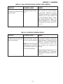
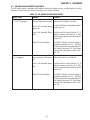
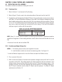
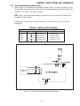
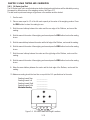
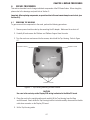
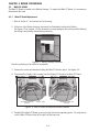
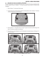
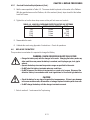
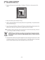
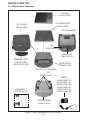
99 Washington Street
Melrose, MA 02176
Phone 781-665-1400
Toll Free 1-800-517-8431
Visit us at www.TestEquipmentDepot.com
EB SERIES SCALES
SERVICE MANUAL
EB SERIES SCALES
SERVICE MANUAL
The information contained in this manual is believed to be accurate at the time of publication,
but Ohaus Corporation assumes no liability arising from the use or misuse of this material.
Reproduction of this material is strictly prohibited.
Material in this manual is subject to change.
© Copyright 2006 Ohaus Corporation, all rights reserved.
® Registered trademark of Ohaus Corporation.
TABLE OF CONTENTS
CHAPTER 1 INTRODUCTION
1.
1.1
1.2
1.3
1.4
Page
Introduction ...................................................................................................... 1-1
Service Facilities ................................................................................................. 1-1
Tools and Equipment .......................................................................................... 1-2
1.2.1 Standard Tools and Test Equipment ............................................................ 1-2
1.2.2 Special Tools........................................................................................... 1-2
Calibration Masses Required ................................................................................ 1-2
Service Strategy .................................................................................................. 1-2
CHAPTER 2 DIAGNOSIS
2.
Diagnosis ...................................................................................................... 2-1
2.1 Scale Setup and Examination ............................................................................... 2-1
2.2 Preliminary Checks ............................................................................................. 2-1
2.3 Troubleshooting Tables ........................................................................................ 2-1
2.4 EB Series Scales Error Code Table ........................................................................ 2-5
CHAPTER 3 SCALE TESTING AND CALIBRATION
3.
Testing and Calibration ........................................................................................ 3-1
3.1 Testing the AC Adapter ......................................................................................... 3-1
3.2 Testing the Membrane Switch ............................................................................... 3-1
3.3 Testing the Load Cell Assembly ............................................................................. 3-2
3.3.1 Resistance Test ........................................................................................ 3-2
3.3.2 Excitation and Output Voltage Test ............................................................. 3-2
3.4 Testing the Main PC Board ................................................................................... 3-4
3.4.1 Main PC Board Voltage Measurements ........................................................ 3-4
3.4.2 Simulator Testing ..................................................................................... 3-5
3.5 Testing the Battery ............................................................................................... 3-6
3.5.1 Precautions for Battery Handling ................................................................ 3-6
3.5.2 Battery Tests ............................................................................................ 3-6
3.6 Performance Tests ............................................................................................... 3-8
3.6.1 Segment Display Test ............................................................................... 3-8
3.6.2 Repeatability Test ..................................................................................... 3-8
3.6.3 Off-Center Load Test ............................................................................... 3-10
3.6.4 Linearity Test ......................................................................................... 3-11
3.7 Specifications ................................................................................................... 3-13
3.8 Calibration .................................................................................................... 3-14
3.8.1 Calibration Points .................................................................................. 3-14
3.8.2 Span Calibration .................................................................................... 3-14
3.9 Scale Settings .................................................................................................. 3-15
i
TABLE OF CONTENTS (Cont.)
CHAPTER 4 REPAIR PROCEDURES
Page
4.
Repair Procedures ............................................................................................... 4-1
4.1 Removing Top Housing ....................................................................................... 4-1
4.2 Replacing the Membrane Switch ........................................................................... 4-2
4.3 Main PC Board ................................................................................................... 4-4
4.3.1 Main PC Board Replacement ..................................................................... 4-4
4.3.2 Display PC Board Replacement .................................................................. 4-7
4.3.3 LCD Replacement ..................................................................................... 4-8
4.4 Replacing the Load Cell Assembly (with frame) ...................................................... 4-9
4.5 Replacing the Load Cell Component .................................................................... 4-11
4.5.1 Overload Protection Stop Adjustment ......................................................... 4-12
4.6 Replacing the Battery ........................................................................................ 4-13
CHAPTER 5 PARTS LISTS
5.
Parts Lists ...................................................................................................... 5-1
5.1 EB Series Scales Components .............................................................................. 5-2
APPENDIX A EB SERVICE MODES/SERVICE CALIBRATION
A.
EB Service Modes ............................................................................................... A-1
A.1 Entering Service Menu ......................................................................................... A-1
A.2 Service Calibration .............................................................................................. A-1
A.3 Scale Configuration ............................................................................................. A-2
ii
CHAPTER 1 INTRODUCTION
1.
INTRODUCTION
This service manual contains instructions for the diagnosis and repair work to be performed by Ohaus
Dealers or Ohaus authorized service centers. Knowledge of the operation of the EB Scale is assumed.
Instruction manuals may be required with this service manual. For complete information on operation,
refer to the Instruction Manual.
This manual covers maintenance on the following:
EB Series Scales, Models EB3, EB6, EB15 and EB30
The contents of this manual are contained in five chapters and an Appendix with Service Mode and Service
Calibration instructions.
Chapter 1 Introduction - Contains information about service facilities, tools, test equipment, test masses,
and service strategy.
Chapter 2 Diagnosis - Contains information on problem verification, scale examination, preliminary
checks and troubleshooting tables.
Chapter 3 Testing - Contains testing procedures, an interconnection diagram, performance tests, battery
tests, specifications and calibration.
Chapter 4 Repair Procedures - Contains detailed repair procedures for all major components.
Chapter 5 Parts Lists - Contains overall views identifying all major serviceable replacement components
with associated parts lists.
Appendix A EB Service Modes/Service Calibration - Contains configuration, capacity and resolution
settings for the EB Series Scales in a service mode.
1.1 SERVICE FACILITIES
The service area should be a stable environment.
The bench area should be clean and should contain an antistatic mat with a personnel-grounding clip
to protect internal circuit boards. The ideal electrical power source for the scales should be a dedicated
line to avoid sudden fluctuations or voltage drops caused by external equipment drawing heavy current.
The service area for the scales should be away from direct sunlight, overhead heating or air conditioning
ducts, magnetic fields such as motors, large transformers or vibrating sources such as machinery.The
power outlet should be grounded for safety. Sufficient space should be provided around the scale as not
to be affected by other equipment. This will ensure that the scale is operated under ideal conditions.
1-1
CHAPTER 1 INTRODUCTION
1.2 TOOLS AND EQUIPMENT
1.2.1 Standard Tools and Test Equipment
The service shop should contain the following equipment:
1. Digital Voltmeter (DVM).
2. Standard Electronics tool kit.
3. Desk magnifier on a stand.
4. Grounding mat and clip.
5. Razor blades.
1.2.2 Special Tools
To service the Ohaus EB Series Scales, the following equipment is recommended:
1. A Load Cell Simulator.
2. AC Adapter, 220 V, 60 Hz (US) Ohaus P/N 80120000
3. AC Adapter, 230 V, 50 Hz (EU) Ohaus P/N 80120001
4. AC Adapter, 230 V, 50 Hz (GB) Ohaus P/N 80120002
5. AC Adapter, 240 V, 50 Hz (AU) Ohaus P/N 80120003
6. AC Adapter, 100 V, 50 Hz (JP) Ohaus P/N 80120004
7. AC Adapter, 230V, 50 Hz (KR) Ohaus P/N 80120025
NOTE: Adapters required for servicing are location dependent.
1.3 CALIBRATION MASSES REQUIRED
The masses required to test the EB Series Scales must meet the requirements of ASTM Class 4 or OIML
Class F2. The mass values are listed in Table 1-1.
TABLE 1-1. CALIBRATION MASSES
MODEL
Calibration
Cal in kg:
Masses Totaling
EB3
3kg
EB6
6kg
EB15
15kg
EB30
30kg
Note: The EB Scales can be calibrated over a wide range, however, it is recommended that the
calibration mass used is at or near the full capacity of the scale for maximum accuracy.
1.4 SERVICE STRATEGY
The repair method for the EB Series Scales is the direct substitution of major assemblies. The available
repair parts are listed in Table 5-1.
The EB Series Scales contains 6 major replaceable assemblies: Top Housing, Membrane Switch, Load
Cell Assembly with Frame, Lead Acid Rechargeable Battery, Display PC Board with LCD and the Main
PC Board.
NOTE: The Load Cell and LCD may also be ordered and replaced separately.
This service manual contains sufficient information to isolate the problem, replace the component, test
and restore the Scale to original factory specifications.
1-2
CHAPTER 2 DIAGNOSIS
2.
DIAGNOSIS
This section contains information needed to properly evaluate the reported problem and diagnose its
cause.
2.1 SCALE SETUP AND EXAMINATION
Set up the scale according to the Instruction manual. Allow the scale to stabilize to room temperature.
Examine the scale for signs of corrosion or physical damage.
2.2 PRELIMINARY CHECKS
Power up the scale using the customer’s ac adapter. In the case where the scale will not power up,
check the ac adapter. Observe and record the error codes and software revision. Record all menu settings
as received.
2.3 TROUBLESHOOTING TABLES
Troubleshooting tables 2-1 through 2-7 identify actual types of problems that could be encountered with
the scale.
The troubleshooting tables refer to an interconnection diagram in Section 3 to assist in locating the
problem.
2-1 SCALE WILL NOT TURN ON WITH AC ADAPTER.
PROBABLE CAUSE
SYMPTOM
Scale will not turn on with AC Adapter defective.
adapter supplied.
REMEDY
Refer to Section 3.1 and check the ac
adapter voltage output. If voltage is
low or nonexistent, replace the ac
adapter. If OK, proceed.
Membrane Switch defective.
Refer to Section 3.2 and test the Membrane Switch. Replace if necessary.
See Repair Procedure 4.2
Main PC Board is defective.
If the scale fails to turn on with a new
Membrane Switch, the Main PC Board
should be tested in accordance with
section 3.4. The Main PC Board if
defective should be replaced. See Repair Procedures 4.3. After repair, proceed with Performance Tests in Section
3.6.
2-1
CHAPTER 2 DIAGNOSIS
TABLE 2-2 SCALE WILL NOT TURN ON USING BATTERY POWER.
SYMPTOM
Scale will not turn on using
battery power.
PROBABLE CAUSE
REMEDY
Battery discharged or defective.
Refer to Section 3.5 and test the battery.
Replace if necessary. See Repair Procedure 4.6.
Wiring harness defective or
battery clips connection
broken.
Refer to section 4.1 and open the scale.
Check voltage at battery contacts first.
Check dc voltage at the battery connector
on the Main PC Board. Voltage should
read approximately 6 Volts dc minimum.
If voltage is not present at the connector,
disconnect the leads from the battery
and make a continuity test between the
connectors on the Harness to the connector on the Main PC Board. Resistance should be 0 ohms for the red lead
and 0 ohms for the black lead. If an open
condition exists, replace wiring and connector as necessary. If OK, proceed.
Membrane Switch defective.
Refer to Section 3.2 and test the Membrane Switch. Replace if necessary. See
Repair Procedure 4.2
Main PC Board is defective.
If the scale fails to turn on with a new
Membrane Switch, the Main PC Board
should be tested in accordance with
Section 3.4. The Main PC Board if defective should be replaced. See Repair
Procedures 4.3. After repair, proceed
with Performance Tests in Section 3.6.
2-2
CHAPTER 2 DIAGNOSIS
TABLE 2-3 SCALE DOES NOT RESPOND TO FRONT PANEL CONTROLS.
SYMPTOM
PROBABLE CAUSE
REMEDY
Scale does not respond to front
panel controls.
Membrane Switch is defective.
Refer to Section 3.2 and test the Membrane switch. Replace if necessary.
See Repair Procedure 4.2. If membrane
switches are OK, refer to Section 3.4
and test the Main PC Board. If defective, replace the Main PC Board. See
Repair Procedures 4.3. After repair,
proceed with Performance Tests in Section 3.6.
TABLE 2-4 NO DISPLAY OR PARTIAL DISPLAY.
SYMPTOM
PROBABLE CAUSE
Display is not on or partial char- Display PC Board is defective or LCD may be defective.
acters are displayed.
NOTE: If the LCD shows signs
of damage such as cracked,
dim or partial characters, the
LCD should be replaced
REMEDY
The Display PC Board is replaced as a
whole assembly. Check procedures in
Tables 2-1, 2-2 and 2-3 first and verify
that other problems do not exist. Then,
refer to Section 3.6.1 and test the LCD
Display.
Replace Display PC Board or LCD. See
Repair Procedures 4.3.2. After repair,
proceed with Performance Tests in Section 3.6.
2-3
CHAPTER 2 DIAGNOSIS
TABLE 2-5 SCALE READING INCORRECT OR UNSTABLE.
SYMPTOM
PROBABLE CAUSE
REMEDY
Scale reads incorrectly.
Needs calibration.
Perform Service Calibration in Appendix A. If calibration fails, refer to Table
2-6.
Scale reading unstable.
Load Cell is damaged.
Test the Load Cell, refer to Section 3.3.
If defective replace, see Section 4.4.
After repair, proceed with Performance
Tests in Section 3.6.
Main PC Board defective.
The Main PC Board should be tested in
accordance with Section 3.4. The Main
PC Board if defective should be replaced. See Repair Procedures 4.3.
After repair, proceed with performance
Tests in Section 3.6.
TABLE 2-6 CANNOT CALIBRATE THE SCALE.
SYMPTOM
PROBABLE CAUSE
Scale can be turned on but will Incorrect weights.
not calibrate.
Load cell assembly defective.
Main PC Board defective
2-4
REMEDY
Verify that proper weights are used.
Test the Load Cell, refer to Section 3.3. If
defective replace, see Section 4.4. After
repair, proceed with Performance Tests
in Section 3.6.
The Main PC Board should be tested in
accordance with Section 3.4. The Main
PC Board if defective should be replaced.
See Repair Procedures 4.3. After repair,
proceed with Performance Tests in Section 3.6.
CHAPTER 2 DIAGNOSIS
2.4 EB SERIES SCALES ERROR CODE TABLE
The EB Series Scales is equipped with software which will display an error condition when it occurs.
Review the listed codes and follow instructions to correct the problem.
TABLE 2-7. EB SERIES SCALES ERROR CODES
REMEDY
ERROR CODE
CAUSE
E1, E2, E3 displayed
The pan is placed incorrectly. Reposition the Platform correctly.
Zero limit exceeded during Ensure the Platform is empty before switching the scale on.
power up.
Load Cell Assembly Defec- Test the Load Cell, refer to Section 3.3. If
defective replace, see Section 4.4. After
tive.
repair, proceed with Performance Tests in
Section 3.6.
Main PC Board defective
--OL-- displayed
The Main PC Board should be tested in
accordance with Section 3.4. The Main
PC Board if defective should be replaced.
See Repair Procedures 4.3. After repair,
proceed with Performance Tests in Section 3.6.
Load exceeds scale capac- Reduce the load on the Platform.
ity.
Load Cell Assembly Defec- Test the Load Cell, refer to Section 3.3. If
defective replace, see Section 4.4. After
tive.
repair, proceed with Performance Tests in
Section 3.6.
Main PC Board defective
2-5
The Main PC Board should be tested in
accordance with Section 3.4. The Main
PC Board if defective should be replaced.
See Repair Procedures 4.3. After repair,
proceed with Performance Tests in Section 3.6.
CHAPTER 2 DIAGNOSIS
2-6
CHAPTER 3 SCALE TESTING AND CALIBRATION
3. TESTING AND CALIBRATION
This section of the manual contains testing procedures of the individual replaceable components and the
scale. Before and after servicing the EB Series Scales, an operational test and various performance tests
should be made to ascertain whether or not the scale meets specifications.
3.1 TESTING THE AC ADAPTER
The AC Adapters are available with different input voltages. Before testing the Adapter, make sure the
Adapter rating agrees with the power source being used. All Adapters are rated with an output of 12 V dc
at 800mA. Adapters can fail by having shorted internal windings producing low voltage output or no
output at all.
1. Plug the AC Adapter in a suitable power source and measure the open circuit voltage on connector
it should be 10 V dc to 16 V dc.
2. Refer to Section 4.1 and remove the Top Housing. Plug the AC Adapter into the scale and
measure the voltage on the battery terminals. Turn the scale on. The voltage should be 6.5 Volts
dc minimum, and 7.5 Volts dc maximum. If the voltage is below or above these readings, replace
the Adapter. This is the actual battery voltage while charging.
3.2 TESTING THE MEMBRANE SWITCH
The Membrane Switch can be tested after removing the Top Housing from the Bottom Housing.
1. Refer to Section 4.1 and remove the Top Housing.
2. Disconnect the Membrane Switch connector from the Display PCB.
3. Refer to Table 3-1. Using an Ohmmeter, measure the resistance between the pins shown in the
table. The readings should be less than 70 Ohms for each button. If continuity is not present or
the resistance is higher than 100 Ohms, the Membrane Switch is defective. Replace the Membrane
Switch. Figure 3-1 illustrates the cable connector and pin locations.
4. Reassemble Top Housing to Bottom Housing.
TABLE 3-1. MEMBRANE SWITCH PIN CONNECTIONS.
PANEL BUTTON
PINS
M+
1 to 2
UNITS
1 to 3
ZERO
1 to 4
TARE
1 to 5
CHECK
1 to 6
COUNT
1 to 7
%
1 to 8
Figure 3-1. Membrane Switch Connector.
3-1
CHAPTER 3 SCALE TESTING AND CALIBRATION
3.3 TESTING THE LOAD CELL ASSEMBLY
This section contains two methods of testing the Load cell.
3.3.1
Resistance Test
1. Refer to Section 4.1 and remove the Top Housing.
2. Refer to Figure 3-2 and record color code and position of the wires from the Load Cell.
3. Unsolder the Load Cell cable from the Main PC Board. Using an Ohmmeter, measure in accordance
with Table 3-2 Load Cell Resistance Readings on the cable. If the resistance readings vary more
than the table readings allow, replace the Load Cell in accordance with the procedure in Section
4.4 or 4.5. This resistance test is useful in determining if the Load Cell has been severely damaged
by a short or open circuit which has occurred on the cell or wiring. If the Load Cell resistance
readings are good, continue with this procedure.
TABLE 3-2 LOAD CELL RESISTANCE READINGS
MEASUREMENT POINTS
READING
Wires 2 & 5
415 + 15 Ohms
Wires 3 & 4
350 + 3 Ohms
NOTE: Wires 2, 3, 4 and 5 must be isolated from chassis ground and shield. Resistance should be
greater than 5 megohms. A lower reading indicates a short in either in the Load Cell cable or the Load
Cell.
4. Reconnect Load cell cable to the Main PCB.
3.3.2
Excitation and Output Voltage Test
NOTES: 1. The following steps involve power applied to the scale.
2. Load Cell solder contacts can be used as measuring points. See Figure 3-2.
1. Insert the Platform Support into the Load Cell Frame and place the Platform on top.
2. Turn on power to the scale.
3. With no load on the Platform, first measure the excitation voltage across point 2 and 5 Load Cell
connection on the PCB. This voltage must be 5.0 Volts dc with the Load cell connected. If the
voltage is lower, disconnect the Load Cell cable from the PC Board and measure again. If the
voltage is 5 Volts dc, the Load Cell is defective and must be replaced. If the voltage remains low,
the PC Board is defective and the Main PC Board must be replaced. For Main PC Board
replacement, see Section 4.3.
3-2
CHAPTER 3 SCALE TESTING AND CALIBRATION
3.3.2 Excitation and Output Voltage Test (Cont.)
4. Refer to Figure 3-2 and measure the voltages on points 3 and 4, +SIG and –SIG points. These
measurements represent the output of the Load Cell. Repeat measurements at 50% and full scale
capacities. See Table 3-3 for typical readings.
NOTE: Table 3-3 indicates typical readings, actual values can vary, but should remain linear
throughout the entire range.
If readings are out of tolerance, replace the Load cell. See Section 4.4 or 4.5 for Load Cell
replacement.
TABLE 3-3. LOAD CELL OUTPUT READINGS.
NOMINAL OUTPUT IN MILLIVOLTS AT 5 VOLTS EXCITATION
CAPACITY
NO LOAD
50%
100%
3 kg
2.7 +1.5 no load + 3.2
no load + 6.4
6 kg
1.9 +1.5 no load + 4.4
no load + 8.8
15 kg
1.2 +1.5 no load + 5.2
no load + 10.3
30kg
0.5 +1.5 no load + 4.9
no load + 10.4
Figure 3-2. EB Series Scales Interconnection Diagram.
3-3
CHAPTER 3 SCALE TESTING AND CALIBRATION
3.4 TESTING THE MAIN PC BOARD
The Main PC Board can be tested by measuring voltages and by using a simulator. The simulator replaces
the Load Cell during testing and is a useful tool for diagnosing problems.
3.4.1 Main PC Board Voltage Measurements
Prior to making the voltage measurements, the battery should have been fully charged and tested.
1. Disconnect power from the scale.
2. Remove the Top housing, refer to Section 4.1 and leave the Membrane Switch connected to the
scale.
3. Disconnect the battery from the Main PC Board.
4. Remove screws and washers holding the Main PC Board and lift the board and lay flat.
5. Connect the AC Adapter to the scale.
6. Refer to Figure 3-2, Interconnection Diagram which illustrates the interconnections to the Main PC
Board and is shown as a top view.
7. Turn the scale on.
8. Using a DVM, measure the excitation voltage across +EXE and -EXE leads it should be 5 volts dc.
This is the excitation voltage for the Load Cell and is regulated. If the voltage is lower, replace the
Main PC Board, refer to Section 4.3 and then proceed with Performance Tests in accordance with
Section 3.6.
9. Measure incoming power from the AC Adapter connector shown in Figure 3-2. The voltage should
read above 6 Volts dc with power on.
10. Connect the battery to the Main PC Board and measure the voltage across Black and Red leads on
the battery connector. The full battery voltage should read a minimum of 6.0 Volts dc. If the voltage
is lower, the battery may require charging or it may be defective. Refer to section 3.5 and test the
battery.
11. Perform simulator testing.
3-4
CHAPTER 3 SCALE TESTING AND CALIBRATION
3.4.2 Simulator Testing
To perform these tests, the use of a Simulator is required. The basic function of a Simulator is to simulate
the output of a full bridge Load Cell allowing the scale to be separated from the Load Cell for the purposes
of troubleshooting and calibration. The Load Cell used in the scale is rated at 2mV/V output with a 5 Volt
excitation voltage applied.
General Load Test
This test checks the Main PC Board circuitry by simulating accurate load cell voltages at 0%, 50% and
100% load capacities.
1. Disconnect power from the scale.
2. Remove the Top housing, refer to Section 4.1 and leave the Membrane Switch connected to the
scale.
3. Disconnect the battery.
4. Unsolder the Load Cell cable from the Main PC Board. Refer to Figure 3-2 for location.
5. With the Simulator set to zero, connect the Simulator test leads to the Main PCB by soldering test
leads in place of the load cell. Make sure connections are correct.
6. Connect a known good AC Adapter to the scale and connect to a power source.
7. Turn on the scale, an error may be displayed. This is normal.
8. Review Table 3-3 and adjust the Simulator to simulate 0% load, 50% load and 100% load for the
rated capacity of the scale. If the resulting readings are unstable, the Main PC Board is defective.
Use the Simulator to calibrate the scale in the next procedure to verify if the Main PC Board is good
or bad.
Calibration Test
This test calibrates the scale using the simulator and can verify that the Main PC Board is functioning
properly or improperly.
1. With the scale on and the Membrane Switch connected, enter calibration mode by pressing and
holding the ZERO switch until CAL is displayed and perform calibration.
2. Follow the scale prompts. When the scale indicates a given weight should be placed on the scale,
set the simulator to an equivalent value based on Table 3-3. For example, when a span value of
3 kg for a 3 kg scale is shown, the simulator should be set to output 9.1mV (2.7 + 6.4).
3-5
CHAPTER 3 SCALE TESTING AND CALIBRATION
Calibration Test (Cont.)
3. Upon completion of calibration, the Main PC Board can be further checked using the Simulator to
simulate various weight values. If simulator settings and weight reading on the scale agree, the
Main PC Board is functional. If the scale readings vary, or do not agree with readings in Table
3-3, the Main PC Board is defective and should be replaced.
4. Remove power from the scale and proceed with Section 4.3 and replace the Main PC Board.
5. After Main PC Board replacement and assembly of the scale, proceed with Performance Tests in
Section 3.6.
3.5 TESTING THE BATTERY
The EB Series Scales contains a rechargable, 6.0 Volt, 5.0 Ampere rated, Lead-Acid Battery.
3.5.1
Precautions for Battery Handling
WARNING DEATH OR SERIOUS INJURY CAN OCCUR
•
•
•
•
Charge the battery only with the charger in the scale. Charging the battery under any
other conditions may cause the battery to overheat, emit hydrogen gas, Leak, ignite
or burst.
Operate the battery at normal temperature range as specified for the scale.
Do NOT short the battery terminals under any conditions.
Do NOT dispose of the battery in incinerators, or crush or try to open. Dispose of the
defective battery in accordance with local regulations for lead-acid type batteries.
CAUTION
•
•
Check the battery for any sign of irregularities in appearance. If there is any damage
to the case such as cracks, deformation or leakage, replace the battery with a new
one.
Do NOT charge the battery with the charger terminals reversed.
3.5.2 Battery Tests
A new battery when installed in the EB Series Scales will provide many years of useful service. The length
of service depends upon the type of use of the scale. If left connected to the AC Adapter all of the time, the
battery receives a small charge when the battery voltage is low, service life can be many years.
The EB Series Scales can be operated for up to 80 hours per charge. Battery life can be maximized by
frequent charging.
1. Upon receipt of the scale, plug in the AC Adapter to a power source and the scale. Allow the battery
to charge. If the battery required a charge, the battery indicator on the front of the LCD display will
indicate charging. Green indicates fully charged, yellow indicates a partial charge and red,
indicates the battery is nearly discharged.
2. Refer to Section 4.1 and remove the Top Housing. Leave the Membrane Switch on the cover
connected to the scale.
3-6
CHAPTER 3 SCALE TESTING AND CALIBRATION
3.5.2
Battery Tests (cont.)
3. With the AC Adapter connected, measure the battery voltage at the battery terminals; the voltage
should be approximately 6 to 7 Volts dc when charging. The voltage should be above 6.0 Volts
dc ten minutes after charging stops.
NOTE: If the scale operates less than 80 hours, charge the battery and turn on the scale and test
how long the scale operates. If the scale operates less than 40 hours with no backlight, the battery
should be replaced. This is 50% capacity.
4. If the battery requires replacement, refer to Section 4.6, charge the new battery overnight and
check scale performance.
3-7
CHAPTER 3 SCALE TESTING AND CALIBRATION
3.6 PERFORMANCE TESTS
Accurate performance of the EB Series Scales is determined by a series of three performance tests,
Repeatability Test, Off-Center Load Test and Linearity Test. These tests are used to evaluate the scale
performance before and after repairs. Each scale tested must meet the requirements specified in each test
as well as the specifications listed in Table 3-4. A scale passing each of these three tests complies with
Ohaus specifications. A segment display test determines if the display is working properly.
3.6.1 Segment Display Test
Connect the AC Adapter into a suitable power source and connect it to the scale. Turn the scale on, all
999999 segments are displayed followed by a countdown of 8's. 7's, 6's and so on until all zeros are
reached briefly followed by a software revision number. This is a segment display test. Figure 3-3
illustrates the starting of the display test.
Figure 3-3. Segment Display.
3.6.2 Repeatability Test
Repeatability is the Standard Deviation of a set of similar weight readings.
Requirements:
To perform this test a single mass must be used for all readings.
The test mass should be approximately 1/2 of the capacity of the scale.
Before starting a repeatability test, set up the scale as follows:
Set Up:
Enter the menu and adjust and record the following setting.
A. Set the Filter level to 1.
B. Set the zero display range to 1d.
C. Set the scale to display the same units as the performance specifications.
Record Settings:
Filter Level Setting =
____________
Auto Zero Tracking Setting =
____________
Displayed Units =
____________
Zero Return =
____________
Mass Used =
____________
3-8
CHAPTER 3 SCALE TESTING AND CALIBRATION
3.6.2
Repeatability Test (Cont.)
Test Procedure:
1. Zero the scale.
2. Using a test mass approximately 1/2 the capacity of the scale, place the mass on the center of
platform. Record the reading on the worksheet provided.
3. Remove the mass from the Platform.
4. Repeat this test starting at step 1 until you record a total of ten readings
Fill in this worksheet with the ten (10) readings.
n
1
2
3
4
5
6
7
8
9
10
Reading
Delta = Reading – Mean
Delta x Delta
n = number of Reading
Mean = Sum of Readings / 10
Delta = Reading – Mean
Standard Deviation = The Square root of (the sum of the (Delta x Delta) / 9)
5. Add the ten readings and divide the total by 10 to find the Mean (average).
Mean = (Reading 1 + Reading 2 + Reading 3 + Reading 4 + Reading 5
+ Reading 6 + Reading 7+ Reading 8 + Reading 9 + Reading 10) / 10
Mean =________
6. Calculate the Delta for each reading and record in the work sheet.
Delta = Reading - Mean
7. Calculate the Delta x Delta for each reading and record in worksheet.
8. Add the ten Delta x Delta values and divide by 9
9. Calculate the Standard Deviation by applying the square root of the result from step 8.
Standard Deviation =___________
3-9
CHAPTER 3 SCALE TESTING AND CALIBRATION
3.6.3 Off-Center Load Test
The Off-Center Load Test is used to determine whether displayed weight values will be affected by moving
the sample to different areas of the weighing surface. See Figure 3-4.
This test must be performed using a single mass or the masses must be stacked.
1. Zero the scale.
2. Place a mass equal to 1/3 of the full-scale capacity in the center of the weighing surface. Press
the ZERO button to return the reading to zero.
3. Slide the mass halfway between the center and the rear edge of the Platform, and record the
reading.
4. Slide the mass to the center of the weighing surface and press the ZERO button to return the reading
to zero.
5. Slide the mass halfway between the center and the left edge of the Platform, and record the reading.
6. Slide the mass to the center of the weighing surface and press the ZERO button to return the reading
to zero.
7. Slide the mass halfway between the center and the right edge of the Platform, and record the
reading.
8. Slide the mass to the center of the weighing surface and press the ZERO button to return the reading
to zero.
9. Move the mass halfway between the center and the front edge of the Platform, and record the
reading.
10. Maximum reading should be less than or equal to the OCL specifications for the scale.
Reading toward Rear
Reading toward Left
Reading toward Right
Reading toward Front
Maximum Reading
____________
____________
____________
____________
____________
Figure 3-4. Off-Center Load Test Weight Locations.
3-10
CHAPTER 3 SCALE TESTING AND CALIBRATION
3.6.4 Linearity Test
The linearity test is used to determine the linearity of the scale throughout its operating range. The results
should be in accordance with the specifications shown above. The reference mass should be approximately 1/8 of the full-capacity of the scale.
NOTE:: The scale must pass the Off-Center Load test and Repeatability Test before the Linearity Test is
performed.
BE CERTAIN TO USE THE SAME REFERENCE MASS THROUGHOUT THE LINEARITY TEST.
1. Press ZERO to zero the display.
2. Place the reference mass on the center of the Platform and record the exact value (all decimal
places) displayed.
3. Remove the reference mass and verify that the display returns to zero. If it does not, disregard the
reading, press ZERO to rezero the display, and take the reading again.
4. Place a mass equal to 1/4 of the full scale capacity on the Platform and press ZERO.
5. Add the reference mass to the center of the Platform and record the exact value displayed.
6. Remove the reference mass and verify that the display returns to zero. If it does not, disregard the
reading, press ZERO to rezero the display, and take the reading again.
7. Place a mass equal to 1/2 of the full-scale capacity on the Platform and press ZERO.
8. Add the reference mass to the center of the Platform and record the exact value displayed.
9. Remove the reference mass and verify that the display returns to zero. If it does not, disregard the
reading, press ZERO to rezero the display, and take the reading again.
10. Place a mass equal to 3/4 of the full scale capacity on the Platform and press ZERO.
11. Add the reference mass to the center of the Platform and record the exact value displayed.
12 Remove the reference mass and verify that the display returns to zero. If it does not, disregard the
reading, press ZERO to rezero the display, and take the reading again.
13. Calculate the weight differences between the reading as shown in the recorded readings.
14. The Maximum difference should be less than or equal to the Linearity specification for the
scale.
3-11
CHAPTER 3 SCALE TESTING AND CALIBRATION
3.6.4
Linearity Test (cont.)
Record Readings
Reading 1 reference weight added to zero
________________
Reading 2 reference weight added at 1/4 full-scale capacity ________________
Reading 3 reference weight added at 1/2 full-scale capacity ________________
Reading 4 reference weight added at 3/4 full-scale capacity ________________
Calculate Differences
Reading 1 – [(Reading 1 + Reading 2) / 2] =
________________
Reading 2 – [(Reading 2 + Reading 3) / 2] =
________________
Reading 3 – [(Reading 3 + Reading 4) / 2] =
________________
Maximum Difference
_____________
3-12
CHAPTER 3 SCALE TESTING AND CALIBRATION
3.7 SPECIFICATIONS
TABLE 3-4. EB SCALE SPECIFICATIONS.
Model
Capacity x Readability
Maximum Displayed Resolution
Construction
Weighing Units
Application Modes
Display
EB3
EB6
3 kg x 0.0001 kg
EB15
6 kg x 0.0002 kg
15 kg x 0.0005 kg
30 kg x 0.001 kg
3000 g x 0.1 g
6000 g x 0.2 g
15000 g x 0.5 g
30000 g x 1 g
6.6 lb x 0.0002 lb
13 lb x 0.0005 lb
33 lb x 0.001 lb
66 lb x 0.002 lb
105 x 0.005 oz
208 x 0.01 oz
528 x 0.02 oz
1,056 x 0.05 oz
1:30000
1:30000
1:30000
kg, g, lb, oz
Weighing, Counting, Hi-Lo Check-weigh/count, Percent, Accumulation
1-Window backlit LCD display , 25.4 mm/1" High, 6-digit, 7-segment
Stability, Center of Zero, Gross, Tare, battery status, Hi-Ok-Lo, Units
Keyboard
7 Function menbrane switch: M+, Units, Zero, Tare, Check, Count, %
Tare Range
4% of Full Scale Capacity
Full Capacity by Subtraction (except EB15, up to 10kg only)
Stabilization Time
< 2 seconds
Operating Temperature
0° to 40°C
Humidity Range
Power
<90% relative humidity, non-condensing
AC Adapter 12V DC / 800mA
Internal rechargeable lead acid battery
Battery Life
Calibration
Shipping Protection
Safe Overload Capacity
Platform Size
Scale Dimensions W x H x D
Shipping Dimensions W x H x D
Net Weight
Shipping Weight
Other Features
1:30000
Stainless steel platform, plastic housing
Display Indicators
Zero Range
EB30
80 hours continuous use with 12 hour recharge time
Automatic external with kg/g mass, factory calibration recovery
Shipping screw to avoid damage to sensitive components
120% of capacity
294 x 226 mm / 11.6 x 8.9 in.
325 x 330.5 x 114 mm / 12.8 x 13 x 4.5 in.
440 x 360 x 160 mm / 17.3 x 14.2 x 6.3 in.
4.2 kg / 9.3 lb
5.3 kg / 11.7 lb
Auto-Zero Tracking, Filtering Level
3-13
CHAPTER 3 SCALE TESTING AND CALIBRATION
3.8 CALIBRATION
Calibration – The EB Series’ calibration can be calibrated using full scale capacity as the best method
for the most accurate results, this is referred to as span calibration.
Calibration Weights – Before beginning calibration, make sure that the required calibration weights are
available. The model-specific calibration points are listed in the Table 3-5.
3.8.1
Calibration Points
TABLE 3-5. CALIBRATION POINTS.
Model
EB3
Calibration Unit
kg
lb
Span Calibration
3 kg
6 lb
EB6
Kg
lb
6 kg
15 lb
EB15
Kg
lb
kg
lb
15 kg
30 lb
30 kg
60 lb
EB30
NOTES: 1. Calibration Units kg or lb are selected in the (Setup mode) sub-menu.
2. ASTM Class 4 or OIML Class F2 weights are required for calibration.
3.8.2
Span Calibration
1. Enter calibration by a long press of the ZERO and COUNT at the same time to initiate calibration.
2. The required calibration weight is displayed (ex. 3000g for a 3kg model). At this time, a different
calibration weight value can be entered by pressing
.
3. Place the corresponding calibration weight on the Platform. the display flashes until the actual
weight is registered and the calibration process ends (the scale restarts) then remove the weight.
NOTE: 1. Different values of calibration masses can be used on the EB scale, however, it is recommended
that the calibration mass used is close to or matches the maximum capacity of the scale for
best accuracy.
2. The calibration procedure can be canceled at any time by turning the scale off.
3. If needed, the factory default calibration value can be recovered. As the scale is turned on, press
TARE and COUNT at the same time during power-on sequence. The power-on sequence will
re-cycle and the scale will re-initiate with the default calibration.
3-14
CHAPTER 3 SCALE TESTING AND CALIBRATION
3.9 SCALE SETTINGS
The EB scale contains four user-selectable scale settings (Setup mode). These are as follows:
Scale Increment, Backlight, Zero Tracking Range and Filtering. A description of each setting is explained
below.
1. To enter the Setup mode, press and then release COUNT and M+ at the same time to enter
into the user-selectable scale settings.
2. In the Setup mode, press
to step through available settings.
3. Press Enter to accept the displayed setting and proceed to the next parameter.
4. Press Exit to proceed to the next parameter without saving any changes.
inC 01
(model dependent settings)
EL AU
AC 2d
AU
on
OFF
0.5d
1d
2d
4d
(d=scale division)
FiL 1
0
1
2
3
(Levels)
inC 01
Scale increment - Sets the displayed scale increment (also known as readability
or graduation). Selectable setup values will be model dependent and are
equivalent to within 30,000 to 3,000 scale divisions.
EL AU
Backlight - Sets the activation mode of the backlight.
The following settings are available: AU (Auto-on with items greater than 9d
placed on the Platform or any button is pressed; turns off after 5 seconds of
inactivity), on, oFF.
AC 2d
Zero Display Range - Sets the range in which the Zero reading is maintained.
The following settings are available: 0.5d, 1d, 2d, 4d (d= scale division).
FiL 1
Filtering - Sets the level in which the Stable indication turns on; the higher the
setting, the faster the stabilization time.
The following settings are available: 0, 1, 2, 3 (levels).
3-15
CHAPTER 3 SCALE TESTING AND CALIBRATION
3-16
CHAPTER 4 REPAIR PROCEDURES
4.
REPAIR PROCEDURES
This section describes how to change individual components of the EB Series Scales. When doing this,
please refer to the drawings and parts lists in Section 5.
Important: After replacing components, an operational test of the scale must always be carried out, (see
Section 3.6).
4.1 REMOVING TOP HOUSING
To gain access to the components in the scale, perform the following procedures.
1. Remove power from the scale by disconnecting the AC adapter. Make sure the scale is off.
2. Carefully lift and remove the Platform and Platform Support from the scale.
3. Turn the scale over and remove the five screws, which hold the Top Housing. Refer to Figure
4-1.
RETAINING SCREW
RETAINING SCREW
RETAINING SCREWS
Figure 4-1. Top Housing Retaining Screws Location.
CAUTION
Use care in the next step as the Display PCB wiring is attached to the Main PC board.
4. Place the scale in the upright position and carefully lift the Top Housing from the Base
and tilt forward. Reach under the Top Housing from the front and carefully disconnect the flexible
cable from connector on the Display PC board.
5. Set the Top Housing aside.
4-1
CHAPTER 4 REPAIR PROCEDURES
4.2 REPLACING THE MEMBRANE SWITCH
The membrane switch is affixed to the Top Housing of the scale. To replace the Membrane Switch, the scale
must be disassembled to gain access to the switch connections.
1. Refer to Section 4.1 and remove Top Housing.
CAUTION
Use care in the next step as the Display PCB wiring is attached to the PC board.
2. Place the scale in the upright position and carefully lift the Top Housing from the Base Housing.
Figure 4-2. Removing the Top Housing.
3. Carefully disconnect the ribbon cable from connector on the Display PC board. See Figure
4-3.
Figure 4-3. Disconnecting the Ribbon Cable.
4-2
CHAPTER 4 REPAIR PROCEDURES
4.2
REPLACING THE MEMBRANE SWITCH (Cont.)
4. Disconnect the Membrane Switch Cable from the Display PCB as shown in Figure 4-4.
Figure 4-4. Disconnecting the Membrane Switch Cable.
5. On the Top Housing, lift up the defective Membrane Switch (if necessary carefully prying it up with
a knife) and gently peel it off the Top Housing.
6. Carefully clean the Top Housing membrane switch area (removing all traces of adhesive).
The best method is to use a flat razor blade.
7. Insert the cable from the new Membrane Switch through the hole in the Top Housing. Peel
off the protective film from the new Membrane Switch and carefully align and affix to the Top
Housing.
8. Press the Membrane Switch down uniformly. Using your fingers with a cloth, roll from the
center of the Membrane Switch outward towards the edges to remove any air bubbles that may
be trapped.
9. Position the Top Housing in place over the Bottom Housing and connect the flexible cable from the
Main PC Board to Display PC Board.
10. Reassemble the scale by replacing the five screws at the bottom of the scale which secure
the Top housing.
11. Replace the Platform Support and Platform on top of the scale.
4-3
CHAPTER 4 REPAIR PROCEDURES
4.3 MAIN PC BOARD
The Main PC Board is located in the Bottom Housing. To replace the Main PC Board, it is necessary to
disassemble the scale.
4.3.1
Main PC Board Replacement
1. Refer to Section 4.1 and remove the Top Housing.
2. At the rear of the Bottom Housing, disconnect the Red battery lead from the Battery.
See Figure 4-5 for location. This is necessary to prevent damge to the circuitry and the Battery if
the wiring is accidentally shorted during servicing.
Figure 4-5. Battery Terminal Connector.
Note the positioning of the cable for reassembly.
3. Remove the screws and washers holding the Main PC Board in place. See Figure 4-6.
4. Disconnect the Display Cable coming from the Display PC Board on the Main PC Board.
MOUNTING SCREW AND
WASHER
DISPLAY CABLE
MOUNTING SCREW AND
WASHER
Figure 4-6. Main PC Board Screws and Washers Removal.
5. Carefully lift the Main PC Board up and out of the slots in the supporting posts. You may have to
rock the Main PC Board from left to right to lift the board out.
4-4
4.3.1
CHAPTER 4 REPAIR PROCEDURES
Main PC Board Replacement (Cont.)
6. Remove the Battery connector plug from the Main PC Board and the connector that connects
to the On/Off Switch. See Figure 4-7.
LOAD CELL WIRING
BATTERY CONNECTOR
ON/OFF SWITCH CONNECTOR
Figure 4-7. Disconnecting Battery and On/Off Switch Connectors from Main PC Board.
7. Unsolder the Load Cell wiring from the Main PC Board. Note the position and color coding of the
wires on the Main PC Board. These will have to be soldered on the new PC Board in the same
positions.
8. On the replacement Main PC Board, install the Battery and Switch connectors.
9. Refer to Figure 3-2 and solder the Load Cell wiring to the replacement Main PC Board. Make sure
that the color coded wiring is installed in the correct locations.
10. Connect the Display Cable to the Main PC Board connector. See Figure 4-8.
CAUTION: THE DISPLAY CABLE CONNECTOR MUST BE CORRECTLY INSTALLED WITH THE TAB FACING UP.
DISPLAY CABLE
DISPLAY CABLE CONNECTOR
CONNECTOR TAB
Figure 4-8. Installing Display Cable to Main PC Board.
4-5
MAIN PC BOARD
CHAPTER 4 REPAIR PROCEDURES
4.3.1
Main PC Board Replacement (Cont.)
11. Install the Main PC Board into position in the slots on the Bottom Housing and secure with the
screws and washers previously removed.
12. Connect the Battery connector to the Battery.
NOTE: When a replacement Main PC Board is installed, the scale must be put into a service mode first
to enter parameters such as capacity and readability. Calibration must also be performed, see
Appendix A.
13. Refer to Figure 4-9 and move the Main PC Board Jumper from normal to service position.
NORMAL
SERVICE
Figure 4-9. Main PC Board Jumper Positions.
14. Position the Top Housing in place over the scale temporarily and install the Platform Support and
Platform in place.
15. Set the capacity and readability, see Appendix A.
16. Calibrate the scale according to the Instructions in Appendix A. After calibration, turn off the scale
and replace the jumper into the normal position.
17. Reassemble the scale and replace the Platform Support and Platform on top of the scale.
18. Turn the scale on. It will go through all the self-testing and operate normally.
19. After repair, initiate Performance Tests, see Section 3.6.
4-6
CHAPTER 4 REPAIR PROCEDURES
4.3.2
Display PC Board Replacement
1. Refer to Section 4.1 and remove the Top Housing.
2. Disconnect the Ribbon Cable from the Display PC board. See Figure 4-10.
Figure 4-10. Disconnecting the Ribbon Cable.
3. Disconnect the Membrane Switch Cable from the Display PC Board. See Figure 4-11.
Figure 4-11. Disconnecting the Membrane Switch Cable from the Display PC Board.
4. Remove the six screws that hold the Display PC Board to the Top Housing. See Figure 4-12.
Figure 4-12. Removing Screws from the Display PC Board.
5. Examine the replacement Display PC board and remove all protective plastic film that may be
covering the LCD display.
4-7
CHAPTER 4 REPAIR PROCEDURES
4.3.2
Display PC Board Replacement (Cont.)
6. Install the replacement Display PC board with the screws previously removed.
7. Connect the Membrane Switch Cable from the Top Housing to the Display PC Board and the Ribbon
Cable from the Main PC Board to the Display PC Board.
8. Reassemble and test the scale according to Performance Tests in section 3.6.
4.3.3 LCD Replacement
This procedure is performed when an LCD shows signs of visible damage such as a cracked glass or partial
display and the scale operates normally in all other functions.
NOTE: This procedure is very difficult and should not be attempted unless you have the proper tools.
1. Perform steps 1 through 4 of Section 4.3.2.
2. Carefully unsolder all contacts of the defective LCD and remove the LCD. All solder holes on the
Display PC board must clean and open to accept the pins of the LCD.
3. Solder all connections, check the Display PC Board and make sure that solder has not spilled over
to other connections. Remove any protective film from the LCD and replace the LCD.
4. Continue with steps 6 through 8 of Section 4.3.2.
4-8
CHAPTER 4 REPAIR PROCEDURES
4.4 REPLACING THE LOAD CELL ASSEMBLY (WITH FRAME)
The Load Cell Assembly is centrally located inside the scale. The Load Cell is factory assembled and the
overload protection stops are installed. The overload protection stops should be checked before
installation.
1. Refer to Section 4.1 and remove Top Housing.
2. Turn the scale over and remove the four feet by unscrewing them counter-clockwise. The feet are
actually screwed into the Load Cell Frame.
Figure 4-13. Bottom of Scale Feet.
3. Refer to Section 4.3.1 and perform steps 1 through 7 to gain access to the Load Cell wiring on the
Main PC Board and unsolder the connections.
4. Remove the four screws holding the Load Cell Assembly to the bottom housing. See Figure 4-14
for screw locations.
Figure 4-14. Load Cell Retaining Screw Locations.
4-9
CHAPTER 4 REPAIR PROCEDURES
4.4
REPLACING THE LOAD CELL ASSEMBLY (WITH FRAME) (Cont.)
5. Refer to Section 4.5.1 and check overload stops on the new assembly.
6. Lift the Load Cell Assembly out of the Bottom Housing and replace with the new one. Install screws.
7. Refer to Figure 3-2 and the label on the replacement Load Cell.
8. Solder the Load Cell wiring to the Main PC Board. Make sure that the color coded wiring is installed
in the correct locations.
9. Reconnect the battery and power connectors to the Main PC Board and connect the battery terminal
wiring to the battery.
10. Connect the Display Cable from the Display PC Board to the Main PC Board.
11. Install the Main PC Board into position in the slots on the Bottom Housing and secure with the
screws and washers previously removed.
12. Refer to Figure 4-15 and move the Main PC Board Jumper from normal to service position.
NORMAL
SERVICE
Figure 4-15. Main PC Board Jumper Positions.
13. Position the Top Housing in place over the scale temporarily and install the Platform Support and
Platform in place.
14. Calibrate the scale according to the Instructions in Appendix A. After calibration, replace the
jumper into the normal position.
15. Reassemble the scale and replace the Platform Support and Platform on top of the scale.
16. Turn the scale off then on. It will go through all the self-testing. When self-testing is completed,
the scale should work nomally.
17. After repair, perform Performance Tests, see Section 3.6.
4-10
CHAPTER 4 REPAIR PROCEDURES
4.5 REPLACING THE LOAD CELL COMPONENT
This procedure is used when it is desired to keep the existing Load Cell Frame and replace only the Load
Cell. The Load Cell Assembly is centrally located inside the scale. When the new Load Cell is mounted
to the existing Frame, the Overload Protection Stops must be adjusted.
1. Refer to Section 4.1 and remove Top Housing.
2. Refer to Section 4.4 and perform steps 1 through 4. The Load Cell and Frame can now be removed.
Make sure the Load Cell Cable in the Bottom Housing can be removed by cutting the tie wrap holding
the battery wires together with the Load Cell cable.
3. Remove the Load Cell, by unscrewing two bolts on the top of the Load Cell and two bolts on the
bottom of the Load Cell. See Figure 4-16.
MOUNTING BOLTS
MOUNTING BOLTS
TOP OF LOAD CELL
BOTTOM OF LOAD CELL
Figure 4-16. Load Cell Mounting Bolt Locations.
4. Place the replacement Load Cell on the Bottom Load Cell Frame into position and install the two
bolts previously removed. DO NOT TIGHTEN.
5. Postion the Top load Cell Frame on top of the Load Cell and install the two bolts previously
removed. DO NOT TIGHTEN.
TABLE 4-1. LOAD CELL SCREW TORQUE INFORMATION.
CAPACITY
TORQUE
3 kg
7 N.m / 62 in. lb
6 kg
10 N.m / 88 in. lb
15 kg
10 N.m / 88 in. lb
30kg
10 N.m / 88 in. lb
6. Align Top and Bottom Frames and tighten screws as indicated. Recheck alignment.
4-11
CHAPTER 4 REPAIR PROCEDURES
4.5
REPLACING THE LOAD CELL COMPONENT (Cont.)
7. Position the Load Cell and Frame in the Bottom Housing and install the four retaining screws
through the Frame into the Bottom Housing. See Figure 4-17.
RETAINING SCREW
TIE WRAP
Figure 4-17. Load Cell Frame Mounting Bolt Locations.
8. Install a cable clamp holding the Load Cell cable on the bottom of the Frame assembly to the other
wires in the Housing.
9. Proceed to section 4.5.1 and set the overload stops.
4.5.1 Overload Protection Stop Adjustment
When a Load Cell has been replaced in the existing Load Cell frame, the Overload Protection Stops must
be set before calibrating or testing the scale. This will require the use of mm feeler gauges ranging from
0.6 to 1.6 mm and masses. See Table 4-2.
1. At each Overload Stop Protection location, insert the proper feeler gauge as specified in Table 4-2.
2. With the correct feeler gauge positioned in the first Overload Protection Stop, press down on the
Frame and see if there is movement of the frame. Adjust the Overload Protection Stop until there
is no movement with the feeler gauge inserted. The resulting gap should be the thickness of the
feeler gauge. Do all four stops and recheck until settings are correct.
ADJUSTING SCREW
ADJUSTING SCREW
LOCKING NUT
LOCKING NUT
GAP
Figure 4-18. Overload Stop Locations.
4-12
CHAPTER 4 REPAIR PROCEDURES
4.5.1
Overload Protection Stop Adjustment (Cont.)
3. Add the mass specified in Table 4-2. The mass should be placed on the center of the Platform.
With the specified mass on the Platform, all of the overload (down) stops should hit the bottom
Load Cell Frame.
4. Tighten the nut on the down stop screws so they will not move and recheck.
TABLE 4-2. LOAD CELL OVERLOAD PROTECTION STOP GAP SETTINGS
SCALE CAPACITY
OVERLOAD GAP SETTING
MASS
3 kg
0.6mm
4.5kg
6 kg
0.8mm
9kg
15 kg
1.0mm
22.5kg
30kg
1.6mm
45kg
5. Reassemble the scale.
6. Calibrate the scale using Appendix A instructions. Check all operations.
4.6 REPLACING THE BATTERY
This procedure is used when it is required to change the Battery.
WARNING: DEATH OR SERIOUS INJURY CAN OCCUR
• Charge the battery only with the charger in the scale. Charging the battery under any
other conditions may cause the battery to overheat, emit hydrogen gas, leak, ignite
or burst.
• Operate the battery at normal temperature range as specified for the scale.
• Do NOT short the battery terminals under any conditions.
• Do NOT dispose of the battery in incinerators, or crush or try to open. Dispose of the
defective battery in accordance with local regulations for lead-acid type batteries.
CAUTION
• Check the battery for any sign of irregularities in appearance. If there is any damage
to the case such as cracks, deformation or leakage, replace the battery with a new one.
• Do NOT charge the battery with the charger terminals reversed.
1. Refer to section 4.1 and remove the Top housing.
4-13
CHAPTER 4 REPAIR PROCEDURES
4.6
REPLACING THE BATTERY (Cont.)
2. Disconnect the two wires from the battery. See Figure 4-19 which is a close-up view of the
battery.
Figure 4-19. Battery Connections.
3. Remove the Battery from the Bottom Housing.
4. Install a replacement Battery into the same position as the original Battery. The positive terminal
(Red) should be facing up.
5. Connect the wires to the Battery. Make sure the Red wire is attached to the positive terminal on the
Battery and the Black wire is attached to the negative terminal on the Battery.
Note: The Battery is held in place by the Top Housing that has a cutout and foam backing. When the
Top Housing is installed, the Battery is held in place.
CAUTION: Dispose of the Battery according to local regulations for hazardous materials.
Do not incinerate, crush or throw out in regular garbage containers. Battery contains an
acid solution.
6. Reassemble the scale and connect the ac adapter to the scale and plug into a power source. Allow
the battery to charge for at least 12 hours with the scale off. A new battery requires a long charge
period to obtain maximum service when operating the scale for the first time.
4-14
CHAPTER 5 PARTS LISTS
5. PARTS LISTS
This section of the manual contains exploded views, and parts lists for the EB Series Scales. The
exploded view drawings identify the replaceable parts.
NOTE:
In all cases where a part is replaced, the scale must be
thoroughly checked after the replacement is made.
The scale MUST meet the parameters of all applicable
specifications in this manual.
If further technical information is needed, in the United States call toll-free 1-800-526-0659 between
8.00 a.m. and 4.00 p.m. EST. An Ohaus factory service technician will be available to provide
assistance. Outside the U.S.A., please visit our site www.Ohaus.com to locate the nearest Ohaus
office.
Ohaus Corporation
19A Chapin Road
P.O. Box 2033
Pine Brook, NJ 07058, USA
Tel: (973) 377-9000
Fax: (973) 944-7177
5-1
CHAPTER 5 PARTS LISTS
5.1 EB Series Scales Components
PLATFORM
(P/N 80120009)
PLATFORM SUPPORT
(P/N 80120007)
TOP HOUSING
(P/N 80104205)
TOP HOUSING OPEN
LCD
(P/N 80104203)
DISPLAY PCB
(P/N 80104191)
MEMBRANE SWITCH
(P/N 80251386)
(P/N 80251391 EBJP)
FRONT OVERLAY
(P/N 80251385)
EB SCALE FULLY ASSEMBLED
FEET
(P/N 80120032) - 1 Pc
ADAPTER
(P/N 80120000, US)
(P/N 80120001, EU)
(P/N 80120002, GB)
(P/N 80120003, AU)
(P/N 80120004, JP)
(P/N 80120025, KR)
HARDWARE KIT
(P/N 80120031)
BOTTOM HOUSING
(P/N 80120024)
Figure 5-1. Major Components of EB Series Scales.
5-2
CHAPTER 5 PARTS LISTS
5.1 EB Series Scales Components (Cont.)
LOADCELL
(P/N 80120013, EC3)
(P/N 80120014, EC6)
(P/N 80120015, EC15)
(P/N 80120016, EC30)
BATTERY
(P/N 80120026)
LOADCELL ASSEMBLY
(P/N 80120017, EC3)
(P/N 80120018, EC6)
(P/N 80120019 EC15)
(P/N 80120020, EC30)
LOAD CELL TOP FRAME
(P/N 80120039)
LOAD CELL
BOTTOM FRAME
(P/N 80120040)
MAIN PCB
(P/N 80104190)
POWER ON/OFF
SWITCH
(P/N 80120021)
DISPLAY CABLE
(P/N 80120022)
BOTTOM HOUSING OPEN
BUBBLE LEVEL
(P/N 80120042)
Figure 5-2. Components in Bottom Housing of EB Series Scales.
5-3
CHAPTER 5 PARTS LISTS
TABLE 5-1. EB SERIES SCALES PARTS LIST.
PART NO.
80120000
80120001
80120002
80120003
80120004
80251386
80251391
80120007
80120009
80120010
80104203
80104204
80120013
80120014
80120015
80120016
80120017
80120018
80120019
80120020
80120021
80120022
80104205
80120024
80120025
80120026
80120027
80120028
80104190
80104191
80120031
80120032
80120039
80120040
80120042
80251385
DESCRIPTION
Adapter, US, 120V,
Adapter, EU, 230V,
Adapter, GB, 230V,
Adapter, AU, 240V,
Adapter, JP, 100V,
Switch, Membrane
Switch, Membrane, EBJP
Platform support
Platform, Stainless Steel
Overlay, Back
LCD, 1pc.
Backlight, 1pc.
Loadcell, EC3
Loadcell, EC6
Loadcell, EC15
Loadcell, EC30
Loadcell assembly, EC3
Loadcell assembly, EC6
Loadcell assembly, EC15
Loadcell assembly, EC30
Power switch assembly
Cable, Display PCB
Housing, Top
Housing, Bottom
Adapter, KR, 230V
Battery
Battery wire harness
Cover, In-use
PCB, Main
PCB, Display
Kit, hardware
Foot
Frame, Loadcell, Top
Frame, Loadcell, Bottom
Level, Bubble
Overlay, Front
5-4
APPENDIX A EB SERVICE MODES/SERVICE CALIBRATION
A. EB SERVICE MODES
This Appendix describes the Service menu and sub-menus, which allow authorized service personnel to
configure the EB scale. Configuration settings include setting the capacity and resolution and setting the
decimal point position.
A.1
ENTERING THE SERVICE MENU
1. Open the scale housing and move the jumper to the service position as shown in
Figure A-1.
NORMAL
SERVICE
Figure A-1. Main PC Board Jumper Positions.
2. Turn on the scale and press and hold the TARE, COUNT and ZERO buttons simultaneously
while the display is counting down, release when either 0.0 or xx000 is displayed.
Notes: 1. If the PCB has calibration data, the display will indicate 0.0. When 0.0 is displayed,
proceed to paragraph A.2 Calibration.
2. If a new PCB has been installed, the display will indicate the resolution of the scale
xx000 where xx= 12, 15, 30, 60 or 75. When xx000 is displayed, proceed to
paragraph A.3 Scale Configuration.
A.2
SERVICE CALIBRATION
Service calibration utilizes a three point calibration technique where calibration weights of 1/3, 2/3 and
full capacity are used. If after performing paragraph A.1 and 0.0 is displayed, proceed as follows:
1. Lightly depress the Platform and wait until the display shows the first calibration weight to add
1/3 of (capacity).
2. Add the displayed weight and wait until the display shows the second (total) weight to add
(2/3 of capacity).
A-1
APPENDIX A EB SERVICE MODES/SERVICE CALIBRATION
A.2
SERVICE CALIBRATION (Cont.)
3. Add the displayed weight and wait until the display shows the third weight to add (full capacity).
4. After accepting the weight, the scale will restart the scale check process. Remove the weight
while the self-check is occurring.
5. The display will show 0.0. Turn off the scale.
6. Refer to Figure A-1 and return the jumper to the normal position.
A.3
SCALE CONFIGURATION
1. After performing paragraph A.1 and xx000 is displayed, press COUNT button to step through
the available settings for points of resolution as shown on table A-1, disregard any settings
not shown in the table.
TABLE A-1. SCALE RESOLUTION SETTINGS.
MODEL
3
6
15
30
RESOLUTION
30000
60000
15000
30000
CAPACITY
3000.0
6000.0
15000
30000
2. When the correct value is displayed, press the TARE button to accept.
3. The display will now show the capacity, press the COUNT button to step through the available
settings.
4. When the correct value is shown, press the TARE button to accept. The display will now show
0.0.
5. After the configuration of the scale has been done, it must be calibrated, perform procedure
in paragraph A.2.
A-2
*80251392*
PN 80251392 A SERVICE MANUAL - EB SERIES SCALES
Test Equipment Depot - 800.517.8431 - 99 Washington Street Melrose, MA 02176 - TestEquipmentDepot.com