1
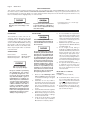
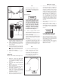
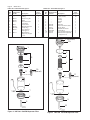
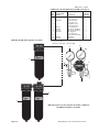
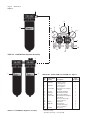
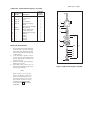
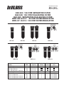
SERVICE BULLETIN
SB-6-148-L
Replaces SB-6-148-K
HAF-503 150 CFM SEPARATOR FILTER
HAF-508 150 CFM COALESCING FILTER
HAF-509 SEPARATOR-COALESCING FILTER
HFRL-509 & 512 80 CFM FILTER-REGULATOR
HFRL-511 & 513 120 CFM FILTER-REGULATOR
HAF-503
HAF-508
HFRL-512
Max.
Models
CFM
Filters Only
HAF-503 Separator
150
HAF-508 Coalescer
150
HAF-509 Separator- Coalescer
150
Filter - Regulators
HFRL-509 Separator
80+
HFRL-511 Separator
120+
HFRL-512 Separator-Coalescer
80+
HFRL-513 Separator-Coalescer
120+
HAF-509
HFRL-509
HFRL-511
Filtering
Capacity
HFRL-513
Regulated
Outlets
Main
Outlet Thread
Outlet
Size
5 micron
.01 micron
.01 micron
5 micron
5 micron
.01 micron
.01 micron
2
4
2
4
1
1
1
1
1/4" NPS(M)
1/4" NPS(M)
1/4" NPS(M)
1/4" NPS(M)
Page 2
SB-6-148-L
SAFETY PRECAUTIONS
This manual contains important information that ALL users should know and understand BEFORE using the equipment. This
information relates to USER SAFETY and PREVENTING EQUIPMENT PROBLEMS. To help you recognize this information, we use
the following terms to draw your attention to certain equipment labels and portions of this manual. Pay special attention to any
label or information that is highlighted by one of these terms:
Note
Important information that tells how
to prevent damage to equipment, or
how to avoid a situation that may
cause minor injury.
Important information - a hazard
that may cause serious injury or loss
of life.
DESCRIPTION
INSTALLATION
The CleanAir air control units are designed to remove dirt, pipe scale, and
most liquid aerosol. The HAF-503 150 CFM
separator filter includes a 5 micron filter
element. The HAF-508 150 CFM coalescing
filter includes a .01 micron filter element.
Both filters include an automatic drain
which expels liquids which accumulate
in the filter bowl.
Certain solvents, paints and chemicals may attack plastic bowl and can
cause bowl failure. Do not use near
these materials.
Do not place unit in service without
metal bowl guard installed. Plastic
bowl units are sold only with metal
bowl guards. To minimize the danger of flying fragments in the event
of plastic bowl failure, guard must
not be removed. If the unit is in service without the metal bowl guard
installed, manufacturer's warranties are void and the manufacturer
assumes no responsibility
for any
resulting loss. If unit has been in
service and does not have a metal
bowl guard, order one and install
before placing back in service.
SPECIFICATIONS
Filter Port Sizes
3/4" NPT(F)
Maximum Inlet Pressure 150 PSIG (10.3 Bar)
Maximum Temperature 150° F (65.6° C)
Risk of personal injury.
Risk of property damage.
Except as otherwise specified by
the manufacturer, this product
is specifically designed for compressed air service and use with
any other fluid (liquid or gas) is a
misapplication. For example, use
with or injection of certain hazardous gases in the system (such as
ozygen or liquid petroleum gas)
could be harmful to the unit or
result in a combustible condition
that may cause fire or explosion.
Manufacturer’s warranties are void
in the event of misapplication and
manufacturer assumes no responsibility for any resulting loss.
Be sure to read all "Warnings", "Cautions" and "Notes" in this manual and
on unit before installing or using this
equipment.
2. Install filter as close as possible to
point where air is being used. Install
main air shut-off valve and standard
pipe union (supplied by user) upstream of filter to allow maintenance
to unit.
3. Install unit with air flow through filter
in direction of arrow on top of unit.
4. Minimum 3/4" piping is recommended. Avoid using fittings, couplings,
etc. that restrict air flow.
5. A 3/4" street elbow will be needed
to allow vertical pipe installation.
Mount filter in a vertical position.
1.
Information that you should pay
special attention to.
6.
Do not install filter in an application
where the pressure drop will exceed
20 psi. For example, a quick opening
valve located upstream from the filter
could cause a momentary pressure
drop in excess of 20 psi.
7. Maximum inlet pressure and operating temperature is 150 PSIG (10.3 bar)
and 150° F (65.6° C).
8. A 6 ft. length of vinyl tubing is
shipped loose with the unit. Slide over
automatic drain which protrudes from
bottom of bowl. Place other end of
vinyl tubing into appropriate receptable (i.e. below booth grating, can,
etc.). Prevent vinyl tubing from becoming kinked which would prevent
free movement of liquids discharged
from the automatic drain.
9. An optional manual drain (HAF-11)
is supplied loose in the carton (see
Item 10 or 11, Fig. 4 or 5). If desired,
this can be installed in place of the
automatic drain.
Model HFRL-511 or HFRL-513
Instructions:
In addition to Steps 1-9 above;
10. Install manifold into swivel connection on outlet of filter. Note pipe sealant is not required. Orient manifold
for right or left hand operation (See
Fig. 1). Tighten swivel connection.
11. Install 0-160 psi air gauge into 1/4"
NPT(F) port in top of manifold using
pipe sealant (See Fig. 2).
SB-6-148-L Page 3
Note
Figure 1
Right
Left
The filter change indicator (on coalescer filter) only operates when
air is flowing. It is always green
with no air flow.
MAINTENANCE
Figure 2
Elbow-Ball
Valve Assembly
Air Gauge
1/4" NPT Pipe Plug
12. Install 1/4" NPT pipe plug into port on
bottom of manifold opposite the air
gauge using pipe sealant (See Fig. 2).
13. Install assembled elbow - ball valve
into end of manifold using pipe sealant (See Fig. 2).
14. Attach the two regulator - gauge - ball
valve assemblies to the manifold (do
not use pipe sealant). Arrange according to right or left hand operation.
Tighten swivel fittings.
15. Install two "T" handles into regulators.
OPERATION
After the unit is installed and ready to use;
1. Attach air hose(s) to outlet ball
valve(s), selecting regulated and/or
non-regulated according to the application.
2. Open main shut-off valve upstream
of filter.
3. Main line air pressure is monitored
by the top air gauge.
4. Adjust regulator(s) to desired setting
by turning "T" handle in or out.
5. Open ball valve(s) to supply air to
spray gun or tool being used. With
air flowing, readjust air pressure at
regulator if necessary.
6. After use, shut off ball valve(s) and
bleed off residual air in hose(s).
Certain solvents, paints and
chemicals may attack plastic bowl
and can cause bowl failure. Do not
use near these materials. When
bowl becomes dirty, wipe only
with a clean, dry cloth. Immediately replace any crazed, cracked,
damaged or deteriorated plastic
bowl with a new plastic bowl.
Reinstall metal bowl guard.
1. If bowl is equipped with manual
drain, drain bowl at least once per
shift. Units with automatic drain will
drain automatically.
2. Before performing maintenance on
unit, close main shut-off valve located
upstream of filter. Bleed off residual
air in unit.
3. To open filter, press button located
on clamp ring and rotate ring either
clockwise or counterclockwise. The
metal bowl guard and plastic bowl
can then be removed from the filter
head.
Note
If you encounter difficulty separating the plastic and metal
bowls, simply push the automatic drain stem (by hand) to
either side as shown in Figure 3.
Do not strike the stem with any
tool. Damage may occur.
Figure 3
Plastic Bowl
Metal Bowl
Automatic
Drain Stem
4. Remove the filter element by
loosening the baffle counterclockwise. Clean or replace the filter element. The element can be cleaned
by blowing off with a duster gun
(clean from inside out). Frequency
of element cleaning/replacement
will depend upon air quality, air usage, and condition of the air piping.
It is recommended to check and
clean/replace the element every 3-6
months. The coalescing filter element
should be replaced when the indicator
turns red.
5. Inspect o-ring (2) for damage. Replace
if necessary.
6. Inspect plastic bowl for signs of
damage such as cracks, crazing or
deterioration. Replace if necessary.
See "Caution" under Maintenance
section.
Do not place unit in service without metal bowl guard installed.
7.
Before placing unit back into service,
make sure plastic bowl and metal
bowl guard are properly installed and
securely locked in place.
8. Confirm automatic drain operates
properly after unit is in operation.
Replace if necessary.
Page 4
SB-6-148-L
PARTS LIST - Model HAF-503, Figure 4
PARTS LIST - Model HAF-508, Figure 5
Ref Replacement
No. Part No.
Description
1
---
2
---
3
HAF-15
4 HAF-25
5
HAF-18
6
HAF-7
7
HAF-20
8
HAF-410
9
HAF-27
10 HAF-11
Individual
Parts
Required
Cover
O-Ring
Filter/O-ring Kit
Baffle
Automatic Drain
(Standard)
Plastic Bowl
Metal Bowl Guard
Clamp Ring
1/2 x 3/8 Vinyl
Tubing, 6 ft.
Manual Drain
(Optional, shipped
loose)
1
1
1
1
1
1
1
1
1
1
Individual
Parts
Required
Ref Replacement
No.
Part No.
Description
1
HAF-404
2
---
3
---
4
---
5
HAF-38
6
HAF-18
7
HAF-7
8
HAF-20
9
HAF-410
10
HAF-27
11
HAF-11
Filter Change Indicator
(Not shown)
Cover
O-Ring
Gasket
Filter
Filter Kit
Automatic Drain (Std.)
Plastic Bowl
Metal Bowl Guard
Clamp Ring
1/2 x 3/8 Vinyl Tubing, 6'
Manual Drain (Optional,
shipped loose)
1
1A
1
1
1
1
1
1
1
1
1
1
1
1 (not shown)
1A
1
2
2
3
3
5
4
4
10
(Optional)
5
11
6
6
(Optional)
7
7
8
8
9
9
10
Figure 4 HAF-503 150 CFM Separator Filter
Figure 5 HAF-508 150 CFM Separator Filter
SB-6-148-L Page 5
PARTS LIST - Models HFRL-509 and HFRL-512 Figure 6
Ref. Replacement
No. Part No.
Description
1 HAF-503
2 HAF-508
3
---
4 HAF-21
5 GA-288
6 83-2727
7 HAR-507
*8
---
9 VA-542
•10 83-2290
HFRL-509 80 CFM Filter Regulator Assembly
Individual
Parts
Required
Separator Filter
(See Figure 4)
Coalescer Filter
(See Figure 3)
3/4" (M) x 1/2" (F)
Reducer Bushing
Cross Manifold Air Gauge, 0-160 psi
Air Gauge, 0-100 psi Air Regulator
(See Figure 8)
1/4" Street Elbow 90°
Ball Valve
Glass Lens
1
1
1
1
1
1
1
1
3
*Purchase locally.
• Available separately – order 83-2290.
5
6
10
7
1
3
8
4
9
2
1
*HAF-509 Separator-Coalescing Filter Assembly or HFRL-512
80 CFM Filter Regulator Assembly
Figure 6
*HAF-509 does not include items 3 thru 9.
Page 6 SB-6-148-L
Figure 7
3
6
1
14
7
5
4
4
8
14
9
12
10
13
11
HFRL-511 120 CFM Filter Regulator Assembly
3
1
2
PARTS LIST - Models HFRL-511 and HFRL-513 Figure 7
Ref Replacement
No. Part No.
Description
1
HAF-503
2 HAF-508
3
SSP-58-ZN
4
83-2727
5
HAF-403
6
GA-288
7
SSP-57-ZN
*8
---
*9
---
10
VA-542
11
HAR-507
12
---
13
--- •14
83-2290
HFRL-513 120 CFM Filter Regulator Assembly
Separator Filter
(See Figure 3)
Coalescer Filter
(See Figure 4)
3/4" Swivel Pipe Adapter, Straight
Air Gauge, 0-100 psi Manifold Assembly
Air Gauge 0-160 psi
3/8" Swivel Pipe Adapter, 90° Elbow
1/4" Street Elbow 90°
1/4" Straight Tee
Ball Valve
Air Regulator
1/4" NPT Pipe Plug
1/4" Close Nipple
Glass Lens
*Purchase locally.
• Available separately – order 83-2290.
Individual
Parts
Required
1
1
1
2
1
1
2
1
2
5
2
1
2
SB-6-148-L Page 7
PARTS LIST - Model HAR-507 Regulator Assembly
Ref Replacement
No. Part No.
Description
1
---
2 HAR-14
3 HAR-13
4 HAR-12
5
---
6
---
7 HAR-8
8 KK-4977
9
---
10
---
11
---
12
---
13
---
14
---
#10-32 x 9/16 Fillister
Head Screw
Cover
Spring Button
Diaphragm Spring
Body
Pipe Plug 1/4" NPT(M)
Bottom Plug
Repair Kit (includes Items 9 thru 14)
Diaphragm Assembly
O-Ring
Valve
O-Ring
Spring
O-Ring
REGULATOR MAINTENANCE
Occasionally remove bottom plug (7)
and clean valve seat (11) and body.
Clean parts with denatured alcohol,
wipe off seat and blow out body with
compressed air.
2. To disassemble regulator, remove
screws, bonnett, spring and spring
button. Diaphragm assembly can
now be removed.
3. Check all o-rings for signs of damage.
Replace if necessary.
4. Reassemble parts. Center stem of
valve in hole of regulator body. Screw
bottom plug into body.
Individual
Parts
Required
6
1
1
1
1
1
1
1
1
1
1
1
1
1
A
1
2
3
4
9
5
6
10
1.
Note
Erratic operation or loss of regulation is usually due to dirt in the
valve area and cleaning is necessary. If cleaning does not correct
the problem, replace the items
included in Repair Kit KK-4977.
If unit leaks air at A , install Repair
Kit KK-4977,
8
11
12
13
14
7
Figure 8 HAR-507 Air Regulator, 60 CFM
Page 8
SB-6-148-L
ACCESSORIES
HAF-408 Bracket Assembly Kit - Used
with HAF-503, HAF-508, HAF-509,
HFRL-509, HFRL-511, HFRL-512 and
HFRL-513.
WARRANTY
This product is covered by DeVilbiss’ 1 Year Limited Warranty.
DeVilbiss Sales and Service: www.devilbiss.com
U.S.A./Canada Customer Service
195 Internationale Blvd.
Glendale Heights, IL 60139
630-237-5000
Toll Free Customer Service
and Technical Support
800-992-4657
SB-6-148-L Revisions: Updated corporate
identification.
Toll Free Fax
888-246-5732
6/11 © 2011 DeVilbiss All rights reserved. Printed in U.S.A.