1
SVM146-A
September, 1999
™
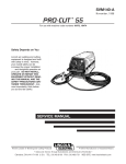
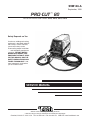
PRO-CUT 80
For use with machine code numbers 10573, 10574, 10577, 10578
Safety Depends on You
Lincoln arc welding and cutting
equipment is designed and built
with safety in mind. However,
your overall safety can be
increased by proper installation
. . . and thoughtful operation on
your part. DO NOT INSTALL,
OPERATE OR REPAIR THIS
EQUIPMENT WITHOUT READING THIS MANUAL AND THE
SAFETY PRECAUTIONS CONTAINED THROUGHOUT. And,
most importantly, think before
you act and be careful.
SERVICE MANUAL
• World's Leader in Welding and Cutting Products •
• Sales and Service through Subsidiaries and Distributors Worldwide •
Cleveland, Ohio 44117-1199 U.S.A. TEL: 216.481.8100 FAX: 216.486.1751 WEB SITE: www.lincolnelectric.com
i
i
SAFETY
WARNING
CALIFORNIA PROPOSITION 65 WARNINGS
Diesel engine exhaust and some of its constituents
are known to the State of California to cause cancer, birth defects, and other reproductive harm.
The Above For Diesel Engines
The engine exhaust from this product contains
chemicals known to the State of California to cause
cancer, birth defects, or other reproductive harm.
The Above For Gasoline Engines
ARC WELDING CAN BE HAZARDOUS. PROTECT YOURSELF AND OTHERS FROM POSSIBLE SERIOUS INJURY OR DEATH.
KEEP CHILDREN AWAY. PACEMAKER WEARERS SHOULD CONSULT WITH THEIR DOCTOR BEFORE OPERATING.
Read and understand the following safety highlights. For additional safety information, it is strongly recommended that you purchase a copy of “Safety in Welding & Cutting - ANSI Standard Z49.1” from the American Welding Society, P.O. Box 351040,
Miami, Florida 33135 or CSA Standard W117.2-1974. A Free copy of “Arc Welding Safety” booklet E205 is available from the
Lincoln Electric Company, 22801 St. Clair Avenue, Cleveland, Ohio 44117-1199.
BE SURE THAT ALL INSTALLATION, OPERATION, MAINTENANCE AND REPAIR PROCEDURES ARE
PERFORMED ONLY BY QUALIFIED INDIVIDUALS.
FOR ENGINE
powered equipment.
1.h. To avoid scalding, do not remove the
radiator pressure cap when the engine is
hot.
1.a. Turn the engine off before troubleshooting and maintenance
work unless the maintenance work requires it to be running.
____________________________________________________
1.b. Operate engines in open, well-ventilated
areas or vent the engine exhaust fumes
outdoors.
____________________________________________________
1.c. Do not add the fuel near an open flame welding arc or when the engine is running. Stop
the engine and allow it to cool before refueling to prevent spilled fuel from vaporizing on
contact with hot engine parts and igniting. Do
not spill fuel when filling tank. If fuel is spilled,
wipe it up and do not start engine until fumes
have been eliminated.
____________________________________________________
1.d. Keep all equipment safety guards, covers and
devices in position and in good repair.Keep
hands, hair, clothing and tools away from Vbelts, gears, fans and all other moving parts
when starting, operating or repairing equipment.
____________________________________________________
ELECTRIC AND
MAGNETIC FIELDS
may be dangerous
2.a. Electric current flowing through any conductor causes
localized Electric and Magnetic Fields (EMF). Welding
current creates EMF fields around welding cables and
welding machines
2.b. EMF fields may interfere with some pacemakers, and
welders having a pacemaker should consult their physician
before welding.
2.c. Exposure to EMF fields in welding may have other health
effects which are now not known.
2.d. All welders should use the following procedures in order to
minimize exposure to EMF fields from the welding circuit:
1.e. In some cases it may be necessary to remove safety
guards to perform required maintenance. Remove
guards only when necessary and replace them when the
maintenance requiring their removal is complete.
Always use the greatest care when working near moving
parts.
___________________________________________________
1.f. Do not put your hands near the engine fan. Do not attempt to
override the governor or idler by pushing on the throttle control rods while the engine is running.
___________________________________________________
1.g. To prevent accidentally starting gasoline engines while
turning the engine or welding generator during maintenance
work, disconnect the spark plug wires, distributor cap or
magneto wire as appropriate.
PRO-CUT 80
2.d.1. Route the electrode and work cables together - Secure
them with tape when possible.
2.d.2. Never coil the electrode lead around your body.
2.d.3. Do not place your body between the electrode and
work cables. If the electrode cable is on your right
side, the work cable should also be on your right side.
2.d.4. Connect the work cable to the workpiece as close as
possible to the area being welded.
2.d.5. Do not work next to welding power source.
ii
ii
SAFETY
ELECTRIC SHOCK can kill.
ARC RAYS can burn.
3.a. The electrode and work (or ground) circuits
are electrically “hot” when the welder is on.
Do not touch these “hot” parts with your bare
skin or wet clothing. Wear dry, hole-free
gloves to insulate hands.
4.a. Use a shield with the proper filter and cover
plates to protect your eyes from sparks and
the rays of the arc when welding or observing
open arc welding. Headshield and filter lens
should conform to ANSI Z87. I standards.
3.b. Insulate yourself from work and ground using dry insulation.
Make certain the insulation is large enough to cover your full
area of physical contact with work and ground.
4.b. Use suitable clothing made from durable flame-resistant
material to protect your skin and that of your helpers from
the arc rays.
In addition to the normal safety precautions, if welding
must be performed under electrically hazardous
conditions (in damp locations or while wearing wet
clothing; on metal structures such as floors, gratings or
scaffolds; when in cramped positions such as sitting,
kneeling or lying, if there is a high risk of unavoidable or
accidental contact with the workpiece or ground) use
the following equipment:
• Semiautomatic DC Constant Voltage (Wire) Welder.
• DC Manual (Stick) Welder.
• AC Welder with Reduced Voltage Control.
4.c. Protect other nearby personnel with suitable, non-flammable
screening and/or warn them not to watch the arc nor expose
themselves to the arc rays or to hot spatter or metal.
FUMES AND GASES
can be dangerous.
5.a. Welding may produce fumes and gases
hazardous to health. Avoid breathing these
fumes and gases.When welding, keep
your head out of the fume. Use enough
ventilation and/or exhaust at the arc to keep
fumes and gases away from the breathing zone. When
welding with electrodes which require special
ventilation such as stainless or hard facing (see
instructions on container or MSDS) or on lead or
cadmium plated steel and other metals or coatings
which produce highly toxic fumes, keep exposure as
low as possible and below Threshold Limit Values (TLV)
using local exhaust or mechanical ventilation. In
confined spaces or in some circumstances, outdoors, a
respirator may be required. Additional precautions are
also required when welding on galvanized steel.
3.c. In semiautomatic or automatic wire welding, the electrode,
electrode reel, welding head, nozzle or semiautomatic
welding gun are also electrically “hot”.
3.d. Always be sure the work cable makes a good electrical
connection with the metal being welded. The connection
should be as close as possible to the area being welded.
3.e. Ground the work or metal to be welded to a good electrical
(earth) ground.
3.f. Maintain the electrode holder, work clamp, welding cable and
welding machine in good, safe operating condition. Replace
damaged insulation.
3.g. Never dip the electrode in water for cooling.
3.h. Never simultaneously touch electrically “hot” parts of
electrode holders connected to two welders because voltage
between the two can be the total of the open circuit voltage
of both welders.
3.i. When working above floor level, use a safety belt to protect
yourself from a fall should you get a shock.
3.j. Also see Items 6.c. and 8.
5.b. Do not weld in locations near chlorinated hydrocarbon vapors
coming from degreasing, cleaning or spraying operations.
The heat and rays of the arc can react with solvent vapors to
form phosgene, a highly toxic gas, and other irritating
products.
5.c. Shielding gases used for arc welding can displace air and
cause injury or death. Always use enough ventilation,
especially in confined areas, to insure breathing air is safe.
5.d. Read and understand the manufacturer’s instructions for this
equipment and the consumables to be used, including the
material safety data sheet (MSDS) and follow your
employer’s safety practices. MSDS forms are available from
your welding distributor or from the manufacturer.
5.e. Also see item 1.b.
PRO-CUT 80
iii
iii
SAFETY
WELDING SPARKS can
cause fire or explosion.
CYLINDER may explode
if damaged.
6.a. Remove fire hazards from the welding area.
If this is not possible, cover them to prevent
the welding sparks from starting a fire.
Remember that welding sparks and hot
materials from welding can easily go through small cracks
and openings to adjacent areas. Avoid welding near
hydraulic lines. Have a fire extinguisher readily available.
6.b. Where compressed gases are to be used at the job site,
special precautions should be used to prevent hazardous
situations. Refer to “Safety in Welding and Cutting” (ANSI
Standard Z49.1) and the operating information for the
equipment being used.
7.a. Use only compressed gas cylinders
containing the correct shielding gas for the
process used and properly operating
regulators designed for the gas and
pressure used. All hoses, fittings, etc. should be suitable for
the application and maintained in good condition.
7.b. Always keep cylinders in an upright position securely
chained to an undercarriage or fixed support.
7.c. Cylinders should be located:
• Away from areas where they may be struck or subjected to
physical damage.
6.c. When not welding, make certain no part of the electrode
circuit is touching the work or ground. Accidental contact can
cause overheating and create a fire hazard.
6.d. Do not heat, cut or weld tanks, drums or containers until the
proper steps have been taken to insure that such procedures
will not cause flammable or toxic vapors from substances
inside. They can cause an explosion even though they have
been “cleaned”. For information, purchase “Recommended
Safe Practices for the Preparation for Welding and Cutting of
Containers and Piping That Have Held Hazardous
Substances”, AWS F4.1 from the American Welding Society
(see address above).
6.e. Vent hollow castings or containers before heating, cutting or
welding. They may explode.
6.f. Sparks and spatter are thrown from the welding arc. Wear oil
free protective garments such as leather gloves, heavy shirt,
cuffless trousers, high shoes and a cap over your hair. Wear
ear plugs when welding out of position or in confined places.
Always wear safety glasses with side shields when in a
welding area.
6.g. Connect the work cable to the work as close to the welding
area as practical. Work cables connected to the building
framework or other locations away from the welding area
increase the possibility of the welding current passing
through lifting chains, crane cables or other alternate circuits.
This can create fire hazards or overheat lifting chains or
cables until they fail.
6.h. Also see item 1.c.
• A safe distance from arc welding or cutting operations and
any other source of heat, sparks, or flame.
7.d. Never allow the electrode, electrode holder or any other
electrically “hot” parts to touch a cylinder.
7.e. Keep your head and face away from the cylinder valve outlet
when opening the cylinder valve.
7.f. Valve protection caps should always be in place and hand
tight except when the cylinder is in use or connected for
use.
7.g. Read and follow the instructions on compressed gas
cylinders, associated equipment, and CGA publication P-l,
“Precautions for Safe Handling of Compressed Gases in
Cylinders,” available from the Compressed Gas Association
1235 Jefferson Davis Highway, Arlington, VA 22202.
FOR ELECTRICALLY
powered equipment.
8.a. Turn off input power using the disconnect
switch at the fuse box before working on
the equipment.
8.b. Install equipment in accordance with the U.S. National
Electrical Code, all local codes and the manufacturer’s
recommendations.
8.c. Ground the equipment in accordance with the U.S. National
Electrical Code and the manufacturer’s recommendations.
PRO-CUT 80
iv
SAFETY
PRÉCAUTIONS DE SÛRETÉ
Pour votre propre protection lire et observer toutes les instructions
et les précautions de sûreté specifiques qui parraissent dans ce
manuel aussi bien que les précautions de sûreté générales suivantes:
Sûreté Pour Soudage A L’Arc
1.
iv
Protegez-vous contre la secousse électrique:
a.
b.
Les circuits à l’électrode et à la piéce sont sous tension
quand la machine à souder est en marche. Eviter toujours tout contact entre les parties sous tension et la
peau nue ou les vétements mouillés. Porter des gants
secs et sans trous pour isoler les mains.
Faire trés attention de bien s’isoler de la masse quand
on soude dans des endroits humides, ou sur un plancher metallique ou des grilles metalliques, principalement
dans les positions assis ou couché pour lesquelles une
grande partie du corps peut être en contact avec la
masse.
c.
Maintenir le porte-électrode, la pince de masse, le câble
de soudage et la machine à souder en bon et sûr état
defonctionnement.
d.
Ne jamais plonger le porte-électrode dans l’eau pour le
refroidir.
e.
Ne jamais toucher simultanément les parties sous tension des porte-électrodes connectés à deux machines à
souder parce que la tension entre les deux pinces peut
être le total de la tension à vide des deux machines.
2.
Dans le cas de travail au dessus du niveau du sol, se protéger
contre les chutes dans le cas ou on recoit un choc. Ne jamais
enroule le câble-électrode autour de n’importe quelle partie
du corps.
3.
Un coup d’arc peut être plus sévère qu’un coup de soliel,
donc:
a.
Utiliser un bon masque avec un verre filtrant approprié
ainsi qu’un verre blanc afin de se protéger les yeux du
rayonnement de l’arc et des projections quand on soude
ou quand on regarde l’arc.
b.
Porter des vêtements convenables afin de protéger la
peau de soudeur et des aides contre le rayonnementde
l’arc.
c.
Protéger l’autre personnel travaillant à proximité au
soudage à l’aide d’écrans appropriés et non-inflammables.
4.
Des gouttes de laiter en fusion sont émises de l’arc de
soudage. Se protéger avec es vêtements de protection libres
de l’huile, tels que les gants en cuir, chemise épaisse, pantalons sans revers, et chaussures montantes.
5.
Toujours porter des lunettes de sécurité dans la zone de
soudage. Utiliser des lunettes avec écrans lateraux dans les
zones où l’on pique le laitier.
6.
Eloigner les matériaux inflammables ou les recouvrir afin de
prévenir ttout risque d’incendie dû étincelles.
7. Quand on ne soude pas, poser la pince à une endroit isolé
de la masse. Un court-circuit accidental peut provoquer un
échauffement et un risque d’incendie.
8. S’assurer que la masse est connectée le plus prés possible
de la zone de travail qu’il est pratique de la faire. Si on place
la masse sur la charpente de la construction ou d’autres
endroits éloignés de la zone de travail, on augmente le
risque de voir passer le courant de soudage par les chaines
de levage, câbles de grue, ou atres circuits. Cela peut
provoquer des risques d’incendie ou d’echauffement des
chaines et des câbles jusqu’à ce qu’ils se rompent.
9. Assurer une ventilation suffisante dans la zone de soudage.
Ceci est particuliérement important pour le soudage de tôles
galvanisées plombées, ou cadmiées ou tout autre métal qui
produit des fumées toxiques.
10. Ne pas souder en présence de vapeurs de chlore provenant
d’opéerations de dégraissage, nettoyage ou pistolage. La
chaleur ou les rayons de l’arc peuvent réagir avec les
vapeurs du solvant pour produire du phosgéne (gas fortement roxique) ou autres produits irritants.
PRÉCAUTIONS DE SÛRETÉ POUR LES
MACHINES À SOUDER À TRANSFORMATEUR ET À REDRESSEUR
1.
Relier à la terre le chassis du poste conformement au code
de l’électricité et aux recommendations du fabricant. Le dispositif de montage ou la piece à souder doit être branché à
une bonne mise à la terre.
2.
Autant que possible, l’installation et l’entretien du poste
seront effectués par un électricien qualifié.
3.
Avant de faires des travaux à l’interieur de poste, la
debrancher à l’interrupteur à la boite de fusibles.
4.
Garder tous les couvercles et dispostifis de sûreté à leur
place.
PRO-CUT 80
v
v
MASTER TABLE OF CONTENTS FOR ALL SECTIONS
Page
Safety.................................................................................................................................................i-iv
Installation .............................................................................................................................Section A
Technical Specifications ..........................................................................................................A-2/3
Safety Precautions......................................................................................................................A-4
Select Suitable Location .............................................................................................................A-4
Stacking ......................................................................................................................................A-4
Lifting and Moving ......................................................................................................................A-4
Tilting...........................................................................................................................................A-4
High Frequency Interference Protection.....................................................................................A-4
Input Electrical Connections.......................................................................................................A-5
Input Power Cord Connector Installation ...................................................................................A-5
Frame Grounding ........................................................................................................................A-5
Gas Input Connections ...............................................................................................................A-7
Output Connections....................................................................................................................A-8
Operation...............................................................................................................................Section B
Safety Precautions......................................................................................................................B-2
General Description ....................................................................................................................B-3
Recommended Processes and Equipment................................................................................B-3
Operational Features and Controls ............................................................................................B-3
Design Features and Advantages ..............................................................................................B-3
Cutting Capability .......................................................................................................................B-4
Consumable Life.........................................................................................................................B-4
Limitations ..................................................................................................................................B-4
Controls and Settings.................................................................................................................B-5
Pilot Arc Discussion....................................................................................................................B-5
Cutting Operation .......................................................................................................................B-5
User Responsibility.....................................................................................................................B-7
Preheat Temperature for Plasma Cutting ...................................................................................B-7
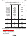
Procedure Recommendations ....................................................................................................B-7
Accessories...........................................................................................................................Section C
Maintenance .........................................................................................................................Section D
Theory of Operation .............................................................................................................Section E
Troubleshooting and Repair.................................................................................................Section F
Safety Precautions ......................................................................................................................F-2
How to Use Troubleshooting Guide............................................................................................F-2
Troubleshooting Guide ................................................................................................................F-4
Test Procedures ........................................................................................................................F-10
Replacement Procedures .........................................................................................................F-40
Electrical Diagrams ..............................................................................................................Section G
Parts Manual ....................................................................................................................P-340 Series
PRO-CUT 80
Section A-1
TABLE OF CONTENTS
- INSTALLATION SECTION -
Section A-1
Installation
Technical Specifications .............................................................................................................A-2
Safety Precautions......................................................................................................................A-4
Select Suitable Location.............................................................................................................A-4
Stacking ......................................................................................................................................A-4
Lifting and Moving ......................................................................................................................A-4
Tilting ..........................................................................................................................................A-4
High Frequency Interference Protection.....................................................................................A-4
Input Electrical Connections.......................................................................................................A-5
Ground Connection ..............................................................................................................A-5
Input Power Cord Connector Installation ...................................................................................A-5
Input Wire and Fuse Size .....................................................................................................A-5
Reconnect Procedure...........................................................................................................A-6
Gas Input Connections...............................................................................................................A-7
Output Connections ...................................................................................................................A-8
Torch Connection .................................................................................................................A-8
PRO-CUT 80
A-2
A-2
INSTALLATION
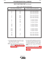
TECHNICAL SPECIFICATIONS - PRO-CUT 80
INPUT RATINGS
Single Phase Input
Voltage and Hertz
Input Currents
Rated Output Amps
208/1/60
230/1/60
460/1/60
87
81
48
80
80
80
Three Phase Input
Voltage and Hertz
Input Currents
Rated Output Amps
208/3/60
230/3/60
460/3/60
48
44
25
80
80
80
IDLE CURRENT AND WATTS
IDLE CURRENT AND WATTS
230/1/60
0.61 Amps
140 Watts
RATED OUTPUT
Duty Cycle
Rated Output Amps
60%
100%
80
60
OUTPUT
Current Range
Open Circuit Voltage
Pilot Current
35 - 85 Amps
335VDC Maximum
20 Amps @ 100%
Duty Cycle
PRO-CUT 80
A-3
A-3
INSTALLATION
TECHNICAL SPECIFICATIONS (Cont’d) - PRO-CUT 80
GAS REQUIREMENTS
Required Gas Flow Rate
Required Gas Inlet Pressure
70 PSI @ 480 SCHF
(4.8 Bar. @ 13550 LHR)
80 to 150 PSI
(5.4 Bar. to 10.2 Bar.)
RECOMMENDED INPUT WIRE AND FUSE SIZES
For all plasma cutting applications based on U.S. National Electrical Code
Ambient Temperature 30°C or Less
AC Input Voltage
at
60 Hertz
Fuse (Super Lag)
Circuit Breaker
(Delay Type)
Type 75°C
Copper Wire in Conduit AWG
(IEC) Sizes
230VAC Single Phase
460VAC Single Phase
100 Amps
60 Amps
#4 (21.1mm2)
#8 (8.4mm2)
#4 (21.1mm2)
#8 (8.4mm2)
230VAC Three Phase
460VAC Three Phase
60 Amps
40 Amps
#8 (8.4mm2)
#10 (5.3mm2)
#8 (8.4mm2)
#10 (5.3mm2)
PHYSICAL DIMENSIONS
Height
Width
Depth
Weight with
Torch Cable
16.5 Inches
419 mm
13.75 Inches
349 mm
29.5 Inches
749 mm
98 lbs. (44.5 kg.)
(25 ft. cable)
113 lbs. (51.4 kg.)
(50 ft. cable)
PRO-CUT 80
A-4
A-4
INSTALLATION
Read this entire installation section before you
start installation.
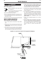
LIFTING AND MOVING
WARNING
SAFETY PRECAUTIONS
FALLING EQUIPMENT can cause
injury.
WARNING
¥ Do not use the pull handle on the
optional undercarriage, if installed,
to lift the machine. This handle is
not designed to support the full
weight of the machine. Using it to
lift the machine could cause personal injury or damage to the
machine.
ELECTRIC SHOCK can kill.
¥ Turn the input power OFF at the
disconnect switch or fuse box
and discharge input capacitors
before working inside the equipment.
¥ Do not touch electrically hot parts or electrodes with
your skin or wet clothing.
¥ Always connect the 80 grounding terminal (located
on the side of the Case Back Assembly) to a good
electrical earth ground.
¥ Always wear dry, insulating gloves.
¥ Turn the 80 Power Switch OFF when connecting
power cord to input power.
Only qualified personnel should install, use, or service this equipment.
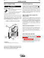
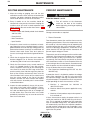
SELECT SUITABLE LOCATION
Place the PRO-CUT 80 where clean cool air can freely
circulate in through the rear louvers and out through
the front/bottom opening. Dirt, dust or any foreign
material that can be drawn into the machine should be
kept at a minimum. Failure to observe these precautions can result in excessive operating temperatures
and nuisance shutdown of the machine.
A source of clean, dry air or nitrogen must be supplied
to the PRO-CUT 80. Oil in the air is a severe problem
and must be avoided. The supply pressure must be
between 80 and 150 psi. The flow rate is approximately 6.0 cfm (170 l/min.). Failure to observe these precautions could result in excessive operating temperatures or damage to the torch.
STACKING
The PRO-CUT 80 cannot be stacked.
¥ Either the front or rear handles or both may be used
to lift or move the machine.
TILTING
The PRO-CUT 80 must be placed on a stable, level
surface so it will not topple over.
HIGH FREQUENCY INTERFERENCE
PROTECTION
The PRO-CUT 80 employs a touch start mechanism
for arc initiation. This eliminates high frequency emissions from the machine as compared with spark gap
and solid state type high frequency generators. Keep
in mind, though, that these machines may be used in
an environment where other high frequency generating
machines are operating. By taking the following steps,
you can minimize high frequency interference.
¥ Make sure the power supply chassis is connected to
a good earth ground. The work terminal ground does
NOT ground the machine frame.
¥ Keep the work ground clamp isolated from other work
clamps that have high frequency.
¥ If the ground clamp cannot be isolated, then keep the
clamp as far as possible from other work clamp connections.
¥ When the machine is enclosed in a metal building,
several good earth driven electrical grounds around
the periphery of the building are recommended.
Failure to observe these recommended installation procedures may cause improper function of the Pro-Cut or
possibly even damage the control system or power
supply components.
PRO-CUT 80
A-5
INSTALLATION
INPUT CONNECTIONS
A-5
GROUND CONNECTION
WARNING
ELECTRIC SHOCK can kill.
¥ Have a qualified electrician install and
service this equipment.
¥ Turn the input power off at the fuse box
before working on this equipment.
The frame of the PRO-CUT 80 must be properly grounded.
A ground terminal marked with the symbol
is
mounted on the case bottom directly behind the input
power switch for this purpose. The ground lead of the
input power cord that is attached to the machine must
be connected to this ground terminal. See the
National Electric Code for details on proper grounding
methods. Install in accordance with all local and
national electrical codes.
¥ Do not touch electrically hot parts.
Before installing the machine, check that input supply
voltage, phase, and frequency are the same as the
machineÕ
s voltage, phase, and frequency as specified
on the machineÕ
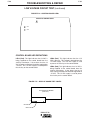
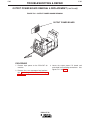
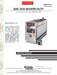
s rating plate. See Figure A.1.
FIGURE A.1 Ð RATING PLATE LOCATION
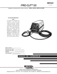
INPUT POWER CORD CONNECTOR
INSTALLATION
The PRO-CUT 80 is supplied with one 11 foot (3.35m)
#8 AWG 3 lead input power cord already connected to
the machine. A cord connector provides a strain relief
for the input power cord as it passes through the left
rear access hole. The cord connector is designed for
a cord diameter of .40 - 1.03 in (10.2 - 26.2mm) if it
becomes necessary to install a different input cord.
See Figure A.1.
For three phase connection: Replace the input power
cord with a #10 AWG 4 lead cable.
1
Connect the leads of the cable to a fused power panel.
Make sure the green lead is connected to the panel
and the panel is connected to a good earth ground.
Install in accordance with all local and national electric
codes.
INPUT WIRE AND FUSE SIZE
Fuse the input circuit with the super lag fuses or delay
type circuit breakers recommended on the Technical
Specifications page. Choose an input and grounding
wire size according to local or national codes; also see
the Technical Specifications page. Using fuses or
circuit breakers smaller than recommended may result
in ÒnuisanceÓ shut-of
fs from inrush currents, even if
you are not cutting at high currents.
2
3
1. CASE BACK
2. RATING PLATE
3. POWER CORD CONNECTOR WITH STRAIN RELIEF
The PRO-CUT 80 should be connected only by a qualified electrician. Installation should be made in accordance with the U.S. National Electrical Code, all local
codes, and the information detailed below.
PRO-CUT 80
A-6
A-6
INSTALLATION
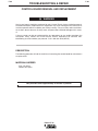
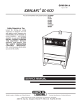
RECONNECT PROCEDURE
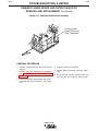
FIGURE A.2 Ð RECONNECTION DIAGRAM
When received directly from the factory, the machines
are internally connected for 230 VAC. Reconnection
will be necessary if a higher input voltage is used. To
reconnect the Pro-Cut to 460 VAC or to connect back
to 230 VAC, follow the directions as outlined below.
Follow this procedure ONLY while the Pro-Cut is disconnected from the input power.
RECONNECT PROCEDURE
WARNING
¥ Disconnect input power before
inspecting or servicing machine.
¥ Do not operate with wraparound
removed.
CAUTION
Failure to follow these instructions can cause immediate failure of components in the welder.
ELECTRIC
SHOCK
CAN KILL
¥ Do not touch electrically live parts.
¥ Only qualified persons should install,
use, or service this equipment.
1. BE SURE POWER SWITCH IS OFF.
2. CONNECT LEAD 'A' TO DESIRED INPUT VOLTAGE RANGE.
440 - 460V
1. Open the access door on the side of the machine.
Connection instructions are also included on the
inside of the door.
2. For 230: Position the large switch to 200-230. See
Figure A.2.
380 - 415V
220 - 230V
'A'
200 - 208V
3. POSITION SWITCH TO DESIRED INPUT VOLTAGE RANGE.
For 460: Position the large switch to 380-460. See
Figure A-2.
VOLTAGE = 380 - 460V
3. Move the ÒAÓ lead to the appr
opriate terminal.
VOLTAGE = 200 - 230V
PRO-CUT 80
A-7
A-7
INSTALLATION
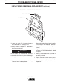
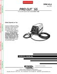
GAS INPUT CONNECTIONS
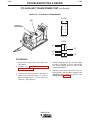
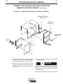
FIGURE A.3 - COMPRESSED GAS CONNECTION
Supply the PRO-CUT 80 with clean compressed air or
nitrogen.
• Supply pressure must be between 80 psi and 150
psi.
1
• Flow rate should be approximately 6.0 cfm (170
I/min.).
NOTE: Oil in the air supply to the PRO-CUT 80 can
cause severe problems. Use only a clean air
supply.
2
• Connect the gas supply to the PRO-CUT 80’s
pneumatic nipple at the air filter. See Figure A.3.
3
• Compressed gas should be supplied to the fitting
connection mounted on the filter at the rear of the
machine. If necessary, this fitting can be removed
allowing plumbing access through the 1/4 in.
(6.4mm) NPT input port on the filter body.
4
WARNING
CYLINDER could explode if damaged.
• Keep cylinder upright and chained to a fixed support.
• Keep cylinder away from areas
where it could be damaged.
• Never lift machine with cylinder
attached.
1.
2.
3.
4.
CASE BACK
PNEUMATIC NIPPLE
AIR FILTER
FLEX TUBE (TO REGULATOR INSIDE MACHINE)
• Never allow the cutting torch to
touch the cylinder.
• Keep cylinder away from live electrical parts.
• Maximum inlet pressure 150 psi.
NOTE: When using nitrogen gas from a cylinder, the
cylinder must have a pressure regulator.
• Maximum psi from nitrogen gas cylinder to PROCUT 80 regulator should never exceed 150 psi.
• Install a hose between the nitrogen gas cylinder
regulator and the PRO-CUT 80 gas inlet.
PRO-CUT 80
A-8
A-8
INSTALLATION
OUTPUT CONNECTIONS
FIGURE A.4 - TORCH CONNECTION
AT CASE FRONT
TORCH CONNECTION
Status
Indicators
The PRO-CUT 80 is supplied from the factory with a
PCT 80 cutting torch. Additional cutting torches can
be ordered from the K1571 series. Hand-held and
mechanized torches come with 25 or 50 foot cables.
All torches are connected to the Pro-Cut with a quick
connect at the case front for easy change over. See
Figure A-4.
For more information on the torch and its components,
refer to the PCT 80 OperatorÕ
s Manual (IM595).
Reset
Button
XXXX
XXXX
XXXX
Gas
Purge
Button
Gas
Regulator
Gauge
XXXX
Gas
Regulator
Knob
Output
Control
Knob
P R O-C UT 80
Consumable
Storage
(behind
door)
Torch
Connector
PRO-CUT 80
Input
Power
Switch
Work
Cable
Interface
Connector
Section B-1
Section B-1
TABLE OF CONTENTS
- OPERATION SECTION Operation...............................................................................................................................Section B
Safety Instructions ......................................................................................................................B-2
General Description ....................................................................................................................B-3
Recommended Process and Equipment....................................................................................B-3
Operational Features and Controls ............................................................................................B-3
Design Features and Advantages...............................................................................................B-3
Cutting Capability .......................................................................................................................B-4
Consumable Life.........................................................................................................................B-4
Limitations...................................................................................................................................B-4
Controls and Settings .................................................................................................................B-5
Pilot Arc Considerations .............................................................................................................B-5
Cutting Operation .......................................................................................................................B-5
Safety Status Indicator .............................................................................................................. B-6
User Responsibility .....................................................................................................................B-7
Preheat Temperature for Plasma Cutting ...................................................................................B-7
Procedure Recommendations ....................................................................................................B-7
General .................................................................................................................................B-7
Thin Gauge Sheet Metal ......................................................................................................B-7
Thick Sections of Metal........................................................................................................B-8
Suggestions for Extra Utility From the Pro-Cut System ......................................................B-8
Machine Interface........................................................................................................................B-9
Arc Start.......................................................................................................................................B-9
Arc Initiated.................................................................................................................................B-9
Arc Voltage..................................................................................................................................B-9
PRO-CUT 80
B-2
OPERATION
OPERATING INSTRUCTIONS
Read and understand this entire section of operating
instructions before operating the machine.
SAFETY INSTRUCTIONS
WARNING
ELECTRIC SHOCK can kill.
• Do not touch electrically live parts or
electrodes with your skin or wet clothing.
• Insulate yourself from the work and ground.
• Always wear dry, insulating gloves.
FUMES AND GASES can be
dangerous.
• Keep your head out of fumes.
• Use ventilation or exhaust to remove fumes from
breathing zone.
CUTTING SPARKS can cause
fire or explosion.
• Keep flammable material away.
• Do not cut containers that have held combustibles.
ARC RAYS can burn.
• Wear eye, ear, and body protection.
PLASMA ARC can injure.
• Keep your body away from nozzle and
plasma arc.
• Operate the pilot arc with caution. The
pilot arc is capable of burning the operator, others, or even piercing safety
clothing.
Observe additional Safety Guidelines detailed in
the beginning of this manual.
PRO-CUT 80
B-2
B-3
OPERATION
GENERAL DESCRIPTION
The PRO-CUT 80 is an inverter based constant current, continuous control plasma cutting power source.
It provides superior and reliable starting characteristics, cutting visibility and arc stability. When cutting
expanded metal, the PRO-CUT 80 out-performs the
competition due to its quick, clean response to arc
transfers. The power supply design provides high
transfer-to-cut distances, which makes pierce cutting
more reliable with less nozzle wear. The control system
has a safety mechanism to insure that the nozzle and
electrode are in place before cutting or gouging. This
is extremely important due to the high voltages
involved.
The PRO-CUT 80 comes standard with an air regulator, coarse air filter, and pressure gauge. There are six
different torch and cable systems to choose from:
hand-held torch with 25Õ or 50Õ cable, machine and
robotic torch both with 25Õ and 50Õ cable.
Consumables are included so that cutting can begin
right out of the box. Consumables can also be
ordered as individual packages.
The PRO-CUT 80 initiates the plasma arc with a simple, yet reliable, touch-start mechanism. This system
eliminates many of the failure problems associated
with hi-frequency start systems. The PRO-CUT 80 is
capable of cutting with nitrogen or air.
The PRO-CUT 80 is controlled by a microprocessorbased control board. The machine performs rudimentary self troubleshooting when powered up, which aids
in field servicing.
RECOMMENDED PROCESSES AND
EQUIPMENT
The PRO-CUT 80 is capable of all cutting and gouging
applications within its output capacity of 35 to 85
amps. These applications include thin gage sheet
metal and expanded metal.
B-3
DESIGN FEATURES AND
ADVANTAGES
The microprocessor controlled PRO-CUT 80 design
makes plasma cutting and gouging tasks uncomplicated. This list of design features and advantages will
help you understand the machine's total capabilities
so that you can get maximum use from your machine.
¥ Light weight and portable design for industrial use.
¥ Continuous control, 35 - 85 amps.
¥ Reliable touch start mechanism for plasma arc initiation.
¥ Unique microprocessor controlled starting
sequence for safe and consistent starting.
¥ Rapid arc transfer for fast cutting of expanded
metal.
¥ High transfer distance for ease of use.
¥ Input overvoltage protection.
¥ 3.0 second pilot arc.
¥ Purge momentary push button.
¥ Air regulator and pressure gauge located on the
front of machine for convenience.
¥ ÓParts-in-PlaceÓ mechanism to detect pr
oper installation of consumables and torch.
¥ Automatic detection of faulty output control.
¥ In-line coarse air filter.
¥ Preflow/Postflow timing. Preflow is eliminated if arc
is re-initiated in Postflow.
¥ Thermostatic Protection.
¥ Solid state overcurrent protection.
¥ Works with pure nitrogen for cutting nonferrous
materials.
¥ Reconnectable for multiple input voltages.
¥ Quick disconnect torch.
OPERATIONAL FEATURES AND
CONTROLS
¥ Display indicators for machine status.
The PRO-CUT 80 comes with an ON/OFF POWER
SWITCH, OUTPUT CURRENT CONTROL, PURGE
BUTTON, STATUS INDICATORS and a SAFETY
RESET BUTTON. See Figure B.2 and related discussion.
¥ Swirl texture inside Vortechª nozzle for better start ing reliability and higher quality cuts.
¥ Unique electrode and Vortechª nozzle design for
optimum cooling and long life.
¥ Unique drag cup design for durability and elimination of double arcing.
PRO-CUT 80
B-4
B-4
OPERATION
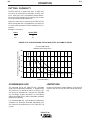
CUTTING CAPABILITY
The PRO-CUT 80 is rated at 80 amps, at 60% duty
cycle on a 10 minute basis or 60 amps, at 100% duty
cycle. If the duty cycle is exceeded, a thermal protector will shut off the output of the machine until it cools
to the normal operating temperature.
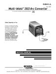
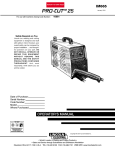
Figure B.1 shows the cut capacity of the PRO-CUT 80
when cutting mild steel. The graph plots cut thickness
vs. torch travel speed with a torch standoff of 0.15 in.
(3.8mm).
Example: 0.5 material
Amps
Speed (IPM)
55
80
25
35
FIGURE B.1 Ð LINCOLNÕS PRO-CUT 80 MILD STEEL CUT CAP
ACITY CHART
Lincoln's PRO-CUT 80
Mild Steel Cut Capacity Chart
Recommended Torch Travel Speed (IPM)
80% of Maximum Speed
100
80
60
40
20
25 A
0
0.000
0.125
55 A
35 A
0.250
0.375
0.500
Material Thickness
0.625
0.750
80 A
1.00
CONSUMABLE LIFE
LIMITATIONS
The expected life for the PRO-CUT 80's electrode
under normal operating conditions is approximately
160 starts/cuts. An erosion of .060 in. (1.5mm) is typical for end of electrode life. However, the electrode
may last longer. A green and erratic arc will indicate
definite electrode failure, and the electrode should be
replaced immediately.
Do not exceed output current and duty cycle rating of
machine. Do not use the PRO-CUT 80 for pipe thawing.
It is recommended that consumables be replaced in
complete sets. (Example: Electrode and Nozzle). This
will maximize the performance of the PRO-CUT 80
system.
PRO-CUT 80
B-5
OPERATION
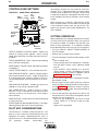
CONTROLS AND SETTINGS
FIGURE B.2 - CASE FRONT CONTROLS
Status
Indicators
Reset
Button
XXXX
XXXX
XXXX
Gas
Purge
Button
Gas
Regulator
Gauge
XXXX
Gas
Regulator
Knob
Output
Control
Knob
Occasionally, the pilot arc may sputter or start intermittently. This is aggravated when the consumables
are worn or the air pressure is too high. Always keep
in mind that the pilot arc is designed to transfer the arc
to the workpiece and not for numerous starts without
cutting.
When the pilot arc is started, a slight impulse will be
felt in the torch handle. This occurrence is normal and
is the mechanism which starts the plasma arc. This
impulse can also be used to help troubleshoot a "no
start" condition.
PRO-CUT 80
Consumable
Storage
(behind
door)
Torch
Connector
B-5
CUTTING OPERATION
Input
Power
Switch
Work
Cable
Interface
Connector
OUTPUT CURRENT CONTROL KNOB - Adjusts the
amount of cutting current applied. Affects cutting
speed, dross formation, cut width, heat zone and travel speed.
TORCH CONNECTOR - Quick- connect type coupling
for the PCT 80 cutting torch.
WORK CABLE - Provides clamp and cable connection
to workpiece.
ON/OFF POWER SWITCH - Turns machine on or off.
GAS REGULATOR KNOB - Adjusts compressed gas
pressure delivered to the torch. Length of torch hose
is an adjustment factor. Optimum setting is 70-75 psi.
The gas purge button must be pressed in to set pressure.
GAS REGULATOR GUAGE - Provides gas presssure
reading as set by the gas regulator knob.
GAS PURGE BUTTON - Used to check or set gas
pressure. Push in and hold to check pressure, then
continue to hold to set the pressure. Shuts off gas
when released.
RESET BUTTON - Used to reset the machine following
a safety circuit trip.
STATUS (DISPLAY) BOARD INDICATORS - Four lights
indicating Power, Gas Low, Thermal and Safety.
When preparing to cut or gouge, position the machine
as close to the work as possible. Make sure you have
all materials needed to complete the job and have
taken all safety precautions. It is important to follow
these operating steps each time you use the machine.
• Turn the machine's ON/OFF POWER SWITCH to
the OFF position.
• Connect the air supply to the machine.
• Turn the main power and the machine power switch
on.
- The fan should start.
- The pre-charge circuit will operate for 3 seconds,
then the green "Power" status indicator should
turn on.
- If the "SAFETY" status indicator is lit, push the
"Reset" button. If there is no problem, the status
indicator will go off. If there is a problem, refer to
"STATUS INDICATOR" in this section.
• Be sure that the work lead is clamped to the workpiece before cutting.
• Set the output current control knob for maximum
current for high cutting speed and less dross formation per Figure B.1. Reduce the current, if desired,
to reduce the kerf (cut) width, heat affected zone or
travel speed as required.
• Push-in and hold the Purge button to check or set
the gas pressure. Pull the pressure regulator cap out
and turn it to set the pressure.
- Adjust the gas regulator for 70 PSI for 25 foot
(7.62m) torches or 75 PSI for 50 foot (15.24m)
torches.
- Release the Purge button.
PILOT ARC CONSIDERATIONS
The Pro-Cut has a smooth, continuous pilot arc. The
pilot arc is only a means of transferring the arc to the
workpiece for cutting. Repeated pilot arc starts, in
rapid succession, is not recommended as these starts
will
generally
reduce
consumable
life.
PRO-CUT 80
B-6
B-6
OPERATION
- The gas will immediately turn off. The pressure
gauge may show an increase in pressure after the air
turns off, but this is normal. Do NOT reset the pressure while the air is NOT flowing.
¥ When ready to cut, place the torch near the work,
make certain all safety precautions have been taken
and pull the trigger.
- The air will flow for a preflow time of 2 seconds
and the pilot arc will start. (This is true unless the
machine is in postflow, then the preflow time is
skipped and the pilot arc will start immediately.)
- The pilot arc will run for 3 seconds and shut off
unless the arc is brought in contact with the work
and the arc is transferred. Avoid excessive pilot
arc time by transferring the arc to the workpiece
quickly to improve parts life.
- When the arc is brought within 1/4 in. (6.4mm)
from the workpiece the arc will transfer, the current will ramp up to the setting on the control
panel, and the cut can last indefinitely (or until the
duty cycle of the Pro-Cut is exceeded). Do not
touch the nozzle to the work when cutting.
Damage to the consumables may result.
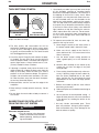
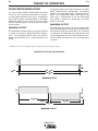
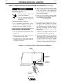
¥ Pierce the workpiece by slowly lowering the torch
onto the metal at a 30¡ angle away from the operator. This will blow the dross away from the torch tip.
Slowly rotate the torch to vertical position as the arc
becomes deeper.
TORCH AT 300 ANGLE
TO PIERCE
5ϒ - 15ϒ Leading Angle
Direction of Travel
10ϒ - 20ϒ Arc Lag
¥ Finish the cut to be made and release the trigger.
¥ When the trigger is released, the arc will stop.
- The gas will continue to flow for 10 seconds of
postflow. If the trigger is activated within this time
period, the pilot arc will immediately restart.
¥ If the dross is difficult to remove, reduce the cutting
speed. High speed dross is more difficult to remove
than low speed dross.
¥ The right side of the cut is more square than the left
as viewed along the direction of travel.
¥ Clean spatter and scale from the nozzle and drag
cup frequently.
¥ For gouging, tilt the torch about 45¡ from the workpiece and hold the nozzle 1/8 in. (3.2mm) to 3/16Ó
(4.7mm) above the workpiece.
ANGLE
OF APPROACH
ROTATE TO
0
90 ANGLE TO CUT
300
900
VERTICAL ANGLE
VERTICAL
FOR CUTTING
TORCH HELD AT
450 ANGLE
THROUGHOUT GOUGE
CUT
¥ Hold the nozzle standoff 1/8 in. (3.2mm) to 3/16 in.
(4.7mm) above the workpiece during cutting. Do not
let the torch nozzle touch the work or carry a long
arc.
¥ Keep moving while cutting. Cut at a steady speed
without pausing. Maintain the cutting speed so that
the arc lag is 10¡ to 20¡ behind the travel direction.
¥ Use a 5¡ - 15¡ leading angle in the direction of the cut.
¥ Use the drag cup to maintain constant standoff for
better cut quality and to protect the nozzle from
spatter.
ANGLE
MAINTAINED
THROUGHOUT
GOUGE
SAFETY STATUS INDICATOR
¥ If the "SAFETY" status indicators light at any time,
check the following:
- Check the assembly of the torch consumables. If
they are not properly in place, the machine will not
start. Make sure that the shield cup is hand
tight. Do not use pliers or overtighten.
¥ Use the drag cup with a metal template to prevent
nozzle double arcing.
PRO-CUT 80
B-7
B-7
OPERATION
PREHEAT TEMPERATURE FOR
PLASMA CUTTING
WARNING
ELECTRIC SHOCK can kill.
¥ Turn off machine at the disconnect switch on the front of the
machine before tightening,
cleaning or replacing consumables.
- Check the conditions of the inside of the nozzle. If
debris has collected, rub the electrode on the
inside bottom of the nozzle to remove any oxide
layer that may have built up. Refer to
ÒSuggestions for Extra Utility from the Pro-Cut
System.Ó
- Check the condition of the electrode. If the end has
a crater-like appearance, replace it along with the
nozzle. The maximum wear depth of the electrode
is approximately .062 in. (1.6mm). A green and
erratic arc will indicate definite electrode failure.
The electrode should be replaced immediately.
¥ Replace the nozzle when the orifice exit is eroded
away or oval shaped.
¥ After the problem is found, or if there is nothing
apparently wrong, reset the machine by pressing
the "Reset" button. (It is possible for electrical noise
to trip the safety circuit on rare occasions. This
should not be a regular occurrence.)
Preheat temperature control is not necessary in most
applications when plasma arc cutting or gouging.
Preheat temperature control may be necessary on
high carbon alloy steels and heat treated aluminum for
crack resistance and hardness control. Job conditions, prevailing codes, alloy level, and other considerations may also require preheat temperature control.
The recommended minimum preheat temperature for
plate thickness up to 1/2 in. (12.7mm) is 70¡ F (21.1¡ C).
Higher temperatures may be used as required by the
job conditions and/or prevailing codes. If cracking or
excessive hardness occurs on the cut face, higher preheat temperature may be required.
PROCEDURE RECOMMENDATIONS
When properly used, plasma arc cutting or gouging is
a very economical process. Improper use will result in
a very high operating cost.
GENERAL - IN ALL CASES
¥ Follow safety precautions as printed throughout this
manual and on the machine.
THIN GAUGE SHEET METAL
¥ If the machine does not reset or continues to trip,
consult the Troubleshooting Section.
Torch Standoff
Machine Output Setting
¥ Use the proper cutting or gouging procedures
referred to in ÒProcedure RecommendationsÓ
below.
45
USER RESPONSIBILITY
Because design, fabrication, erection, and cutting variables affect results, the serviceability of a product or
structure is the responsibility of the user. Variation
such as plate chemistry, plate surface condition (oil,
scale), plate thickness, preheat, quench, gas type, gas
flow rate and equipment may produce results different
from those expected. Some adjustments to procedures may be necessary to compensate for unique
individual conditions. Test all procedures duplicating
actual field conditions.
DRAG thru 1/16"
Standoff
Output Setting
Min. thru Mid. Range
Output set below 45 Amps.
¥ The nozzle may be dragged on the metal surface,
touching it lightly to the surface after piercing a hole.
Current control should be set below the mid-range.
¥ Do not allow cable or body to contact hot surface.
PRO-CUT 80
B-8
OPERATION
THICK SECTIONS OF METAL
Torch Standoff
Machine Output Setting
45
1/8" thru 3/16"
Standoff
Output Setting
Mid. thru Max. Range
Output set above 45 Amps.
B-8
1. Occasionally an oxide layer may form over the tip
of the electrode, creating an insulating barrier
between the electrode and nozzle. This will result in
the tripping of the Pro-Cut's safety circuit. When
this happens, turn the power off, remove the nozzle and electrode and use the electrode to rub
against the inside bottom surface of the nozzle.
This will help remove any oxide buildup. Replace
the nozzle, turn on the power and continue cutting.
If the Parts-in-Place circuit (safety status indicator
light) continues to trip after cleaning the consumables, replace them with a new set. Do not continue to cut with excessively worn consumables as
this can cause damage to the torch head and will
degrade cut quality.
2. To improve consumable life, here are some suggestions that may be useful:
¥ The best quality and consumable life will be
obtained by holding the torch off the surface about
3/16 in. (4.7mm). Too long an arc may compromise
cut quality and consumable life. The nozzle should
NOT be dragged on the work.
a. Never drag the nozzle on the work surface if
the output control knob is above 45 Amps.
¥ Use of the S22151 Drag Cup will maintain the proper standoff. The only time not to use the drag cup
when the output control is set above mid-range is in
special, tight corners. Always hold at least a 1/8 in.
(3.2mm) standoff in those situations.
c. Use the lowest output setting possible to
make a good quality cut at the desired cut
speed.
¥ If piercing is required, slowly lower the torch at an
angle of about 30¡ to blow the dross away from the
torch tip and slowly rotate the torch to a vertical
position as the arc becomes deeper. This process
will blow a lot of molten metal and dross. Be careful! Blow the dross away from the torch, the operator and any flammable objects.
¥ Where possible, start the cut from the edge of the
workpiece.
¥ Keep moving! A steady speed is necessary. Do not
pause.
¥ Do not allow the torch cable or body to contact a
hot surface.
SUGGESTIONS FOR EXTRA UTILITY
FROM THE PRO-CUT SYSTEM
WARNING
ELECTRIC SHOCK can kill.
¥ Turn off machine at the disconnect
switch on the front of the machine
before tightening, cleaning or replacing consumables.
b. Make sure the air supply to the Pro-Cut is
clean and free of oil. Use several extra in-line
filters if necessary.
d. Minimize dross buildup on the nozzle tip by
starting the cut from the edge of the plate
when possible.
e. Pierce cutting should be done only when necessary. If piercing, angle the torch about 30¡
from the plane perpendicular to the workpiece, transfer the arc, then bring the torch
perpendicular to the work and begin parallel
movement.
f. Reduce the number of pilot arc starts without
transferring to the work.
g. Reduce the pilot arc time before transferring to
the work.
h. Set air pressure to recommended setting. A
higher or lower pressure will cause turbulence
in the plasma arc, eroding the orifice of the
nozzle tip.
i. Use only Lincoln consumable parts. These
parts are patented. Using any other replacement consumables may cause damage to the
torch or reduce cut quality.
PRO-CUT 80
B-9
OPERATION
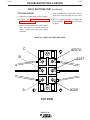
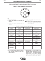
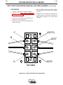
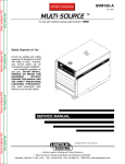
MACHINE INTERFACE
The PRO-CUT 80 comes standard with a machine
interface. Interface signals provided include: arc start,
arc initiated, and arc voltage. These signals are accessible through the 14 pin MS connector on the case
front.
ARC START:
The Arc Start circuit allows for triggering of the power
source to commence cutting. This circuit can be
accessed through pins K and M of the 14 pin MS connector. The circuit has a 17 VDC nominal open circuit
voltage and requires a dry contact closure to activate.
ARC INITIATED:
The Arc Initiated circuit provides information as to
when a cutting arc has transferred to the work piece.
This circuit can be accessed through pins I and J of the
14 pin MS connector. The circuit provides a dry contact
closure when the arc has transferred. Input to this circuit should be limited to 0.3 A for either 120VAC or
30VDC.
ARC VOLTAGE:
The Arc Voltage circuit can be used for activating a
torch height control. This circuit can be accessed
through pins D and G of the 14 pin MS connector. The
circuit provides full electrode to work arc voltage (no
voltage divider, 335VDC maximum).
Arc Start
K=2A
Arc Initiated
J=347
M=4A
I=348
L
H
C
N
G=343
D=344
F
E
Arc Voltage
14-PIN BOX RECEPTACLE, FRONT VIEW
Users wishing to utilize the Machine Interface can
order a K867 Universal Adapter (please adhere to the
pin locations stated above) or manufacture a 14 pin MS
connector cable assembly.
PRO-CUT 80
B-9
B-10
NOTES
PRO-CUT 80
B-10
Section C-1
Section C-1
TABLE OF CONTENTS
- ACCESSORIES Accessories...........................................................................................................................Section C
Options/Accessories...................................................................................................................C-2
PRO-CUT 80
C-2
ACCESSORIES
GENERAL OPTIONS /
ACCESSORIES
C-2
ALWAYS USE GENUINE LINCOLN ELECTRIC
ELECTRODES AND VORTECHª NOZZLES
The following options/accessories are available for
your PRO-CUT 80 from your local Lincoln Distributor.
K1681-1 Undercarriage - A valet style undercarriage
with pull-out handle for machine only. Provides torch
and work cable storage.
¥ Only Genuine Lincoln Electric consumables yield
the best cutting performance for the PRO-CUT 80.
¥ The patent pending VORTECHª nozzle pr ovides
an extra ÒkickÓ of swirl as the ar
c exits the nozzle,
which improves cutting performance. No other nozzle has this capability or can match its performance.
S22147-043 - Vortechª nozzle with an .043Ó (1.2 mm)
Orifice (For 35 - 60 Amps)
S22147-053 - Vortechª nozzle with an .053Ó (1.3 mm)
Orifice (For 60 - 85 Amps)
S22147-082 - VortechTM nozzle with an .082Ó (2.1 mm)
Orifice (For Gouging at 60 -85 Amps)
S22149 - Electrode - replacement electrodes for cutting.
S22150 - Shield Cup - This shields the torch tip and
provides more visibility to the workpiece than the drag
cup. Note the shield cup does not prevent the torch tip
from touching the workpiece.
S22151 - Drag Cup - The drag cup protects the torch
by preventing the torch from touching the workpiece.
K1571 Series - PCT 80 Torches come in 25Õ and 50Õ
lengths in either hand held or mechanized versions.
PRO-CUT 80
Section D-1
Section D-1
TABLE OF CONTENTS
-MAINTENANCEMaintenance .........................................................................................................................Section D
Safety Precautions......................................................................................................................D-2
Input Filter Capacitor Discharge Procedure ...............................................................................D-2
Routine Maintenance..................................................................................................................D-3
Periodic Maintenance .................................................................................................................D-3
Major Component Locations .....................................................................................................D-4
PRO-CUT 80
D-2
D-2
MAINTENANCE
4. Obtain a high resistance and high wattage resistor
(25-1000 ohms and 25 watts minimum). This resistor is not supplied with machine. NEVER USE A
SHORTING STRAP FOR THIS PROCEDURE.
WARNING
ELECTRIC SHOCK can kill.
¥ Have an electrician install and service
this equipment.
¥ Turn the input power off at the fuse box
before working on equipment.
¥ Do not touch electrically hot parts.
¥ Prior to performing preventative maintenance, perform the following capacitor discharge procedure to
avoid electric shock.
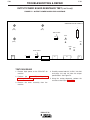
5. Locate the two capacitor terminals (large hex head
cap screws) at the bottom of the Power Board
shown in Figure D.1.
6. Use electrically insulated gloves and insulated pliers. Hold the body of the resistor and connect
resistor leads across the two capacitor terminals.
Hold the resistor in place for 10 seconds. DO NOT
TOUCH CAPACITOR TERMINALS WITH YOUR
BARE HANDS.
7. Repeat the discharge procedure for the other
capacitor.
INPUT FILTER CAPACITOR
DISCHARGE PROCEDURE
1. Turn off input power or disconnect input power
lines.
2. Remove the 5/16 in. hex head screws from the side
and top of the machine and remove wrap-around
machine cover.
8. Check voltage across the terminals of all capacitors with a DC voltmeter. Polarity of capacitor terminals is marked on the Power Board above terminals. Voltage should be zero. If any voltage
remains, repeat this capacitor discharge procedure.
3. Be careful not to make contact with the capacitor
terminals that are located on the top and bottom of
the Power Board on the right side of the machine.
FIGURE D.1 Ñ LOCA TION OF INPUT FILTER CAPACITOR TERMINALS
POWER
BOARD
CAPACITOR
TERMINALS
POWER
RESISTOR
RIGHT SIDE OF MACHINE
INSULATED
GLOVES
PRO-CUT 80
INSULATED
PLIERS
D-3
D-3
MAINTENANCE
ROUTINE MAINTENANCE
PERIODIC MAINTENANCE
1. Keep the cutting or gouging area and the area
around the machine clean and free of combustible
materials. No debris should be allowed to collect
which could obstruct air flow to the machine.
WARNING
ELECTRIC SHOCK can kill.
2. Every 6 months or so, the machine should be
cleaned with a low pressure airstream. Keeping the
machine clean will result in cooler operation and
higher reliability. Be sure to clean these areas. SEE
FIGURE D.2
- Power, Output and Control printed circuit boards
and heat sinks
• Turn off machine at the disconnect
switch on the front of the machine
before tightening, cleaning or replacing
consumables.
Change consumables as required.
- Power Switch
1. Thermal Protection
- Main Transformer
- Input Rectifier
3. Examine the sheet metal case for dents or breakage. Repair the case as required. Keep the case in
good condition to insure that high voltage parts are
protected and correct spacings are maintained. All
external sheet metal screws must be in place to
insure case strength and electrical ground continuity.
4. Check the air regulator filter to be sure it does not
become clogged. The air filter on the machine is
self draining and will not have to be emptied.
5. Check the filter element every several months to
see if it is clogged (weekly in very dirty environments). Replace if necessary by first removing the
two screws that attach the filter cage to the back
panel assembly, then slide the cage away from the
back of the machine and remove. Next, twist the
clear filter bowl until it comes off (be careful not to
lose the o-ring seated at the top of the bowl
threads). Unscrew the filter element and replace
with new element. Assemble parts in reverse order
as described above.
6. Inspect the cable periodically for any slits or puncture marks in the cable jacket. Replace if necessary. Check to make sure that nothing is crushing
the cable and blocking the flow of air through the
air tube inside. Also, check for kinks in the cable
periodically and relieve any so as not to restrict the
flow of air to the torch.
Two thermostats protect the machine from excessive
operating temperatures. Excessive temperatures may
be caused by a lack of cooling air or by operating the
machine beyond the duty cycle and output rating. If
excessive operating temperatures should occur, the
yellow thermal LED will light and the thermostat will
prevent output voltage or current.
Thermostats are self-resetting once the machine cools
sufficiently. If the thermostat shutdown was caused by
excessive output or duty cycle and the fan is operating normally, the Power Switch may be left on and the
reset should occur within a 15 minute period. If the fan
is not turning or the air intake louvers were obstructed,
then the power must be switched off and the fan problem or air obstruction must be corrected.
2. Filter Capacitor Conditioning (PRO-CUT 80, 400460 VAC only)
A protection circuit is included to monitor the voltage
across filter capacitors C1 and C2. In the event that
the capacitor voltage is too high, the protection circuit
will prevent output. The protection circuit may prevent
output providing all these circumstances are met:
a. Machine is connected
460-575 VAC input.
for
400-460
or
b. Machine did not have power applied for many
months.
c. Machine will not produce output when power is
first switched on.
If these circumstances apply, the proper action is to
switch the machine on and let it idle for up to 30 minutes. This is required to condition the filter capacitors
after an extended storage time. The protection circuit
will automatically reset once the capacitor conditioning and resultant voltage levels are acceptable. It may
be necessary to turn the power switch off and back on
again after this period.
PRO-CUT 80
D-4
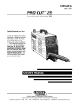
D-4
Maintenance
FIGURE D.2 Ð MAJOR COMPONENT LOCATIONS
1. Case Front
2. Base and Case Back
3. Center Panel Assembly
4. Output Board Heatsink
5. Power Board Assembly
6. Case Wraparound
6
4
3
5
1
2
PRO-CUT 80
Section E-1
Section E-1
TABLE OF CONTENTS
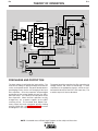
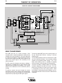
-THEORY OF OPERATION SECTIONTheory of Operation .............................................................................................................Section E
General Description ....................................................................................................................E-2
Input Line Voltage, Contactor and Main Transformer.................................................................E-2
Precharge and Protection ...........................................................................................................E-3
Main Transformer ........................................................................................................................E-4
Output Board and Torch .............................................................................................................E-5
Control and Display Boards........................................................................................................E-6
Protection Circuits ......................................................................................................................E-7
Overload Protection..............................................................................................................E-7
Thermal Protection ...............................................................................................................E-7
Insulated Gate Bipolar Transistor (IGBT) Operation ...................................................................E-8
Pulse Width Modulation (PWM) ..................................................................................................E-9
Minimum Output...................................................................................................................E-9
Maximum Output..................................................................................................................E-9
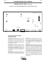
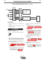
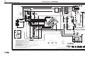
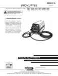
FIGURE E.1 – PRO-CUT 80 BLOCK LOGIC DIAGRAM
WORK
NOZZLE
ELECTRODE
POWER BOARD
MAIN
TRANSFORMER
CR 1&2
RELAY
INPUT
LINE
SWITCH
OUTPUT
TORCH
CONNECTOR
BOARD
E
L
E
C
T
R
O
D
E
IGBT
INPUT
RECTIFIER
CAPACITOR
CHOKE
R
E
C
O
N
N
E
C
T
PILOT
TRANSISTOR
IGBT
D
IGBT
CURRENT
TRANSFORMER
S
W
I
T
C
H
S
O
L
E
N
O
I
TRIGGER & SAFETY
CAPACITOR
AIR
SOLENOID
IGBT
AIR
PRESSURE
SWITCH
"A"
L
E
P
R
O
T
E
C
T
I
O
N
TRIGGER & SAFETY
CR 1 & 2
RELAY
DRIVE
SIGNAL
REMOTE
INTERFACE
RECEPTACLE
IGBT
GATE
SIGNALS
ELECTRODE & TRANSFER
CURRENT FEEDBACK
SIGNAL
A
PILOT ENABLE
CONTROL BOARD
ELECTRODE SOLENOID ENABLE
D
AIR SOLENOID ENABLE
18/36VAC
THERMOSTATS
R
E
A
D
Y
A
I
R
L
O
W
T
H
E
R
M
A
L
S
A
F
E
T
Y
OUTPUT
CONTROL
DISPLAY BOARD
12VAC
24VAC
115VAC
AUXILIARY
TRANSFORMER
FAN
MOTOR
PRO-CUT 80
E-2
E-2
THEORY OF OPERATION
FIGURE E.2 Ð INPUT LINE VOLTAGE
WORK
NOZZLE
ELECTRODE
POWER BOARD
MAIN
TRANSFORMER
CR 1&2
RELAY
INPUT
LINE
SWITCH
OUTPUT
TORCH
CONNECTOR
BOARD
E
L
E
C
T
R
O
D
E
IGBT
INPUT
RECTIFIER
CAPACITOR
CHOKE
R
E
C
O
N
N
E
C
T
PILOT
TRANSISTOR
IGBT
D
IGBT
CURRENT
TRANSFORMER
S
W
I
T
C
H
S
O
L
E
N
O
I
TRIGGER & SAFETY
CAPACITOR
AIR
SOLENOID
IGBT
"A"
AIR
PRESSURE
SWITCH
L
E
P
R
O
T
E
C
T
I
O
N
TRIGGER & SAFETY
CR 1 & 2
RELAY
DRIVE
SIGNAL
REMOTE
INTERFACE
RECEPTACLE
IGBT
GATE
SIGNALS
ELECTRODE & TRANSFER
CURRENT FEEDBACK
SIGNAL
A
PILOT ENABLE
CONTROL BOARD
D
ELECTRODE SOLENOID ENABLE
AIR SOLENOID ENABLE
18/36VAC
THERMOSTATS
R
E
A
D
Y
A
I
R
L
O
W
T
H
E
R
M
A
L
S
A
F
E
T
Y
OUTPUT
CONTROL
DISPLAY BOARD
12VAC
24VAC
115VAC
AUXILIARY
TRANSFORMER
FAN
MOTOR
GENERAL DESCRIPTION
The PRO-CUT 80 is a constant current, continuous
control plasma cutting power source. The inverter
based power supply design is controlled by a microprocessor control board. The control system has a
safety mechanism to insure that the nozzle and electrode are in place before cutting or gouging. The PROCUT 80 initiates the plasma arc with a simple, yet reliable, touch start mechanism. This system eliminates
many of the problems associated with hi-frequency
type start systems. When powered up, the machine
performes some rudimentary self diognostics.
INPUT LINE VOLTAGE, SWITCH
AND MAIN TRANSFORMER
The single-phase or three-phase input power is connected to the machine, via an input line cord, to a
switch located on the front panel.
A reconnect panel and voltage range switch allow the
user to configure the machine for either a low or high
input voltage and also connect the auxiliary transformer for the appropriate input voltage.
The auxiliary transformer develops the appropriate AC
voltages to operate the cooling fan, the control board
and the plasma output board.
NOTE: Unshaded areas of Block Logic Diagram are the subject of discussion.
PRO-CUT 80
E-3
E-3
THEORY OF OPERATION
WORK
NOZZLE
ELECTRODE
POWER BOARD
MAIN
TRANSFORMER
CR 1&2
RELAY
INPUT
LINE
SWITCH
OUTPUT
TORCH
CONNECTOR
BOARD
E
L
E
C
T
R
O
D
E
IGBT
INPUT
RECTIFIER
CAPACITOR
CHOKE
R
E
C
O
N
N
E
C
T
PILOT
TRANSISTOR
IGBT
D
IGBT
CURRENT
TRANSFORMER
S
W
I
T
C
H
S
O
L
E
N
O
I
TRIGGER & SAFETY
CAPACITOR
AIR
SOLENOID
IGBT
"A"
AIR
PRESSURE
SWITCH
L
E
P
R
O
T
E
C
T
I
O
N
TRIGGER & SAFETY
CR 1 & 2
RELAY
DRIVE
SIGNAL
REMOTE
INTERFACE
RECEPTACLE
IGBT
GATE
SIGNALS
ELECTRODE & TRANSFER
CURRENT FEEDBACK
SIGNAL
A
PILOT ENABLE
CONTROL BOARD
D
ELECTRODE SOLENOID ENABLE
AIR SOLENOID ENABLE
18/36VAC
THERMOSTATS
R
E
A
D
Y
A
I
R
L
O
W
T
H
E
R
M
A
L
S
A
F
E
T
Y
OUTPUT
CONTROL
DISPLAY BOARD
12VAC
24VAC
115VAC
AUXILIARY
TRANSFORMER
FAN
MOTOR
PRECHARGE AND PROTECTION
The input voltage is rectified by the input rectifier. The
resultant DC voltage is applied, through the reconnect
switch, to the power board. The power board contains
precharging circuitry for the safe charging of the input
filter capacitors. Once the capacitors are precharged
and balanced the control board activates the CR1+
CR2 input relays. This connects full input power to the
filter capacitors. When the filter capacitors are fully
charged they act as power supplies for the IGBT
switching circuit. The Insulated Gate Bipolar Transistors supply the main transformer primary winding
with DC current flow. See IGBT Operation discussion
and diagrams in this section.
The power board also monitors the filter capacitors for
voltage balance and under or overvoltage. If either
should occur, the appropriate signal is sent to the control board to deactivate the CR1+ CR2 input relay. The
machine output will also be disabled.
NOTE: Unshaded areas of Block Logic Diagram are the subject of discussion.
PRO-CUT 80
E-4
E-4
THEORY OF OPERATION
FIGURE E.4 Ð MAIN TRANSFORMER
WORK
NOZZLE
ELECTRODE
POWER BOARD
MAIN
TRANSFORMER
CR 1&2
RELAY
INPUT
LINE
SWITCH
OUTPUT
TORCH
CONNECTOR
BOARD
E
L
E
C
T
R
O
D
E
IGBT
INPUT
RECTIFIER
CAPACITOR
CHOKE
R
E
C
O
N
N
E
C
T
PILOT
TRANSISTOR
IGBT
D
IGBT
CURRENT
TRANSFORMER
S
W
I
T
C
H
S
O
L
E
N
O
I
TRIGGER & SAFETY
CAPACITOR
AIR
SOLENOID
IGBT
"A"
AIR
PRESSURE
SWITCH
L
E
P
R
O
T
E
C
T
I
O
N
TRIGGER & SAFETY
CR 1 & 2
RELAY
DRIVE
SIGNAL
REMOTE
INTERFACE
RECEPTACLE
IGBT
GATE
SIGNALS
ELECTRODE & TRANSFER
CURRENT FEEDBACK
SIGNAL
A
PILOT ENABLE
CONTROL BOARD
D
ELECTRODE SOLENOID ENABLE
AIR SOLENOID ENABLE
18/36VAC
THERMOSTATS
R
E
A
D
Y
A
I
R
L
O
W
T
H
E
R
M
A
L
S
A
F
E
T
Y
OUTPUT
CONTROL
DISPLAY BOARD
12VAC
24VAC
115VAC
AUXILIARY
TRANSFORMER
FAN
MOTOR
MAIN TRANSFORMER
Each IGBT pair acts as a switch assembly. Each
assembly feeds a separate, oppositely wound primary
winding of the main transformer. The reverse direction
of current flow through the main transformer primaries
and the offset timing of the IGBT pairs induce an AC
square wave output signal at the secondary of the
main transformer.
The DC current flow through each primary winding is
redirected or "clamped" back to each respective filter
capacitor when the IGBTs are turned off. This is needed due to the inductance of the transformer primary
winding.
The primary currents also pass through the current
transformer, which sends a signal to the control board.
If the primary currents are not equal, the control board
compensates by adjusting the IGBT gate signals.
The firing of both IGBT pairs occurs during halves of
the 50 microsecond intervals, creating a constant
20KHZ output.
The secondary portion of the main transformer is made
up of two separate windings. One secondary winding
supplies the electrode-to-work voltage. This is the
high current winding, which is capable of supplying
maximum output current during the cutting process.
The other secondary winding supplies the electrodeto-nozzle voltage for the pilot arc current. The conductor in this winding is smaller since the pilot current
is considerably less than the cutting current. While
one winding is conducting the other winding is at a limited voltage and aids in the arc transfer to and from the
workpiece.
PRO-CUT 80
E-5
E-5
THEORY OF OPERATION
FIGURE E.5 Ð PLASMA OUTPUT BOARD AND TORCH
WORK
NOZZLE
ELECTRODE
POWER BOARD
MAIN
TRANSFORMER
CR 1&2
RELAY
INPUT
LINE
SWITCH
OUTPUT
TORCH
CONNECTOR
BOARD
E
L
E
C
T
R
O
D
E
IGBT
INPUT
RECTIFIER
CAPACITOR
CHOKE
R
E
C
O
N
N
E
C
T
PILOT
TRANSISTOR
IGBT
D
IGBT
CURRENT
TRANSFORMER
S
W
I
T
C
H
S
O
L
E
N
O
I
TRIGGER & SAFETY
CAPACITOR
AIR
SOLENOID
IGBT
"A"
AIR
PRESSURE
SWITCH
L
E
P
R
O
T
E
C
T
I
O
N
TRIGGER & SAFETY
CR 1 & 2
RELAY
DRIVE
SIGNAL
REMOTE
INTERFACE
RECEPTACLE
IGBT
GATE
SIGNALS
ELECTRODE & TRANSFER
CURRENT FEEDBACK
SIGNAL
A
PILOT ENABLE
CONTROL BOARD
D
ELECTRODE SOLENOID ENABLE
AIR SOLENOID ENABLE
18/36VAC
R
E
A
D
Y
THERMOSTATS
A
I
R
L
O
W
T
H
E
R
M
A
L
S
A
F
E
T
Y
OUTPUT
CONTROL
DISPLAY BOARD
12VAC
24VAC
115VAC
AUXILIARY
TRANSFORMER
FAN
MOTOR
OUTPUT BOARD AND TORCH
The output board contains an Insulated Gate Bipolar
Transistor (IGBT) which, upon receiving a pilot signal from
the control board, either enables or disables the current in
the pilot winding. The cutting and pilot rectifier diodes are
also incorporated in the output board. There are two
diodes for the pilot winding and four diodes for the cutting
winding.
There are two P.C. board mounted current sensors. One
sensor regulates pilot and cutting current. The other sensor indicates to the control board when and how much
current transfers to the workpiece.
The output board also includes the trigger circuitry, the gas
solenoid driver, the electrode solenoid driver and the torch
parts-in-place circuitry and remote interface circutry.
The output choke, which is in series with both the pilot circuit and the cutting circuit, provides current filtering to
enhance arc stability.
The PCT 80 torch uses a patented touch start mechanism
that provides superior starting performance over other
touch start systems. The torch head consists of 3 major
parts: torch body, insulator and piston. The insulator provides an electrical barrier between the piston and torch
body. The piston provides a path for electrical current to
the electrode. The piston also drives the electrode to the
nozzle for arc initiation. The torch body contains the main
torch components: the trigger, pilot arc, cutting arc, and air
flow systems are included.
A copper nozzle with a patented internal swirl is used to
focus the arc. A small, precise hole in the end of the nozzle constricts the arc and increases the current density.
As the air enters the torch head, it is directed between
the electrode and nozzle for maximum electrode cooling.
A portion of the cooling air exits the chamber through
vents in the side of the nozzle. A swirl texture located
inside the bottom of the nozzle increases the plenum air
swirl strength, and improves arc start reliability and partsin-place verification.
Plasma arc initiation occurs as follows: First, in the idle
state, a spring inside the torch head pushes the piston
and electrode forward to make continuity with the nozzle.
When the trigger is pulled, air flow begins and creates
enough back force on the electrode to overcome the
force of the spring. However, the solenoid valve allows
enough forward force on the piston to maintain continuity between the consumables. After this continuity has
been verified by the Pro-CutÕ
s parts-in-place circuit, output current is established and regulated. Once the current stabilizes, the solenoid valve turns off, removing the
forward force on the piston. The back pressure drives
the piston and electrode away from the nozzle, creating
the plasma arc. The air stream forces the arc out the orifice of the nozzle. This appears as a pilot arc, which can
then be transferred for cutting.
PRO-CUT 80
E-6
E-6
THEORY OF OPERATION
FIGURE E.6 Ð CONTROL AND DISPLAY BOARDS
WORK
NOZZLE
ELECTRODE
POWER BOARD
MAIN
TRANSFORMER
CR 1&2
RELAY
INPUT
LINE
SWITCH
OUTPUT
TORCH
CONNECTOR
BOARD
E
L
E
C
T
R
O
D
E
IGBT
INPUT
RECTIFIER
CAPACITOR
CHOKE
R
E
C
O
N
N
E
C
T
PILOT
TRANSISTOR
IGBT
D
IGBT
CURRENT
TRANSFORMER
S
W
I
T
C
H
S
O
L
E
N
O
I
TRIGGER & SAFETY
CAPACITOR
AIR
SOLENOID
IGBT
"A"
AIR
PRESSURE
SWITCH
L
E
P
R
O
T
E
C
T
I
O
N
TRIGGER & SAFETY
CR 1 & 2
RELAY
DRIVE
SIGNAL
REMOTE
INTERFACE
RECEPTACLE
IGBT
GATE
SIGNALS
ELECTRODE & TRANSFER
CURRENT FEEDBACK
SIGNAL
A
PILOT ENABLE
CONTROL BOARD
D
ELECTRODE SOLENOID ENABLE
AIR SOLENOID ENABLE
18/36VAC
THERMOSTATS
R
E
A
D
Y
A
I
R
L
O
W
T
H
E
R
M
A
L
S
A
F
E
T
Y
OUTPUT
CONTROL
DISPLAY BOARD
12VAC
24VAC
115VAC
AUXILIARY
TRANSFORMER
FAN
MOTOR
CONTROL AND DISPLAY BOARDS
The control board receives status and analog feedback signals from the output board, display board,
power board and various sensors. The processor
interprets these signals, makes decisions and changes
machine mode and output to satisfy the requirements
as defined by the internal software. The control board
regulates the output of the machine by controlling the
IGBT switching times through pulse width modulation
circuitry. See Pulse Width Modulation in this section.
The display board receives commands from the control board and, via indicator lights, communicates
PRO-CUT 80 status and operating conditions to the
user.
PRO-CUT 80
E-7
THEORY OF OPERATION
E-7
PROTECTION CIRCUITS
THERMAL PROTECTION
Protection circuits are designed into the PRO-CUT 80
machine to sense trouble and shut down the machine
before the trouble damages internal machine components. Both overload and thermal protection circuits
are included.
Two thermostats protect the machine from excessive
operating temperatures. One thermostat is located on
the output choke and the other on the power board
IGBT heat sink. Excessive temperatures may be
caused by a lack of cooling air or by operating the
machine beyond the duty cycle and output rating. If
excessive operating temperatures should occur, the
thermal status indicator will light and the thermostat
will prevent output voltage or current.
OVERLOAD PROTECTION
The PRO-CUT 80 is electrically protected from producing higher than normal output currents. If the output current exceeds 85-90 amps, an electronic protection circuit limits the current to within the capabilities of the machine.
Another protection circuit monitors the voltage across
the input filter capacitors. If the filter capacitor voltage
is too high, too low or not balanced the protection circuit may prevent machine output.
Thermostats are self-resetting once the machine cools
sufficiently. If the thermostat shutdown was caused
by excessive output or duty cycle and the fan is operating normally, the power switch may be left on and
the reset should occur within a 15 minute period. If
the fan is not turning or the air intake louvers are
obstructed, the input power must be removed and the
fan problem or air obstruction must be corrected.
PRO-CUT 80
E-8
E-8
THEORY OF OPERATION
INSULATED GATE BIPOLAR
TRANSISTOR (IGBT) OPERATION
An IGBT is a type of transistor. IGBTs are semiconductors well suited for high frequency switching and
high current applications.
Drawing A shows an IGBT in a passive mode. There
is no gate signal, zero volts relative to the source, and
therefore, no current flow. The drain terminal of the
IGBT may be connected to a voltage supply; but since
there is no conduction the circuit will not supply current to components connected to the source. The circuit is turned off like a light switch in the OFF position.
Drawing B shows the IGBT in an active mode. When
the gate signal, a positive DC voltage relative to the
source, is applied to the gate terminal of the IGBT, it
is capable of conducting current. A voltage supply
connected to the drain terminal will allow the IGBT to
conduct and supply current to circuit components
coupled to the source. Current will flow through the
conducting IGBT to downstream components as long
as the positive gate signal is present. This is similar
to turning ON a light switch.
FIGURE E.7 Ð CONTROL AND DISPLAY BOARDS
POSITIVE
VOLTAGE
APPLIED
SOURCE
n+
GATE
SOURCE
n+
n+
GATE
n+
p
BODY REGION
p
BODY REGION
n-
DRAIN DRIFT REGION
n-
DRAIN DRIFT REGION
n+
BUFFER LAYER
n+
BUFFER LAYER
p+
INJECTING LAYER
p+
INJECTING LAYER
DRAIN
DRAIN
B. ACTIVE
A. PASSIVE
PRO-CUT 80
E-9
THEORY OF OPERATION
PULSE WIDTH MODULATION
The term PULSE WIDTH MODULATION describes
how much time is devoted to conduction in the positive and negative portions of the cycle. Changing the
pulse width is known as MODULATION. Pulse Width
Modulation (PWM) is the varying of the pulse width
over the allowed range of a cycle to affect the output
of the machine.
MINIMUM OUTPUT
By controlling the duration of the gate signal, the IGBT
is turned on and off for different durations during a
cycle. The top drawing below shows the minimum
output signal possible over a 50-microsecond time
period.
1
E-9
The positive portion of the signal represents one IGBT
group1 conducting for 1 microsecond. The negative
portion is the other IGBT group1. The dwell time (off
time) is 48 microseconds (both IGBT groups off).
Since only 2 microseconds of the 50-microsecond
time period is devoted to conducting, the output
power is minimized.
MAXIMUM OUTPUT
By holding the gate signals on for 22 microseconds
each and allowing only 3 microseconds of dwell time
(off time) during the 50-microsecond cycle, the output
is maximized. The darkened area under the top curve
can be compared to the area under the bottom curve.
The more dark area under the curve, the more power
is present.
An IGBT group consists of two IGBT modules feeding one transformer primary winding.
FIGURE E.8 Ð TYPICAL IGBT OUTPUTS
sec
48
50
sec
sec
sec
MINIMUM OUTPUT
22 sec
3 sec
50 sec
MAXIMUM OUTPUT
PRO-CUT 80
22 sec
E-10
NOTES
PRO-CUT 80
E-10
Section F-1
Section F-1
TABLE OF CONTENTS
TROUBLESHOOTING & REPAIR SECTION
Troubleshooting & Repair Section .................................................................................Section F
How to Use Troubleshooting Guide ......................................................................................F-2
PC Board Troubleshooting Procedures and Replacement ...................................................F-3
Troubleshooting Guide...........................................................................................................F-4
Test Procedures
Input Filter Capacitor Discharge Procedure..................................................................F-10
Input Rectifier Test ........................................................................................................F-12
Primary Power Board Resistance Test and Capacitor Voltage Test .............................F-15
Output Power Board Resistance Test...........................................................................F-20
Torch Continuity and Solenoid Test ..............................................................................F-23
Air/Gas Solenoid Test....................................................................................................F-25
T2 Auxiliary Transformer Test ........................................................................................F-27
Trigger Circuit Test ........................................................................................................F-30
Low Voltage Circuit Test................................................................................................F-35
Replacement Procedures
Control Board Removal and Replacement ...................................................................F-40
Display Board Removal and Replacement ...................................................................F-43
Output Power Board Removal and Replacement.........................................................F-46
Primary Power Board and Filter Capacitor Removal and Replacement ......................F-50
Input Rectifier Bridge Removal and Replacement........................................................F-54
Retest after Repair ........................................................................................................F-57
PRO-CUT 80
F-2
TROUBLESHOOTING & REPAIR
HOW TO USE TROUBLESHOOTING GUIDE
WARNING
Service and repair should be performed by only Lincoln Electric Factory Trained Personnel.
Unauthorized repairs performed on this equipment may result in danger to the technician and machine
operator and will invalidate your factory warranty. For your safety and to avoid Electrical Shock, please
observe all safety notes and precautions detailed throughout this manual.
This Troubleshooting Guide is provided to help
you locate and repair possible machine malfunctions. Simply follow the three-step procedure
listed below.
Step 1. LOCATE PROBLEM (SYMPTOM). Look
under the column labeled “PROBLEM (SYMPTOMS). This column describes possible symptoms that the machine may exhibit. Find the listing that best describes the symptom that the
machine is exhibiting. Symptoms are grouped
into four main categories: Output Problems,
Function Problems, Cutting Problems and LED
Function Problems.
Step 2. PERFORM EXTERNAL TESTS. The
second column, labeled “POSSIBLE AREAS OF
MISADJUSTMENT(S)”, lists the obvious external
possibilities that may contribute to the machine
symptom. Perform these tests/checks in the
order listed. In general, these tests can be conducted without removing the case wrap-around
cover.
Step 3. PERFORM COMPONENT TESTS. The
last column, labeled “Recommended Course of
Action” lists the most likely components that may
have failed in your machine. It also specifies the
appropriate test procedure to verify that the subject component is either good or bad. If there are
a number of possible components, check the
components in the order listed to eliminate one
possibility at a time until you locate the cause of
your problem.
All of the referenced test procedures referred to in
the Troubleshooting Guide are described in detail
at the end of this chapter. Refer to the
Troubleshooting and Repair Table of Contents to
locate each specific Test Procedure. All of the
referred to test points, components, terminal
strips, etc., can be found on the referenced electrical wiring diagrams and schematics. Refer to
the Electrical Diagrams Section Table of Contents
to locate the appropriate diagram.
CAUTION
If for any reason you do not understand the test procedures or are unable to perform the test/repairs
safely, contact the Lincoln Electric Service Department for electrical troubleshooting assistance before
you proceed. Call 1-800-833-9353.
PRO-CUT 80
F-2
F-3
TROUBLESHOOTING & REPAIR
F-3
PC BOARD TROUBLESHOOTING PROCEDURES
WARNING
ELECTRIC SHOCK can kill.
Have an electrician install and service
this equipment. Turn the machine OFF
before working on equipment. Do not
touch electrically hot parts.
Sometimes machine failures appear to be due to PC
board failures. These problems can sometimes be
traced to poor electrical connections. To avoid problems when troubleshooting and replacing PC boards,
please use the following procedure:
• Remove the PC Board from the static-shielding bag
and place it directly into the equipment. Don’t set
the PC Board on or near paper, plastic or cloth which
could have a static charge. If the PC Board can’t be
installed immediately, put it back in the staticshielding bag.
• If the PC Board uses protective shorting jumpers,
don’t remove them until installation is complete.
• If you return a PC Board to The Lincoln Electric
Company for credit, it must be in the static-shielding
bag. This will prevent further damage and allow
proper failure analysis.
4. Test the machine to determine if the failure symptom has been corrected by the replacement PC
board.
1. Determine to the best of your technical ability that
the PC board is the most likely component causing the failure symptom.
NOTE: Allow the machine to heat up so that all electrical components can reach their operating
temperature.
2. Check for loose connections at the PC board to
assure that the PC board is properly connected.
5. Remove the replacement PC board and substitute
it with the original PC board to recreate the original
problem.
3. If the problem persists, replace the suspect PC
board using standard practices to avoid static
electrical damage and electrical shock. Read the
warning inside the static resistant bag and perform
the following procedures:
a. If the original problem does not reappear
by substituting the original board, then the
PC board was not the problem. Continue
to look for bad connections in the control
wiring harness, junction blocks, and terminal strips.
PC Board can be damaged by
static electricity.
ATTENTION
Static-Sensitive
Devices
Handle only at
Static-Safe
Workstations
Reusable
Container
Do Not Destroy
• Remove your body’s static charge
before opening the static-shielding bag. Wear an anti-static wrist
strap. For safety, use a 1 Meg
ohm resistive cord connected to a
grounded part of the equipment
frame.
• If you don’t have a wrist strap,
touch an unpainted, grounded,
part of the equipment frame.
Keep touching the frame to prevent static build-up. Be sure not
to touch any electrically live parts
at the same time.
b. If the original problem is recreated by the
substitution of the original board, then the
PC board was the problem. Reinstall the
replacement PC board and test the
machine.
6. Always indicate that this procedure was followed
when warranty reports are to be submitted.
NOTE: Following this procedure and writing on the
warranty report, “INSTALLED AND SWITCHED
PC BOARDS TO VERIFY PROBLEM,” will help
avoid denial of legitimate PC board warranty
claims.
• Tools which come in contact with the PC Board must
be either conductive, anti-static or static-dissipative.
PRO-CUT 80
F-4
F-4
TROUBLESHOOTING & REPAIR
TROUBLESHOOTING GUIDE
Observe Safety Guidelines
detailed in the beginning of this manual.
PROBLEMS
(SYMPTOMS)
POSSIBLE AREAS OF
MISADJUSTMENT(S)
RECOMMENDED
COURSE OF ACTION
OUTPUT PROBLEMS
Major physical or electrical damage is evident when the sheet
metal cover(s) are removed.
1. Contact your local authorized
Lincoln Electric Field Service
Facility for technical assistance.
1. Contact the Lincoln Electric
Service Department,
Machine is dead – no output – no
fan – no status indicator lights.
1. Make sure that the input power
switch is in the “ON” position.
1. Check the input power switch
(S1) for proper operation. See
the Wiring Diagram.
2. Check the input voltage at the
machine. Input voltage must
match the rating plate and the
reconnect panel.
3. Check for blown or missing
fuses in the input lines and the
0.6 amp slow blow reconnect
fuse.
Machine is dead - not output - no
status indicator lights - fans run.
1. Check the input voltage at the
machine. Input voltage must
match the rating plate and the
reconnect panel.
1-800-833-9353 (WELD).
2. Check the leads associated
with the power switch (S1) and
the auxiliary transformer (T2) for
loose or faulty connections.
See the Wiring Diagram.
3. Perform the Auxiliary Transformer Test.
1. Perform
the
Transformer Test.
2. Perform the
Circuit Test.
Low
Auxiliary
Voltage
3. Perform the Input Rectifier
Test.
4. The control board may be
faulty. Replace.
5. The display board may be
faulty. Replace.
All status indicators remain lit
immediately after power up.
1. The microprocessor has experienced a memory fault. Contact
your Local Lincoln Authorized
Field Service Facility.
1. The control board may be
faulty. Replace.
CAUTION
If for any reason you do not understand the test procedures or are unable to perform the test/repairs safely, contact the Lincoln Electric Service Department for electrical troubleshooting assistance before you proceed. Call
1-800-833-9353.
PRO-CUT 80
F-5
F-5
TROUBLESHOOTING & REPAIR
TROUBLESHOOTING GUIDE
PROBLEMS
(SYMPTOMS)
Observe Safety Guidelines
detailed in the beginning of this manual.
POSSIBLE AREAS OF
MISADJUSTMENT(S)
RECOMMENDED
COURSE OF ACTION
FUNCTION PROBLEMS
All the status lights begin to blink
within 5 seconds of power up.
1. Make sure the PRO-CUT 80 is
reconnected correctly for the
input voltage being applied. Be
sure to remove input power
and wait at least one minute
before changing the position
of the input voltage range
switch.
1. Perform the Primary Power
Board Resistance Test and
Capacitor Voltage Test.
2. Perform the Input Rectifier
Test.
3. The control board may be
faulty. Replace.
4. The primary power board may
be faulty. Replace.
The machine powers up properly,
but there is no response when the
gun trigger is pulled. Only the
power LED is lit.
1. Make sure the torch is connected properly to the PRO-CUT 80
machine.
2. Make sure the air supply is connected and operating properly.
3. Make sure the torch head consumable parts are in place and
in good condition. Replace if
necessary.
1. Perform the Auxiliary Transformer Test.
2. Perform the Trigger Circuit
Test.
3. Perform the Gas Solenoid
Test.
4. Perform the Torch Continuity
and Solenoid Test.
5. The control board may be
faulty. Replace.
6. The output power board may
be faulty. Perform the Output
Board Resistance Test.
When the torch trigger is pulled, air
begins to flow; but no pilot arc is
established.
1. Make sure the torch consumables are in place and in good
condition. Replace if necessary.
2. Make sure the air pressure is
set at 70 psi (448 kPa.)
3. Make sure there are no kinks or
restrictions for air flow in the
torch cable.
1. Perform the Torch Continuity
and Solenoid Test.
2. Perform the
Circuit Test.
Low
Voltage
3. The output board may be faulty.
Perform the Output Board
Resistance Test.
4. The control board may be
faulty. Replace.
CAUTION
If for any reason you do not understand the test procedures or are unable to perform the test/repairs safely, contact the Lincoln Electric Service Department for electrical troubleshooting assistance before you proceed.
Call 1-800-833-9353.
PRO-CUT 80
F-6
TROUBLESHOOTING & REPAIR
TROUBLESHOOTING GUIDE
Observe Safety Guidelines
detailed in the beginning of this manual.
PROBLEMS
(SYMPTOMS)
F-6
POSSIBLE AREAS OF
MISADJUSTMENT(S)
RECOMMENDED
COURSE OF ACTION
FUNCTION PROBLEMS
The air begins to flow when the
torch trigger is pulled. There is a
very brief pilot arc. (Normal is 3
seconds.) The sequence is repeated with subsequent trigger pulls.
1. Make sure the air pressure is
set at 70 psi (448 kPa.)
1. Perform the Torch Continuity
and Solenoid Test.
2. Make sure the torch consumables are in place and in good
condition.
2. The output board may be faulty.
Replace.
3. Make sure the air flow is not
restricted.
The cutting arc starts but sputters
badly.
1. Make sure the operating procedure is correct for the process.
See the Operation section of
this manual.
2. Make sure the work clamp is
connected tightly to the workpiece.
3. The control board may be
faulty. Replace.
1. Perform the Torch Continuity
and Solenoid Test.
2. The output board may be faulty.
Replace.
3. The control board may be
faulty. Replace.
3. Make sure the torch consumables are in place and in good
condition.
4. Make sure the air supply is not
contaminated with oil or excessive water.
5. Make sure the air pressure is
set at 70 psi (448 kPa.)
CAUTION
If for any reason you do not understand the test procedures or are unable to perform the test/repairs safely, contact the Lincoln Electric Service Department for electrical troubleshooting assistance before you proceed. Call
1-800-833-9353.
PRO-CUT 80
F-7
TROUBLESHOOTING & REPAIR
TROUBLESHOOTING GUIDE
PROBLEMS
(SYMPTOMS)
F-7
Observe Safety Guidelines
detailed in the beginning of this manual.
POSSIBLE AREAS OF
MISADJUSTMENT(S)
RECOMMENDED
COURSE OF ACTION
CUTTING PROBLEMS
The pilot arc is normal, but the arc
will not transfer to the workpiece.
1. Make sure the operating procedure is correct for the process.
See the Operation section of
this manual.
2. Make sure the work clamp is
connected tightly to the workpiece.
3. The workpiece must be electrically conductive material.
1. Check the lead connections X2,
X4 and B21 at the output board.
2. Check the output control
potentiometer (R1). Normal
resistance is 10 ohms. Also
check the associated leads for
loose or faulty connections to
the display board. See the
Wiring Diagram.
3. Check leads #216, #218 and
#219 between the display
board and the control board.
Check for loose or faulty connections.
See the Wiring
Diagram.
4. The control board may be
faulty. Replace.
5. The output board may be faulty.
Perform the Output Board
Resistance Test.
6. The display board may be
faulty. Replace.
CAUTION
If for any reason you do not understand the test procedures or are unable to perform the test/repairs safely, contact the Lincoln Electric Service Department for electrical troubleshooting assistance before you proceed.
Call 1-800-833-9353.
PRO-CUT 80
F-8
TROUBLESHOOTING & REPAIR
F-8
Observe Safety Guidelines
detailed in the beginning of this manual.
TROUBLESHOOTING GUIDE
PROBLEMS
(SYMPTOMS)
RECOMMENDED
COURSE OF ACTION
POSSIBLE AREAS OF
MISADJUSTMENT(S)
LED FUNCTION PROBLEMS
The Air Low LED is lit.
1. Make sure there is at least 70
psi (448 kPa) of air pressure
connected to the gas connection at the back of the PROCUT 80.
1. The pressure switch (S5) or
associated leads may be faulty.
See the Wiring Diagram.
2. The control board may be faulty.
Replace.
2. Press the purge button and set
the regulator to 70 psi (448
kPa). Do not reset the air pressure while the air is off (not flowing).
The Safety LED is flashing.
1. Make sure there is a Lincoln
PCT 80 torch connected properly to the PRO-CUT 80.
2. Make sure the torch consumables are in place and in good
condition.
1. Perform the Torch Continuity
and Solenoid Test.
2. Check leads “N”, “E”, #364, and
#369 between the torch receptacle, the output board, and the
Transformer. (See the Wiring
Diagram)
3. The output board may be faulty.
Replace.
The Safety LED is lit and steady.
1. Press the reset button. If the
torch and consumables are
properly installed, the Safety
LED should turn off.
1. The reset button or associated
wiring may be faulty. See the
Wiring Diagram.
2. Perform the Torch Continuity
and Solenoid Test.
3. The control board may be faulty.
Replace.
4. If the machine operates normally with the Safety LED on, the
display board may be faulty.
Replace.
CAUTION
If for any reason you do not understand the test procedures or are unable to perform the test/repairs safely, contact the Lincoln Electric Service Department for electrical troubleshooting assistance before you proceed.
Call 1-800-833-9353.
PRO-CUT 80
F-9
TROUBLESHOOTING & REPAIR
F-9
Observe Safety Guidelines
detailed in the beginning of this manual.
TROUBLESHOOTING GUIDE
PROBLEMS
(SYMPTOMS)
RECOMMENDED
COURSE OF ACTION
POSSIBLE AREAS OF
MISADJUSTMENT(S)
LED FUNCTION PROBLEMS
The Thermal LED is lit.
1. One of the machine’s thermostats has tripped. Do not
turn the PRO-CUT 80 off. Allow
the machine to cool. The thermostat(s) will reset themselves.
Either the duty cycle has been
exceeded, the fan is not functioning or the louvers are
blocked.
1. A thermostat may be faulty.
Replace.
2. The control board may be
faulty. Replace.
3. If the machine operates normally with the Thermal LED lit, the
display board may be faulty.
Replace.
CAUTION
If for any reason you do not understand the test procedures or are unable to perform the test/repairs safely, contact the Lincoln Electric Service Department for electrical troubleshooting assistance before you proceed.
Call 1-800-833-9353.
PRO-CUT 80
F-10
TROUBLESHOOTING & REPAIR
INPUT FILTER CAPACITOR DISCHARGE PROCEDURE
WARNING
Service and repair should be performed by only Lincoln Electric factory trained personnel. Unauthorized repairs performed on this equipment may result in danger to the technician or machine operator and will invalidate your factory warranty. For your safety and
to avoid electrical shock, please observe all safety notes and precautions detailed
throughout this manual.
If for any reason you do not understand the test procedures or are unable to perform the
test/repairs safely, contact the Lincoln Electric Service Department for electrical troubleshooting assistance before you proceed. Call 1-800-833-9353 (WELD).
DESCRIPTION
This procedure will drain off any charge stored in the two large capacitors that are part
of the power board assembly. This procedure MUST be performed, as a safety precaution, before conducting any test or repair procedure that requires you to touch internal
components of the machine.
MATERIALS NEEDED
Volt/Ohmmeter (Multimeter)
5/16” Nut driver
Insulated gloves
Insulated pliers
High wattage resistor - 25 to 1000 ohms, 25 watts minimum
This procedure takes approximately 10 minutes to perform.
PRO-CUT 80
F-10
F-11
F-11
TROUBLESHOOTING & REPAIR
INPUT FILTER CAPACITOR DISCHARGE PROCEDURE (continued)
WARNING
ELECTRIC SHOCK can kill.
• Have an electrician install and
service this equipment.
• Turn the input power off at the
fuse box before working on
equipment.
• Do not touch electrically hot parts.
• Prior to performing preventative maintenance, perform the following capacitor discharge procedure to avoid electric shock.
DISCHARGE PROCEDURE
4. Obtain a high resistance and high wattage
resistor (25-1000 ohms and 25 watts minimum). This resistor is not supplied with
machine. NEVER USE A SHORTING STRAP
FOR THIS PROCEDURE.
5. Locate the four capacitor terminals (large
hex head cap screws) shown in Figure F.1.
At the bottom of the PowerBoard
(203,206)(207,202)
6. Use electrically insulated gloves and insulated pliers. Hold the body of the resistor
and connect the resistor leads across the
two capacitor terminals. Hold the resistor in
place for 10 seconds. DO NOT TOUCH
CAPACITOR TERMINALS WITH YOUR
BARE HANDS.
1. Turn off input power and disconnect input
power lines.
7.
2. Remove the 5/16" hex head screws from
the wraparound machine cover.
8. Check the voltage across the terminals of
all capacitors with a DC voltmeter. Polarity
of the capacitor terminals is marked on the
PC board above the terminals. Voltage
should be zero. If any voltage remains,
repeat this capacitor discharge procedure.
3. Be careful not to make contact with the
capacitor terminals located at the bottom of
the Input Power Board.
Repeat the discharge procedure for the
capacitor on the other two terminals.
FIGURE F.1 – LOCATION OF INPUT FILTER CAPACITOR TERMINALS
POWER
BOARD
CAPACITOR
TERMINALS
POWER
RESISTOR
RIGHT SIDE OF MACHINE
INSULATED
GLOVES
PRO-CUT 80
INSULATED
PLIERS
F-12
TROUBLESHOOTING & REPAIR
INPUT RECTIFIER TEST
WARNING
Service and repair should be performed by only Lincoln Electric factory trained personnel. Unauthorized repairs performed on this equipment may result in danger to the technician or machine operator and will invalidate your factory warranty. For your safety and
to avoid electrical shock, please observe all safety notes and precautions detailed
throughout this manual.
If for any reason you do not understand the test procedures or are unable to perform the
test/repairs safely, contact the Lincoln Electric Service Department for electrical troubleshooting assistance before you proceed. Call 1-800-833-9353 (WELD).
DESCRIPTION
This test will help determine if the input rectifier has “shorted” or “open” diodes.
MATERIALS NEEDED
Analog voltmeter/ohmmeter (multimeter)
Phillips head screw driver
Wiring diagram
This procedure takes approximately 15 minutes to perform.
PRO-CUT 80
F-12
F-13
F-13
TROUBLESHOOTING & REPAIR
INPUT RECTIFIER TEST (continued)
1. Remove main input power to the machine.
4. With the phillips head screw driver, remove
leads #207, 207A and #209 from the rectifier.
2. Perform the Input Filter Capacitor
Discharge Procedure detailed earlier in
this section.
5. Use the analog ohmmeter to perform the
tests detailed in Table F.1. See the Wiring
Diagram.
TEST PROCEDURE
3. Locate the input rectifier (D1) and lead locations. See Figure F.2. Carefully remove the
silicone sealant from leads #207, #207A,
and #209.
FIGURE F.2 – INPUT RECTIFIER AND LEADS
C
#207A
B
#207
A
#209
TOP VIEW
PRO-CUT 80
F-14
TROUBLESHOOTING & REPAIR
F-14
INPUT RECTIFIER TEST (continued)
TABLE F.1 INPUT RECTIFIER TEST POINTS
TEST POINT TERMINALS
+Probe
A
B
C
ANALOG METER X10 RANGE
- Probe
207
207
207
Acceptable Meter Readings
Greater than 1000 ohms
Greater than 1000 ohms
Greater than 1000 ohms
A
B
C
207A
207A
207A
Greater than 1000 ohms
Greater than 1000 ohms
Greater than 1000 ohms
A
B
C
209
209
209
Less than 100 ohms
Less than 100 ohms
Less than 100 ohms
207
207
207
A
B
C
Less than 100 ohms
Less than 100 ohms
Less than 100 ohms
207A
207A
207A
A
B
C
Less than 100 ohms
Less than 100 ohms
Less than 100 ohms
209
209
209
A
B
C
Greater than 1000 ohms
Greater than 1000 ohms
Greater than 1000 ohms
6. If the input rectifier does not meet the acceptable readings outlined in Table F.1, the component may be faulty. Replace.
NOTE: Before replacing the input rectifier (D1)
check the input power switch (S1) and
perform the Primary Power Board
Resistance Test. Also check for leaky
or faulty filter capacitors.
PRO-CUT 80
7. If the input rectifier is good, be sure to reconnect leads #207, #207A and #209 to the correct terminals and torque to 31 in.-lbs. Apply
a coating of Essex D-4-8 insulating compound and Dow Corning 738 Silicone
Sealant.
8. If the input rectifier is faulty, see the Input
Rectifier Bridge Removal & Replacement
procedure. See the Wiring Diagram and
Figure F.2.
F-15
TROUBLESHOOTING & REPAIR
PRIMARY POWER BOARD RESISTANCE TEST AND
CAPACITOR VOLTAGE TEST
WARNING
Service and repair should be performed by only Lincoln Electric factory trained personnel.
Unauthorized repairs performed on this equipment may result in danger to the technician or
machine operator and will invalidate your factory warranty. For your safety and to avoid electrical shock, please observe all safety notes and precautions detailed throughout this manual.
If for any reason you do not understand the test procedures or are unable to perform the
test/repairs safely, contact the Lincoln Electric Service Department for electrical troubleshooting assistance before you proceed. Call 1-800-833-9353 (WELD).
DESCRIPTION
This test will determine if the primary power board has any “shorted” or “leaky” power diodes
or Insulated Gate Bipolar Transistors (IGBTs). Also it will help to indicate any “shorted” input
filter capacitors.
MATERIALS NEEDED
Analog voltmeter/ohmmeter (multimeter)
Wiring Diagram
7/16” Wrench
This procedure takes approximately 25 minutes to perform.
PRO-CUT 80
F-15
F-16
TROUBLESHOOTING & REPAIR
PRIMARY POWER BOARD RESISTANCE TEST AND
CAPACITOR VOLTAGE TEST (continued)
FIGURE F.3 – PRIMARY POWER BOARD REMOVAL
Primary power
board with input
filter capacitors
PRO-CUT 80 POWER G3440 - 1
F-16
204
205 201
208
+
+
203
206
207
202
CAPACITOR (C1) CAPACITOR (C2)
TERMINALS
TERMINALS
TEST PROCEDURE
1. Remove main input power to the PROCUT 80.
2. Perform the Input Filter Capacitor
Discharge Procedure detailed earlier in
this section.
3. Locate the primary power board and associated lead locations. See Figure F.3.
PRO-CUT 80
4. Carefully remove the main transformer primary leads #201, #204, #205 and #208
from the power board.
5. Use the analog ohmmeter to perform the
test outlined in Table F.2.
F-17
TROUBLESHOOTING & REPAIR
F-17
PRIMARY POWER BOARD RESISTANCE TEST AND
CAPACITOR VOLTAGE TEST (continued)
TABLE F.2
PRIMARY POWER BOARD RESISTANCE TEST POINTS
TEST POINT TERMINALS
ANALOG METER X10 RANGE
+ Probe
- Probe
Acceptable Meter Readings
201
207A
207A
201
Greater than 1000 ohms
Less than 100 ohms
204
207A
207A
204
Greater than 1000 ohms
Less than 100 ohms
202A
204
204
202A
Greater than 1000 ohms
Less than 100 ohms
202A
201
201
202A
Greater than 1000 ohms
Less than 100 ohms
205
203A
203A
205
Greater than 1000 ohms
Less than 100 ohms
208
203A
203A
208
Greater than 1000 ohms
Less than 100 ohms
206
208
208
206
Greater than 1000 ohms
Less than 100 ohms
206
205
205
206
Greater than 1000 ohms
Less than 100 ohms
6. If the power board does not meet the
acceptable readings outlined in Table F.2,
the board is faulty. Replace. See Power
Board Removal and Replacement
Procedure.
7. If the power board “passes” the resistance
test, the IGBT portion of the board is good.
However, other circuits on the power board
may be faulty. These circuits are NOT readily tested or serviceable.
NOTE: Complete power board and filter
capacitor replacement is recommended.
8. Carefully reconnect leads #201, #204, #205,
and #208 to their appropriate terminals.
Torque To 75 IN. LBS.
PRO-CUT 80
F-18
TROUBLESHOOTING & REPAIR
F-18
PRIMARY POWER BOARD RESISTANCE TEST AND
CAPACITOR VOLTAGE TEST (continued)
CAPACITOR VOLTAGE TEST
This test will help the technician to determine if
the input filter capacitors are being charged
equally to the correct voltage levels.
NOTE: This test should only be conducted with
the PRO-CUT 80 connected for 400 VAC or
above, and with the appropriate input voltage
applied.
4. The following tests will be performed with
the input power applied to the PRO-CUT
80. BE CAREFUL. ALWAYS REMOVE
THE INPUT POWER AND PERFORM THE
INPUT FILTER CAPACITOR DISCHARGE
PROCEDURE BEFORE TOUCHING ANY
MACHINE COMPONENT.
WARNING
ELECTRIC SHOCK can kill.
TEST PROCEDURE
1. Remove main input power to the PRO-CUT
80.
2. Perform the Input Filter Capacitor
Discharge Procedure detailed earlier in
this section.
3. Locate and familiarize yourself with the
capacitor test locations on the primary
power board. See Figure F.3.
• Have an electrician install and
service this equipment.
• Turn the input power off at the
fuse box before working on
equipment.
• Do not touch electrically hot parts.
5. Apply the correct input power† and turn ON
the PRO-CUT 80.
† NOTE: This test should only be conducted
with the PRO-CUT 80 reconnect
switch and “A” jumper configured for
400 VAC and above.
PRO-CUT 80
F-19
TROUBLESHOOTING & REPAIR
F-19
PRIMARY POWER BOARD RESISTANCE TEST AND
CAPACITOR VOLTAGE TEST (continued)
6. Check for the appropriate voltages outlined
in Table F.3.
NOTE: Voltages may vary with the input line
voltage.
NOTE: If the capacitor voltage is too high
(over 400 VDC) or too low (less than 220
VDC) the control board will deactivate relay
CR1 + CR2. This will prevent output.
7. If the test voltages do not meet the expected values as listed in Table F.3, the capacitors or other components on the power
board may be faulty. Replace.
NOTE: If the capacitor voltages are NOT balanced within 20 VDC, the capacitors may need
“conditioning.” See the Maintenance section.
TABLE F.3 - CAPACITOR VOLTAGES
INPUT APPLIED
EXPECTED VOLTS
DC AT CAPACITOR
TERMINALS
460VAC
440VAC
415VAC
380VAC
325VDC
311VDC
293VDC
269VDC
NOTE: If Capacitor C1 is found to be defective, both Capacitors C1 and C2 must be replaced
at the same time. The capacitors must be replaced in matched sets.
PRO-CUT 80
F-20
TROUBLESHOOTING & REPAIR
OUTPUT POWER BOARD RESISTANCE TEST
WARNING
Service and repair should be performed by only Lincoln Electric factory trained personnel.
Unauthorized repairs performed on this equipment may result in danger to the technician or
machine operator and will invalidate your factory warranty. For your safety and to avoid electrical shock, please observe all safety notes and precautions detailed throughout this manual.
If for any reason you do not understand the test procedures or are unable to perform the
test/repairs safely, contact the Lincoln Electric Service Department for electrical troubleshooting assistance before you proceed. Call 1-800-833-9353 (WELD).
DESCRIPTION
This test will help the technician determine if the output power board is faulty.
MATERIALS NEEDED
5/16” Nut driver
Analog Volt/ohmmeter
7/16” Wrench
This procedure takes approximately 18 minutes to perform.
PRO-CUT 80
F-20
F-21
F-21
TROUBLESHOOTING & REPAIR
OUTPUT POWER BOARD RESISTANCE TEST (continued)
FIGURE F.4 – OUTPUT POWER BOARD LEAD LOCATIONS
G3439 PRO-CUT 80 OUTPUT
+
X2
(B11)
C13
X4
(B12)
TEST POINT
D25
LED3
LED5
(B21)
LED1
LED4
LED2
TEST POINT
D29
J33
X20
X40
J31
J34
J32
J30
TEST PROCEDURE
1. Remove input power to the PRO-CUT 80
machine.
2. Perform the Input Filter Capacitor
Discharge Procedure detailed earlier in this
section.
3. Remove the torch assembly from the
machine.
PRO-CUT 80
4. Carefully remove leads X4, X2, B21, X20, X40
and plugs J33 and J32 from the output
power board. See Figure F.4.
5. Using the analog ohmmeter, perform the
resistance checks per Table F.4.
F-22
F-22
TROUBLESHOOTING & REPAIR
OUTPUT POWER BOARD RESISTANCE TEST (continued)
TABLE F.4 - OUTPUT POWER BOARD RESISTANCE
TEST POINTS
CIRCUIT OR
COMPONENT(S)
BEING TESTED
+Probe J33-Pin4
to
–Probe Terminal X2
Diode A1
and
associated trace
Less than
100 ohms
+Probe Terminal X2
to
–Probe J33-Pin4
Diode A1
and
associated trace
Greater than
1000 ohms
+Probe J33-Pin4
to
–Probe Terminal X4
Diode A1
and
associated trace
Less than
100 ohms
+Probe Terminal X4
to
–Probe J33-Pin4
Diode A1
and
associated trace
Greater than
1000 ohms
+Probe D29 Test Point
to
–Probe Terminal X20
Diode A2
and
associated trace
Less than
100 ohms
+Probe Terminal X20
to
–Probe D29 Test Point
Diode A2
and
associated trace
Greater than
1000 ohms
+Probe D29 Test Point
to
-Probe Terminal X40
Diode A2
and
associated trace
Less than
100 ohms
+Probe Terminal X40
to
–Probe D29 Test Point
Diode A2
and
associated trace
Greater than
1000 ohms
+Probe D29 Test Point
to
–Probe J32-Pin14
Transistor A2
and
associated trace
Less than
100 ohms
+Probe J32-Pin14
to
–Probe D29 Test Point
Transistor A2
and
associated trace
Greater than
1000 ohms
6. If any of the resistance checks are not correct, the
output power board is faulty. Replace. See the
Output Power Board Removal and Replacement
Procedure.
EXPECTED RESISTANCE
8. Carefully reconnect the leads and plugs previously
removed. Torque X2, X4, and B21 to 75 IN. LBS.
7. If the output power board “passes” the resistance
test, the power diode and transistor portion of the
board is good. However, other circuits on the
power board may be faulty. These circuits are NOT
readily tested or serviceable.
PRO-CUT 80
F-23
TROUBLESHOOTING & REPAIR
TORCH CONTINUITY AND SOLENOID TEST
WARNING
Service and repair should be performed by only Lincoln Electric factory trained personnel.
Unauthorized repairs performed on this equipment may result in danger to the technician or
machine operator and will invalidate your factory warranty. For your safety and to avoid electrical shock, please observe all safety notes and precautions detailed throughout this manual.
If for any reason you do not understand the test procedures or are unable to perform the
test/repairs safely, contact the Lincoln Electric Service Department for electrical troubleshooting assistance before you proceed. Call 1-800-833-9353 (WELD).
DESCRIPTION
This procedure will help the technician determine if the torch cable, consumables and electrode solenoid are functioning properly.
MATERIALS NEEDED
Volt/ohmmeter
12 VDC @ 1 Amp Power Supply
This procedure takes approximately 15 minutes to perform.
PRO-CUT 80
F-23
F-24
F-24
TROUBLESHOOTING & REPAIR
TORCH CONTINUITY AND SOLENOID TEST (continued)
FIGURE F.5 - TORCH CONNECTOR - MACHINE END
8
7
6
9
4
1
5
3
2
TEST PROCEDURE
3. Using the ohmmeter, check the torch resistances per Table F.5.
1. Remove input power to the PRO-CUT 80
machine.
NOTE: Take the “Pin” test point measurements
at the machine end of the torch assembly. See Figure F.5.
2. Remove the torch assembly from the
machine.
TABLE F.5 - TORCH ASSEMBLY RESISTANCES
TEST
POINTS
CIRCUIT(S) BEING
TESTED
EXPECTED
RESISTANCE
TEST
CONDITIONS
Pin 7 to Pin 8
Parallel pilot arc
leads
1.5 ohms maximum
None
Pin 7 to Torch
Nozzle
One pilot arc lead to
nozzle
1.0 ohm maximum
Torch consumables
in place
Pin 8 to Torch
Nozzle
One pilot arc lead to
nozzle
1.0 ohm maximum
Torch consumables
in place
Pin 1 to Pin 9
Torch trigger circuit
100K ohms minimum
Torch trigger NOT
pulled (not activated)
Pin 1 to Pin 9
Torch trigger circuit
1.0 ohm maximum
Torch trigger pulled
(activated)
Pin 2 to Pin 3
Electrode Solenoid
45 to 55 ohms
None
Pin 7 to Torch
Electrode at machine
end of torch
Pilot and Electrode
circuit
1.0 ohm maximum
Torch consumables
in place
Pin 8 to Torch
Electrode at machine
end of torch
Pilot and Electrode
circuit
1.0 ohm maximum
Torch consumables
in place
4. If any of the resistance checks are not correct, the torch assembly may be faulty.
Repair or replace.
PRO-CUT 80
5. Carefully apply the 12 VDC supply to the
electrode solenoid. (positive to Pin 2 and
negative to Pin 3). The electrode solenoid
should activate. Listen for the solenoid
action in the torch handle. If the solenoid
does not activate, it may be faulty. Replace.
F-25
TROUBLESHOOTING & REPAIR
AIR/GAS SOLENOID TEST
WARNING
Service and repair should be performed by only Lincoln Electric factory trained personnel.
Unauthorized repairs performed on this equipment may result in danger to the technician or
machine operator and will invalidate your factory warranty. For your safety and to avoid electrical shock, please observe all safety notes and precautions detailed throughout this manual.
If for any reason you do not understand the test procedures or are unable to perform the
test/repairs safely, contact the Lincoln Electric Service Department for electrical troubleshooting assistance before you proceed. Call 1-800-833-9353 (WELD).
DESCRIPTION
This procedure will help the technician determine if the solenoid is functioning properly.
MATERIALS NEEDED
5/16” Nut driver
12 VDC @ 3 amp supply
Volt/ohmmeter
This procedure takes approximately 13 minutes to perform.
PRO-CUT 80
F-25
F-26
F-26
TROUBLESHOOTING & REPAIR
AIR/GAS SOLENOID TEST (continued)
FIGURE F.6 – AIR SOLENOID
TEST PROCEDURE
1. Remove input power to the machine.
2. Perform the Input Capacitor Discharge
Procedure detailed earlier in this section.
3. Locate the air solenoid and leads. See Figure
F.6.
4. Carefully remove plug J31 from the output
power board. See Figure F.7.
5. Check the coil resistance of the solenoid at
plug J31 pin-6 to J31 pin-5. Normal resistance is approximately 20 ohms. If the resistance is abnormal, check the continuity (zero
or very low resistance) of leads #366 and
#361 between the solenoid and plug J31.
See the Wiring Diagram. If the leads are
good, the solenoid coil may be faulty.
6. Carefully apply the 12 VDC supply to the
solenoid leads at plug J31 (positive to J31
pin-6 lead #366 and negative to J31 pin-5
lead #361).
With proper air pressure applied, the solenoid should activate and air should flow.
If the solenoid activates but air does not
flow, check for a restriction in the air line.
7. Install plug J31 back into the output power
board.
FIGURE F.7 – PLUG J31 LOCATION
G3439 PRO-CUT 80 OUTPUT
+
X2
(B11)
C13
X4
(B12)
TEST POINT
D25
LED3
LED5
(B21)
LED1
LED4
LED2
TEST POINT
D29
J33
X20
X40
J31
PRO-CUT 80
J34
J32
J30
F-27
TROUBLESHOOTING & REPAIR
(T2) AUXILIARY TRANSFORMER TEST
WARNING
Service and repair should be performed by only Lincoln Electric factory trained personnel.
Unauthorized repairs performed on this equipment may result in danger to the technician or
machine operator and will invalidate your factory warranty. For your safety and to avoid electrical shock, please observe all safety notes and precautions detailed throughout this manual.
If for any reason you do not understand the test procedures or are unable to perform the
test/repairs safely, contact the Lincoln Electric Service Department for electrical troubleshooting assistance before you proceed. Call 1-800-833-9353 (WELD).
DESCRIPTION
The test will determine if the auxiliary transformer is functional when the correct primary voltage is applied to the primary winding.
MATERIALS NEEDED
Volt/ohmmeter
Machine wiring diagram
5/16” Nut driver
230 VAC isolated power supply
This procedure takes approximately 18 minutes to perform.
PRO-CUT 80
F-27
F-28
F-28
TROUBLESHOOTING & REPAIR
(T2) AUXILIARY TRANSFORMER TEST (continued)
FIGURE F.8 – T2 AUXILIARY TRANSFORMER
10 PIN
D1
6 1
7 2
8 3
AUXILIARY
TRANSFORMER
9 4
5
Plug J21
8 PIN
H2
5
H4
7
H5
8
1
2
H3
4
H6
Plug 22
PROCEDURE
1. Remove main input power to the PRO-CUT
80 machine.
2. Perform the Input Filter Capacitor
Discharge Procedure detailed earlier in this
section.
3. Locate the auxiliary transformer. See Fig. F.8
4. Locate and disconnect plugs J21 and J22
from the wiring harness. Cut any necessary
cable ties. See Figure F.8.
PRO-CUT 80
5. Carefully apply the 230 VAC isolated supply
to leads H1 located at the D1 input bridge
(see wiring diagram) and H3 (2J22) of the
auxiliary transformer.
6. Carefully check for the presence of the following primary and secondary voltages at the
appropriate leads at plugs J21 and J22. See
Figure F.8 and Table F.6..
F-29
TROUBLESHOOTING & REPAIR
F-29
(T2) AUXILIARY TRANSFORMER TEST (continued)
TABLE F.6 - J21 AND J22 VOLTAGES
TEST POINT
H1
H1
H1
Brown (8J21)
Red (2J21)
Blue (9J21)
Blue (4J21)
Yellow (1J21)
TEST POINT
H2 (5J22)
H4 (7J22)
H5 (8J22)
Brown (3J21)
Red (6J21)
White (5J21)
White (5J21)
Yellow (7J21)
7. If the correct test voltages are present, the
auxiliary transformer is good.
8. If any of the voltages are missing or very low
with the proper primary voltage applied, the
auxiliary transformer may be faulty.
EXPECTED VOLTAGE
200 - 208VAC
380 - 415VAC
440 - 460VAC
12VAC
24VAC
18VAC
18VAC
115VAC
9. If the auxiliary transformer tests good but it
does not function when connected to the
PRO-CUT 80, check the harness wiring to
the auxiliary transformer. See the Wiring
Diagram.
10. When finished with the test, replace plugs
21 and 22 and the case wraparound.
PRO-CUT 80
F-30
TROUBLESHOOTING & REPAIR
TRIGGER CIRCUIT TEST
WARNING
Service and repair should be performed by only Lincoln Electric factory trained personnel.
Unauthorized repairs performed on this equipment may result in danger to the technician or
machine operator and will invalidate your factory warranty. For your safety and to avoid electrical shock, please observe all safety notes and precautions detailed throughout this manual.
If for any reason you do not understand the test procedures or are unable to perform the
test/repairs safely, contact the Lincoln Electric Service Department for electrical troubleshooting assistance before you proceed. Call 1-800-833-9353 (WELD).
DESCRIPTION
The procedure will help the technician determine if there is a problem or “fault” in the internal trigger circuit.
MATERIALS NEEDED
Ohmmeter/voltmeter (multimeter)
5/16” Nut driver
Simplified Trigger Circuit Diagram
This procedure takes approximately 19 minutes to perform.
PRO-CUT 80
F-30
F-31
F-31
TROUBLESHOOTING & REPAIR
TRIGGER CIRCUIT TEST (continued)
FIGURE F.9 – SIMPLIFIED TRIGGER CIRCUIT DIAGRAM
SIMPLIFIED TRIGGER CIRCUIT
OUTPUT BOARD
CONTROL BOARD
+17VDC
+15VDC
TORCH
RECEPTACLE
9
TRIGGER SWITCH
IN TORCH HANDLE
1
#4
1J31
#2
2J31
D25
AUX
3J32
#344
11J3
14J32
#312
12J3
COM
PROCEDURE
1. Remove input power to the PRO-CUT 80
machine.
2. Perform the Input Filter Capacitor
Discharge Procedure detailed earlier in this
section.
3. Locate the torch cable receptacle and leads
#2 and #4. See Figure F.9, the Simplified
Trigger Circuit Diagram. These leads are best
accessed at plug J31 on the output board.
See Figure F.10.
4. Using the ohmmeter, check for continuity
(less than one ohm) from lead #2 to lead #4.
The torch trigger must be pulled and all input
power removed from the machine. If continuity (less than one ohm) is not read, check
the leads from plug J31 to the torch cable
receptacle. Perform the Torch Continuity
and Solenoid Test.
5. If less than one ohm is read (only when the
torch trigger is pulled), proceed to the next
step.
Also see Output Board LED
Definitions and related figures.
6. Apply the correct input power to the PROCUT 80. Carefully check for approximately
17 VDC from plug J31 pin-1(lead#4) (positive)
to plug J31 pin-2 (lead#2) (negative). See
Figure F.10. If the correct voltage is not present, perform the Low Voltage Circuit Test.
Also see Output Board LED Definitions and
related figures.
PRO-CUT 80
P
R
O
C
E
S
S
O
R
COM
7. If the correct voltage is present in Step 6,
carefully check for the presence of approximately 15 VDC from plug J32 pin-3
(lead#354) (positive) to plug J32 pin-14
(lead#312) (negative). See Figure F.10. Also
see Control Board LED Definitions and
related figures. If the correct voltage is not
present, perform the Low Voltage Circuit
Test.
8. If the correct voltage is present in the above
test, carefully pull the torch trigger.
WARNING
PILOT ARC, CUTTING ARC, AND HIGH VOLTAGE MAY BE PRESENT AT THE
TORCH HEAD. Perform this test
with the air input removed to avoid
a pilot arc at the torch.
F-32
TROUBLESHOOTING & REPAIR
TRIGGER CIRCUIT TEST (continued)
9. With the torch trigger activated check the
voltage at plug J32 pin-3 (lead#354) (positive) to plug J32 pin-14 (lead#312) (negative). Normal is less than 1 VDC. If more
than 1 VDC is indicated, the power output
board may be faulty. Release (deactivate)
the torch trigger and remove input power to
the PRO-CUT 80.
10. Perform the Input Filter
Discharge Procedure.
Capacitor
11. Check the continuity of leads #354 and
#312 between the output board and the
control board.
See Figure F.9, the
Simplified Trigger Circuit Diagram, and
Figure F.10.
12. If all of the above checks are OK, the control board may be faulty. Replace.
PRO-CUT 80
F-32
F-33
F-33
TROUBLESHOOTING & REPAIR
TRIGGER CIRCUIT TEST (continued)
FIGURE F.10 - OUTPUT BOARD TRIGGER CIRCUIT TEST POINTS AND LEDS
G3439 PRO-CUT 80 OUTPUT
+
X2
(B11)
C13
X4
(B12)
TEST POINT
D25
LED3
LED5
(B21)
LED1
LED4
LED2
TEST POINT
D29
J33
X20
X40
J31
J34
J32
J30
PRO-CUT 80 OUTPUT BOARD
LED DEFINITIONS
LED1: (Red) This light indicates that 24 VAC is
being supplied to the output board from the auxiliary transformer. It also shows that the 24 VAC
is being rectified to approximately 32 VDC. This
DC voltage is used for the "parts-in-place"
check for the torch circuit.
LED4: (Green) This light indicates that the trigger circuit on the output board has been activated. This LED should be lit when the torch or
remote trigger is closed. This trigger circuit, on
the output board, then sends a signal to the
control board.
LED2: (Red) This light indicates that 12 VAC is
being supplied to the output board from the auxiliary transformer. It also shows that the 12 VAC
is being rectified to approximately 17 VDC. This
DC voltage is used to power the trigger circuit
and solenoid driver circuits incorporated on the
output board.
LED5: (Green) This light indicates that the electrode solenoid driver circuit is functioning. When
this light is lit, the electrode solenoid should be
activated. The electrode solenoid should be
energized during gas (air) pre-flow time. During
pilot and cutting arc periods, the LED should be
off. When the arc goes out, the machine enters
the post-flow state. Two seconds after the start
of post-flow the electrode solenoid is activated a
few times. The LED should blink to indicate this
activity. The electrode solenoid will then be
energized for the duration of post-flow. (The LED
should be on.)
LED3: (Green) This light indicates that the air
solenoid driver circuit is functioning. When this
LED is lit, the air solenoid should be activated.
PRO-CUT 80
F-34
TROUBLESHOOTING & REPAIR
TRIGGER CIRCUIT TEST (continued)
FIGURE F.11 - CONTROL BOARD LEDs
PRO-CUT
55 CONTROL
G3328
PRO-CUT 80
CONTROL G3443
LED2
LED1
LED3
CONTROL BOARD LED DEFINITIONS
LED1: (Red) This light indicates that 18 VAC is
being supplied to the control board from the
auxiliary transformer. It also shows that the 18
VAC is being rectified and should be regulated to
+15 VDC. This +15 VDC supply is used to power
the circuitry on the control board.
LED2: (Red) This light indicates that the +5.5
VDC is present. This voltage is derived from the
+15 VDC supply. The +5.5 VDC supply is used
to power the circuitry on the control board.
LED3: (Red) This light indicates that 18 VAC is
being supplied to the control board from the
auxiliary transformer. It also shows that the 18
VAC is being rectified and should be regulated to
-15 VDC. This -15 VDC supply is used to power
the circuitry on the control board.
PRO-CUT 80
F-34
F-35
TROUBLESHOOTING & REPAIR
LOW VOLTAGE CIRCUIT TEST
WARNING
Service and repair should be performed by only Lincoln Electric factory trained personnel.
Unauthorized repairs performed on this equipment may result in danger to the technician or
machine operator and will invalidate your factory warranty. For your safety and to avoid electrical shock, please observe all safety notes and precautions detailed throughout this manual.
If for any reason you do not understand the test procedures or are unable to perform the
test/repairs safely, contact the Lincoln Electric Service Department for electrical troubleshooting assistance before you proceed. Call 1-800-833-9353 (WELD).
DESCRIPTION
These voltage checks will help the technician determine if the correct voltages are being
applied and processed by the various P.C. boards. Some of the voltage verification test
points are not easily accessible. The presence of these voltages can also be confirmed by
LEDs on the various P.C. boards.
MATERIALS NEEDED
5/16” Nut driver
Volt/ohmmeter (multimeter)
This procedure takes approximately 20 minutes to perform.
PRO-CUT 80
F-35
F-36
F-36
TROUBLESHOOTING & REPAIR
LOW VOLTAGE CIRCUIT TEST (continued)
FIGURE F.12 - LOW VOLTAGE CIRCUIT DIAGRAM
T2 AUXILIARY
TRANSFORMER
TO H1
"C" TERMINAL
INPUT
RECTIFIER
H1
12VAC
BROWN
8
#53 3J30
BROWN
3
#56 6J30
RED
=17VDC
17 VDC
PLASMA
OUTPUT
BOARD
H2
24VAC
2
#51 1J30
RED
6
#54 4J30
BLUE
4
#61 1J1
=28VDC
32 VDC
H3
TO
RECONNECT
LEAD "A"
H4
H5
18VAC
6J2
=+15VDC
18VAC
WHITE
5
#62 2J1
BLUE
9
#64 4J1
#216
+
+15VDC
CONTROL BOARD
=-15VDC
15J40
9J2
#219
10J40
D
I
S
P
L
A
Y
B
O
A
R
D
J21
PROCEDURE
1. Remove input power to the PRO-CUT 80
machine.
5. Check for the presence of 17 VDC on the output board.
2. Using the 5/16" nutdriver remove the case
wraparound cover.
a. LED2 should be lit when 17 VDC is present.
See Figure F.13. See Output Board LED
Definitions and Figure F.12, Low Voltage
Circuit Diagram.
WARNING
ELECTRIC SHOCK can kill.
• Do not touch electrically hot parts.
b. To verify the presence of 17 VDC, check
from plug J31 Pin-6 to diode D25 (anode).
See Figure F.13. Make certain the voltmeter probes make good contact with pin6 and the diode anode lead. It will be necessary to penetrate the silicon sealant.
6. Check for the presence of +15 VDC on the
control board.
3. Apply the correct input power to the machine
and carefully check for the following voltages.
4. Check for the presence of approximately 32
VDC on the output board.
a. LED1 should be lit when 32 VDC is present.
See Figure F.13. See Output Board LED
Definitions and Figure F.12, Low Voltage
Circuit Diagram.
b. To verify the presence of 32 VDC, check
across capacitor C13. Make certain the
voltmeter probes make good contact with
the capacitor leads. See Figure F.13.
PRO-CUT 80
a. LED1 should be lit when +15 VDC is present. See Figure F.13. See Control
Board LED Definitions and Figure F.12,
Low Voltage Circuit Diagram.
7. Check for the presence of -15 VDC on the control board.
a. LED3 should be lit when -15 VDC is present. See Figure F.13. See Control Board
LED Definitions and Figure F.12, Low
Voltage Circuit Diagram.
F-37
TROUBLESHOOTING & REPAIR
8. Check for the presence of +5 VDC on the
control board.
a. LED2 should be lit when +5 VDC is present. See Figure F.14. See Control Board
LED Definitions and Figure F.12, Low
Voltage Circuit Diagram.
9. Check for the presence of +15 VDC being
applied to the display board from the control
board. You may have to remove the display
board to check it.
a. +15 VDC should be present at leads
#216(+) to #219(-). See Figure F.15 and
Figure F.12, Low Voltage Circuit
Diagram.
10. If any of the DC supply voltages are incorrect
or missing, make certain the correct AC supply voltages are being applied to the P.C.
boards. See Figure F.12, Low Voltage
Circuit Diagram and (T2) Auxiliary
Transformer Test.
11. When the test is complete, remove input
power and replace the case wraparound cover.
PRO-CUT 80
F-37
F-38
F-38
TROUBLESHOOTING & REPAIR
LOW VOLTAGE CIRCUIT TEST (continued)
FIGURE F.13 – OUTBOARD LOW VOLTAGE CIRCUIT TEST POINTS AND LEDs
G3439 PRO-CUT 80 OUTPUT
+
X2
(B11)
C13
X4
(B12)
TEST POINT
D25
LED3
LED5
(B21)
LED1
LED4
LED2
TEST POINT
D29
J33
X20
X40
J31
J34
J32
J30
PRO-CUT 80 OUTPUT BOARD
LED DEFINITIONS
LED1: (Red) This light indicates that 24 VAC is
being supplied to the output board from the auxiliary transformer. It also shows that the 24 VAC
is being rectified to approximately 28 VDC. This
DC voltage is used for the "parts-in-place"
check for the torch circuit.
LED4: (Green) This light indicates that the trigger circuit on the output board has been activated. This LED should be lit when the torch or
remote trigger is closed. This trigger circuit, on
the output board, then sends a signal to the
control board.
LED2: (Red) This light indicates that 12 VAC is
being supplied to the output board from the auxiliary transformer. It also shows that the 12 VAC
is being rectified to approximately 17 VDC. This
DC voltage is used to power the trigger circuit
and solenoid driver circuits incorporated on the
output board.
LED5: (Green) This light indicates that the electrode solenoid driver circuit is functioning. When
this light is lit, the electrode solenoid should be
activated. The electrode solenoid should be
energized during gas (air) pre-flow time. During
pilot and cutting arc periods, the LED should be
off. When the arc goes out, the machine enters
the post-flow state. Two seconds after the start
of post-flow the electrode solenoid is activated a
few times. The LED should blink to indicate this
activity. The electrode solenoid will then be
energized for the duration of post-flow. (The LED
should be on).
LED3: (Green) This light indicates that the air
solenoid driver circuit is functioning. When this
LED is lit, the air solenoid should be activated.
PRO-CUT 80
F-39
TROUBLESHOOTING & REPAIR
F-39
LOW VOLTAGE CIRCUIT TEST (continued)
FIGURE F.14 – CONTROL BOARD LEDs
PRO-CUT
PRO-CUT80
55CONTROL
CONTROLG3443
G3328
LED2
LED1
LED3
CONTROL BOARD LED DEFINITIONS
LED1: (Red) This light indicates that 18 VAC is
being supplied to the control board from the
auxiliary transformer. It also shows that the 18
VAC is being rectified and should be regulated to
+15 VDC. This +15 VDC supply is used to power
the circuitry on the control board.
LED2: (Red) This light indicates that the +5.5
VDC is present. This voltage is derived from the
+15 VDC supply. The +5.5 VDC supply is used
to power the circuitry on the control board.
LED3: (Red) This light indicates that 18 VAC is
being supplied to the control board from the
auxiliary transformer. It also shows that the 18
VAC is being rectified and should be regulated to
-15 VDC. This 15 VDC supply is used to power
the circuitry on the control board.
FIGURE F.15 – DISPLAY BOARD TEST POINTS
L10721 DISPLAY BOARD
(REAR VIEW)
J 40
15
1
#216
#219
PRO-CUT 80
F-40
TROUBLESHOOTING & REPAIR
CONTROL BOARD REMOVAL AND REPLACEMENT
WARNING
Service and repair should be performed by only Lincoln Electric factory trained personnel.
Unauthorized repairs performed on this equipment may result in danger to the technician or
machine operator and will invalidate your factory warranty. For your safety and to avoid electrical shock, please observe all safety notes and precautions detailed throughout this manual.
If for any reason you do not understand the test procedures or are unable to perform the
test/repairs safely, contact the Lincoln Electric Service Department for electrical troubleshooting assistance before you proceed. Call 1-800-833-9353 (WELD).
DESCRIPTION
The following procedure will aid the technician in removing the control board for maintenance
or replacement.
MATERIALS NEEDED
5/16” Nut driver
Needle-nose pliers
This procedure takes approximately 15 minutes to perform.
PRO-CUT 80
F-40
F-41
TROUBLESHOOTING & REPAIR
F-41
CONTROL BOARD REMOVAL AND REPLACEMENT (continued)
FIGURE F.16 - CASE FRONT SCREW REMOVAL
4 Screws
PROCEDURE
1. Remove input power to the PRO-CUT 80
machine.
2. Remove the wraparound cover and perform
the Input Filter Discharge Procedure
detailed earlier in this section.
3. Using the 5/16” nut driver, remove the four
screws holding the front assembly to the top
and base of the machine. See Figure F.16.
4. Carefully slide (do not force) the front away
from the rest of the machine about one inch.
This will allow more “working” room to
remove the control board.
FIGURE F.17 - CONTROL BOARD MOLEX PLUG REMOVAL
CONTROL
BOARD
MOLEX PLUGS (5)
PRO-CUT 80
F-42
TROUBLESHOOTING & REPAIR
F-42
CONTROL BOARD REMOVAL AND REPLACEMENT (continued)
5. Locate the control board and the five molex
type plugs connected to it. See Figure F.17.
6. Carefully remove the five molex type plugs by
depressing the locking tabs and gently
extracting the plugs from the P.C. board
receptacles.
FIGURE F.18 - CONTROL BOARD REMOVAL FROM MOUNTING PINS
DEPRESS
LOCKING TAB ON
MOUNTING PIN
MOUNTING
PIN (8)
CONTROL
BOARD
7. Using the needle-nose pliers and screwdriver, gently remove the control board from the
eight mounting pins by depressing the tabs
on the mounting pins and carefully removing
the board from the pins. See Figure F.18.
CAUTION
Be sure to follow the recommended static-free
methods for handling printed circuit boards.
Failure to do so can result in permanent damage
to the equipment.
8. When replacing the control board, align the
mounting holes with the eight mounting pins
and gently slide the P.C. board onto the
mounting pins until the board “snaps” onto
the pins.
PRO-CUT 80
9. Replace the five molex type plugs in their
respective receptacles. Be certain they are
securely in place.
10. Carefully reposition the front assembly in
place and install the four mounting screws
previously removed.
11. Inspect, clear and secure all leads before
installing the case wrap-around reassembly.
12. Using the 5/16” nut driver, install the case
wraparound.
F-43
TROUBLESHOOTING & REPAIR
DISPLAY BOARD REMOVAL AND REPLACEMENT
WARNING
Service and repair should be performed by only Lincoln Electric factory trained personnel.
Unauthorized repairs performed on this equipment may result in danger to the technician or
machine operator and will invalidate your factory warranty. For your safety and to avoid electrical shock, please observe all safety notes and precautions detailed throughout this manual.
If for any reason you do not understand the test procedures or are unable to perform the
test/repairs safely, contact the Lincoln Electric Service Department for electrical troubleshooting assistance before you proceed. Call or 1-800-833-9353 (WELD).
DESCRIPTION
The following procedure will aid the technician in removing the display board for maintenance
or replacement.
MATERIALS NEEDED
5/16” Nut driver
Screw driver
This procedure takes approximately 15 minutes to perform.
PRO-CUT 80
F-43
F-44
TROUBLESHOOTING & REPAIR
F-44
DISPLAY BOARD REMOVAL & REPLACEMENT (continued)
FIGURE F.19 - CASE FRONT SCREW REMOVAL
4 Screws
PROCEDURE
1. Remove the input power to the PRO-CUT 80
machine.
2. Remove the wraparound cover and perform
the Input Filter Capacitor Discharge
Procedure detailed earlier in this section.
3. Using the 5/16” nut driver, remove the four
screws holding the front assembly to the top
and base of the machine. See Figure F.19.
PRO-CUT 80
4. Carefully slide (do not force) the front away
from the rest of the machine about one inch.
This will allow more “working” room to
remove the display board.
F-45
TROUBLESHOOTING & REPAIR
F-45
DISPLAY BOARD REMOVAL & REPLACEMENT (continued)
FIGURE F.20 – DISPLAY BOARD REMOVAL
DISPLAY BOARD
CASE FRONT
5. Locate the display P.C. board and the one
plug connected to it. See Figure F.20.
6. Gently remove the display P.C. board from
the three mounting pins.
8. When replacing the display board, carefully
connect the plug into the board. Make certain the plug is secure and the locking tab is
in place.
9. Align the display board with the three
mounting pins and slide the display board
into place.
CAUTION
Be sure to follow the recommended static-free
methods for handling printed circuit boards.
Failure to do so can result in permanent damage
to the equipment.
10. Carefully reposition the front assembly in
place and install the four mounting screws
previously removed.
7. Depress the locking tab and remove the plug
connector from the display board.
12. Using the 5/16” nut driver, install the case
wraparound.
PRO-CUT 80
11. Inspect, clear and secure all leads in preparation for the case wraparound reassembly.
F-46
TROUBLESHOOTING & REPAIR
OUTPUT POWER BOARD REMOVAL AND REPLACEMENT
WARNING
Service and repair should be performed by only Lincoln Electric factory trained personnel.
Unauthorized repairs performed on this equipment may result in danger to the technician or
machine operator and will invalidate your factory warranty. For your safety and to avoid electrical shock, please observe all safety notes and precautions detailed throughout this manual.
If for any reason you do not understand the test procedures or are unable to perform the
test/repairs safely, contact the Lincoln Electric Service Department for electrical troubleshooting assistance before you proceed. Call 1-800-833-9353 (WELD).
DESCRIPTION
The following procedure will aid the technician in removing the output power board for maintenance or replacement.
MATERIALS NEEDED
5/16” Nut driver
3/16” Allen type wrench
7/16” Wrench
Penetrox A-13 (Lincoln E2529) Electrical Joint Compound
Phillips head screw driver
Torque wrench
This procedure takes approximately 25 minutes to perform.
PRO-CUT 80
F-46
F-47
TROUBLESHOOTING & REPAIR
F-47
OUTPUT POWER BOARD REMOVAL & REPLACEMENT (continued)
FIGURE F.21 – OUTPUT POWER BOARD REMOVAL
OUTPUT POWER BOARD
PROCEDURE
1. Remove input power to the PRO-CUT 80
machine.
2. Remove the case wraparound and perform
the Input Capacitor Filter Discharge
Procedure detailed earlier in this section.
PRO-CUT 80
3. Locate the output power P.C. board and
associated lead and plug connections. See
Figures F.21 and F.22.
F-48
F-48
TROUBLESHOOTING & REPAIR
OUTPUT POWER BOARD REMOVAL & REPLACEMENT (continued)
FIGURE F.22 – OUTPUT BOARD LEAD LOCATIONS
G3439 PRO-CUT 80 OUTPUT
+
X2
(B11)
C13
X4
(B12)
TEST POINT
D25
LED3
LED5
(B21)
LED1
LED4
LED2
TEST POINT
D29
J33
X20
X40
J31
J34
J32
J30
4. Using the 7/16” wrench, remove leads X4, X2
and B21 from the output power board.
9. Carefully remove the output power board
from the heat sink.
5. Remove plugs J30, J31, J32, J33, and J34
from the output power board.
CAUTION
6. Remove leads X20 and X40 from the output
power board.
7. Using the phillips head screw driver, remove
the four screws from the lower + upper left
and right corners of the output power board.
8. Using the 3/16” allen head wrench, remove
the four socket screws mounting the output
power board to the heat sink.
PRO-CUT 80
Be sure to follow the recommended static-free
methods for handling printed circuit boards.
Failure to do so can result in permanent damage
to the equipment.
F-49
TROUBLESHOOTING & REPAIR
REPLACEMENT PROCEDURE
1. Apply a thin coating of Penetrox A-13
Electrical Joint Compound to the mating surfaces of the output power board and the heat
sink. Make sure the surfaces are clean. Do
not allow the compound to get into the
threaded holes or on the screw threads.
CAUTION
Be sure to follow the recommended static-free
methods for handling printed circuit boards.
Failure to do so can result in permanent damage
to the equipment.
2. Mount the output power board to the heat
sink and pre-torque the four socket head
screws to 25 inch-pounds.
3. Finish tightening the four screws to 40-48
inch-pounds.
4. Replace the four phillips head screws previously removed.
5. Replace leads X20 and X40.
6. Replace plugs J30, J31, J32, J33, and J34.
7. Replace leads X4 and X2, then torque to 75
IN. LBS.
8. Replace lead B21 and torque it to 75 IN. LBS.
9. Clear and secure all leads and replace the
wraparound cover.
PRO-CUT 80
F-49
F-50
TROUBLESHOOTING & REPAIR
PRIMARY POWER BOARD AND FILTER CAPACITOR
REMOVAL AND REPLACEMENT
WARNING
Service and repair should be performed by only Lincoln Electric factory trained personnel.
Unauthorized repairs performed on this equipment may result in danger to the technician or
machine operator and will invalidate your factory warranty. For your safety and to avoid electrical shock, please observe all safety notes and precautions detailed throughout this manual.
If for any reason you do not understand the test procedures or are unable to perform the
test/repairs safely, contact the Lincoln Electric Service Department for electrical troubleshooting assistance before you proceed. Call 1-800-833-9353 (WELD).
DESCRIPTION
The following procedure will aid the technician in removing the primary power board and filter capacitors for maintenance or replacement.
MATERIALS NEEDED
5/16” Nut driver
3/16” Allen type wrench
7/16” Wrench
Phillips Head screw driver
Torque wrench
3/8” Wrench
Penetrox A-13 (Lincoln E2529) Electrical Joint Compound
This procedure takes approximately 40 minutes to perform.
PRO-CUT 80
F-50
F-51
TROUBLESHOOTING & REPAIR
F-51
PRIMARY POWER BOARD AND FILTER CAPACITOR
REMOVAL AND REPLACEMENT (continued)
FIGURE F.23 – PRIMARY POWER BOARD REMOVAL
Primary Power
Board With Input
Filter Capacitors
REMOVAL PROCEDURE
1. Remove input power from the PRO-CUT 80
machine.
2. Remove the case wraparound and perform
the Input Filter Capacitor Discharge
Procedure detailed earlier in this section.
3. Locate the primary power board and associated lead and plug connections. See Figure
F.23.
PRO-CUT 80
4. Label the leads for reassembly.
5. Remove Plug J10 and any necessary cable
ties.
6. Using the 7/16” wrench, remove leads 201,
202, 203, 204, 205, 206, 207, 208 and 209.
F-52
F-52
TROUBLESHOOTING & REPAIR
PRIMARY POWER BOARD AND FILTER CAPACITOR
REMOVAL AND REPLACEMENT (continued)
FIGURE F.24 – POWER BOARD HEATSINK AND CAPACITOR REMOVAL
Heatsink Mounting
Screws (4)
Mounting
Screws (2)
Socket Head
Screws (8)
7. Using the Phillips Head screw driver, remove
the two mounting screws from the top right of
the primary power board. See Figure F.24.
8. Using the 3/16” allen type wrench, remove
the eight socket head screws and lock washers mounting the primary power board to the
heat sink.
PRO-CUT 80
9. Carefully remove the primary power board
from the heat sink.
CAUTION
Be sure to follow the recommended static-free
methods for handling printed circuit boards.
Failure to do so can result in permanent damage
to the equipment.
F-53
TROUBLESHOOTING & REPAIR
F-53
PRIMARY POWER BOARD AND FILTER CAPACITOR
REMOVAL AND REPLACEMENT (continued)
CAPACITOR REMOVAL
1. Using the 3/8” wrench, remove the four
screws holding the heat sink to the center
panel assembly. Take note of the insulator
placement for reassembly. The four screws
have insulating washers on both sides of the
panel assembly. These must be properly
replaced upon reassembly.
2. Carefully push the heat sink in towards the
center of the machine. This is necessary to
gain clearance for capacitor(s) removall.
3. Carefully slide the capacitor(s) from the heat
sink assembly. Observe polarity markings
and terminal position.
CAPACITOR REPLACEMENT AND
P.C. BOARD REPLACEMENT
1. Carefully slide the new capacitor(s) into the
heat sink assembly.
2. Reassemble the heat sink assembly to the
center panel using the four screws and insu
lated washers previously removed. Note
insulation placement.
3. Position the capacitors to the P.C.Board for
assembly. Note the polarity of the
capacitors.
4. Apply a thin coating of Penetrox A-13
Electrical Joint Compound to the mating surfaces of the P.C. board and the heat sink and
capacitor terminals.
5. Mount the P.C. board to the heat sink and
capacitor assembly. Make sure the capacitor
terminals line up with the holes in the P.C.
board and with the correct capacitor polarities.
PRO-CUT 80
6. Assemble the eight socket head screws and
pre-torque them to 25 inch-pounds.
7. Make certain the capacitors are lined up correctly so that when the capacitor bolts are
assembled through the P.C. board, there will
NOT be any distortion to the P.C. board.
8. Finish tightening the eight screws to 40-48
inch-pounds.
9. Assemble the two Phillips Head screws previously removed.
10. Connect the J10 plug.
11. Connect leads 201, 204, 205, 208 and 209
previously removed. Torque to 75 IN. LBS.
12. Connect leads 202A, 207A, 206, and 203A
to the capacitor terminals. Torque to 50-60
inch-pounds.
13. Clear and reposition any leads that may be
disturbed. Replace wire ties.
14. Replace the case wraparound cover.
F-54
TROUBLESHOOTING & REPAIR
INPUT RECTIFIER BRIDGE REMOVAL AND REPLACEMENT
WARNING
Service and repair should be performed by only Lincoln Electric factory trained personnel.
Unauthorized repairs performed on this equipment may result in danger to the technician or
machine operator and will invalidate your factory warranty. For your safety and to avoid electrical shock, please observe all safety notes and precautions detailed throughout this manual.
If for any reason you do not understand the test procedures or are unable to perform the
test/repairs safely, contact the Lincoln Electric Service Department for electrical troubleshooting assistance before you proceed. Call 1-800-833-9353 (WELD).
DESCRIPTION
The following procedure will aid the technician in removing the input rectifier bridge for maintenance or replacement.
MATERIALS NEEDED
3/16” Allen type wrench
Phillips head screw driver
Torque wrench
Penetrox A13 (Lincoln E2529) Electrical Joint Compound
Dow Corning 738 (Lincoln E2861) Electrical Insulating Compound
This procedure takes approximately 16 minutes to perform.
PRO-CUT 80
F-54
F-55
F-55
TROUBLESHOOTING & REPAIR
INPUT RECTIFIER BRIDGE REMOVAL AND REPLACEMENT (continued)
PROCEDURE
1. Remove input power to the PRO-CUT 80.
2. Perform the Input Filter Capacitor
Discharge Procedure detailed earlier in this
section.
3. Locate the input rectifier and the leads connected to it. See Figure F.25.
5. With the phillips head screw driver, remove
the lead terminals connected to the rectifier
terminals.
6. Using the 3/16” allen wrench, remove the two
cap head screws and washers mounting the
input rectifier bridge to the center panel
assembly.
4. Identify and mark the leads connected to the
rectifier terminals.
C
#207A
B
#207
A
#209
TOP VIEW
FIGURE F.25 – INPUT RECTIFIER LEAD LOCATIONS
PRO-CUT 80
F-56
TROUBLESHOOTING & REPAIR
F-56
INPUT RECTIFIER BRIDGE REMOVAL AND REPLACEMENT (continued)
7. Carefully remove the input rectifier bridge.
8. When installing a new input rectifier apply a
thin coating of Penetrox A-13 Heat Sink
Compound (Lincoln E2529) to the mating
surfaces. Torque the mounting cap screws
and nuts to 44 in-lbs.
9. Reconnect the 10 leads to the correct terminals and torque the phillips head screws
to 31 in-lbs.
10. Apply Dow Corning 738 Insulating Compound to all six screw heads and terminals. The heavy input lead terminals
should be against the rectifier terminals.
11. Assemble case wrap-around cover.
PRO-CUT 80
F-57
F-57
TROUBLESHOOTING & REPAIR
RETEST AFTER REPAIR
Should a machine under test be rejected for any reason requiring the removal of any mechanical part that could
affect the machine’s electrical characteristics, or if any electrical components are repaired or replaced, the
machine must be retested.
INPUT IDLE AMPS AND WATTS
Input Volts/Hertz
Idle Amps
Idle Watts
208/230/460
0.61
140
Output Current Range
35 - 85 Amps
Maximum Open Circuit Voltage
335 Volts
PRO-CUT 80
F-58
NOTES
PRO-CUT 80
F-58
G-1
ELECTRICAL DIAGRAMS
G-1
TABLE OF CONTENTS
-ELECTRICAL DIAGRAMS SECTIONELECTRICAL DIAGRAMS . . . . . . . . . . . . . . . . . . . . . . . . . . . . . . . . . . . . . . . . . . . . . . . . . . . . . . . SECTION G
WIRING DIAGRAM . . . . . . . . . . . . . . . . . . . . . . . . . . . . . . . . . . . . . . . . . . . . . . . . . . . . . . . . . G-2
CONTROL PC BOARD SCHEMATIC . . . . . . . . . . . . . . . . . . . . . . . . . . . . . . . . . . . . . . . . . . . . G-3
CONTROL PC BOARD ASSEMBLY - CODE 10574 . . . . . . . . . . . . . . . . . . . . . . . . . . . . . . . . . G-4
CONTROL PC BOARD ASSEMBLY - CODE 10577 & 10578 . . . . . . . . . . . . . . . . . . . . . . . . . . G-5
POWER PC BOARD SCHEMATIC . . . . . . . . . . . . . . . . . . . . . . . . . . . . . . . . . . . . . . . . . . . . . . G-6
POWER PC BOARD ASSEMBLY . . . . . . . . . . . . . . . . . . . . . . . . . . . . . . . . . . . . . . . . . . . . . . . G-7
OUTPUT PC BOARD SCHEMATIC . . . . . . . . . . . . . . . . . . . . . . . . . . . . . . . . . . . . . . . . . . . . . G-8
OUTPUT PC BOARD ASSEMBLY . . . . . . . . . . . . . . . . . . . . . . . . . . . . . . . . . . . . . . . . . . . . . . G-9
DISPLAY PC BOARD SCHEMATIC . . . . . . . . . . . . . . . . . . . . . . . . . . . . . . . . . . . . . . . . . . . . . G-10
DISPLAY PC BOARD ASSEMBLY . . . . . . . . . . . . . . . . . . . . . . . . . . . . . . . . . . . . . . . . . . . . . . G-11
PRO-CUT 80
G-2
G-2
ELECTRICAL DIAGRAMS
WIRING DIAGRAM - PRO CUT 80
RIGHT SIDE OF MACHINE
P_XFMR
6
3
503
507
I
xxxxxxx
404
T3
18V
H5
8
18V
U
9
64
W
5
62
U
4
61
Y
1
FAN
7
FAN
H6
4
J22
S1
115V
I
U
T
Y
Y
XFMR
-O
-I
R
S
2
206
F
3
2
R
K
-O
X3
-I
W
365
J34
N.C.
J32
8 AIR SOL
2 ELEC SOL
3 TRIGGER
13 IGBT
14 GND
A
0.6A
SLOW BLOW
H3
220230V
J30
1,4 24V
OUTPUT
12V
L1 CHOKE
S
6
1
7
2
8
3
9
4
10
5
369
364
R
-O
U
277B
277A
216
15
+15V
217
14
READY LED
212
13
LOW_PSI LED
18V 18V
218
12
POT WIPER
404
401
1
2
7
3
343
8
4
344
1
2
10
3
11
4
12
5
13
6
14
7
4
1
5
2
6
3
T
U
B
213
11
RESET
4
219
10
GND
3
7
P_XFMR
214
9 THERMAL LED
2
6
++VOLT
1
5
RELAY
J1
6
2
5
1
4
CT
TSTAT
1
7
2
8
3
9
4
10
5
NN
360
W
8 16
R
7 15
X40
X4
312
360
354
E
310
R
303
302
309
218
219
210
5
213
276
4
214
223
3
215
277
2
7,8 ELEC SHUNT (TWIST PR)
R1
10K
2W
277
277A
CONTROL
A
347
B
CONTROL
POT
CW (MAX)
D
C
E
F
G
DISPLAY
I
J
K
H
L
M
N
INTERFACE RECEPTACLE
J20
310
306
2
303
302
312
53
J40
276
354
54
RESET LED
PSI SET
1
221
275
348
309
7
275
5 13 4,5 XFER SHUNT (TWIST PR)
4 12 12 GND
11 TRIGGER
3 11
3 IGBT
2,6
PSI SWITCH
2 10
10 ELEC SOL
1 9
9 AIR SOL
W
8
215
212
6 14
306
210
6
216
217
J2
1
W
S5
Y
PRESSURE
4
R
WORK
361
AIR
366
SOLENOID
W
51
N
56
7
N
4
369
9
1
xxxxxxx
4
2. FOR MACHINES NOT SUPPLIED WITH INPUT CABLE
FOR SINGLE PHASE INPUT: GROUND MACHINE PER NATIONAL AND LOCAL ELECTRICAL CODES.
CONNECT TERMINALS U & W TO SUPPLY CIRCUIT.
FOR THREE PHASE INPUT: GROUND MACHINE PER NATIONAL AND LOCAL ELECTRICAL CODES.
CONNECT TERMINALS U, V & W TO SUPPLY CIRCUIT.
N.B. SINCE COMPONENTS OR CIRCUITRY OF A PRINTED CIRCUIT BOARD MAY CHANGE WITHOUT AFFECTING
3
LEFT SIDE OF MACHINE
OUTPUT
BASE
CASE FRONT
PC BOARD
PROTECTIVE BONDING CIRCUIT
COLOR CODE:
B = BLACK
G = GREEN
R = RED
W = WHITE
U = BLUE
N = BROWN
Y = YELLOW
364
5
E
N.A.
1. FOR MACHINES SUPPLIED WITH INPUT CABLE
FOR SINGLE PHASE INPUT: CONNECT GREEN LEAD TO GROUND PER NATIONAL ELECTRIC CODE.
CONNECT BLACK & WHITE LEADS TO SUPPLY CIRCUIT.
WRAP RED LEAD WITH TAPE TO PROVIDE 600V. INSULATION.
FOR THREE PHASE INPUT: CONNECT GREEN LEAD TO GROUND PER NATIONAL ELECTRIC CODE.
CONNECT BLACK, RED & WHITE LEADS TO SUPPLY CIRCUIT.
2
8
6
E
401
NOTES:
6
K
-O
2
3
J3
365
4A
2A
5
8
2
1
8
3
X20
X30
223
221
J21
J4
Y
Y
T
361
6
9
4
366
505
RESET
J5
X2
N
B
J31
1,2 TRIGGER
4 ELECTRODE
3 NOZZLE
5,6 AIR SOL
7,8 ELEC SOL
10 WORK
SHOWN FOR 400-460VAC OPERATION
K
-I
N
206
S
A
S
X20
B21
506
X10
X40
X2
507
W
S
B
X1
N
201
-I
F
U
T
W
4
XFER
7
K
ELEC
1
R
B
XFER
205
J33
ELEC 3
R
S
X4
202
H5
501
S
+
6
C2
3000/450
502
N
S FR
-
503
B
S F
207
S2
S3
PSI_SET
4
MAIN
204
C POWER
B
A
T1
208
CURRENT
TRANSFORMER
202
207A
REAR OF MACHINE
54
61
201
204
203
H4
7
J10
202
440-
51
6
AUXILIARY
TRANSFORMER
T2
506
203
460V
2
R
Y
505
S4 PRIMARY RECONNECT
415V
R
24V
H4
B
U
FRONT OF MACHINE
502
56
4A
501
2
3
V
2A
1
5
RELAY
N
R
W
W
344
4
++VOLT
53
H3
2
A
A
207A
380-
A
8
62
-
FAN
MOTOR
208V
TP2
205
FAN
POWER
200-
+
D
209
209
B
TP3
G
N
347
+
206
FAN
H2
B
BRIDGE
208
A
D1
INPUT
5
C
TP1
E
C1
3000/450
FAN
C
12V
H2
348
F
207
203
H1
H1
343
-
207A
64
INPUT
PER
N.A.
2
J40
1
15
J2,J21,J31
J3
1
8
1
5
9
16
6
10
J1,J20
J33
1
2
J4,J10,
J30
1
J5,J22,
J34
J32
3
1
4
1
7
6
5
8
8
14
THE INTERCHANGEABILITY OF A COMPLETE BOARD, THIS DIAGRAM MAY NOT SHOW THE EXACT
COMPONENTS OR CIRCUITRY HAVING A COMMON CODE NUMBER.
N.C. PLACE "A" LEAD ON APPROPRIATE CONNECTION FOR INPUT VOLTAGE.
CONNECTION SHOWN IS FOR 440-460V OPERATION.
N.D. C1 AND C2 CAPACITORS ARE A MATCHED SET.
ELECTRICAL SYMBOLS PER E1537
3
4
4
CONNECTOR CAVITY NUMBERING SEQUENCE
(VIEWED FROM COMPONENT SIDE OF BOARD)
XL-RW
L10936
NOTE: This diagram is for reference only. It may not be accurate for all machines covered by this manual. The wiring diagram specific to your code is pasted inside one of the enclosure panels of your machine.
PRO-CUT 80
G-3
ELECTRICAL DIAGRAMS
SCHEMATIC - CONTROL PC BOARD
+15V
Vct = 0.01 Ip
J4
COM
PB7
35
ELECTRODE_SOLENOID
CONTROL_POT
47
PE2
PA7
27
PRIMARY_POWER
/PURGE
12
PC3
PB0
42
READY
PC0
PB1
41
SAFETY
AIR_LOW
THERMAL
PB3
PE0
PB4
38
PE3
PE4
44
15
PC6
PA1
33
45
PE1
PA0
34
32
PA2
PD0
20
3.74K
36
PB6
PD1
21
R100
40
PB2
MODA
3
4
SDI
VDD
3
CLK
VOUT
6
/LD
2
1
MS-001BA
11
23
PD3 (MOSI)
PE5
46
24
PD4 (SCK)
PE6
48
25
PD5 (CS_D/A)
PE7
50
Vdd
PA3
31
68HC711E9
R183
R188
5.1V
1W
R41
10.0
3
INPUT
2
INPUT
4
OP27
8
5
10K
R28
6
3.32K
X1
LT1014
0.1
5
7
X16
221
221
R26
R30
C37
243
243
/PIP
THERMAL
D
R170
MACHINE OVERVIEW
+15V
+5.5V
-15V
R16
1.30K
D9
R177
R175
R9
511
50V
R10
R8
1.00K
0.1
R176
OUT
R7
GND
2.00K
S18395-13 ASSY
ADJ
CUT
DIODES
C72
475
1.30K
CUT
WINDINGS
C1
3300
C71
C3
50V
50V
18VAC
15J
0.1
1000
50V
35V
NOTE:
SOME OR ALL OF THESE
RESISTORS MAY NOT BE PRESENT
C7
TP2
C9
50
X9
IN
J1
D8
27
GND
50V
POWER SUPPLY
35V
LED1
C5
LED2
LED3
WORK
100
50V
J1
50V
4
IN
S18647 ASSY
J1
1
2
X8
OUT
3.92K
XFMR
7805
X7
D1
AUX
18VAC
COM
R
+5.5V
D6
LM350
IN
D2
50V
C31
COM
5W
R1
CT
C17
+15V
R6
R85
5.11K
1.0
15J
R46
COM
R32
2.67K
J3
7
10.0K
O
J2
TRANSFER
SHUNT
10.0K
1V = 12.50 A
50V
B
A
R84
TP1
GAIN = 80.0
4
R24
AIR_LOW
4
3.32K
2700p
SENSE_AUX
TCF6000
R35
Y
J2
R118
D5
COM
CW
6
NC
PIP
A
2
50V
COM
R40
7
OUT
.47
D23
L
10
3.32K
COM
R5
R194
V CC
X4
V EE
10.0K
7
S
C45
COM
ELECTRODE
10.0K
C16
SHUNT
ELECTRODE
C36
6
C4
6.19K
R18
R36
243
R27
R33
R80
X3
READY
I
J2
3.32K
R117
50V
100K
POWER SUPPLY
X16
D
7
J2
30V
150p
5
LM224
1V = 68.07mA
R81
3.92K
3.92K
R193
J3
8
NULL
14
5
12
COM
NULL
R21
33.2K
LT1014
R192
COM
100K
X1
1.0A
R89
TCF6000
R83
150p
50V
13
R78
1K
1
221K
C22
CW
243
1.30K
221K
1.21K
PRE-CHARGE
DISABLE
R116
D21
C44
R82
R79
G
R109
R98
8
9
50V
COM
+15V
J5
Q4
4A
100V
P
28.0K
.47
COM
1400V
D
3.32K
8.25K
R103
R48
C18
COM
COM
COILS
1
5
10.0
R115
619
D14
1.50K
12
X1
LT1014
R73
LT1014
R197
6.81K
2.43K
10
R88
1
100K
6
+15V
243
J3
RELAY
J5
.0047
D20
V_PWM
1.00K
1.00K
3
1.00K
COM
R93
R37
C35
R111
R64
30.1
X1
C53
OP27
10.0K
COM
R38
10.0
1
R4
7.68K
R72
243
J3
4
-15V
10.0
R110
50V
COM
15.0K
R25
COM
TCF6000
47.5K
2
0.1
50V
R171
+15V
39.2K
C29
1.0
DZ3
2
R60
R3
511
R96
1.00K
X16
8
X3
243
5
511
R42
R87
ELECTRODE SOLENOID
33074A
LM224
2.67K
NC
33.2K
3.92K
R15
R70
X2
9
10
R97
V EE
50V
7
6
150p
C43
8
OUT
OPTOCOUPLER
4.75K
SENSE_AUX
S
82.5K
V CC
X6
10
J3
100K
3
R2
INPUT
2N4401
D24
R196
COM
R191
INPUT
4
R94
10.0K
C15
3
2
-15V
Q3
COM
COM
ELECTRODE_AMPS
R34
C47
SHUNT
TRANSFER
243
R39
IGBT DRIVE
R91
PRIMARY_POWER
3.92K
R190
243
J3
5
OPTOCOUPLER
4.75K
825
22
PC2
26
COM
+15V
47.5K
PD2 (MISO)
R67
47.5K
PC4
49
PB5
3
J3
D22
43
AS
2N4401
ELECTRODE_SOLENOID
/PIP
37
Q2
R58
SENSE_AMPS
/CLR
-15V
3.74K
39
VREF
7
47.5K
PC5
15.0K
SENSE_AMPS
C11
+15V
R189
BOARD
s15018-19k1
R139
R138
14
R29
1K
NULL
s15018-19k1
R131
12.1K
PILOT_SWITCH
X15
AIR SOLENOID
825
AIR_SOLENOID
13
OPTOCOUPLER
4.75K
+15V
COM
17
PILOT_SWITCH
X5
9
J3
D19
AIR_SOLENOID
9
2N4401
C6
COM
CW
NULL
Q1
R172
R149
5.11K
COM
COM
+15V
1
825
R102
3.74K
5
COM
OUTPUT
10.0K
R135
15.0K
R187
2.67K
R113
1.00K
100V
/OUTPUT
GND
8
10.0K
50V
COM
+15V
10K
126 Amps = 0.35V
330p
15.0K
C70
.0047
50V
R101
4.75K
EXTAL
/RESET
R61
R174
68.1K
+5.5V
8
7
4
9
V+
ISINK
XTAL
LM2907
35V
J5
2
COM
10
IBIAS
0.1
35V
COM
CW
90 Amps = 0.25V
C48
10.0K
Ic
5
51
E
8
R184
NC
2
GND
D13
3A
40V
C33
COM
10.0K
NC
7
2
3
C62
1.0
COM
R179
C40
6
7
J5
5
INV IN
C14
R106
C67
1.0
COM
28
3
5
VRL
/XIRQ
R104
C38
6
R50
50K
1.21K
OUT
Vin + Vc
COM
29
+5.5V
33074A
1.00K
R159
R173
J5
6
9
R23
7
ISOURCE
IBIAS
10.0K
8
X2
10.0K
X16
12
R107
4
CW
TCF6000
13
NC
GND
7.68K
COM
14
NC
X17
R182
/
R77
PRIMARY CAP
OPTOCOUPLER
TACH INPUT
52
R/W
R69
10
TACH INPUT
1W
4
20V
30
/RETRACT_ARC
X16
3
12V
C61
1.8
PA6
ELECTRODE_AMPS
TCF6000
1
DZ2
COM
10.0K
R57
5.11K
COM
+5.5V
11
3
PA5
PRIMARY VOLTAGE
10.0K
1W
PA4
/PSI_OK
R160
12V
PC7
/PSI_OK
10.0K
DZ1
1
PC1
THERMOSTAT OK
COM
VRH
/IRQ
/SAFETY_RESET
R158
12
2
1
N.I. IN
X14
16
10.0K
35V
1.30K
D12
3A
40V
267
13
10
TRIGGER
R178
COM
C30
1.0
J3
CS-
COM
R141
10
NOTE:
+5.5V
R180
OPEN = OVERTEMP = L
X10
R56
6
2
RT
N.I. IN
J5
D11
3A
40V
R140
14
UC2856N
Shutdown Condition:
10.0K
R19
SHORT = TEMP OK = H
5.11K
13
C13
COM
PRESSURE SWITCH
CL SS
PULSE XFMR
3
1
COM
MODB
18
10.0K
4
7
GND
VREF
SHUTDOWN
COM
2
INV IN
2
5.62K
Vss
19
R17
14
TCF6000
100
CT
EA+
1
Q5
RES
R68
X3
LM224
10.0K
J3
3.32K
10.0K
6
12
1
2
R43
4.75K
X10
COM
R13
332
R136
TCF6000
R167
R164
R44
R166
221K
J4
R137
Vss
COM
4.75K
332
R14
+5.5V
Vc
EA-
11
GATE DRIVE
3
GND
R99
R12
332
R112
S-8054HN
100V
10.0K
R165
332
PSI
100V
10.0K
J4
SYNC
X12
3.32K
+5.5V
35V
1
9
BOUT
.018
2N4403
X11
10p
10p
THERMOSTAT(S)
50V
C12
AOUT
CS+
COMP
R133
C28
1.0
R11
16
R132
COM
4.75K
Vdd
C46
C52
+15V
5
V_PWM
.018
VIN
50V
4
OUT
D10
3A
40V
0.1
5
Vin + Vc
X13
COM
10.0K
R129
/SAFETY_RESET
COM
3
+5.5V
8.000MHz
Y1
R114
TRIGGER OFF = L
COM
R195
TRIGGER ON = H
RESET
PUSHBUTTON
35V
50V
R31
R54
3
C60
13
0.1
50V
R181
R55
5.11K
5
8
12
X2
C58
COM
1.50K
C39
X10
100V
33074A
R156
1
2
100K
TCF6000
100
J2
X3
LM224
+5.5V
4
10.0K
3
R153
100V
6
100p
14
X10
R108
COM
D
D25
J3
11
330p
TCF6000
COM
R63
OPTOCOUPLER
+5.5V
C27
10.0K
3.74K
TRIGGER CIRCUIT
35V
R
221K
R62
O
A
R155
20.0K
10.0K
C26
1.0
B
R152
10.0K
PURGE
R76
OPEN = TRIGGER OFF
1.00M
SHORT = TRIGGER ON
R157
/PURGE
5.11K
2
R52
5
PUSHBUTTON
TCF6000
100
J2
R154
7
C59
R130
R53
5.11K
X10
R65
COM
10.0K
10.0
R142
10.0
R127
10.0
R128
R125
10.0
R126
10.0
R22
10.0
R124
15
4
COM
10.0K
+15V
C50
4.7
267
26.7
R122
COM
0.1
50V
COM
4.75K
26.7
R121
D18
1N4936
35V
2.21K
125:1
D17
1N4936
C55
C54
1.0
35V
2.21K
+5.5V
C23
10.0
CURRENT
XFORMER
R123
PRIMARY
C32
C42
C57
1.0
10.0K
J2
9
Y
1N4936
10.0K
A
R47
C21
1.0
35V
L
CONTROL_POT
R120
R45
P
1N4936
6
26.7
8
S
MIN
R49
J2
J4
3
100K
I
10K
CUTTING
CONTROL
POT
C56
.15
100V
TCF6000
100K
4.75K
D
D16
10.0
X10
J2
6
MAX
D15
R20
LOCAL
...
26.7
SETPOINT
+15V
3
CUTTING CURRENT
R134
+15V
COM
CALIBRATION
OUT
NOZZLE
PILOT
WINDINGS
-15V
ELECTRODE
SHUNT
L1
7915
D3
COM
PILOT
DIODES
D7
D4
COM
+15V
+15V
+5.5V
+5.5V
FILENAME: G3353_1CA
C68
7
C69
7
C63
4
C64
4
4
13
8
8
Vdd
26
C20
X6
OP27
COM
C2
4
OP27
C8
X2
X1
X4
LT1014
COM
C65
11
4
C66
C10
X3
33074A
11
X12
LM224
UC2856N
11
C19
C41
4.7
35V
12
COM
14
2
5
TO: DISPLAY
SUPPLY
1
J1
TO: OUTPUT
BOARD
2
1
J2
TO: CT &
TSTATS
BOARD
5
1
J3
TO: POWER
8
1
J4
1
J5
6
TCF6000
C24
X5
35V
C34
68HC711E9
1
16
15
1
Vss
1
1
COM
6
10
9
16
4
6
5
N.A.
COM
MS-001BA
GENERAL INFORMATION
C49
12
LAST NO. USED
R-
ELECTRICAL SYMBOLS PER E1537
CAPACITORS =
MFD ( .022/50V
RESISTORS = Ohms (
1A, 400V
1/4W
C-
UNLESS OTHERWISE SPECIFIED)
UNLESS OTHERWISE SPECIFIED)
(UNLESS OTHERWISE SPECIFIED)
5
LABELS
D-
SUPPLY
197
X-
72
Q- 5
25
DZ- 3
17
Y-
1
TP-
2
LED-
3
VOLTAGE NET
POWER SUPPLY SOURCE POINT
REF. DESIGNATORS SKIPPED:
R51,R59,R66,R71,R74,R75,R86,R90,R92,R95,R105,R119,
COMMON CONNECTION
FRAME CONNECTION
EARTH GROUND CONNECTION
NOTES :
33074A
4
8
X15
R143-R146,R150,R151,R161-R163,R168,R169,R185,R186
1
2
5
4
8
SINCE COMPONENTS OR CIRCUITRY ON A PRINTED CIRCUIT BOARD MAY CHANGE
WITHOUT AFFECTING THE INTERCHANGEABILITY OF A COMPLETE BOARD, THIS DIAGRAM MAY
NOT SHOW THE EXACT COMPONENTS OR CIRCUITRY OF CONTROLS HAVING A COMMON CODE
4
LM2907
C51
DIODES =
13
7
3
3
X17
7
J3 J3 J3 J3 J3
X2
BOARD
3
TCF6000
X10
-15V
X16
POWER
X16
9
C25
4.7
J1
J2 J4 J4 J5 J5
NUMBER.
3-19-99
G
3353
NOTE: This diagram is for reference only. It may not be accurate for all machines covered by this manual.
PRO-CUT 80
G-4
ELECTRICAL DIAGRAMS
PC BOARD ASSEMBLY - CONTROL BOARD (CODE 10574 ONLY)
ITEM
REQ'D
)
C1
1
)
C2,C8,C10,C11,C13,C14,C17
)
PART NO.
DESCRIPTION
)
S13490-92
)
30
S16668-5
3300/50
)
.022/50
C20,C23,C24,C31,C34,C35
C36,C37,C38,C39,C40,C41
C47,C49,C51,C53,C55,C63
C64,C65,C66,C68,C69
C3
)
1
)
C4,C18
)
S13490-121
)
S13490-63
2
C5
)
1
)
S13490-71
C6
)
1
)
T11577-52
C7
)
1
)
S13490-72
C9
)
1
)
S13490-93
2
)
S13490-126
8
)
S16668-11
3
)
S13490-25
8
)
S13490-42
3
)
C12,C60
)
C15,C16,C32,C33,C42,C58
)
1000/35
)
.47/50
)
100/50
)
50/50
)
.0047 or .005/1400
)
27/35
)
.018/50V
)
.1/50
)
1.0/35
C71,C72
)
C19,C25,C50
)
C21,C26,C28,C30,C54,C57
)
4.7/35
C62,C67
)
S16668-9
)
2
)
S16668-8
)
C29
)
)
1
)
S13490-135
C45
)
1
)
S16668-4
2
)
S16668-13
)
C22,C43,C44
)
C27,C48
)
C46,C52
6.00
~.04
150pF/100
330pF/100
)
2700pF/50
C56
)
1
)
S13490-108
)
C59
)
1
)
S16668-3
)
C61
)
1
)
S13490-19
C70
)
1
)
)
D1,D2,D3,D4,D5,D6,D7,D8,D9
)
16
1.0/50V
)
10pF/100
.15/100
100pF/100
)
S16668-10
)
T12199-1
)
1.8/20
4700pF/50
1N4004
D14,D19,D20,D22,D23,D24
D25
)
D10,D11,D12,D13
R137
R178
R43
R68
R44
R108
Y1
C20
C55
C48
R195
R112
R114
DZ3
R183
R184
R149
R180
C58
C59
C27
R65
R131
R134
R129
R130
C61
C62
R135
R139
R141
R113
R55
R53
R77
1
)
S18248-16
)
HEADER
J4
)
1
)
S18248-6
)
HEADER
J5
)
1
)
S18248-8
)
HEADER
3
)
T13657-2
)
RED LED
3
)
T12704-68
)
)
)
)
1
)
T12704-80
)
HEXFET TRANS. (SS)
Q5
)
1
)
T12704-69
)
2N4403
R1
)
1
)
T13165-16
)
3
)
S19400-2671
)
2.67K 1/4W
9
)
S19400-2430
)
243 1/4W
)
30.1 1/4W
)
8.25K 1/4W
)
)
1.0 OHM, 5W RESISTOR
R4
)
1
)
S19400-30R1
R5
)
1
)
S19400-6190
R6
)
1
)
S19400-8251
5
)
S19400-3921
1
)
S19400-2001
)
2.0K 1/4W
7
)
S19400-1001
)
1K 1/4W
)
)
)
)
)
619 1/4W
)
3.92K 1/4W
S19400-5110
)
511 1/4W
4
)
S19400-3320
)
332 1/4W
2
)
)
S19400-3322
)
33.2K 1/4W
S19400-1002
)
10K 1/4W
3
)
)
)
)
31
R63,R68,R69,R81,R84,R93
R140
R94,R104,R106,R108,R134
R138,R139,R154,R156,R158
R160,R164,R165,R166,R178
R179,R180,R181,R182
)
X14
R18
)
R19,R53,R55,R57,R85,R149
1
)
S24073-1
7
)
S19400-5111
)
10K,1/2W,TRIMMER
)
C23
C21
R45
R52
R54
)
R24,R35
C42
D10
R25,R47,R49,R80,R89,R153
C6
5.11K 1/4W
)
S19400-10R0
10 1/4W
2
)
S19400-2210
)
7
)
S19400-1003
)
)
100K 1/4W
)
7
)
S19400-3321
)
3.32K 1/4W
3
)
S19400-8250
)
825 1/4W
)
1M 1/4W
221 1/4W
R118,R133
R110
)
R29,R91,R102
R111
R197
)
R183
R28,R112,R115,R116,R117
D20
12
R196,R197
X13
J2
)
R125,R126,R127,R128,R142
R31
)
1
)
S19400-1004
R40
)
1
)
S19400-6191
4
)
S19400-1502
)
15K 1/4W
9
)
S19400-4751
)
4.75K
1
)
S19400-2802
)
28.0K 1/4W
3
)
S19400-1000
)
100 1/4W
4
)
S19400-3741
)
3.74K 1/4W
2
)
S19400-2211
4
)
S19400-4752
)
47.5K 1/4W
)
S19400-1501
)
1.5K 1/4W
)
)
R41,R60,R135,R184
C32
R196
)
)
)
R58,R76,R99,R100
)
R65,R129
.25
0
)
R72,R195
)
R73,R107
)
2
6.19K 1/4W
)
R78,R159
)
R79,R83,R155,R167
9.00
~.04
S19400-7681
)
7.68K 1/4W
)
S19400-1301
)
1.3K 1/4W
2
)
S19400-1211
)
1.21K 1/4W
4
)
S19400-2213
)
221K 1/4W
)
1
)
S19400-8252
)
82.5K 1/4W
R98
)
1
)
S19400-2431
)
2.43K 1/4W
R109
)
1
)
S19400-6811
R114
)
1
)
S19400-5621
)
5.62K 1/4W
4
)
S19400-26R7
)
26.7 1/4W
1
)
S19400-1212
)
12.1K 1/4W
1
)
S16296-5
2
)
S19400-2670
)
267 1/4W
)
20K 1/4W
)
R131
)
R132
)
)
R140,R141
CAPACITORS = MFD/VOLTS
INDUCTANCE = HENRIES
RESISTANCE = OHMS
2.21K 1/4W
R97
R120,R121,R122,R123
8.75
)
4
2
)
R77,R82,R175,R177
8.15
)
R170,R171,R172
J5
0
)
R43,R44,R45,R130,R136,R137
R67,R70,R87,R101
.25
2N4401
Q4
R11,R12,R13,R14
R47
C40
R159
R115
R118
R117
C56
R121
R120
R122
R123
D17
D15
R125
R124
R21
R82
R152
R154
R155
C39
R153
D25
C13
R76
R13
R164
R14
C36
R33
C37
R32
C47
R39
R38
C35
D24
R172
Q3
R171
D22
Q2
D19
R170
HEADER
)
R10,R42,R96
D12
D13
C28
C26
R109
R49
R116
R142
D18
R128
D16
R83
R127
C10
R167
R166
R156
R165
R157
R11
R12
R27
R36
R30
C16
R94
R34
C15
R37
R91
R100
R58
R101
R67
R29
R99
R87
R102
Q1
D2
TP2
D1
D11
C9
Q4
3.55
HEADER
J3
R52,R54,R56
.85
1N4733A
)
R113
DZ1
J4
)
)
R9,R15,R50,R64,R88,R103
C50
R17
J3
T12702-52
S18248-10
R48
J1
)
)
R20,R22,R110,R111,R124
R19
X3
1N4742A
1
R157
R20
R126
R15
R16
R25
R192
R194
R193
C8
C69
C2
C68
R26
R93
D8
D7
TP1
R106
R179
C64
C11
C1
X4
R85
R84
R23
R60
D14
X6
R104
R41
)
1
R17,R23,R26,R27,R61,R62
R50
R64
T12702-19
R38,R39
C33
C18
)
)
R7,R190,R191,R193,R194
DZ2
1N5818
2
J2
R3,R30,R32,R33,R34,R36,R37
X12
R73
R18
R40
R46
R28
R72
C43
X2
1N4936
)
S18248-4
R16,R21
C17
C66
C63
C65
R70
C53
R42
R107
R88
R35
R191
R190
R189
X1
R96
C29
R103
R188
C41
C4
D23
R81
R89
R97
R80
D21
C31
R24
1N5822 SCHOTTKY BARRIER DIODE
)
T12705-23
)
R2,R46,R187
C60
R63
C19
C34
C14
C25
C24
R57
R174
R158
C30
R187
C54
C57
R1
R48
X9
D3
R62
)
1
Q1,Q2,Q3
R133
)
T12705-34
)
)
LED1,LED2,LED3
R61
T12705-37
)
1
J1
R8
R98
C45
R22
LED3
C7
R177
X5
X16
R78
C22
R79
R182
C5
D5
C44
D4
R132
R136
Q5
LED1
3.75
R56
C72
D9
C71
R175
X7
R2
C3
R160
R181
C46
R3
)
DZ3
X15
X10
)
DZ1,DZ2
C12
R173
X17
X11
C52
R31
X8
C49
C38
R176
LED2
C51
R9
R10
R7
R8
R6
R4
R5
D6
C67
)
D21
4
4
)
D15,D16,D17,D18
G3443-1
C70
R138
PRO-CUT 80 CONTROL
R69
5.75
)
6.81K 1/4W
)
10K TRIMMER
R152
)
1
)
S19400-2002
R173
)
1
)
T10812-39
R174
)
1
)
S19400-6812
)
68.1K 1/4W
R176
)
1
)
S19400-4750
)
475 1/4W
R188
)
1
)
S19400-3922
)
39.2K 1/4W
2
)
T10812-68
)
1K 1/2W TRIMMER
2
)
T13640-15
)
15J
)
R189,R192
)
TP1,TP2
)
50K 1/2W TRIMMER
X1
)
1
)
S15128-16
)
IC,LT1014,LINEAR INTEGRATED CIRCUIT
X2
)
1
)
S15128-18
)
IC,33074A,OP-AMP,QUAD,HIGH-PERF
X3
)
1
)
S15128-4
)
IC,LM224,OP-AMP
3-19-99
G
NOTE:
Lincoln Electric assumes no responsibility for liablilities resulting from board level troubleshooting. PC Board repairs will invalidate your factory warranty. Individual Printed Circuit Board Components are not available from Lincoln Electric. This information is provided for reference only. Lincoln Electric discourages board level troubleshooting and repair since it may compromise the quality of the design and may result in danger to the Machine Operator or Technician. Improper PC board repairs could result in damage to the
machine.
3443-1B3
PRO-CUT 80
G-5
ELECTRICAL DIAGRAMS
PC BOARD ASSEMBLY - CONTROL BOARD (CODE 10577 & 10578 ONLY)
3
ITEM
3
C1
!%ÏG
S13490-92
C2,C8,C10,C11,C13,C14,C17
PART NO.
REQ'D
!%ÏG
G3560-1B3
1
DESCRIPTION
3300/50
30
S16668-5
.022/50
C20,C23,C24,C31,C34,C35
C36,C37,C38,C39,C40,C41
N.C.
C47,C49,C51,C53,C55,C63
C64,C65,C66,C68,C69
C3
1
C4,C18
1
2
N.G.
N.A.
N.F.
S13490-121
2
1000/35
S13490-63
.47/50
C5
1
S13490-71
100/50
C6
1
T11577-52
.0047 or .005/1400
C7
1
S13490-72
50/50
C9
1
S13490-93
27/35
C12,C60
2
S13490-126
C15,C16,C32,C33,C42,C58
8
.018/50V
S16668-11
.1/50
C71,C72
C19,C25,C50
3
S13490-25
C21,C26,C28,C30,C54,C57
S13490-42
1.0/35
C62,C67
~.04
C22,C43,C44
3
C27,C48
R108
R137
R31
R178
X11
C52
Y1
X15
C14
4
T12705-37
4
T12705-34
T12705-23
2
1N5822 SCHOTTKY BARRIER DIODE
1N4936
1N5818
T12702-19
1N4742A
S18248-4
1
S18248-10
J3
1
S18248-16
J4
1
S18248-6
HEADER
J5
1
S18248-8
HEADER
C60
1
J2
X12
1
C58
C59
C27
R65
R131
R134
R129
R130
C61
C62
T12702-52
LED1,LED2,LED3
3
Q1,Q2,Q3
R135
R139
R141
R113
R55
R53
1N4004
J1
C48
R195
R112
R114
DZ3
R183
R184
R106
R149
R180
R77
1
Q4
3
1
1N4733A
HEADER
HEADER
HEADER
T13657-2
RED LED
T12704-68
T12704-80
2N4401
HEXFET TRANS. (SS)
Q5
1
T12704-69
2N4403
R1
1
T13165-16
1.0 OHM, 5W RESISTOR
R2,R46,R187
3
S19400-2671
R3,R30,R32,R33,R34,R36,R37
9
2.67K 1/4W
S19400-2430
243 1/4W
R140
S19400-30R1
30.1 1/4W
R5
1
S19400-6190
619 1/4W
R6
1
S19400-8251
8.25K 1/4W
R8
1
X14
C23
7
R10,R42,R96
3
R11,R12,R13,R14
S19400-5110
4
2
S19400-3320
S19400-3322
D10
D11
31
332 1/4W
33.2K 1/4W
S19400-1002
10K 1/4W
R94,R104,R106,R108,R134
3
C42
R138,R139,R154,R156,R158
R160,R164,R165,R166,R178
R179,R180,R181,R182
X13
1
S24073-1
R19,R53,R55,R57,R85,R149
10K,1/2W,TRIMMER
7
S19400-5111
5.11K 1/4W
12
S19400-10R0
10 1/4W
R157
R20,R22,R110,R111,R124
R111
R125,R126,R127,R128,R142
R110
R197
1K 1/4W
511 1/4W
R63,R68,R69,R81,R84,R93
R18
C6
3.92K 1/4W
2.0K 1/4W
S19400-1001
R113
C50
D20
S19400-3921
S19400-2001
R17,R23,R26,R27,R61,R62
C21
R45
R54
R52
5
R9,R15,R50,R64,R88,R103
R47
C40
R159
R115
R118
R117
C56
R120
1
R7,R190,R191,R193,R194
D12
D13
C28
C26
R109
R49
R116
R142
D18
R128
D16
R122
R121
R123
D17
D15
R125
R124
R21
R82
R152
R154
R155
R4
R16,R21
C57
R20
R126
R15
R83
C10
X3
C39
R153
D25
C13
R76
R13
R164
R14
C36
4700pF/50
DZ3
DZ1
R127
R167
R166
R156
R165
R157
R11
R12
R27
R33
C37
R32
C47
R39
R38
C35
D24
R172
Q3
R171
D22
Q2
D19
R170
1.8/20
T12199-1
C55
C19
C34
R179
C11
R16
R25
R192
R194
X4
R193
C8
C69
C2
C68
R93
R26
R36
R30
C16
R94
R34
C15
R37
R91
R100
R101
R58
R67
R29
R99
R87
R102
16
C20
C64
R41
R60
Q4
Q1
S16668-10
R187
R85
R84
R23
R50
R64
D14
C9
D2
S13490-19
1
R63
DZ2
R17
TP2
1
C70
10pF/100
.15/100
100pF/100
R62
R19
D1
D3
TP1
D4
C61
DZ1,DZ2
C33
C18
D8
D7
N.F.
R104
X2
C1
X6
S16668-3
D21
R133
R73
R18
R40
R46
R28
R72
C43
R70
R107
C66
C63
C65
R103
C53
R42
X9
C17
R35
R191
R190
R189
S13490-108
1
R38,R39
X1
R96
C29
S16668-13
1
C59
D15,D16,D17,D18
C54
R88
R24
R188
R22
R1
D21
C31
2
1.0/50V
2700pF/50
C56
D10,D11,D12,D13
N.F.
R98
C45
R48
C7
R177
C44
LED3
C41
C4
D23
R80
R81
R89
R97
X16
R78
C22
R79
R182
C5
D5
S16668-4
D25
R61
C25
C24
C30
R57
R174
R158
X7
330pF/100
S13490-135
1
D14,D19,D20,D22,D23,D24
R132
R136
X5
X10
Q5
LED1
3.75
R56
C72
D9
R175
C71
R3
R2
C3
R160
R181
C46
150pF/100
S16668-8
1
C45
D1,D2,D3,D4,D5,D6,D7,D8,D9
C12
X17
R43
R68
C49
R173
C38
R176
X8
C51
R9
R10
R7
R8
R6
R4
R5
D6
C67
LED2
2
S16668-9
C29
C46,C52
G3560-1
C70
R138
PRO-CUT 80 CONTROL
R44
5.75
R69
6.00
8
4.7/35
C32
R196,R197
R24,R35
R196
2
S19400-2210
R25,R47,R49,R80,R89,R153
221 1/4W
7
S19400-1003
100K 1/4W
7
S19400-3321
3.32K 1/4W
R183
J1
J3
J4
J2
R28,R112,R115,R116,R117
J5
R118,R133
R29,R91,R102
.25
3
S19400-1004
1M 1/4W
1
S19400-6191
6.19K 1/4W
4
R43,R44,R45,R130,R136,R137
S19400-1502
9
15K 1/4W
S19400-4751
4.75K
R170,R171,R172
R48
1
S19400-2802
R52,R54,R56
3
R58,R76,R99,R100
N.E.
0
9.00
2
4
3.55
8.15
S19400-1501
1.5K 1/4W
2
S19400-7681
7.68K 1/4W
2
S19400-1211
4
4
THIS SHEET CONTAINS PROPRIETARY INFORMATION
OWNED BY
THE LINCOLN ELECTRIC CO.
AND IS
NOT TO BE REPRODUCED, DISCLOSED OR USED
THE LINCOLN ELECTRIC CO.
ON HOLE SIZES PER E2056
ON 2 PLACE DECIMALS IS .02
ON 3 PLACE DECIMALS IS .002
ON ALL ANGLES IS .5 OF A DEGREE
MATERIAL TOLERANCE (" ")t TO AGREE
WITH PUBLISHED STANDARDS.
221K 1/4W
1
S19400-8252
82.5K 1/4W
1
S19400-2431
2.43K 1/4W
R109
1
S19400-6811
6.81K 1/4W
R114
1
S19400-5621
5.62K 1/4W
4
S19400-26R7
R131
1
S19400-1212
R132
1
S16296-5
2
26.7 1/4W
12.1K 1/4W
10K TRIMMER
S19400-2670
267 1/4W
R152
1
S19400-2002
R173
1
T10812-39
R174
1
S19400-6812
68.1K 1/4W
R176
1
S19400-4750
475 1/4W
R188
1
S19400-3922
R189,R192
WITHOUT THE EXPRESS PERMISSION OF
1.3K 1/4W
1.21K 1/4W
S19400-2213
R98
R140,R141
UNLESS OTHERWISE SPECIFIED TOLERANCE
S19400-1301
R97
R120,R121,R122,R123
CAPACITORS = MFD/VOLTS
INDUCTANCE = HENRIES
RESISTANCE = OHMS
47.5K 1/4W
2
R79,R83,R155,R167
8.75
S19400-4752
R73,R107
R78,R159
.85
3.74K 1/4W
2.21K 1/4W
R72,R195
R77,R82,R175,R177
.25
100 1/4W
S19400-3741
S19400-2211
R67,R70,R87,R101
~.04
28.0K 1/4W
S19400-1000
4
R65,R129
NOTE:
825 1/4W
1
R40
R41,R60,R135,R184
0
S19400-8250
R31
2
TP1,TP2
2
20K 1/4W
50K 1/2W TRIMMER
39.2K 1/4W
T10812-68
1K 1/2W TRIMMER
T13640-15
X1
1
S15128-16
X2
1
S15128-18
X3
1
S15128-4
15J
IC,LT1014,LINEAR INTEGRATED CIRCUIT
IC,33074A,OP-AMP,QUAD,HIGH-PERF
IC,LM224,OP-AMP
Ch'ge. Sht. No.
XA
THE LINCOLN ELECTRIC CO.
EQUIP.
INVERTER WELDERS
TYPE
CLEVELAND, OHIO U.S.A.
3-19-99A
SCALE
DR
DRS
SUBJECT
FULL
DATE 2-9-99
CONTROL P.C. BD AS'BLY (CANADIAN)
SHT.
CHK
REF.
G3443-1
SUP'S'D'G
NO.
G
3560-1B3
Lincoln Electric assumes no responsibility for liablilities resulting from board level troubleshooting. PC Board repairs will invalidate your factory warranty. Individual Printed Circuit Board Components are not available from Lincoln Electric. This information is provided for reference only. Lincoln Electric discourages board level troubleshooting and repair since it may compromise the quality of the design and may result in danger to the Machine Operator or Technician. Improper PC board repairs could result in damage to the
machine.
PRO-CUT 80
G-6
ELECTRICAL DIAGRAMS
SCHEMATIC - POWER PC BOARD
209
POSITIVE
B209
INPUT RECTIFIER
+15V
CR2
3
X3
LM224
CR1
LM224
4
11
R1
R2
40
40
10W
10W
R23
R24
R25
150K
150K
150K
40
10W
CAPACITOR
PRECHARGE
3
11
R4
CR1
40
5
6
4A
900V
UNDERVOLTAGE
R33
1
OCI1
DZ7
6
7
1W
4
6
50V
5
OCI3
1
CR2
CNY17-3V
22.1K
CR1
2
6
2
FROM CONTROL BD.
1
1
J10
100V
15V
35V
4
1A
18
1.00M
44.2K
1
(RELAY DRIVE)
2
D20
Q3
C17
C16
1.0
R85
221K
R28
150p
100K
5
RECONNECT
206
J10
R92
X1
2
C5
R97
PROTECTION
D18
CNY17-3V
12V
1.00K
+15V
5
100
Q1
150K
1.00K
R27
10W
C18
150p
50V
4
221K
X1
5
R96
6
R95
C19
4.75K
C8
R93
CR2
R3
4
R94
4
4
R26
+15V
TEST D
R14
10.0
DZ4
R19
R81
1K
1K
5W
5W
1K
D2
1A
.022
.022
2000V
2000V
1000V
BLEEDER
B205
R31
1K
C1
TRANSFORMER
PRIMARY
205
A2
PEAK DETECTOR
RESISTORS
5W
D15
DZ15
+15V
C27
.22
.22
1000V
1000V
325VDC
(NOMINAL)
FILTER
+15V
E2
E1
D1
C2
1A
C1
.022
.022
2000V
2000V
GATE
R46
10.0K
R52
202A
R119
1.00K
1.00K
R70
G4
C11
.0047
10.0
50V
R71
15V
E4
E3
31.6K
C14
1.0
35V
221K
Q2
1A
100V
E2
D9
E1
1A
C24
C12
.022
.022
2000V
2000V
V/F CONVERTER
1000V
R78
1W
+15V
B204
C1
1K
1K
5W
5W
1K
R76
TRANSFORMER
A4
R98
R99
R100
R101
150K
332K
16.5K
6.19K
5W
204
6.19K
R82
1W
.0047
50V
10.0
G2
R60
G3
10.0
G4
R61
10.0
E3
E2
E1
D8
1A
1000V
C25
C9
.022
.022
2000V
2000V
R104
15.0K
+15V
+15V
D22
1.0
R106
2.94K
5W
1W
C20
0.27
Q4
1A
2
100V
Q5
50V
A3
E4
10.0K
R111
150K
R53
R73
PRIMARY
201
C1
1
X3
1A
3
100V
R114
47.5K
D24
R79
C10
C2
DZ14
2.00K
R57
1.00K
C3
R72
15V
1.00K
R56
DZ8
1.00K
R55
1.00K
G1
2.00K
DZ10
R59
R109
332K
2.21K
C4
1W
TEST E
TRANSFORMER
R58
6.2V
1K
R108
150K
PROTECTION
RESISTORS
10.0
10.0
DZ9
15V
OVERVOLTAGE
B201
R62
1W
BLEEDER
5W
A1
TEST A
150K
1K
207
D7
14
12
6.19K
R110
R107
R105
CAPACITOR
R103
D21
D4
1.82K
A3
(NOMINAL)
R48
1000V
7.68K
1000V
325VDC
1
2
R51
.22
X1
5W
FILTER
R74
.22
R75
202
C29
7
6
13.7K
1K
X3
X3
1.00M
C28
15.0K
13
5
3
C1
R102
+15V
R50
PRIMARY
A1
D23
R77
R115
G3
R35
10.0
A4
10K
DZ13
1.00K
221K
C1
CW
1W
C2
1W
R116
1.00K
R67
15V
R66
DZ11
R69
G2
DZ12
C3
C4
12V
G1
10.0
R65
(PWM DRIVE)
221K
R68
6.2V
1W
R118
R49
G4
BOARD
10.0K
GATE
7
D16
C6
DZ16
RECONNECT
10.0
2
8
R90
TEST B
R63
S4
22.1K
10.0
G3
6
CONTROL
50V
J10
X1
R36
GATE
9
150p
10
9
S3
12
4
C15
R84
4
FROM
6
(VOLTAGE PROTECTION)
1.00M
10 S2
DRIVE
J10
TO CONTROL BD.
CNY17-3V
2
MISCONNECTION
+15V
RECONNECT
R64
3
OCI4
203A
G2
1
5
5
PROTECTION
S1
R54
6
1
OVERVOLTAGE
1000V
3
J10
35V
562
PROTECTION
C23
J10
1.00K
10K
3.32K
50V
27
24.3K
R117
.0047
1W
35V
6
C21
3.32K
E3
R40
27
221K
R8
R7
R6
R5
E4
D3
D5
C7
8
REF
8
9
13
10.0K
8
R12
15V
-
A1
G4
10.0
DZ1
G1
GATE
1
X2
TL431
G3
R11
1.00K
+
2.8K
R112
1.00K
1.00K
1W
C1
14
X1
2.21K
1.00K
15V
5
G2
10.0
DZ3
C2
R41
1W
C3
C4
G1
R10
T1
TRANSFORMER
PRIMARY
208
R9
10.0
6.2V
R42
10.0
10
X3
B208
10.0
DZ2
R83
1.00M
12
6.19K
R13
25V
D6
5W
203
A1
150K
1K
CAPACITOR
A1
TEST C
150K
C13
50
12V
1W
R45
C26
5W
7.68K
C1
R29
A1
R34
206
R43
R30
1K
R38
10.0
5W
R37
E1
R39
E2
R113
E3
C4
R89
E4
C22
R88
G4
22.1K
G3
R22
50V
1W
R80
R87
15V
10.0
R21
10.0
.0047
C1
C2
A2
221K
DZ6
C3
G2
R91
R18
R17
R16
R15
1W
C3
C4
G1
R20
R47
1.00K
221K
1.00K
1.00K
R44
1.00K
15V
221K
DZ5
R32
10.0
1W
221K
6.2V
15V
1W
NEGATIVE
207A
INPUT RECTIFIER
300 Volts = 1kHz (calibrated)
dF = 9.5136 dV
3-19-99A
G
FILE NAME: G3518_1CA
NOTE: 202,203,206,&207 BOLT ON WITH FILTER CAPS
GENERAL INFORMATION
NOTES :
N.A.
SINCE COMPONENTS OR CIRCUITRY ON A PRINTED CIRCUIT BOARD MAY CHANGE
LAST NO. USED
ELECTRICAL SYMBOLS PER E1537
WITHOUT AFFECTING THE INTERCHANGEABILITY OF A COMPLETE BOARD, THIS DIAGRAM MAY
CAPACITORS =
NOT SHOW THE EXACT COMPONENTS OR CIRCUITRY OF CONTROLS HAVING A COMMON CODE
RESISTORS = Ohms (
NUMBER.
DIODES =
MFD ( .022/50V
1A, 400V
1/4W
3518
UNLESS OTHERWISE SPECIFIED)
UNLESS OTHERWISE SPECIFIED)
(UNLESS OTHERWISE SPECIFIED)
LABELS
R-
119
Q- 5
X- 3
C-
29
CR- 2
OCI- 4
D-
24
DZ- 16
T- 1
SUPPLY
VOLTAGE NET
POWER SUPPLY SOURCE POINT
COMMON CONNECTION
FRAME CONNECTION
EARTH GROUND CONNECTION
NOTE: This diagram is for reference only. It may not be accurate for all machines covered by this manual.
PRO-CUT 80
G-7
ELECTRICAL DIAGRAMS
PC BOARD ASSEMBLY - POWER BOARD
)
)
C2,C3,C10,C11
)
C5,C15,C18
)
C6,C8,C19
)
C7,C21
)
C13
~.04
)
C14,C16
9.00
D1
PRO-CUT 80
G3440-1
DESCRIPTION
4
)
S20500-7
)
.047/1600
4
)
S16668-6
)
4700pF/50
3
)
S16668-9
)
3
)
S16668-5
)
2
)
S13490-93
)
27/35
1
)
S13490-83
)
50/25V
2
)
S13490-42
)
)
150pF/100
.022/50
1.0/35
C17
)
1
)
S13490-39
C20
)
1
)
S13490-130
2
)
S14293-18
)
DPST RELAY
4
)
T12705-44
)
DIODE 1000V/1A
)
CR1,CR2
)
D1,D2,D8,D9
D3,D4,D5,D6,D7,D15,D16,D18
B209
B208
POWER
PART NO.
REQ'D
ITEM
C1,C4,C9,C12
)
18/15
)
.27/50
)
13
)
9
)
T12702-29
)
1N4744A
4
)
T12702-40
)
1N4735
3
)
T12702-19
)
1N4742A
1
)
S20351-6
)
HEADER
3
)
S15000-22
)
OPTO ISOLATOR
1
)
T12704-75
)
FET (SS)
4
)
T12704-73
)
4
)
S24376-2
)
T12199-1
)
1N4004
D20,D21,D22,D23,D24
DZ1,DZ3,DZ5,DZ6,DZ8,DZ10
DZ12,DZ13,DZ14
)
DZ2,DZ4,DZ9,DZ11
)
DZ7,DZ15,DZ16
C1
1A
)
J10
)
OCI1,OCI3,OCI4
)
Q1
)
Q2,Q3,Q4,Q5
R3
DZ1
)
R1,R2,R3,R4
)
R5,R6,R7,R8,R15,R16,R17
40/10W
B203
)
R9,R10,R11,R12,R13,R14,R19
DZ2
C2
R5
R9
R6
R7
R10
R11
R8
S19400-1001
)
1K 1/4W
20
)
S19400-10R0
)
10 1/4W
)
S19400-1503
)
150K 1/4W
S19400-1000
)
100 1/4W
)
221K 1/4W
R57,R64,R65,R66,R67,R97
R13
R12
)
R18,R33,R37,R54,R55,R56
R1
DZ3
IC PKG MOSFET (SS)
19
R20,R21,R22,R58,R59,R60
R61,R62,R63,R68,R69,R70
1RC
R2
R4
R71
)
R23,R24,R25,R26,R34,R43
10
R51,R53,R98,R107
)
R27
1
R14
DZ4
C3
DZ6
R22
R15
R21
R16
R20
R17
R19
R18
DZ5
R28,R36,R38,R44,R47,R87
)
)
10
)
S19400-2213
)
12
)
T14648-19
R88,R96,R118,R119
R29,R30,R31,R32,R73,R74
)
1K 5W
R75,R76,R77,R78,R80,R81
B206
)
R35
)
R25
R26
S19400-1002
)
10K 1/4W
)
S19400-2432
)
24.3K 1/4W
R41
)
1
)
S19400-5620
)
562 1/4W
R42
)
1
)
S19400-2801
)
2.8K 1/4W
3
)
S19400-7681
)
7.68K 1/4W
4
)
S19400-6191
)
6.19K 1/4W
2
)
S19400-2001
)
2.0K 1/4W
4
)
S19400-1004
)
1M 1/4W
3
)
S19400-2212
)
22.1K 1/4W
)
)
R50,R52,R101,R103
)
)
D2
R24
R82,R83,R84,R85
)
R89,R90,R92
Q1
B205
)
1
)
S19400-1822
)
18.2K 1/4W
R23
R95
)
1
)
S19400-4751
)
4.75K
R44
R99,R108
2
)
S19400-3323
)
332K 1/4W
1
)
S19400-1652
)
16.5K 1/4W
2
)
S19400-1502
)
15K 1/4W
R46
R97
R84
D20
D15
R88
OCI3
R80
R81
R32
R93
R40
R47
R87
)
)
)
R102,R110
C13
R29
R30
R31
C21
R104
)
1
)
S19400-1372
)
13.7K 1/4W
R105
)
1
)
S19400-1821
)
1.82K 1/4W
R106
)
1
)
S19400-2941
)
2.94K 1/4W
R111
)
1
)
T12300-79
2
)
S19400-2211
)
2.21K 1/4W
)
47.5K 1/4W
)
R112,R113
01J
C18
R96
D8
R91
D16
C17
X1
C8
R45
R83
D5
R34
C5
R28
C7
B201
X2
T10812-41
2
)
S19400-3321
1
)
S13000-46
2
)
S15128-4
1
)
S15128-10
)
)
)
)
)
10K 1/2W TRIMMER
)
)
)
3.32K 1/4W
TRANSFORMER
IC,LM224,OP-AMP
)
IC,431,VOLTAGE REF.
C15
Q3
R38
CAPACITORS = MFD/VOLTS
RESISTORS = OHMS
R39
C6
X3
C19
1T
D21
D24
R90
R114
R110
R111
R116
Q2
Q5
Q4
R53
R119
R117
DZ12
R103
D22
DZ11
DZ13
)
R109
C20
R115
C11
R71
R64
R70
R65
R69
R66
R68
R67
B202
R63
R102
R100
DZ14
R79
R107
R108
R101
R54
R58
R55
R59
R56
R60
R57
R61
C10
R72
1
D23
R51
R106
)
R37
D3
D7
R99
R115
1 WATT 1 OHM 1% RESISTOR
D18
R49
R105
R62
DZ9
R94
B207
R104
S19400-4752
)
C16
R48
DZ10
R85
R92
R98
R42
DZ8
R95
D4
D6
R41
)
X2
R82
R33
1
X1,X3
OCI4
OCI1
C9
3A
)
T1
R50
R43
R114
R116,R117
R93
R52
31.6K 1/4W
)
1
R100
R89
)
5
R72,R79
DZ15
S19400-3162
)
R45,R48,R94
2RC
DZ7
C4
R27
)
R40
R39,R46,R49,R91,R109
2A
1
R118
R73
C12
R78
4A
R112
R36
R113
DZ16
C14
D9
B204
R35
R75
R74
R77
R76
0
3-19-99
0
NOTE:
12.00
~.04
G
3440-1B
Lincoln Electric assumes no responsibility for liablilities resulting from board level troubleshooting. PC Board repairs will invalidate your factory warranty. Individual Printed Circuit Board Components are not available from Lincoln Electric. This information is provided for reference only. Lincoln Electric discourages board level troubleshooting and repair since it may compromise the quality of the design and may result in danger to the Machine Operator or Technician. Improper PC board repairs could result in damage to the
machine.
PRO-CUT 80
J33
4
2
AUX
6
4
AC POWER
3
1
J30
BOARD
10
6
1
J34
8
4
3000V
CHASSIS
SOLENOID,
TO: TORCH,
J31
2
3000V
NOZZLE
10
5
6
3
2
8
1
4
J32
6
TO: CONTROL BOARD
J30
15J
14
7
CR1
6
5
-2V
GND
HP2201
OCI1
Vcc
8
+15V
AUX
35V
1000
D5
D3
+17V
SUPPLY
+17V
C18
D4
D2
CHASSIS
OCI2
CNY17-3
2
1
50V
8
50V
820p
C12
POWER
COM
D10
J32
TP5
J30
J30
8
CIRCUIT (AIR)
6
400V
.1
C33
15W
1.5K
R53
15W
1.5K
R51
15W
1.5K
R66
A 5
A1
T12705-56
C
8
WORK
+t
60V
7
R64
A 7
A1
T12705-56
C
B12
4
5
AUX
1W
12V
DZ8
C20
C23
LED2
2
J31
6
9
1
10
J32 J32
12
11
7
6
4
J34 J34 J32 J32
J30
5
J32
J32
J32
J32
J32
3000V
.0047
C27
100V
1A
Q3
3
J34
4
J34
5
9
G
E
LED3
C
15W
56
C15
2000V
D12
N.A.
1W
D25
TO
+t
1% 13W
+t
R15
600V
.05
C31
60V
.13
TRIGGER
1400V
.0047
60V
.13
REMOTE
25 5W
R5
PILOT
C9
DZ1
DZ2
1W
15V
5
1
J31
J31
5
6
J34
J34
R19
0.001
EACH
1000V
C25
C7
C6
C5
1W
G
15V
R14
A
15V
.1
LED6
6
E
C
A2
4
TRIGGER
SOLENOID
AIR
R18
0.001
A
A2
C
5
C
A2
7
B2
C1
Labeled X40
on board
(26:26)
+15V
24VAC
XFMR
1% 13W
+15V
2
1
3
D9
D16
NOZZLE
3
2
1W
D17
50V
50
C13
COM
HP2201
28mA
5.6mH
L1
+t
2
NOT SHOW THE EXACT COMPONENTS OR CIRCUITRY OF CONTROLS HAVING A COMMON CODE
D7
D6
50V
0.1
C28
AUX
+17V
COM
D1
J32
AUX
D11
D8
6
D23
+17V
5
4
8.25K
R57
1400V
.0047
C21
+32V
1A, 400V
R30
4.75K
D21
5W
15V
DZ3
1W
12V
DZ12
Q5
1.21K
50V
820p
C8
LED5
UNLESS OTHERWISE SPECIFIED)
D13
Q4
4A
100V
7
8
J34
CR1
2
1
OCI4
6
3
2
1
5
4
B21
8
7
TO CONTROL BOARD
TRIGGER SIGNAL
3
J31
J31
CONTROL BOARD
SIGNAL TO
TRANSFER SHUNT
CONTROL BOARD
SIGNAL TO
ELECTRODE SHUNT
X1
4
J31
12
VOLTAGE NET
8
1
LED-6
X-
L 10918
3-19-99
EARTH GROUND CONNECTION
FRAME CONNECTION
COMMON CONNECTION
POWER SUPPLY SOURCE POINT
SUPPLY
4
5
DZOCI-
TP38
31
66
CD-
R-
Q-
= TRIGGER OFF
LAST NO. USED
OPEN
SHORTED = TRIGGER ON
C38
J32
600V
.05
C32
60V
.13
+t
R17
+t
60V
.13
R16
4
2
14
1
3
GND
INV IN
N.I. IN
Vin + Vc
OUT
SIGNAL
OK TO MOVE
REMOTE
ELECTRODE
LABELS
COM
4
5
D26
1400V
.0047
C10
J33
J33
COM
J32
J33
J33
C22
+15V
CNY17-3
+17V
S
D
1N4936
D22
50V
.0047
C19
-2V
35V
27
C16
9
J34
PILOT DRIVE
100V
PILOT
R29
G
13
Q8
1A
11
UNLESS OTHERWISE SPECIFIED)
AUX
2N4401
LED4
CIRCUIT
100V
1A
Q1
16
+15V
-
1
CR1
+
PILOT
D31
(UNLESS OTHERWISE SPECIFIED)
1/4W
MFD ( .022/50V
80 AMP PLASMA CUTTER
DIODES =
RESISTORS = Ohms (
CAPACITORS =
ELECTRICAL SYMBOLS PER E1537
GENERAL INFORMATION
C29
R20
2
D20
2.00K
TRIGGER
AUX
1W
7
-2V
R35
10W
100
100V
1A
Q7
1.21K
R62
D19
50V
100
DZ7
12V
1
C14
C24
HP2201
OCI1
LED1
FILE NAME: L10918_1A1
+17V
50V
820p
C17
OCI3
CNY17-3
2
1
12V
DZ11
D15
OCI1
D14
+32V
3A
600V
D18
D24
3A
600V
1.00K
PILOT DRIVE
CIRCUIT (ELECTRODE)
60V
.13
20J
75V
TP4
15W
2.5K
15W
2.5K
J31
(NOZZLE)
SOLENOID ENABLE
R33
13
J32
4
J30
1
J30
WITHOUT AFFECTING THE INTERCHANGEABILITY OF A COMPLETE BOARD, THIS DIAGRAM MAY
J31
J31
ON = ENABLE
BOARD
CONTROL
ENABLE FROM
SOLENOID
ON = ENABLE
BOARD
CONTROL
ENABLE FROM
PILOT
AUX
1000V
3A
D29
2000V
EACH
.0015
S1 PILOT WINDINGS
B1
DZ10
1W
15V
DZ9
PILOT
332
SINCE COMPONENTS OR CIRCUITRY ON A PRINTED CIRCUIT BOARD MAY CHANGE
NOTES :
S
Q2
4A
100V
1N4936
D
3A
D30
1000V
C11
PILOT DRIVE
FEEDBACK
VOLTAGE
REMOTE
35V
C2
1.0
G
1000V
3A
D27
C35
2000V
EACH
.0015
R55
Labeled X20
on board
R38
EACH
.0015
1200V
45A
Q6
ISOLATION BETWEEN CIRCUITS ( MINIMUM 0.20'' )
180J
TP1
480V
15W
80
R63
CHASSIS
ELECTRODE
3000V
.0047
C26
15W
1.5K
R52
15W
1.5K
R50
15W
1.5K
R65
A1
A 3
A1
3000V
480V
180J
4
T12705-56
C
A 1
SOLENOID ENABLE
180J
TP2
480V
C
T12705-56
C37
TP3
.0047
.0047
.0047
3000V
C36
C30
.0047
15W
56
C3
R3
C4
TO: AMPHENOL
5
1
12VAC
XFMR
3A
1000V
ON = ENABLE
BOARD
CONTROL
C34
R31
R1
2000V
B11
R8
R21
EACH
.0015
R6
R59
Labeled X2
on board
511
Labeled X4
on board
1.50K
R4
R11
R36
D28
ENABLE FROM
SOLENOID
J31
CHASSIS
TO: CONTROL
3
1
+15V
511
R2
15W
200
1.00K
15W
200
511
R25
R23
10W
160
(14:13)
511
5.11K
S2 MAIN WINDING
221K
3.92K
R13
R12
R10
1.50K
475
R22
(WORK)
1.21K
1.21K
R60
R7
P4
R32
3.32K
R26
221K
3.74K
R58
P3
332
R34
R24
3.74K
1.50K
475
3.92K
R27
1.50K
R54
1.21K
R61
R28
2.00K
R56
P2
825
P1
R9
MAIN
221K
(ELECTRODE)
CHOKE
TRANSFORMER
ELEC
L- 1
CR- 1
SOLENOID
ELECTRICAL DIAGRAMS
G-8
SCHEMATIC - OUTPUT PC BOARD
NOTE: This diagram is for reference only. It may not be accurate for all machines covered by this manual.
PRO-CUT 80
G-9
ELECTRICAL DIAGRAMS
PC BOARD ASSEMBLY - OUTPUT BOARD
REQ'D
ITEM
)
C1,C3,C11,C15,C34,C35
)
C2
1
)
C4,C26,C27,C30,C36,C37
)
C5,C6,C7,C25
3
)
1
)
)
)
1
C16
)
1
C18
)
1
)
C20,C22,C23,C24,C29,C38
)
C28
G3439-1
D24
R3
DZ11
D13
R60
D21
D20
C14
C13
R35
C32
C31
R53
R51
R66
D12,D22
)
D18,D24
)
D12
R58
R24
R11
D22
LED5
R15
D26
C10
R17
R23
D19
D25
R19
R28
)
R38
R10
D4
C27
D5
D2
D3
D14
TP4
TP5
D1
R56
R9
C8
C4
C38
C37
R1
D30
C11
B1
X20
C36
B2
X40
C1
D29
J31
J34
J32
)
.022/50
)
.1/50
.05/600V
0.1/400
)
S13929-10
)
J30
)
T12705-34
)
T12705-46
RELAY,DPDT,24VDC
)
1N4936
)
T12705-50
DIODE
)
1000V/3AMP DIODE
)
T12702-29
1N4744A
1
)
T12702-23
)
1N5352B
4
)
T12702-19
)
1N4742A
)
1
)
S20351-6
J31
)
1
)
S20351-10
)
1
)
S20351-14
HEADER
)
RT. ANGLE HEADER
)
HEADER
J33
)
1
)
S20351-4
)
HEADER
J34
)
1
)
S20351-8
)
HEADER
L1
)
)
)
OCI1
)
Q1,Q3,Q7,Q8
)
Q5
)
Q6
)
5.6mH
)
T13657-2
)
RED LED
)
T13657-3
)
GREEN LED
)
)
3
S15000-26
)
S15000-10
)
T12704-73
)
IC PKG MOSFET (SS)
)
2
)
T12704-80
)
HEXFET TRANS. (SS)
1
)
T12704-86
)
TRANSISTOR,IGBT,1200V,45A
)
2
)
T12300-47
)
15 W 200 OHM RESISTOR
)
1
1
)
2
)
)
S19400-5110
)
T14648-2
3
)
)
)
)
)
)
25 5W
)
S19400-2213
)
S19400-1211
)
1.21K 1/4W
)
S19400-3921
)
3.92K 1/4W
)
2.0K 1/4W
S18380-3
)
2
)
S23995-1
)
2
)
)
S19400-2001
)
2
5
1
1
)
221K 1/4W
5
)
R30
1.5K 1/4W
2
)
)
15W / 56 OHM PWR RESISTOR
)
S19400-1501
R18,R19
)
511 1/4W
)
)
R20,R54
R14,R15,R16,R17,R33
2N4401
T12300-66
4
)
R9,R13,R27
)
T12704-68
)
1
R6,R8,R28,R58
R21
OPTO ISOLATOR
)
)
R22
OPTOCOUPLER,LOGIC-OUT
4
)
R2
R3,R4
)
T12218-2
2
4
1
OCI2,OCI3,OCI4
R5
)
1
)
R23,R25
J33
S16668-11
J32
R10,R11,R24,R29,R62
C30
D10
TP3
C26
L1
D11
OCI4
S16668-5
)
)
4
)
R12,R26
C28
R33
OCI3
R64
TP1
D7
R36
TP2
D15
LED2
OCI2
CR1
DZ1
C29
R26
R32
C17
C24
R27
R31
C20
R12
C21
2A
DZ2
D17
LED4
C2
DZ10
R20
R54
DZ7
DZ8
R6
R8
C12
Q6
R22
C18
D16
R13
D8
R57
D6
R7
D31
)
)
4
)
R1,R38
Q5
DZ9
R52
R50
R65
LED1
Q1
R14
R62
R63
R55
R2
R16
C33
C25
C7
C6
C5
LED6
Q3
.0047 or .005/1400
S13490-93
)
2
DZ7,DZ8,DZ11,DZ12
Q2,Q4
D23
R5
C9
S13490-121
)
2
)
LED1,LED2
R18
)
T11577-57
1
LED3,LED4,LED5,LED6
LED3
B21
S13490-71
)
)
J30
OCI1
Q4
)
T11577-52
S13490-72
)
)
CR1
1.0/35
.0047/3000V
T11577-46
1
DZ1,DZ2,DZ9,DZ10
R30
Q2
820pF/50
)
)
DZ3
D9
.1/1000
)
S16668-7
2
C33
D27,D28,D29,D30
R59
C23
C22
C19
R21
R25
C3
C34
R34
X2
6
)
D26,D31
DZ3
DZ12
1A
)
D17,D19,D20,D21,D23,D25
Q8
R61
)
S20500-1
D10,D11,D13,D14,D15,D16
C16
Q7
X1
D28
C35
C15
D27
OUTPUT
D18
B11
R29
R4
S13490-42
T11577-58
)
1
)
C31,C32
.0015/2000V
)
)
)
)
)
3
C14
IDENTIFICATION
PART NO
S20500-5
)
C13
C9,C10,C21
B12
6
4
)
C8,C12,C17
X4
)
6
)
T14649-11
)
T14650-4
)
)
160/10W
)
S19400-3321
)
1
THERMISTOR,PTC,0.08-0.19 OHMS,1.85A
SHUNT RESISTOR,.001 OHM,4W
)
3.32K 1/4W
15W.,2500 OHM RESISTOR
)
S19400-4751
4.75K
R31,R32
)
2
)
S19400-4750
)
475 1/4W
R34,R61
)
2
)
S19400-3741
)
3.74K 1/4W
)
T14650-1
)
R35
1
R50,R51,R52,R53,R65,R66
)
R55,R60
)
)
6
)
2
)
T14649-4
100 10W
)
1500 OHMS, 15 W. RESISTOR
)
S19400-1001
1K 1/4W
R56
)
1
)
S19400-8250
)
825 1/4W
R57
)
1
)
S19400-8251
)
8.25K 1/4W
)
R59
)
1
)
S19400-5111
5.11K 1/4W
R63
)
1
)
T14650-2
)
80 15W
R64
)
1
)
S18380-9
)
THERMISTOR,PTC,10 OHMS,400MA
)
TP1,TP2,TP3
3
)
)
1
)
T13640-9
)
1
)
T13640-15
1
)
S15018-19
X1
)
)
480V/180J MOV
)
15J
T13640-20
TP4
TP5
)
)
20J
IC,DRIVER,FET,6A
CAPACITORS = MFD/VOLTS
RESISTORS = OHMS
3-19-99
G 3439-1
NOTE:
Lincoln Electric assumes no responsibility for liablilities resulting from board level troubleshooting. PC Board repairs will invalidate your factory warranty. Individual Printed Circuit Board Components are not available from Lincoln Electric. This information is provided for reference only. Lincoln Electric discourages board level troubleshooting and repair since it may compromise the quality of the design and may result in danger to the Machine Operator or Technician. Improper PC board repairs could result in damage to the
machine.
PRO-CUT 80
G-10
ELECTRICAL DIAGRAMS
SCHEMATIC - DISPLAY PC BOARD
1
2
R2
2700p
50V
8
3
6
4
4
LED8
+15V
5
5
3
+15V
6
R17
C1
2
HLMP-2855
2N4401
R1
14
7
1
COM
7
825
R4
HLMP-2550
100
R3
6.81K
SIGNAL
Q1
3.32K
J40
"READY"
100
LED9
5
8
8
100
100
R7
R8
6
C2
R6
2700p
50V
4
3
8
2
R18
2
2.67K
HLMP-2655
5
HLMP-2350
13
1W
7
1
2N4401
R5
POT
10K
10V
7
6.81K
SIGNAL
3.32K
J40
"AIR LOW"
Q2
+15V
LED6
CONTROL
J40
DZ1
J40
J40
COM
1
7
6
4
AIR SET
J40
LED7
+15V
2
2.67K
1
1
100
R12
2
2N4401
R9
9
2
3
6
R10
50V
4
5
+15V
5
3
4
12
LED4
6.81K
2700p
J40
8
4
C3
RESET
J40
J40
HLMP-2450
SIGNAL
3.32K
J40
"THERMAL"
R11
Q3
3
11
HLMP-2755
100
J40
7
1
R19
5
3
COM
6
7
LED5
COM
8
+15V
8
LED3
7
6
R14
C4
2700p
50V
2
3
4
8
3
6
2
LED2
2
3
COM
4
LED1
1
5
J40
HLMP-2400
HLMP-2655
75.0
5
4
6.81K
SIGNAL
75.0
2N4401
R13
8
7
1
R16
HLMP-2350
3.32K
J40
"SAFETY"
R15
Q4
J40
FILENAME: M18920_1AA
R20
NOTES :
N.A.
CAPACITORS =
MFD ( .022/50V
DIODES =
1A, 400V
1/4W
11
10
9
C5
4.7
7
8
6
5
4
3
2
1
LAST NO. USED
UNLESS OTHERWISE SPECIFIED)
UNLESS OTHERWISE SPECIFIED)
(UNLESS OTHERWISE SPECIFIED)
SINCE COMPONENTS OR CIRCUITRY ON A PRINTED CIRCUIT BOARD MAY CHANGE
NUMBER.
J40
12
ELECTRICAL SYMBOLS PER E1537
NOT SHOW THE EXACT COMPONENTS OR CIRCUITRY OF CONTROLS HAVING A COMMON CODE
15
13
GENERAL INFORMATION
WITHOUT AFFECTING THE INTERCHANGEABILITY OF A COMPLETE BOARD, THIS DIAGRAM MAY
J40
14
243
1
RESISTORS = Ohms (
+15V
15
6
R-
20
DZ- 1
C-
5
LED-
9
LABELS
SUPPLY
VOLTAGE NET
POWER SUPPLY SOURCE POINT
COMMON CONNECTION
FRAME CONNECTION
EARTH GROUND CONNECTION
35V
10
COM
10-31-97D
M18920
NOTE: This diagram is for reference only. It may not be accurate for all machines covered by this manual.
PRO-CUT 80
G-11
ELECTRICAL DIAGRAMS
QTY.
PART No.
IDENTIFICATION
C1,C2,C3,C4
4
S16668-4
2700pF/50
C5
1
S13490-25
4.7/35
DZ1
1
T12702-27
1N4740
LED1
1
M18875-1
LIGHT BAR,LED,YELLOW
LED2,LED7
2
M18875-5
LIGHT BAR,LED,RED
LED3,LED6
2
M18875-2
LIGHT BAR,LED,RED
LED4
1
M18875-6
LIGHT BAR,LED,YELLOW
LED5
1
M18875-3
LIGHT BAR,LED,YELLOW
LED8
1
M18875-7
LIGHT BAR,LED,GREEN
LED9
1
M18875-4
LIGHT BAR,LED,GREEN
Q1,Q2,Q3,Q4
4
T12704-68
2N4401
R1,R5,R9,R13
4
S19400-3321
3.32K 1/4W
R2,R6,R10,R14
4
S19400-6811
6.81K 1/4W
R3,R4,R7,R8,R11,R12
6
S19400-1000
100 1/4W
R15,R16
2
S19400-75R0
75 1/4W
R17
1
S19400-8250
825 1/4W
R18,R19
2
S19400-2671
2.67K 1/4W
R20
1
S19400-2430
243 1/4W
1-9-98M
ITEM
L 10721-1
PC BOARD ASSEMBLY - DISPLAY BOARD
4.00
1.10
1.65~.04
LED5
LED3
R16
R17
R19
LED2
C5
R13
C4
DZ1
R9
Q3
R11
R10
Q2
C3
R14
R5
R7
R6
C2
R1
R2
R20
LED1
R8
Q1
LED4
R18
LED7
R15
LED8
R12
Q4
C1
R3
1.00
LED6
LED9
R4
DISPLAY
1.40
04J
L10721-1
0
0
NOTE:
.20
4.30
4.50~.04
Lincoln Electric assumes no responsibility for liablilities resulting from board level troubleshooting. PC Board repairs will invalidate your factory warranty. Individual Printed Circuit Board Components are not available from Lincoln Electric. This information is provided for reference only. Lincoln Electric discourages board level troubleshooting and repair since it may compromise the quality of the design and may result in danger to the Machine Operator or Technician. Improper PC board repairs could result in damage to the
machine.
PRO-CUT 80
SVM ERROR REPORTING FORM
We need to know if there are errors in our manuals. We also value any suggestions as to
additional tests or procedures that would make this SVM a better tool for you.
If you discover new or different “Problems or Symptoms” that are not covered in the three column troubleshooting chart, please share this information with us. Please include the
machine’s code number and how the problem was resolved.
Thank You,
Technical Services Group
Lincoln Electric Co.
22801 ST. Clair Ave.
Cleveland, Ohio 44117-1199
FAX 216-481-2309
SVM Number ___________________________
Page Number if necessary__________________
Your Company__________________________
Your Name_____________________________
Please give detailed description below:
___________________________________________________________________________
___________________________________________________________________________
___________________________________________________________________________
___________________________________________________________________________
___________________________________________________________________________
___________________________________________________________________________
___________________________________________________________________________
___________________________________________________________________________
___________________________________________________________________________
___________________________________________________________________________
___________________________________________________________________________
___________________________________________________________________________
___________________________________________________________________________
SD287 01/99