1
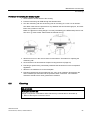
SITRANS P DS III
1
___________________
Introduction
2
___________________
Safety notes
SITRANS
Pressure transmitter
SITRANS P DS III
3
___________________
Description
4
___________________
Connecting
5
___________________
Maintenance and servicing
6
___________________
Technical specifications
Service Manual
Ordering data for spare
7
___________________
parts/accessories
A
___________________
Appendix
7MF4.33.. 7MF4.34.. 7MF4.35..
06/2014
A5E34219855-01
Legal information
Warning notice system
This manual contains notices you have to observe in order to ensure your personal safety, as well as to prevent
damage to property. The notices referring to your personal safety are highlighted in the manual by a safety alert
symbol, notices referring only to property damage have no safety alert symbol. These notices shown below are
graded according to the degree of danger.
DANGER
indicates that death or severe personal injury will result if proper precautions are not taken.
WARNING
indicates that death or severe personal injury may result if proper precautions are not taken.
CAUTION
indicates that minor personal injury can result if proper precautions are not taken.
NOTICE
indicates that property damage can result if proper precautions are not taken.
If more than one degree of danger is present, the warning notice representing the highest degree of danger will
be used. A notice warning of injury to persons with a safety alert symbol may also include a warning relating to
property damage.
Qualified Personnel
The product/system described in this documentation may be operated only by personnel qualified for the specific
task in accordance with the relevant documentation, in particular its warning notices and safety instructions.
Qualified personnel are those who, based on their training and experience, are capable of identifying risks and
avoiding potential hazards when working with these products/systems.
Proper use of Siemens products
Note the following:
WARNING
Siemens products may only be used for the applications described in the catalog and in the relevant technical
documentation. If products and components from other manufacturers are used, these must be recommended
or approved by Siemens. Proper transport, storage, installation, assembly, commissioning, operation and
maintenance are required to ensure that the products operate safely and without any problems. The permissible
ambient conditions must be complied with. The information in the relevant documentation must be observed.
Trademarks
All names identified by ® are registered trademarks of Siemens AG. The remaining trademarks in this publication
may be trademarks whose use by third parties for their own purposes could violate the rights of the owner.
Disclaimer of Liability
We have reviewed the contents of this publication to ensure consistency with the hardware and software
described. Since variance cannot be precluded entirely, we cannot guarantee full consistency. However, the
information in this publication is reviewed regularly and any necessary corrections are included in subsequent
editions.
Siemens AG
Industry Sector
Postfach 48 48
90026 NÜRNBERG
GERMANY
Order number: A5E34219855
Ⓟ 06/2014 Subject to change
Copyright © Siemens AG 2014.
All rights reserved
Table of contents
1
2
3
4
5
Introduction ............................................................................................................................................. 7
1.1
Purpose of this documentation ...................................................................................................... 7
1.2
Product information ........................................................................................................................ 7
1.3
History ............................................................................................................................................ 7
1.4
Checking the consignment ............................................................................................................. 8
1.5
Purpose .......................................................................................................................................... 8
1.6
Checking the compatibility of the application electronics .............................................................. 9
1.7
Transportation and storage ..........................................................................................................11
1.8
Notes on warranty ........................................................................................................................12
Safety notes .......................................................................................................................................... 15
2.1
2.1.1
2.1.2
Precondition for use .....................................................................................................................15
Laws and directives .....................................................................................................................15
Conformity with European directives ...........................................................................................15
2.2
Improper device modifications .....................................................................................................15
2.3
Use in hazardous areas ...............................................................................................................16
Description ............................................................................................................................................ 19
3.1
Structure .......................................................................................................................................19
3.2
Nameplate layout .........................................................................................................................20
3.3
Measuring point label layout ........................................................................................................21
Connecting ........................................................................................................................................... 23
4.1
Basic safety instructions ..............................................................................................................23
4.2
Connecting the device .................................................................................................................26
Maintenance and servicing .................................................................................................................... 29
5.1
Basic safety instructions ..............................................................................................................29
5.2
Defining the maintenance interval................................................................................................32
5.3
Checking the gaskets ...................................................................................................................33
5.4
Display in case of a fault ..............................................................................................................34
5.5
Changing the measuring cell and application electronics ............................................................34
5.6
User data following replacement..................................................................................................35
5.7
5.7.1
5.7.2
5.7.3
Replacing parts ............................................................................................................................40
Guarantee information .................................................................................................................40
Exploded view of the device ........................................................................................................40
Replacing the connection board ..................................................................................................41
SITRANS P DS III
Service Manual, 06/2014, A5E34219855-01
5
Table of contents
5.7.4
5.7.5
5.7.6
5.7.7
Replacing the pushbutton module .............................................................................................. 43
Replacing the display .................................................................................................................. 45
Replacing the application electronics .......................................................................................... 47
Replacing the measuring cell ...................................................................................................... 49
5.8
5.8.1
Cleaning ...................................................................................................................................... 51
Servicing the remote seal measuring system ............................................................................. 52
5.9
Return procedure ........................................................................................................................ 53
5.10
Disposal....................................................................................................................................... 54
6
Technical specifications ........................................................................................................................ 55
7
Ordering data for spare parts/accessories ............................................................................................. 57
A
Appendix .............................................................................................................................................. 65
A.1
Certificate .................................................................................................................................... 65
A.2
Technical support ........................................................................................................................ 65
A.3
Repair report for installation of spare parts ................................................................................. 67
Glossary ............................................................................................................................................... 69
Index .................................................................................................................................................... 73
SITRANS P DS III
6
Service Manual, 06/2014, A5E34219855-01
1
Introduction
1.1
Purpose of this documentation
These instructions contain all information that you will require to replace the application
electronics, measuring cell, and connection board of the device.
For information about the safe usage of the device, refer to the detailed version of these
instructions and corresponding safety instructions on the electronic data medium.
Read these instructions carefully before you start any service and maintenance work. In
order to use the device correctly, first make yourself acquainted with its principle of
operation.
Readership of these instructions are service and maintenance technicians.
1.2
Product information
The programming manual is an integral part of the CD, which is either supplied or can be
ordered. The programming manual is also available on the Siemens homepage.
On the CD, you will also find the catalog extract with the ordering data, the Software Device
Install for SIMATIC PDM for additional installation, and the required software.
See also
Product information on SITRANS P in the Internet (http://www.siemens.com/sitransp)
Catalog process instrumentation (http://www.siemens.com/processinstrumentation/catalogs)
1.3
History
This history establishes the correlation between the current documentation and the valid
firmware of the device.
The documentation of this edition applies to the following firmware:
Edition
Firmware identifier nameplate
System integration
Installation path for PDM
06/2014
HART:
FW: 11.03.03, FW: 11.03.04,
FW: 11.03.05, FW: 11.03.06
SIMATIC PDM 8.x and
previous versions
SITRANS P DSIII.2
PA: FW: 301.01.10
FF: FW: 11.01.01
SITRANS P DS III
Service Manual, 06/2014, A5E34219855-01
7
Introduction
1.4 Checking the consignment
1.4
Checking the consignment
1. Check the packaging and the spare parts for visible damage caused by inappropriate
handling during shipping.
2. Report any claims for damages immediately to the shipping company.
3. Retain the damaged parts for clarification.
4. Check the scope of delivery by comparing your order with the shipping documents for
correctness and completeness.
WARNING
Using damaged or incomplete spare parts
Danger of explosion in hazardous areas.
• Do not use damaged or incomplete spare parts.
1.5
Purpose
Overview
Depending on the version, a transmitter measures corrosive, non-corrosive and hazardous
gases, vapors and liquids.
You can use the transmitter for the following types of measurement:
● Gauge pressure
● Absolute pressure
● Differential pressure
With appropriate parameter settings and the necessary add-on parts (e.g. flow orifices and
remote seals), the pressure transmitter can also be used for the following measurements:
● Level
● Volume
● Mass
● Volume of flow
● Mass flow rate
The output signal is always a load-independent direct current between 4 and 20 mA.
You can install the "intrinsically-safe" or "explosion-proof" version of the transmitter in
hazardous areas. The devices have an EC type examination certificate and comply with the
appropriate harmonized European CENELEC directives.
Transmitters with remote seals of different shapes can be delivered for special applications.
For example, measuring high-viscosity substances is a special application.
SITRANS P DS III
8
Service Manual, 06/2014, A5E34219855-01
Introduction
1.6 Checking the compatibility of the application electronics
Operate the device in accordance with the "Technical specifications" chapter in the operating
instructions.
For additional information, refer to the operating instructions for the device.
1.6
Checking the compatibility of the application electronics
1. The table shown below indicates whether the new application electronics matches the
device.
2. Check the product version on the application electronics sticker.
3. Check the compatibility mark on the nameplate of the device.
Table 1- 1
The following table is valid for: SITRANS P DS III with HART (7MF4.33..)
Product version (ES)
Compatibility mark
Remark
007 to 025
K = 01
Replacement not possible
030 to 035
K = 01
Replacement possible
Table 1- 2
The following table is valid for:
SITRANS P DS III with PA (7MF4.34..) and SITRANS P DS III with FF (7MF4.35..)
Product version (ES)
Compatibility mark
Remark
001 to 015
K = 01
Replacement possible
SITRANS P DS III
Service Manual, 06/2014, A5E34219855-01
9
Introduction
1.6 Checking the compatibility of the application electronics
Example of application electronics for
SITRANS P DS III with PA and
FF
Product version (ES)
①
①
Example of application electronics for
SITRANS P DS III with HART
Compatibility mark
Figure 1-1
Compatibility mark on the nameplate
SITRANS P DS III
10
Service Manual, 06/2014, A5E34219855-01
Introduction
1.7 Transportation and storage
Figure 1-2
Example of incrementing of product version and compatibility mark and their possible
combinations for future developments
See also
Nameplate layout (Page 20)
1.7
Transportation and storage
To guarantee sufficient protection during transport and storage, observe the following:
● Keep the original packaging for subsequent transportation.
● Devices/replacement parts should be returned in their original packaging.
● If the original packaging is no longer available, please ensure that all shipments are
sufficiently protected during transport by the replacement packaging. Siemens accepts no
liability for additional costs resulting from damage in transit.
CAUTION
Insufficient protection during storage
The packaging only provides limited protection against moisture and infiltration.
• Provide additional packaging as necessary.
Information on special conditions for storage and transportation of the device and spare
parts can be found in the "Technical specifications" chapter in the operating instructions.
SITRANS P DS III
Service Manual, 06/2014, A5E34219855-01
11
Introduction
1.8 Notes on warranty
1.8
Notes on warranty
The contents of this manual shall not become part of or modify any prior or existing
agreement, commitment or legal relationship. The sales contract contains all obligations on
the part of Siemens as well as the complete and solely applicable warranty conditions. Any
statements regarding device versions described in the manual do not create new warranties
or modify the existing warranty.
The content reflects the technical status at the time of publishing. Siemens reserves the right
to make technical changes in the course of further development.
SITRANS P DS III
12
Service Manual, 06/2014, A5E34219855-01
Introduction
1.8 Notes on warranty
SITRANS P DS III
Service Manual, 06/2014, A5E34219855-01
13
2
Safety notes
2.1
Precondition for use
2.1.1
Laws and directives
Observe the test certification, provisions and laws applicable in your country during
connection, assembly and operation. These include, for example:
● National Electrical Code (NEC - NFPA 70) (USA)
● Canadian Electrical Code (CEC) (Canada)
Further provisions for hazardous area applications are for example:
● IEC 60079-14 (international)
● EN 60079-14 (EC)
2.1.2
Conformity with European directives
The device complies with the European directives even following the use of replacement
parts.
2.2
Improper device modifications
WARNING
Improper device modifications
Danger to personnel, system and environment can result from modifications to the device,
particularly in hazardous areas.
• Only carry out modifications that are described in the instructions for the device. Failure
to observe this requirement cancels the manufacturer's warranty and the product
approvals.
SITRANS P DS III
Service Manual, 06/2014, A5E34219855-01
15
Safety notes
2.3 Use in hazardous areas
2.3
Use in hazardous areas
Qualified personnel for hazardous area applications
Persons who install, connect, commission, operate, and service the device in a hazardous
area must have the following specific qualifications:
● They are authorized, trained or instructed in operating and maintaining devices and
systems according to the safety regulations for electrical circuits, high pressures,
aggressive, and hazardous media.
● They are authorized, trained, or instructed in carrying out work on electrical circuits for
hazardous systems.
● They are trained or instructed in maintenance and use of appropriate safety equipment
according to the pertinent safety regulations.
WARNING
Loss of the safety of the device with type of protection "Intrinsic safety Ex i"
If the device has already been operated in non-intrinsically safe circuits or the information
on the electrical specifications have been ignored, the safety of the device is no longer
ensured for use in hazardous areas. There is a danger of explosion.
• Connect the device in Intrinsic Safety type of protection solely to an intrinsically safe
circuit.
• Observe the information on the electrical specifications in the certificate and in the
"Technical specifications" chapter in the operating instructions.
WARNING
Use of incorrect device parts in potentially explosive environments
Devices and their associated device parts are either approved for different types of
protection or they do not have explosion protection. There is a danger of explosion if device
parts (such as covers) are used for devices with explosion protection that are not expressly
suited for this type of protection. If you do not adhere to these guidelines, the test
certificates and the manufacturer warranty will become null and void.
• Use only device parts that have been approved for the respective type of protection in
the potentially explosive environment. Covers that are not suited for the "explosionproof" type of protection are identified as such by a notice label attached to the inside of
the cover with "Not Ex d Not SIL".
• Do not swap device parts unless the manufacturer specifically ensures compatibility of
these parts.
SITRANS P DS III
16
Service Manual, 06/2014, A5E34219855-01
Safety notes
2.3 Use in hazardous areas
WARNING
Risk of explosion due to electrostatic charge
To prevent the build-up of an electrostatic charge in a hazardous area, the key cover must
be closed during operation and the screws tightened.
The key cover may be opened temporarily at any time for the purposes of operating the
pressure transmitter, even during plant operation; the screws should then be tightened
again.
SITRANS P DS III
Service Manual, 06/2014, A5E34219855-01
17
Safety notes
2.3 Use in hazardous areas
SITRANS P DS III
18
Service Manual, 06/2014, A5E34219855-01
3
Description
3.1
Structure
Depending on a customer-specific order, the device comprises different parts.
①
②
③
④
Key cover
⑤
Retaining screw; twist proofing of the measuring cell
in relation to the electronics enclosure
⑥
⑦
Cover (front), optionally with inspection window
Display (optional)
Measuring point label
Process connection
⑧
⑨
⑩
⑪
Cable inlet, optionally with cable gland
⑫
Nameplate (approval information)
⑬
Cover (rear) for electrical terminal compartment
Electrical terminal compartment
Protective conductor connector/equipotential
bonding terminal
Blanking plug
Nameplate (general information)
Figure 3-1
View of the transmitter: Left: Front right: Rear view
● The electronics enclosure is made of die cast aluminum or precision cast stainless steel.
● The housing has a removable circular cover at the front and the back.
● Depending on the device version, the front cover ② may be designed as an inspection
window. You can read the measured values straight off the digital display through this
inspection window.
● The cable inlet ⑧ to the electrical terminal compartment is at the side; either the left or
right-hand one can be used. The unused opening is closed with a blanking plug ⑬.
● The protective conductor terminal/equipotential bonding terminal ⑪ is located at the back
of the enclosure.
SITRANS P DS III
Service Manual, 06/2014, A5E34219855-01
19
Description
3.2 Nameplate layout
● The electrical terminal compartment ⑩ for the auxiliary power and shield is accessible
when you remove the back cover ⑨.
● The measuring cell with a process connection ⑥ is located in the lower section of the
enclosure. This measuring cell is secured against twisting by a retaining screw ⑤.
Thanks to the modular design of the transmitter, the measuring cell and application
electronics or connection board can be replaced if required.
● On the upper face of the enclosure you can see crosshead screws which secure the key
cover ①, under which there are 3 keys for local operation.
3.2
Nameplate layout
Nameplate with general information
The nameplate bearing the Order No. and other important information, such as design
details and technical data, is on the side of the enclosure.
①
Order number (machine-readable product
code)
Figure 3-2
②
Serial number
Example of a nameplate
SITRANS P DS III
20
Service Manual, 06/2014, A5E34219855-01
Description
3.3 Measuring point label layout
Nameplate with approval information
On the opposite side is the nameplate with approval information. This nameplate shows e.g.
the hardware and firmware versions. You must also observe the information in the relevant
certificate for a transmitter version for use in hazardous areas.
①
②
③
④
Characteristics for hazardous area
⑤
Maximum surface temperature
(temperature class)
Category for operating area
⑥
⑦
⑧
Device protection level
Type of protection
Group (gas, dust)
Figure 3-3
3.3
Firmware identifier
Hardware identifier
Example of a nameplate
Measuring point label layout
Figure 3-4
Example of measuring point label
SITRANS P DS III
Service Manual, 06/2014, A5E34219855-01
21
Description
3.3 Measuring point label layout
SITRANS P DS III
22
Service Manual, 06/2014, A5E34219855-01
4
Connecting
4.1
Basic safety instructions
WARNING
Unsuitable cables and/or cable glands
Danger of explosion in hazardous areas.
• Only use appropriate cables and cable glands complying with the requirements
specified in the "Technical specifications" chapter in the operating instructions.
• Tighten the cable glands in accordance with the torques specified in the "Technical
specifications" chapter in the operating instructions.
• When replacing cable glands, only use ones of the same type.
• After installation check that the cables are seated firmly.
WARNING
Hazardous contact voltage in versions with 4-conductor extension
Danger of electrocution in case of incorrect connection.
• Observe the instructions in the 4-conductor extension operating manual for the electrical
connection.
WARNING
Improper power supply
Danger of explosion in hazardous areas as result of incorrect power supply, e.g. using
direct current instead of alternating current.
• Connect the device in accordance with the specified power supply and signal circuits.
The relevant specifications can be found in the certificates, in the "Technical
specifications" chapter in the operating instructions, or on the nameplate.
WARNING
Unsafe extra-low voltage
Danger of explosion in hazardous areas due to voltage flashover.
• Connect the device to an extra-low voltage with safe isolation (SELV).
SITRANS P DS III
Service Manual, 06/2014, A5E34219855-01
23
Connecting
4.1 Basic safety instructions
WARNING
Lack of equipotential bonding
Danger of explosion through compensating currents or ignition currents through lack of
equipotential bonding.
• Ensure that the device is potentially equalized.
Exception: It may be permissible to omit connection of the equipotential bonding for devices
with type of protection "Intrinsic safety Ex i".
WARNING
Unprotected cable ends
Danger of explosion through unprotected cable ends in hazardous areas.
• Protect unused cable ends in accordance with IEC/EN 60079-14.
WARNING
Improper laying of shielded cables
Danger of explosion through compensating currents between hazardous area and the nonhazardous area.
• Only ground shielded cables that run into the hazardous area at one end.
• If grounding is required at both ends, use an equipotential bonding conductor.
WARNING
Connecting device in energized state
Danger of explosion in hazardous areas.
• Connect devices in hazardous areas only in a de-energized state.
Exceptions:
• Circuits of limited energy may also be connected in the energized state in hazardous
areas.
• Exceptions for type of protection "Non-sparking nA" (Zone 2) are regulated in the
relevant certificate
SITRANS P DS III
24
Service Manual, 06/2014, A5E34219855-01
Connecting
4.1 Basic safety instructions
WARNING
Incorrect selection of type of protection
Danger of explosion in areas subject to explosion hazard.
This device is approved for several types of protection.
1. Decide in favor of one type of protection.
2. Connect the device in accordance with the selected type of protection.
3. In order to avoid incorrect use at a later point, make the types of protection that are not
used permanently unrecognizable on the nameplate.
NOTICE
Ambient temperature too high
Damage to cable sheath.
• At an ambient temperature ≥ 60 °C (140 °F), use heat-resistant cables suitable for an
ambient temperature at least 20 °C (68 °F) higher.
NOTICE
Incorrect measured values with incorrect grounding
The device must not be grounded via the "+" connection. It may otherwise malfunction and
be permanently damaged.
• If necessary, ground the device using the "-" connection.
Note
Electromagnetic compatibility (EMC)
You can use this device in industrial environments, households and small businesses.
For metal housings there is an increased electromagnetic compatibility compared to highfrequency radiation. This protection can be increased by grounding the housing, see Chapter
"Connecting the device (Page 26)".
SITRANS P DS III
Service Manual, 06/2014, A5E34219855-01
25
Connecting
4.2 Connecting the device
Note
Improvement of interference immunity
• Lay signal cables separate from cables with voltages > 60 V.
• Use cables with twisted wires.
• Keep the device and the cables at a distance from strong electromagnetic fields.
• Use shielded cables to guarantee the full specification according to HART.
• Refer to the information on HART communication in the "Technical specifications"
chapter in the operating instructions.
4.2
Connecting the device
Opening the device
1. Unscrew the cover of the electrical cable compartment. An identification text "FIELD
TERMINALS" is provided at the side of the housing.
Connecting the device
1. Lead the connecting cable through the cable gland ③.
2. Connect the device to the plant with the protective conductor connection ⑦.
3. Connect the wires to the connecting terminals ④ "+" and "-".
Ensure the correct polarity! If necessary, ground the device using the "-" connection by
connecting the "-" connection to the ground terminal ⑨.
4. If necessary, connect the shield to the screw of the ground terminal ⑨. This is electrically
connected with the external protective conductor connection.
SITRANS P DS III
26
Service Manual, 06/2014, A5E34219855-01
Connecting
4.2 Connecting the device
HART
PROFIBUS PA / Foundation™ Fieldbus FF
①
②
Feed separator with integrated load
⑥
⑦
Safety catch
③
Cable entry for auxiliary power/analog
output
⑧
Process connection
④
⑤
Connecting terminals
⑨
⑩
Ground terminal
Auxiliary power
Test connector for direct current
measuring device or connection for
external display
Protective conductor connection/
equipotential bonding terminal
PROFIBUS PA / Foundation™ Fieldbus
FF
Electrical connection, power supply
SITRANS P DS III
Service Manual, 06/2014, A5E34219855-01
27
Connecting
4.2 Connecting the device
Closing the device
1. Screw the covers ④⑦ back on as far as they will go.
2. Secure each cover with the cover catch ③⑥.
3. Close the key cover ①.
4. Tighten the screws in the key cover.
5. Check the tightness of the blanking plugs ⑤ and cable gland ② in accordance with the
degree of protection.
①
②
③
④
Key cover
Cable gland
Safety catch (back)
Cover (rear) for electrical terminal compartment
Figure 4-1
⑤
⑥
⑦
⑧
Blanking plug
Safety catch (front)
Cover (front), optionally with inspection window
Safety catch for stainless steel enclosure
View of the transmitter: Left: Back right: Front view
SITRANS P DS III
28
Service Manual, 06/2014, A5E34219855-01
Maintenance and servicing
5.1
5
Basic safety instructions
WARNING
Impermissible repair of explosion protected devices
Danger of explosion in areas subject to explosion hazard.
• Repair must be carried out by Siemens authorized personnel only.
WARNING
Impermissible accessories and spare parts
Danger of explosion in areas subject to explosion hazard.
• Only use original accessories or original spare parts.
• Observe all relevant installation and safety instructions described in the instructions for
the device or enclosed with the accessory or spare part.
WARNING
Use of incorrect device parts in potentially explosive environments
Devices and their associated device parts are either approved for different types of
protection or they do not have explosion protection. There is a danger of explosion if device
parts (such as covers) are used for devices with explosion protection that are not expressly
suited for this type of protection. If you do not adhere to these guidelines, the test
certificates and the manufacturer warranty will become null and void.
• Use only device parts that have been approved for the respective type of protection in
the potentially explosive environment. Covers that are not suited for the "explosionproof" type of protection are identified as such by a notice label attached to the inside of
the cover with "Not Ex d Not SIL".
• Do not swap device parts unless the manufacturer specifically ensures compatibility of
these parts.
SITRANS P DS III
Service Manual, 06/2014, A5E34219855-01
29
Maintenance and servicing
5.1 Basic safety instructions
WARNING
Maintenance during continued operation in a hazardous area
There is a danger of explosion when carrying out repairs and maintenance on the device in
a hazardous area.
• Isolate the device from power.
- or • Ensure that the atmosphere is explosion-free (hot work permit).
WARNING
Commissioning and operation with pending error
If an error message appears, correct operation in the process is no longer guaranteed.
• Check the gravity of the error.
• Correct the error.
• If the error still exists:
– Take the device out of operation.
– Prevent renewed commissioning.
WARNING
Hot, toxic or corrosive process media
Danger of injury during maintenance work.
When working on the process connection, hot, toxic or corrosive process media could be
released.
• As long as the device is under pressure, do not loosen process connections and do not
remove any parts that are pressurized.
• Before opening or removing the device ensure that process media cannot be released.
WARNING
Improper connection after maintenance
Danger of explosion in areas subject to explosion hazard.
• Connect the device correctly after maintenance.
• Close the device after maintenance work.
Refer to Chapter "Connecting the device (Page 26)".
SITRANS P DS III
30
Service Manual, 06/2014, A5E34219855-01
Maintenance and servicing
5.1 Basic safety instructions
WARNING
Use of a computer in a hazardous area
If the interface to the computer is used in the hazardous area, there is a danger of
explosion.
• Ensure that the atmosphere is explosion-free (hot work permit).
CAUTION
Releasing key lock
Improper modification of parameters could influence process safety.
• Make sure that only authorized personnel may cancel the key locking of devices for
safety-related applications.
CAUTION
Hot surfaces
Danger of burns during maintenance work on parts having surface temperatures exceeding
70 °C (158 °F).
• Take corresponding protective measures, for example by wearing protective gloves.
• After carrying out maintenance, remount touch protection measures.
WARNING
Hazardous voltage with open device in versions with 4-conductor extension
Danger of electrocution when the enclosure is opened or enclosure parts are removed.
• Disconnect the device before you open the enclosure or remove enclosure parts.
• Observe the special precautionary measures if maintenance is required while the device
is live. Have maintenance work carried out by qualified personnel.
SITRANS P DS III
Service Manual, 06/2014, A5E34219855-01
31
Maintenance and servicing
5.2 Defining the maintenance interval
NOTICE
Electrostatic-sensitive devices
The device contains electrostatic-sensitive devices (ESD). ESD can be destroyed by
voltages far too low to be detected by humans. These voltages can occur if you simply
touch a component part or the electrical connections of a module without being
electrostatically discharged. The damage to a module caused by overvoltage cannot
normally be detected immediately; it only becomes apparent after a longer period of
operating time has elapsed.
Protective measures against the discharge of static electricity:
• Make sure that no power is applied.
• Before working with modules, make sure that you discharge static from your body, for
example by touching a grounded object.
• Devices and tools used must be free of static charge.
• Hold modules only by their edges.
• Do not touch connector pins or conductor tracks on a module with the ESD notice.
5.2
Defining the maintenance interval
WARNING
No maintenance interval has been defined
Device failure, device damage, and risk of injury.
• Define a maintenance interval for regular tests in line with device use and empirical
values.
• The maintenance interval will vary from site to site depending on corrosion resistance.
SITRANS P DS III
32
Service Manual, 06/2014, A5E34219855-01
Maintenance and servicing
5.3 Checking the gaskets
5.3
Checking the gaskets
Inspect the seals at regular intervals
Note
Incorrect seal changes
Incorrect measured values will be displayed. Changing the seals in a process flange of a
differential pressure measuring cell can alter the start-of-scale value.
• Changing seals in devices with differential pressure measuring cells may only be carried
out by personnel authorized by Siemens.
Note
Using the wrong seals
Using the wrong seals with flush-mounted process connections can cause measuring errors
and/or damage the diaphragm.
• Always use seals which comply with the process connection standards or are
recommended by Siemens.
1. Clean the enclosure and seals.
2. Check the enclosure and seals for cracks and damage.
3. Grease the seals if necessary.
- or 4. Replace the seals.
SITRANS P DS III
Service Manual, 06/2014, A5E34219855-01
33
Maintenance and servicing
5.4 Display in case of a fault
5.4
Display in case of a fault
Check the start of scale value of the device from time to time.
Differentiate between the following in case of a fault:
● The internal self test has detected a fault, e.g. sensor break, hardware fault/Firmware
fault.
Displays:
– Display: "ERROR" display and ticker with an error text
– Analog output: Factory setting: Failure current 3.6 or 22.8 mA
Or depending on the parameterization
– HART: detailed error breakdown for display in the HART communicator or SIMATIC
PDM
● Grave hardware faults, the processor is not functioning.
Displays:
– Display: no defined display
– Analog output: failure current < 3.6 mA
In the event of a defect, you can replace the application electronics by following the warning
notes and the provided operating instructions.
5.5
Changing the measuring cell and application electronics
Related
Each of the individual components "Measuring cell" and "Electronics" has a non-volatile
memory (EEPROM).
Measuring cell data (e.g.: measuring range, measuring cell material, oil filling) and user data
of the application electronics (e.g.: downscaling, additional electrical damping) are located in
the measuring cell EEPROM. User data is lost when the measuring cell is replaced.
Application-specific data are not lost when the application electronics are changed.
You can backup user data before changing the measuring cell and reload it afterwards. Use
an input device which supports the HART protocol. (e.g. HART communicator, PC with
HART modem and HART software or PC with HART modem and PDM software). Factory
settings will be used if user data is not backed up before the measuring cell is changed.
Technical developments enable advanced functions to be implemented in the firmware of the
measuring cell or application electronics. Further technical developments are indicated by
modified firmware statuses (FW). The firmware status does not affect whether the modules
can be replaced. However, the scope of functions is limited to the function of existing
components.
If a combination of certain firmware versions of measuring cell and application electronics is
not possible for technical reasons, the device will identify this problem and go into "Fault
current" mode. This information is provided via the HART interface.
SITRANS P DS III
34
Service Manual, 06/2014, A5E34219855-01
Maintenance and servicing
5.6 User data following replacement
5.6
User data following replacement
This chapter describes which user data is reset to the factory setting following replacement
of the application electronics or measuring cell.
The following tables are identified as follows:
*: The parameter names identified by * can be found in SIMATIC PDM under the menu items
"Device" or "View".
①: The user data identified by ① is reset to the factory setting following replacement of the
measuring cell.
②: The user data identified by ② is reset to the factory setting following replacement of the
application electronics.
Table 5- 1
SITRANS P DS III with HART
Parameter name in SIMATIC PDM
Status of user data following
replacement of application
electronics or measuring cell
Value following resetting to factory
setting
Operating unit / TAG
①
-
Device / sensor serial number
①
-
Unit and cycle time / unit
①
bar
Unit and cycle time / cycle time
①
90 ms
Measuring limits / min. measuring range
①
-
Measuring limits / min. start-of-scale value,
max. full-scale value
①
-
Measured-value scaling, start-of-scale value
①
0.0
Measured-value scaling, full-scale value
①
Upper sensor limit
Analog output limits / lower/upper limit
①
3.8 / 20.5 mA
Alarm status / analog output alarm type
①
Lower
Alarm status / lower/upper alarm value
①
3.6 / 22.8 mA
Damping
①
0.1 s
Characteristic / transfer function
①
Linear
Characteristic / start of root extraction
①
5%
Display and user interface / tracking unit
①
mA
Design (all material data)
①
-
Sensor calibration / upper/lower calibration
point
①
Like factory-set sensor limits, without
transformation
Sensor calibration / lower calibration point
①
0.0
Sensor calibration / upper calibration point
①
Upper sensor limit
Service interval for sensor (all settings)
①
-
SITRANS P DS III
Service Manual, 06/2014, A5E34219855-01
35
Maintenance and servicing
5.6 User data following replacement
Parameter name in SIMATIC PDM
Status of user data following
replacement of application
electronics or measuring cell
Value following resetting to factory
setting
Certificates and approvals / explosion
protection
①
-
* Polling address
①
-
* Min/max pointers for pressure / sensor
temperature
①
-
* Sensor calibration / zero calibration
①
-
* Sensor calibration / upper/lower calibration
①
-
* Position error calibration
①
0.0
* Operating hours counter, sensor
①
-
Operating unit / message
②
-
Operating unit / description
②
-
Device / software revision
②
-
Device / hardware revision
②
-
Device / field device revision
②
-
Device / date
②
-
Device / factory number
②
-
Display and user interface / local display unit
②
-
Display and user interface / bargraph
②
-
Display and user interface / local operation
②
-
Calibration interval for application electronics
(all settings)
②
-
Current saturation monitoring / alarm activation
②
-
Current saturation monitoring / saturation
alarm, alarm duration
②
-
* Operating hours counter, application
electronics
②
-
* Analog output D/A calibration (customerspecific)
②
Like factory-set D/A calibration
* Min/max pointers for application electronics
temperature
②
-
Table 5- 2
SITRANS P DS III with PA
Parameter name in SIMATIC PDM
Status of user data following replacement of application electronics or
measuring cell
Identification / device / sensor type
①
Identification / device / sensor serial number
①
SITRANS P DS III
36
Service Manual, 06/2014, A5E34219855-01
Maintenance and servicing
5.6 User data following replacement
Parameter name in SIMATIC PDM
Status of user data following replacement of application electronics or
measuring cell
Input / transducer block 1 / measuring limits /
min. start-of-scale value
①
Input / transducer block 1 / measuring limits /
max. full-scale value
①
Conditions of use / process conditions / max.
media pressure limit
①
Diagnostics settings / service interval for
sensor (all settings)
①
Design / type / measuring cell / measuring cell
filling
①
Design / type / measuring cell / seal diaphragm
material
①
Design / type / measuring cell / O-ring material
①
Design / type / remote seal / number of remote
seal flanges
①
Design / type / remote seal / remote seal type
①
Design / type / remote seal / diaphragm
material
①
Design / type / remote seal / remote seal filling
①
Design / type / remote seal / tube length
①
Design / type / process connection / process
connection type
①
Design / type / process connection / venting
valve material
①
Design / type / process connection / venting
valve position
①
Design / type / process connection / process
flange screws
①
Design / type / process connection / flange
type
①
Design / type / process connection / flange
material
①
Design / electrical connection / electronics
housing material
①
Design / electrical connection / electrical
connection
①
Certificates and approvals / explosion
protection
①
* Operating hours counter, sensor
①
* Min/max pointers for pressure / sensor
temperature
①
Identification / operating unit / TAG
②
Identification / operating unit / description
②
SITRANS P DS III
Service Manual, 06/2014, A5E34219855-01
37
Maintenance and servicing
5.6 User data following replacement
Parameter name in SIMATIC PDM
Status of user data following replacement of application electronics or
measuring cell
Identification / operating unit / message
②
Identification / device / device serial number
②
Identification / device / software revision
②
Identification / device / hardware revision
②
Identification / device / PROFIBUS Ident
Number
②
Identification / device / installation date
②
Identification / device / Order No.
②
Input / transducer block 1 / transducer type
②
Input / transducer block 1 / measuring limits /
pressure unit, raw value
②
Input / transducer block 1 / measuring range /
unit (secondary variable 1)
②
Input / transducer block 1 / measuring range /
start-of-scale value
②
Input / transducer block 1 / measuring range /
full-scale value
②
Input / transducer block 1 / working range /
unit
②
Input / transducer block 1 / working range /
start-of-scale value
②
Input / transducer block 1 / working range /
full-scale value
②
Input / transducer block 1 / characteristic /
low-flow cut-off
②
Input / transducer block 1 / characteristic /
start of root function
②
Input / transducer block 1 / interpolation points
(all settings)
②
Input / transducer block 1 / sensor
temperature / temperature unit
②
Output / Function Block 1 - analog input (all
settings)
②
Output / Function Block 2 - totalizer (all
settings)
②
Display and user interface / local operation
②
Display and user interface / source for display
②
Display and user interface / decimal places in
display
②
Diagnostics settings / enabling of diagnostics
②
Diagnostics settings / calibration interval for
application electronics (all settings)
②
SITRANS P DS III
38
Service Manual, 06/2014, A5E34219855-01
Maintenance and servicing
5.6 User data following replacement
Parameter name in SIMATIC PDM
Status of user data following replacement of application electronics or
measuring cell
* Sensor calibration
②
* Position error calibration
②
* Write block
②
* Operating hours counter, application
electronics
②
* Min/max pointers for electronics temperature
②
SITRANS P DS III
Service Manual, 06/2014, A5E34219855-01
39
Maintenance and servicing
5.7 Replacing parts
5.7
Replacing parts
5.7.1
Guarantee information
Following replacement of a part, a guarantee is only valid for the individual components and
not for the complete device.
5.7.2
Exploded view of the device
Depending on a customer-specific order, the device comprises different parts. The next
chapters show you how to replace the components.
1
Cover (front), optionally with inspection
window
8
Cover (rear) for electronic terminal
compartment
2
O-ring between the cover and housing
9
Connection for digital display
3
Display (optional)
10
Measuring cell
4
Threaded bolts
11
Connection board
5
Application electronics
12
Keyboard PCB
6
Measuring cell PCB
13
Mounting screws
7
Housing
Figure 5-1
Exploded view of the transmitter
SITRANS P DS III
40
Service Manual, 06/2014, A5E34219855-01
Maintenance and servicing
5.7 Replacing parts
5.7.3
Replacing the connection board
Procedure for replacing the connection board
1. Isolate the device from power.
2. Use a 3 mm Allen key to loosen the cover.
3. Open the cover (rear) of the electronic connection compartment.
4. Disconnect the cables from the connection board.
5. On the left and right side, remove the recessed-head screws that hold the connection
board to the enclosure.
SITRANS P DS III
Service Manual, 06/2014, A5E34219855-01
41
Maintenance and servicing
5.7 Replacing parts
6. Make sure when loosening the recessed-head screws that the washers (serrated
washers) are not lost.
7. Remove the connection board.
SITRANS P DS III
42
Service Manual, 06/2014, A5E34219855-01
Maintenance and servicing
5.7 Replacing parts
To install the connection board, proceed as follows
1. Insert the new connection board so that its contact pins on rear side mate the contacts in
the housing.
2. Work in the reverse order as described in "Procedure for replacing the connection board".
3. Close the device as described in Chapter Closing the device (Page 26).
5.7.4
Replacing the pushbutton module
1. Isolate the device from power.
2. In order to open the pushbutton flap, loosen the two recessed-head screws on the
outside.
SITRANS P DS III
Service Manual, 06/2014, A5E34219855-01
43
Maintenance and servicing
5.7 Replacing parts
3. Remove the two splints on the pushbutton flap using flat-nose pliers.
4. Remove the pushbutton flap.
5. Use a TX10 Torx screwdriver or Phillips screwdriver to loosen the two screws of the
pushbutton insert you can now see.
6. Remove the pushbutton insert from the housing.
7. Remove the three keys with springs from the pushbutton insert.
Procedure for installing the pushbutton module
1. Work in the reverse order as described in "Procedure for replacing the pushbutton
module".
2. When inserting the new pushbutton module, make sure that the magnets of the keys
point to the front in the direction of the display.
SITRANS P DS III
44
Service Manual, 06/2014, A5E34219855-01
Maintenance and servicing
5.7 Replacing parts
5.7.5
Replacing the display
Procedure for replacing the display
1. Open the front cover (optional with inspection window).
2. Remove the recessed-head screws on the left and right on the display.
SITRANS P DS III
Service Manual, 06/2014, A5E34219855-01
45
Maintenance and servicing
5.7 Replacing parts
3. Pull the display out of the housing.
4. Remove the connector of the ribbon cable from the application electronics.
Procedure for installing the display
1. You can also turn the mounting position of the display by 90 ° or 180 °.
2. Work in the reverse order as described in "Procedure for replacing the display".
3. Close the device as described in Chapter Closing the device (Page 26).
SITRANS P DS III
46
Service Manual, 06/2014, A5E34219855-01
Maintenance and servicing
5.7 Replacing parts
5.7.6
Replacing the application electronics
Procedure for replacing the application electronics
1. Isolate the device from power.
2. Remove the display. Compare section Replacing the display (Page 45).
3. Use a 7 mm socket wrench to remove the hexagon stud bolts on the left and right.
4. Remove the application electronics.
5. Remove the measuring cell PCB from the application electronics. To do this, carefully
release the clip using a screwdriver as shown in the following picture.
SITRANS P DS III
Service Manual, 06/2014, A5E34219855-01
47
Maintenance and servicing
5.7 Replacing parts
6. Use a TX9 Torx screwdriver or Phillips screwdriver to unscrew the two screws of the
keyboard PCB you can now see from the base of the housing.
7. Remove the keyboard PCB.
Procedure for installing the application electronics
NOTICE
Frequent insertion of the measuring cell PCB
Device damage.
• Avoid frequent insertion of the measuring cell PCB.
1. Work in the reverse order as described in "Procedure for replacing the application
electronics".
2. When inserting the new application electronics, make sure that the contact pins fit in the
rear of the application electronics.
The ribbon cable of the measuring cell should be positioned between the contact pins,
and that of the keyboard PCB on the left of the pins.
3. Do not kink, pinch, tension or twist the ribbon cable when plugging it onto the application
electronics.
4. Close the device as described in Chapter Closing the device (Page 26).
5. Following a replacement, permanently obliterate the firmware ID on the nameplate if
applicable.
6. Write the new firmware ID on the nameplate.
7. Calibrate the zero point of the device, and also the span if necessary. Calibration of the
span is necessary if the device was matched e.g. to a control system prior to replacement
of the application electronics. Compare section Technical specifications (Page 55).
SITRANS P DS III
48
Service Manual, 06/2014, A5E34219855-01
Maintenance and servicing
5.7 Replacing parts
5.7.7
Replacing the measuring cell
Procedure for replacing the measuring cell
Note
When using the differential pressure cell, replace the complete measuring cell with process
flanges.
1. Isolate the device from power.
2. Remove the display. Compare section Replacing the display (Page 45).
3. Remove the application electronics. Compare section Replacing the application
electronics (Page 47).
SITRANS P DS III
Service Manual, 06/2014, A5E34219855-01
49
Maintenance and servicing
5.7 Replacing parts
4. Use a 2.5 mm Allen key to loosen the locking screw for fixing the measuring cell.
NOTICE
Damage to the ribbon cable
To avoid damage to the ribbon cable when installing or removing the measuring cell, do
not kink, pinch, tension or twist it.
• Do not kink, pinch, tension or twist the ribbon cable.
5. Turn the measuring cell counter-clockwise to remove it from the housing. To do this, use
a matching open-end wrench (relative pressure transmitter) or rotate the measuring cell
by hand.
SITRANS P DS III
50
Service Manual, 06/2014, A5E34219855-01
Maintenance and servicing
5.8 Cleaning
Procedure for installing the measuring cell
1. Clean residues off the thread of the housing.
2. Push the measuring cell PCB through the threaded hole.
3. Turn the measuring cell into the housing until an overhang of 2.6 mm ± 0.75 remains.
The ribbon cable must be present as a loop between the two feed-through pins, and must
follow every rotation of the cell.
Make sure that the mounting flange is correctly orientated on the differential pressure cell.
The arrow ② must remain visible within the marked area ①.
4. Work from here on in the reverse order as described in "Procedure for replacing the
measuring cell".
5. Close the device as described in Chapter Closing the device (Page 26).
6. Following a replacement, permanently obliterate the hardware ID on the nameplate if
applicable.
7. Write the new hardware ID on the nameplate.
8. Following replacement of the measuring cell, carry out an insulation test between the
short-circuited input terminals and the protective earth connection. The insulation
resistance should have a value greater than 10 MOhm.
5.8
Cleaning
WARNING
Dust layers above 5 mm
Danger of explosion in hazardous areas. Device may overheat due to dust build up.
• Remove dust layers in excess of 5 mm.
SITRANS P DS III
Service Manual, 06/2014, A5E34219855-01
51
Maintenance and servicing
5.8 Cleaning
NOTICE
Penetration of moisture into the device
Device damage.
• Make sure when carrying out cleaning and maintenance work that no moisture
penetrates the inside of the device.
Cleaning the enclosure
● Clean the outside of the enclosure and the display window using a cloth moistened with
water or a mild detergent.
● Do not use aggressive cleaning agents or solvents. Plastic components or painted
surfaces could be damaged.
WARNING
Electrostatic charge
Danger of explosion in hazardous areas if electrostatic charges develop, for example, when
cleaning plastic enclosures with a dry cloth.
• Prevent electrostatic charging in hazardous areas.
5.8.1
Servicing the remote seal measuring system
The remote seal measuring system usually does not need servicing.
If the mediums are contaminated, viscous or crystallized, it could be necessary to clean the
diaphragm from time to time. Use only a suitable solvent to remove the deposits from the
diaphragm. Do not use corrosive cleaning agents. Prevent the diaphragm from getting
damaged due to sharp-edged tools.
NOTICE
Improper cleaning of diaphragm
Device damage. The diaphragm can be damaged.
• Do not use sharp or hard objects to clean the diaphragm.
SITRANS P DS III
52
Service Manual, 06/2014, A5E34219855-01
Maintenance and servicing
5.9 Return procedure
5.9
Return procedure
Enclose the bill of lading, return document and decontamination certificate in a clear plastic
pouch and attach it firmly to the outside of the packaging.
Required forms
● Delivery note
● Return goods delivery note
(http://www.siemens.com/processinstrumentation/returngoodsnote)
with the following information:
– Product (item description)
– Number of returned devices/replacement parts
– Reason for returning the item(s)
● Decontamination declaration (http://www.siemens.com/sc/declarationofdecontamination)
With this declaration you warrant "that the device/replacement part has been carefully
cleaned and is free of residues. The device/replacement part does not pose a hazard for
humans and the environment."
If the returned device/replacement part has come into contact with poisonous, corrosive,
flammable or water-contaminating substances, you must thoroughly clean and
decontaminate the device/replacement part before returning it in order to ensure that all
hollow areas are free from hazardous substances. Check the item after it has been
cleaned.
Any devices/replacement parts returned without a decontamination declaration will be
cleaned at your expense before further processing.
The forms can be found on the Internet as well as in the documentation which comes with
the device.
SITRANS P DS III
Service Manual, 06/2014, A5E34219855-01
53
Maintenance and servicing
5.10 Disposal
5.10
Disposal
Devices identified by this symbol may not be disposed of in the
municipal waste disposal services under observance of the
Directive 2002/96/EC on waste electronic and electrical
equipment (WEEE).
They can be returned to the supplier within the EC or to a
locally approved disposal service. Observe the specific
regulations valid in your country.
Note
Special disposal required
The device includes components that require special disposal.
• Dispose of the device properly and environmentally through a local waste disposal
contractor.
SITRANS P DS III
54
Service Manual, 06/2014, A5E34219855-01
6
Technical specifications
This chapter describes the deviations from the technical specifications in the operating
instructions.
Deviations exist as follows in the measuring accuracy following replacement of the
application electronics or measuring cell:
Table 6- 1
Technical specifications > measuring accuracy
SITRANS P DS III with HART
No calibration of zero and span
Calibration of zero and span
Value doubled
Value remains unchanged
Value doubled
Value doubled
Measurement deviation with
limit setting, including hysteresis
and repeatability
Linear characteristic curve
•
r ≤ 10
Effect of ambient temperature
•
At -10 … +60 °C (14 … 140
°F)
r = maximum measuring span/set measuring span
SITRANS P DS III
Service Manual, 06/2014, A5E34219855-01
55
Technical specifications
SITRANS P DS III
56
Service Manual, 06/2014, A5E34219855-01
Ordering data for spare parts/accessories
7
SITRANS P DS III
Service Manual, 06/2014, A5E34219855-01
57
Ordering data for spare parts/accessories
SITRANS P DS III
58
Service Manual, 06/2014, A5E34219855-01
Ordering data for spare parts/accessories
SITRANS P DS III
Service Manual, 06/2014, A5E34219855-01
59
Ordering data for spare parts/accessories
SITRANS P DS III
60
Service Manual, 06/2014, A5E34219855-01
Ordering data for spare parts/accessories
SITRANS P DS III
Service Manual, 06/2014, A5E34219855-01
61
Ordering data for spare parts/accessories
See also
Process instrumentation catalog (http://www.siemens.com/processinstrumentation/catalogs)
SITRANS P DS III
62
Service Manual, 06/2014, A5E34219855-01
Ordering data for spare parts/accessories
SITRANS P DS III
Service Manual, 06/2014, A5E34219855-01
63
A
Appendix
A.1
Certificate
The certificates can be found on the enclosed CD and on the Internet under:
Certificates (http://www.siemens.com/processinstrumentation/certificates)
A.2
Technical support
Technical Support
You can contact Technical Support for all IA and DT products:
● Via the Internet using the Support Request:
Support request (http://www.siemens.com/automation/support-request)
● E-mail (mailto:[email protected])
● Phone: +49 (0) 911 895 7 222
● Fax: +49 (0) 911 895 7 223
Further information about our technical support is available on the Internet at
Technical Support (http://www.siemens.com/automation/csi/service)
Industry Online Support
In addition to our documentation, we offer a comprehensive knowledge base on the Internet
at:
Services & Support (http://www.siemens.com/automation/service&support)
There you will find:
● The latest product information, FAQs, downloads, tips and tricks.
● Our newsletter with the latest information about our products.
● A Knowledge Manager to find the right documents for you.
● Our bulletin board, where users and specialists share their knowledge worldwide.
● Your local contact partner for Industry Automation and Drives Technologies in our partner
database.
● Information about field service, repairs, spare parts and lots more under "Services."
SITRANS P DS III
Service Manual, 06/2014, A5E34219855-01
65
Appendix
A.2 Technical support
Additional Support
Please contact your local Siemens representative and offices if you have any questions
about the products described in this manual and do not find the right answers.
Find your contact partner at:
Partner (http://www.automation.siemens.com/partner)
Documentation for various products and systems is available at:
Instructions and manuals (http://www.siemens.com/processinstrumentation/documentation)
See also
Product information on SITRANS P in the Internet (http://www.siemens.com/sitransp)
Process instrumentation catalog (http://www.siemens.com/processinstrumentation/catalogs)
SITRANS P DS III
66
Service Manual, 06/2014, A5E34219855-01
Appendix
A.3 Repair report for installation of spare parts
A.3
Repair report for installation of spare parts
For your local documentation
Check mark the relevant items and fill out the fields
1. Customer information:
Company:
Address:
Department:
Tel / Fax:
E-mail:
System part:
2. Information on the original device: first replacement of a component ⃞
Electronic serial number:
Sensor serial number:
F-no.: (rating plate)
HW: Approval plate)
FW: (approval plate)
Device order no.:
7MF4 _ _ _ _ - _ _ _ _ _ - _ _ _ _ - Z _ _ _
Additional components
-Z___-Z___-Z___-Z___-Z___-Z___-Z___-Z___-Z___-Z___
3a. Device information Spare Part(1): Measuring cell
Sensor serial number:
Spare part order no.:
7MF499 _ - _ _ _ _ _ _ - Z _ _ _
Additional components
-Z___-Z___-Z___-Z___-Z___-Z___-Z___-Z___-Z___-Z___
3b. Device information Spare Part(2): Application electronics
Electronic serial number:
ES: (electronic cup)
FW: (electronic cup)
Spare part order no.:
7MF4999 - _ _ _ _ _ - _ _ _ _
3c. Device information Spare Part(3): Connection board
HW: (connection board)
Spare part order no.:
7MF4999 - _ _ _ _ _ - _ _ _ _
3d. Device information Spare Part(4): Pushbutton module
HW: (connection board)
Spare part order no.:
7MF4999 - _ _ _ _ _ - _ _ _ _
3e. Device information Spare Part(5): Display
HW: (connection board)
Spare part order no.:
7MF4999 - _ _ _ _ _ - _ _ _ _
3f. Device information Spare Part(6): Additional spare parts
HW: (connection board)
Spare part order no.:
7MF4999 - _ _ _ _ _ - _ _ _ _
4. Additional information
Installation location (precise
definition)
SITRANS P DS III
Service Manual, 06/2014, A5E34219855-01
67
Appendix
A.3 Repair report for installation of spare parts
For your local documentation
Repair period:
From:
To:
Safety measures:
Work completed:
5. Approval
Check mark the relevant
items and fill out the fields
Replacement documentation
was read and observed: ⃞
ESD guidelines were
observed: ⃞
Inspected by Ex expert: ⃞
Function test completed: ⃞
Name of Ex expert:
Date:
Signature of Ex expert:
Author name:
Date:
Author signature:
SITRANS P DS III
68
Service Manual, 06/2014, A5E34219855-01
Glossary
ATEX
ATEX is an abbreviation of the French term "Atmosphère explosible" (potentially explosive
atmosphere). ATEX stands for both EC directives in the area of explosion protection: ATEX
product directive 94/9/EC and ATEX operating directive 1999/92/EC.
Auxiliary power supply
Auxiliary power supply refers to an electrical supply or reference voltage which some
electrical circuits require apart from the standard supply. The auxiliary power supply can, for
example, be specially stabilized, have a particular level or polarity and/or other properties
which are important for the correct functioning of switch components.
Auxiliary voltage
→ Auxiliary power supply
Dangerous failure
Failure with the potential to switch a safety-instrumented system to a hazardous or nonfunctioning safety state.
EEPROM
EEPROM (Electrically Erasable Programmable Read-Only Memory): a non-volatile,
electronic memory module.
EEPROMs are often used where individual bytes of data (e.g. configuration data or runtime
meters) change over time and must be stored safely in the event of a mains power failure.
Failure/Fault/Error
Failure:
A resource is no longer capable of executing a required function.
Fault/Error:
Undesired state of a resource indicated by its incapability of executing a required function.
Fault/Error
→ Failure/Fault/Error
SITRANS P DS III
Service Manual, 06/2014, A5E34219855-01
69
Glossary
Final controlling element
Converter that converts electrical signals into mechanical or other non-electric variables.
Firmware
Firmware (FW) is software that is embedded on a chip in electronic devices – in contrast to
software which is saved on hard disks, CD-ROMs or other media. These days, firmware is
mostly stored in a flash memory or EEPROM.
Firmware usually contains the elementary functions for controlling the device, as well as
input and output routines.
Frequency shift keying
Frequency shift keying is a simple form of modulation, where the digital values 0 and 1
modulate the actual current signal by means of two different frequencies.
Frequency Shift Keying (FSK)
→ Frequency shift keying
HART
HART (Highway Addressable Remote Transducer) is a standardized, widely used
communications system used to structure industrial fieldbusses. The communications
system provides digital communications for multiple participants (field devices) via a
common databus. HART is based especially on the equally widely used 4/20 mA standard
for the transfer of analog sensor signals. The cabling from existing older systems can be
used directly and both systems operated in parallel.
HART specifies several protocol levels in the OSI model. It facilitates the transfer of process
and diagnostics data and control signals between field devices and high-level control
systems. Standardized parameter sets can be used for the manufacture-independent
operation of all HART devices.
Typical applications include transmitters for measuring mechanical and electrical
dimensions.
MAWP (PS)
Maximum Allowable Working Preassure (PS)
Non-volatile memory
→ EEPROM
Risk
Combination of the probability of damage occurring and the extent of the damage.
SITRANS P DS III
70
Service Manual, 06/2014, A5E34219855-01
Glossary
Safety function
Defined function executed by a safety-instrumented system with the objective of attaining or
maintaining a safe system state by taking a defined hazardous incident into account.
Example:
Limit pressure monitoring
Safety Integrity Level
→ SIL
Safety-instrumented system
A safety-instrumented system (SIS) executes the safety functions that are required to
achieve or maintain a safe state in a system. It consists of a sensor, logic unit/control system
and final controlling element.
Example:
A safety-instrumented system is made up of a pressure transmitter, a limit signal sensor and
a control valve.
Sensor
Converter that converts mechanical or other non-electric variables into electrical signals.
SIL
The international standard IEC 61508 defines four discrete safety integrity levels (SIL) from
SIL 1 to SIL 4. Each level corresponds to a probability range for the failure of a safety
function. The higher the SIL of the safety-instrumented system, the higher the probability that
the required safety function will work.
The SIL which can be achieved is determined by the following safety-instrumented
characteristics:
● Average probability of failure on demand (PFDAVG)
● Hardware fault tolerance (HFT)
● Safe failure fraction (SFF)
srli2
→ srlin2
SITRANS P DS III
Service Manual, 06/2014, A5E34219855-01
71
Glossary
srlin2
"srli2" or "srlin2" is a type of square root extracting characteristic curve for the output current.
This characteristic curve type is proportional to the flow rate, linear in two levels up to the
application point and has a pre-defined application point of 10%.
"srli2" or "srlin2" are synonymous and technically there is no difference between them. The
abbreviation "srli2" is used in sections that refer to the on-site operation of the pressure
transmitter. The reason for the abbreviation is that the pressure transmitter display is
restricted to five characters. The abbreviation "srlin2" is used for HART operation.
SITRANS P DS III
72
Service Manual, 06/2014, A5E34219855-01
Index
A
P
Additional Support, 66
Approval plate,
Process connection, 20
C
Certificate, 65
Certificates, 15
Certification, 65
Correct usage,
Customer Support Hotline, 65
D
Device
Electrostatic-sensitive, 32
E
Electrostatic-sensitive device (ESD), 32
F
Q
Qualified personnel, 16
R
Remote seal
Maintenance, 52
S
Scope of delivery, 8
Service, 65
Structure, 19
Support, 65
T
Test certificates, 15
Firmware, 7
H
Hazardous area
Laws and directives, 15
History, 7
Hotline, 65
I
Improper device modifications, 15
Internet, 65
N
Nameplate, 20
Nameplate with general information, 20
SITRANS P DS III
Service Manual, 06/2014, A5E34219855-01
73