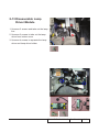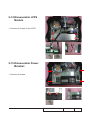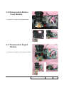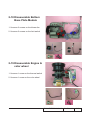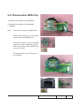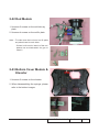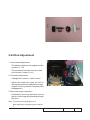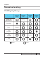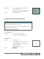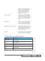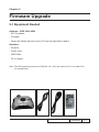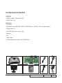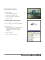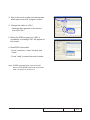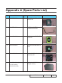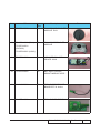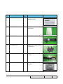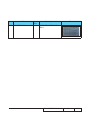
1
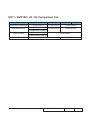
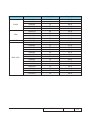
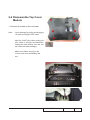
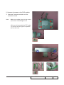
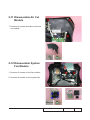
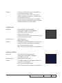
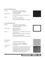
SERVICE MANUAL
DV11 / DVD100 / U2 / U3
Date
Revise Version
Description
2007.03.28
V1.0
Initial Issue
2007.07.02
V2.0
Edit 2-24, 4-4, 4-6, 4-10, 5-1, 5-3 and 5-4
2007.08.10
V3.0
Edit 5-4, 6-4, Appendix B. Add 5-5 and 5-6
2009.03.05
V4.0
Add DV11 extended models: DVD100, U2, U3
(modify 2-25 of Chapter 2 and Chapter 3)
Copyright March, 2009. All Rights Reserved P/N: 36.85E05G001
SI :
TSE:
Check:
Approved:
DV11 / DVD100 / U2 / U3 Comparison List
Parts
DV11
DVD100
TOP COVER MODULE
75.85E16G001
75.85E16G011
75.85E22G001
70.85E40GR01
70.85E39GR01
MAIN BD MODULE
LAMP COVER
REAR COVER MODULE
70.85E36GR01 (USA)
70.85E40GR01 (EMEA)
51.85E14G002 (USA)
51.85E14G001 (EMEA)
U2
U3
51.85E14G001
75.85E09G001
DV11 / DVD100 / U2 / U3
75.85E23G001
Confidential
I
Preface
This manual is applied to DV11 / DVD100 / U2 / U3 projection system. The manual gives
you a brief description of basic technical information to help in service and maintain the
product.
Your customers will appreciate the quick response time when you immediately identify
problems that occur with our products. We expect your customers will appreciate the
service that you offer them.
This manual is for technicians and people who have an electronic background. Please
send the product back to the distributor for repairing and do not attempt to do anything that
is complex or is not mentioned in the troubleshooting.
Notice:
The information found in this manual is subject to change without prior notice. Any subsequent
changes made to the data herein will be incorporated in future edition.
DV11 / DVD100 / U2 / U3 Service Manual
Copyright March, 2009
All Rights Reserved
Manual Version 4.0
DV11 / DVD100 / U2 / U3
Confidential
II
Table of Content
Chapter 1
Introduction
Highlight
1-1
Compatible Mode
1-2
Chapter 2 Disassembly Process
Equipment Needed & Product Overview
2-1
Disassemble Lamp Cover
2-2
Disassemble Lamp Module
2-2
Disassemble Top Cover Module
2-3
Disassemble Keypad Board
Disassemble Speaker Module
2-4
Disassemble Front & Back Cover Module
2-5
Disassemble EMI Front Cover
2-5
Disassemble DVD Module
2-6
Disassemble MB Module
2-8
Disassemble Air Cut Module
2-9
Disassemble System Fan Module
2-9
Disassemble Lamp Driver Module
2-10
Disassemble LVPS Module
2-11
Disassemble Power Bracket
2-11
Disassemble Bottom Cover Module
2-12
Disassemble Engine Module
2-12
Disassemble Bottom Base Plate Module
2-13
Disassemble Engine & Color Wheel
2-13
Disassemble Zoom Ring & Focus Ring
2-14
Disassemble DMD Chip
2-15
DV11 / DVD100 / U2 / U3
Confidential
2-4
III
Rod Module
2-16
Bottom Cover Module & Elevator
2-16
Rod Adjustment
2-17
Re-write Lamp Usage Hour
2-18
Chapter 3 Troubleshooting
LED Lighting Message
3-1
Main Procedure
3-2
Chapter 4 Function Test & Alignment Procedure
Test Equipment Needed
4-1
Service Mode
4-1
OSD Reset
4-1
Test Condition
4-2
Test Inspection Procedure
4-3
PC Mode
4-3
Video Performance
4-7
DVD Funcation Check
4-8
Optical Performance Measure
4-9
Others
4-11
Chapter 5 Firmware Upgrade Equipment Needed
5-1
DLP Composer Lite Setup Procedure
5-2
USB Driver Upgrade Procedure
5-4
Firmware Upgrade Procedure
5-6
DVD Region Code
5-9
DVD Code Installation Procedure
5-9
DV11 / DVD100 / U2 / U3
Confidential
IV
Chapter 6 EDID Upgrade
EDID Introduction
6-1
Equipment Needed
6-2
Setup Procedure
6-3
EDID Key-In Procedure
6-3
Appendix A
Recommended Spare Parts
I
Appendix B
Serial Number System Definition IX
PCBA Code Definition
X
DV11 / DVD100 / U2 / U3
Confidential
V
Chapter 1
Introduction
1-1 Highlight
No
Item
Description
1
Dimensions (L x W x H)
● 15.0” x 10.9” x 5.5” (379.8 x 277.8 x 138.7 mm)
2
3
Weight
Tilt Angle
4
Power Supply
5
Light source
●���������
8.3 lb
●������������
Adjustable Feet
�����������
angle Front
���������������
tilt 8° ●�� Universal
���������������������
100~240VAC +/-10%, 50-60 Hz with PFC
��������� ������ ���� ����� ����������
input
180W for Phoenix Lamp
●�� �����
Lamp ���������
could be changed
�����������
by customer,
���������������������
but should �����������
follow the
user manual instruction.
6
7
Keystone correction
Color
9
Cooling system
10
Brightness
11
Contrast
12
13
Uniformity
Throw ratio
14
Lamp door protection
15
Projection lens
16
Lamp life
17
System controller
●�� ������������
Replaceable Lamp
���������������
should be provided
������������������������������
by Coretronic or its
authorized agencies
●� Vertical: +/- 16 deg (Ref, Limited
���������� ����������������� ��������������������
by DDP2000)
●��������
Pearl ������
white ������������������
for top and black ���������������������
for side and bottom
● �������������
Advanced Air Flow
�����
Two motor fans (one blower fan and one axial fan)
Temperature control circuits with adaptive voltage control
fan speed
●� ����������
Max touch ������������
temperature ��������
follows ���������������������
UL60950-1 regulation
● Typical 1100 ANSI lm
● Minimum 900 ANSI lm
●� ����������
Full on / �����������������������
Full off :Typical 1800 :�� 1
�
● Minimum
�������������
1300 :�� 1
�������������������������
(Spoke on/Spoke off)
●� Typical Japan
�������� ����������
85% /Minimum
�����������������������
75% (Full on)
● �����
1.36 ~1.50
���������������������������������
(Projection Distance/Image Width)
�������
●� �����
Lamp �������������������������������������
power supply shuts off automatically �����������
when door
open
●���
f = 15.06 ~ 16.78 mm, F/2.8, 1.1X.
�� �������������������� �������������
●�������������������
180Watt Phoenix ������
Lamp. ������������������������������
Lamp life 1500 hours based on
Phoenix DC lamp specification
●� ����������
TI DDP2000
DV11 / DVD100 / U2 / U3
Confidential
1-
No
Item
18
Video compatibility
19
Intelligent zoom
20
SXGA / Compression
21
Power consumption
22
23
Color wheel
Lamp
24
Temperature
Description
●�����������
Standards ��: �����������
(Should be frame
�����������
lock)
PAL B,G,D,H,I,M,N
NTSC M
NTSC-Japan NTSC 4.43
SECAM
●����������
Standard �����������
TV Display �����������
Formats :
480i, 480p, 576i/p, 720p 50 & 60Hz, 1080i 50 & 60Hz Support SCART RGB via D-SUB (VGA)
●�����������
By using “TI
����������������������
DDP2000” Chips to provide
������������������
excellent quality
��������
zooming.
●�����������
By using “DDP2000”
�������������������
Chips to compress
�������������������������
SXGA image into
SVGA display
●� Full power
����� �����������
245W +-10 % at
�����������������
110Vac Standby < 12W
●� ����������������
R92/Y83/G75/W110
●� �����������
E20.6 260W Phoenix
●� Operating: 5°C -- 35°C ����������� ���� ���������
(Satisfied engineering specification & functions)
●�����������
Storage: -10°C -- 60°C
������ ��� �����
1-2 Compatible Mode
Analog
Compatibility
VGA
Resolution
V-Sync [Hz]
H-Sync [KHz]
640x350
70
31.46
640x400
60
31.46
640x480
72
37.86
640x480
640x480
720x400
720x400
75
85
70
85
37.5
43.26
31.46
37.92
DV11 / DVD100 / U2 / U3
Confidential
1-
Compatibility
SVGA
XGA
SXGA
MAC (G4)
Resolution
V-Sync [Hz]
H-Sync [KHz]
800x600
800x600
800x600
800x600
800x600
1024x768
56
60
72
75
85
60
35.15
37.87
48.07
46.87
53.67
48.36
1024x768
70
56.47
1024x768
1024x768
1280x1024
640x480
75
85
60
60
60.02
68.67
64.31
31.4
640x480
640x480
640x480
800x600
800x600
800x600
800x600
800x600
1024x768
1024x768
1024x768
1024x768
1152x870
72
75
85
56
60
72
75
85
60
70
75
85
75
37.41
37.5
43.26
35.15
37.81
48.13
46.87
53.67
48.27
56.47
60.2
68.67
68.76
DV11 / DVD100 / U2 / U3
Confidential
1-
Chapter 2
Disassembly Process
2-1 Equipment Needed & Product Overview
1. Screw Bit (+) :107
2. Hex Sleeves 5mm
3. Hex Sleeves 8mm
4. Tweezers
5. Projector
* Before you start: This process is protective level II. Operators should wear electrostatic chains.
* Note: - If you need to replace the main board, you have to get into service mode and record the lamp usage hour. please refer to section 2-25.
- As the process of DVD100 / U2 / U3 disassembling is the same as DV11, we take DV11 for example here.
DV11 / DVD100 / U2 / U3
Confidential
2-
2-2 Disassemble Lamp
Cover
1. Unscrew 1 screw on the lamp cover
2-3 Disassemble Lamp
Module
1. Unscrew 2 screws on the lamp module
DV11 / DVD100 / U2 / U3
Confidential
2-
2-4 Disassemble Top Cover
Module
1. Unscrew 6 screws on the unit base
Note: - A
void damage by pulling and dragging
IR cable and keypad FPC cable.
- Hold the CNNT plug when pulling the
FPC cable is strongly recommended.
Pulling the cable directly from the unit
will cause the cable damages.
- Make sure cables are plug in the
correct ports when assembling the
unit.
DV11 / DVD100 / U2 / U3
Confidential
2-
2-5 Disassemble Keypad
Board
1. unscrew 4 screws on the keypad
Note: - Make sure cables plug into the correct
ports when assembling the unit.
2-6 Disassemble Speaker
Module
1. Unscrew 4 screws on the speaker
DV11 / DVD100 / U2 / U3
Confidential
2-
2-7 Disassemble Front&Back
Cover Module
1. Unscrew 2 screws and take out the back
cover
2-8 Disassemble EMI Front
Cover
1. Unscrew 3 screws on the EMI front cover
DV11 / DVD100 / U2 / U3
Confidential
2-
2-9 Disassemble DVD
Module
1. Unscrew 4 screws on the system
Note: - Use two fingers to pull out the cover
- Refer to the image on the bottom right
corner to unplug the cables
DV11 / DVD100 / U2 / U3
Confidential
2-
2. Unscrew 4 screws on the DVD module.
3. U
nscrew 2 screws and take out the
connector board
Note: - Make sure cables plug into the correct
ports when assembling the unit.
- When you disassemble the FPC cable,
you should use two figures to parallel pull out the hook.
DV11 / DVD100 / U2 / U3
Confidential
2-
2-10 Disassemble MB Module
1. Unscrew 5 screws on the main board
2. Unplug the IR cable on the main board
and take out the front cover
Note: - E ach cable should be plug into the
correct ports.
- A void cables interrupt with system
fan when organizing the cables. (see
images)
- Use an electrostatic ion gun to puff
the main board connector
DV11 / DVD100 / U2 / U3
Confidential
2-
2-11 Disassemble Air Cut
Module
1. Unscrew 3 screws and take out the air
cut module
2-12 Disassemble System
Fan Module
1. Unscrew 3 screws on the fan module
2. Unscrew 4 screws on the system fan
DV11 / DVD100 / U2 / U3
Confidential
2-
2-13 Disassemble Lamp
Driver Module
1. Unscrew 2 screws and take out the lamp
line
2. Unscrew 2 screws to take out the lamp
driver from bottom cover
3. Unscrew 4 screws to separate the lamp
driver and lamp driver holder
DV11 / DVD100 / U2 / U3
Confidential
2-10
2-14 Disassemble LVPS
Module
1. Unscrew 5 screws on the LVPS
2-15 Disassemble Power
Bracket
1. Unscrew 5 screws
DV11 / DVD100 / U2 / U3
Confidential
2-11
2-16 Disassemble Bottom
Cover Module
1. Unscrew 1 screw on the bottom base
2-17 Disassemble Engine
Module
1. Unscrew 4 screws on the engine module
DV11 / DVD100 / U2 / U3
Confidential
2-12
2-18 Disassemble Bottom
Base Plate Module
1. Unscrew 3 screws on the blower fan
2. Unscrew 2 screws on the limit switch
2-19 Disassemble Engine &
color wheel
1. Unscrew 1 screw on the thermal switch
2. Unscrew 1 screw on the color wheel
DV11 / DVD100 / U2 / U3
Confidential
2-13
3. Unscrew 1 screw on the photo sensor
board
Note: - The manner of holding a color wheel
(see image)
2-20 Disassemble Zoom
Ring & Focus Ring
1. Unscrew 3 screws on the focus ring
2. Unscrew 2 screws on the zoom ring
DV11 / DVD100 / U2 / U3
Confidential
2-14
2-21 Disassemble DMD Chip
1. Unscrew 4 screws on the heatsink.
2.Unscrew 4 screws on the heatsink
bracket.
Note: - The manner of placing a DMD mask
- Use an electrostatic ion gun to puff the
engine room in the DMD mask
- If there are scrapes or dirt on the DMD
chip when using a magnifying glass to
have a close look, use an electrostatic
ion gun to clean it.
- To double check and see if the pin is
out of shape.
DV11 / DVD100 / U2 / U3
Confidential
2-15
2-22 Rod Module
1. Unscrew 2 screws on the rod hide ray plate
2. Unscrew 4 screws on the rod fix plate
Note: - To make sure that rod and rod fix plate
are placed next to each other.
- If there is dirt on the interior of the rod,
please use an electrostatic ion gun to
clean it.
2-23 Bottom Cover Module &
Elevator
1. Unscrew 2 screws on the elevator
2. When disassembling the springs, please
refer to the bottom images.
DV11 / DVD100 / U2 / U3
Confidential
2-16
2-24 Rod Adjustment
1. environment adjustment
- The distance between the engine and the
screen is 1.7 M
- This process should be done at a dark environment. (under 5 Lux)
2. Procedure adjustment
- Change the screen to “white screen.”
- Adjust the screws by using the rod on
the engine module to readjust the image.
(adjust until the yellowish or bluish parts
disappeared.)
3. Abnormal image inspection
- It should not have any abnormal color at
the rim of the image by estimating through
the eyes.
Note: To avoid over adjusting the rod.
After adjusting, add green glue to fasten it.
DV11 / DVD100 / U2 / U3
Confidential
2-17
2-25 Re-write Lamp Usage
Hour
1. Get into service mode.
- press (power > left > left > up) to get into
service mode.
2. Use “up or “down" key to select “xit", then
use "left" or "right" key to re-write the lamp
hour back to previous lamp usage hour.
3. Press “Enter"toexitt��eserv
Note: left key = decrease lamp hour
right key =increase lamp hour
DV11 / DVD100 / U2 / U3
Confidential
2-18
Chapter 3
Troubleshooting
3-1 LED Lighting Message
Power LED
(Green)
Message
Standby State
(input power cord)
Power LED
(Blue)
Temp LED
(Red)
Lamp LED
(Red)
Flashing
Normal Mode
Cooling
Flashing
Error
(Lamp failed)
Error
(Fan failed)
Flashing
Error
(Over Temp.)
Lighton
Lightoff
DV11 / DVD100 / U2 / U3
Confidential
3-
3-2 Main Procedure
No
Procedure
Symptom
- Ensure the Power Cord and AC Power Outlet are securely
connected
- Check Lamp Cover and Interrupt Switch
- Ensure all connectors are securely connected and aren’t
1
No Power
broken
- Check Lamp Driver
- Check LVPS
- Check Main Board
- Check LED Status
a. Lamp LED lights red
- Check Lamp
- Check Lamp Driver
- Check Main Board
- Check Color Wheel
2
Auto Shut Down
- Check Photo Sensor
b. Temp LED lights red
- Check Thermal Sensor
- Check Thermal Switch
- Check Fan
c. Temp LED flashing red
- Check Fan
- Check Main Board
DV11 / DVD100 / U2 / U3
Confidential
3-
No
Procedure
Symptom
- Ensure the Signal Cable and Source work
(If you connect multiple sources at the same time, use the
“Source” button on the control panel to switch)
- Ensure all connectors are securely connected and aren’t
broken
3
No Image
- Check Main Board
- Check DMD Board
- Check Color Wheel
- Check DMD Chip
- Check Engine Module
- Ensure all connectors are securely connected and aren’t
broken
- Check Lamp Module
4
No Light On
- Check Lamp Driver
- Check LVPS
5
Mechanical Noise
- Check Main Board
- Check Color Wheel
- Check Fan Module
- Check if the Main Board and the DMD Board are
assembled properly
6
Line Bar/Line Defect
- Check Main Board
- Check DMD Board
- Check DMD Chip
- Do “Reset (All data)” of the OSD Menu
- Ensure that the signal cables and source are work as well
7
Image Flicker
- Check Lamp Module
- Check Color Wheel- Check DMD Board
- Check Main Board
DV11 / DVD100 / U2 / U3
Confidential
3-
No
Procedure
Symptom
- Do “Reset (All data)” of the OSD Menu
- Adjust Color Wheel Index
8
Color Abnormal
- Check Main Board- Check DMD Board
- Check Color Wheel
- Ensure the projection screen without dirt
- Ensure the projection lens is clean
9
Poor Uniformity/
Shadow
- Ensure the Brightness is within spec
- Check rod alignment
- Check Engine Module
- Ensure the projection screen without dirt
10
Dead Pixel/Dust
(Out of spec.)
- Ensure the projection lens is clean
- Clean DMD Chip and Engine Module
- Check DMD Chip- Check Engine Module
- Ensure that the signal cables and source are work as well
11
Garbage Image
- Check Main Board
- Check DMD Board
- Remote Control
12
Remote Control/
Control Panel Failed
a.Check Battery
b.Check Remote Controller
c.IR receiver
d.Check Main Board
- Control Panel
a.Check FPC
b.Check keypad
c.Check Main Board
- Do “Reset (All data)” of the OSD Menu
13
Function Abnormal
- Check Main Board
- Check DMD Board
DV11 / DVD100 / U2 / U3
Confidential
3-
No
Symptom
Procedure
- Check if the disk is scratched.
14
Disk cannot be read
- Check if the anti-static protection of DVD Loader Module is
unsoldered.
- Check if the region code is correct or not.
- Check DVD Loader Module.
DV11 / DVD100 / U2 / U3
Confidential
3-
Chapter 4
Function Test & Alignment Procedure
4-1 Test Equipment Needed
- IBM PC with XGA resolution
- DVD player with Multi-system (NTSC/PAL/SECAM), equipped “Component”, “S-Video”, “Composite” and "HDMI."
- HDTV Source (480P, 720P, 1080i)
- Minolta CL-100
- Quantum Data 802B or CHROMA2327 (Color Video Signal & Pattern Generator)
- After changing parts, check the information below.
4-2 Service Mode
1. Turn on the projector and input the signal
2. Do the following actions sequentially to get into service mode
(1) Press power > left > left > up simultaneously.
(2) Service mode will be shown after pressing "Menu" and "Enter" for 3 seconds.
(3) After confirming the configuration, press "Menu" and exit.
4-3 OSD Reset
1. After final QC step, we have to erase all saved change again and resotre the OSD
default setting. The following actions will allow you to erase all end-users' settings and
restore the default setting:
(1) Please get into OSD menu.
(2) To execute "Reset" function.
DV11 / DVD100 / U2 / U3
Confidential
4-
4-4 Test Condition
- Circumstance brightness: Dark room less than 5.0 lux.
- Inspection distance: 1.7 m functional inspection.
- Screen size: 60 inches diagonal
- After repairing each DV11 / DVD100 / U2 / U3, the unit should be run-in (refer to the table
below)
Symptom
Normal repair
NFF
Auto shutdown
Run-in Time
2 hours
4 hours
6 hours
- Get into Burn-In Mode
* Cycle setting is based on the defect symptoms. ie: If it is NFF, the run-in time is 4 hours. You have
to set the lamp on for 50 min. and lamp off for 10 min for 4 cycles.
Press power > left > left > up
Choose Burn-In Test > enter
Lamp On (Min)
Press right key to adjust the time (50)
Lamp Off (Min)
Press right key to adjust the time (10)
Set burn in cycle
Press right key to adjust the cycle
After setting up the time, choose Burn-In mode and hit enter
Screen Defects (While replacing DMD Chip, DMD BD and MB)
< Figure: Zone A &B Definition >
DV11 / DVD100 / U2 / U3
Confidential
4-
4-5 Test Inspection Procedure
Change parts
Update
Main Board
Firmware
Version Update
v
v
Color Wheel Index
v
Color Wheel
Lamp Module
v
Reset lamp hour
v
OSD
v
EDID
v
Re-write Lamp
Hour Usage
v
v
Note: If Color appears abnormal after changing Main Board Module,
please do Color Wheel index adjustment.
4-6 PC MODE
1. Frequency and tracking boundary
Procedure - Test equipment: video generator.
- Test signal: analog 800 X 600@60Hz - Test Pattern: general-1 or master
- Check and see if the image sharpness is wellperformed.
- If not re-adjust by the following steps:
(1) Select "Frequency" function to adjust the
total pixel number of pixel clock in one line
period.
(2) Select "Tracking" function and use right or
left arrow key to adjust the value to minimize
video flicker.
- Adjust Resync or Frequency/Tracking/H. Position/V. Position to the inner screen.
Inspection item
- Eliminate visual wavy noise by Rsync, Frequency or Tracking selection.
- Check if there is noise on the screen.
- Horizontal and vertical position of the video
should be adjustable to the screen frame.
General-1
DV11 / DVD100 / U2 / U3
Master
Confidential
4-
Criteria
- If there is noise on the screen, the product is
considered as failure product.
- If there is noise on the screen, use auto or
manual “frequency” function or “tracking” function to adjust the screen.
- The PC mode functionally sure be workable
include support format with frequency and auto
detected functional will be workable.
2. Light Leak
Procedure - Test equipment: video generator.
- Test signal: analog 800 X600@60Hz - Test Pattern: gray 30 patterns
- Check if the light leaks.
* Light leak on reflective edge, eyecatcher, bondwires and exposed metal.
Gray 30
Inspection item
- Light leak check.
- Bright blemish (dirty).
Criteria
- The pattern cannot accept the color level of the
leakage is brighter than the gray 30 pattern.
- Ref. Defect specification table
Note: The defect criteria follows TI specification.
3. Blemish (Dark)
Procedure - Test equipment: video generator.
- Test signal: analog 800 x 600@60Hz.
- Test Pattern: blue 60
Inspection item
- Dark blemish check.(dirty)
Criteria
- The bright blemish is unacceptable when it appears on blue 60 pattern.
- Ref. Defect specification table
Note: The defect criteria follows TI specification.
DV11 / DVD100 / U2 / U3
Blue 60
Confidential
4-
4. Dead Pixel (Bright pixel)
Procedure - Test equipment: video generator.
- Test signal: analog 800 x 600@60Hz.
- Test Pattern: full black
Inspection item
- Bright pixel check.
Note: Frame dimension under operative zone 1
inch
Full black
Criteria
- Bright pixel is unacceptable.
- Ref. Defect specification table
Note: The defect criteria follows TI specification.
5. Dead Pixel (Dark pixel)
Procedure - Test equipment: video generator.
- Test signal: analog 800 x 600@60Hz.
- Test Pattern: full white
Inspection item
- Dead pixels check.
- White pattern (IRE=100)
- Adjacent dark pixel.
Criteria
- The number of the dead pixels should be less or
equal to 6 pixels.
- Adjacent pixel with each other is unacceptable.
- Ref. Defect specification table
Note: The defect criteria follows TI specification.
Full white
6. Focus Test
Procedure - Test equipment: video generator.
- Test signal: analog 800 x 600@60Hz
- Test Pattern: full screen or MEME Sony
Inspection item
- Focus check
Criteria
-From screen 1.7 M via visual to check the focus,
look at the entire screen, focus shall be clear,
crisp, and sharp over the entire surface of the
display pattern. (Blur word on one of the corner
after adjustment is acceptable. However, the
word should at least be recognizable.)
Full screen
MEME Sony
DV11 / DVD100 / U2 / U3
Confidential
4-
7. Color performance
Procedure
- Test equipment: video generator.
- Test signal: DVI (HDMI) 720p,1080i
- Test Pattern: Master, In focus II or SMPTE RP133
* Please refer to 4-2 to get into service mode.
Use 720P & 1080i signal, master pattern to do
HDTV test. Color cannot discolor to purple and
blue.
Inspection item
Criteria
Master
- Check if each color level is well-functioned.
- color saturation
- Screen appears normal. It should not have any
abnormal condition, such as lines appear on the
screen and so on.
- Color appears normal.
- It is acceptable to have few lines flashing at the
center and on the edge of 1080i image. However, rest of the image should appears stable.
- RGBW should all appear normal on the screen
and sort from R -G-B-W.
- Color levels should be sufficient and normal.
(the unidentified color levels on both left and
right sides should not over 8 color levels.)
- Grey level should not have abnormal color or
heavy lines.
- The PC mode functionally sure be workable
include support format with frequency and auto
detected functional will be workable
DV11 / DVD100 / U2 / U3
InFocus II
/ 64 gray RGBW
SMPTE RP-133
Confidential
4-
Defect specification table
Order
Symptom
Pattern
Black pattern
Criteria
1
Bright pixel ( dots)
A+B=0
2
Dark pixel(dots)
White pattern
3
Unstable pixel (dots)
Any pattern
4
Adjacent dark pixel
(dots)
Any pattern
5
Dark blemish (Dirty)
Blue 60 pattern
6
Bright blemish (Dirty)
Gray 30 pattern
7
Bright dot on frame
Black pattern
( IRE=O)
A+B=6
A+B=1
A+B=0
A+B=3 (diameter <1/2 inch)
A+B=3
(diameter <1/2 inch)
2
4-8 Video Performance
1. CVBS
Procedure - Test equipment: DVD player
- Test signal: CVBS
Inspection item
- Video performance test
Inspection Distance - 1.7M
Criteria
- Check any abnormal color, line distortion or any
noise on the screen.
- Check the sound from speakers.
Motion video
2. S-Video
Procedure - Test equipment: DVD player
- Test signal: S-Video
DV11 / DVD100 / U2 / U3
Confidential
4-
Inspection item
- Video performance test
Inspection Distance - 1.7 M
Criteria
- Check any abnormal color, line distortion or any
noise on the screen.
- Check the sound from speakers.
3. HDTV/ Component
Procedure - Test equipment: DVD player
- Test signal: Ycbcr/YPbPr
Inspection item
- HDTV performance test
InspectionDistance - 1.7 M
Criteria
- Check any abnormal color, line distortion or any
noise on the screen.
- Check the sound from speakers.
4. Audio Test
Procedure - Test equipment: DVD player
- Test signal: CVBS
Inspection item
- Audio performance test
Criteria
- Check the sound from speakers.
- Check “Volume” is normal
- Check “Mute” is normal
4-9 DVD Function Check
Material - DVD
Procedure
- Put DVD into DV11
- Press "play" and check if the display image is
normal
- Check DVD keypad function (FWD, REW,
STOP, Volume +/- )
DV11 / DVD100 / U2 / U3
logo
Confidential
4-
Check region
- Turn on the unit and wait until the image appears on the screen.
- press “1”, “2”, “3”, “4” buttons on remote control
to check if the region code is right or not
Criteria
- Logo image appears
check region
4-10 Optical Performance Measure
Inspection Condition
- Environment luminance: 5 Lux
- Product must be warmed up for 3 minutes
- Distances from the screen: <Max. zoom & 60 inches diagonal> 1.7 M
- Screen Size: 60 inches diagonal
- Reset to default before measurement.
1. Test equipment
Procedure - Test equipment: video generator.
- Test signal: analog 800 x600 @60Hz.
2. Brightness
Procedure - Full white pattern
- Use CL100 to measure brightness values of P1~P13.
- Follow the brightness formula to calculate
brightness values.
☼ Brightness Formula
Avg. (P1+P2+P3+...+P9) x 1.1
Criteria
Full white pattern
��•�����������
����������
495 Lumens
DV11 / DVD100 / U2 / U3
Confidential
4-
3. Full On/Full Off Contrast
Procedure
- Full white pattern & full black pattern
- Use CL100 to measure brightness values of full
white pattern P5 & full black pattern B5 ( see image: full white)
- Follow Contrast formula to calculate contrast
values.
☼ Contrast Formula
Full black pattern
P5/B5
note: P5=center of white image
Criteria
B5 = the center of black image.
��•�������
������
1300:1
4. Uniformity
Procedure
- Full white pattern
- Use CL100 to measure brightness values of
P1~P13 (see image: full white).
- Follow the Uniformity formula to calculate
average values.
☼ Uniformity Formula
ANSI Uniformity = Avg. (P1, P3, P7, P9) Criteria
P5
x 100%
• 75 %
4-9 Others
1. Functional Inspection
Keypad button
- All keypad buttons must operate
smoothly.
General- All OSD functions must be
DV11 / DVD100 / U2 / U3
Confidential
4-10
checked for functionality. When
OSD menu is displayed, there
shall be no visible peaking,
ringing, streaking, or smearing
artifacts on the screen.
Factory Default
- The factory settings (with appropriate centering, size, geometry
distortion, etc.) shall be displayed
upon “Recall” is selected from
OSD
Display Size
- All preset modes shall expand to
full screen size using OSD Horizontal and Vertical Size controls
Display Data Channel (DDC) - The purpose of the DDC test is to
verify the DDC1/DDC2B operation of the projector and to verify
Plug & Play function.
Acoustic
- High pitch sound from cooling fan
and color wheel is unacceptable.
2. Check points for exterior and print pattern
Check item
Check point
text & pattern
missing letters & pattern or blurry prints are
unacceptable.
exterior
dirt, scrape, water ripples and uneven color are
unacceptable.
buttons
stuck buttons are unacceptable.
Focus ring
Focus ring is functioning smoothly.
Logo
missing logo, missing prints and blurry prints are
unacceptable
screw
All screw sure be fixed and in right type.
DV11 / DVD100 / U2 / U3
Confidential
4-11
Check item
Check point
elevator
Elevator is well-functioned.
Stuck key is unacceptable.
pedestal
well-functioned
lamp cover
It should be locked in the correct place.
Plastic parts
Safety or warning
label
Connector
All plastic parts can not be broken and
damaged.
All safety and warning label should be visible,
including all contents.
All interface connectors should be complete and
workable.
DV11 / DVD100 / U2 / U3
Confidential
4-12
Chapter 5
Firmware Upgrade
5-1 Equipment Needed
Software : (DDP 2000- USB)
- DLP Composer
- Firmware
- Library file (library file has to put in PC and set right path in step 5)
Hardware :
- Projector
- Power code
- USB Cable
- PC or Laptop
Note: The FW Upgrade procedure for DVD100 / U2 / U3 is the same as DV11, we take DV11 for example here.
DV11 / DVD100 / U2 / U3
Confidential
5-
5-2 DLP Composer Lite Setup Procedure
1. Choose “DLP Composer Lite V6.0 Setup”
Program.
2. Click “Next” buttom
3. Read “License Agreement.”
- Choose “I aacept and agree to be bound
by all the terms and conditions of this
License Agreement.”
4.. Click “Next.”
DV11 / DVD100 / U2 / U3
Confidential
5-
5. Click “Next.”
6. Click “Next.”
7. Writing system registry values
8. Click “Finish.”
DV11 / DVD100 / U2 / U3
Confidential
5-
5-3 USB Driver Upgrade
Procedure���
1. set up
- Hold on “menu” and plug in power cord.
- When the power, lamp and temp LED
lights up, plug in USB cable into the
projector and link to the USB port of a PC.
(Power LED light in green; Temp/lamp
light in red.)
Note: The system fan and the light will not operated.
2. Execute Program
- Open the “DLP Composer Lite V6.0” folder.
- Select and double click “usbupdate.cmd”.
Note: “DLP Composer” must be closed first.
3. Press any key to continue and wait for
about 1 minute.
4. Update Successfully.
- Click “OK”.
DV11 / DVD100 / U2 / U3
Confidential
5-
5. Device Manager
- Right click “My Computer” on the desktop.
- Select “Properties” on the popup menu to
launch the “system properties” window.
- Choose “Hardware” and then click “Deve
Manger”.
6. C
lick “Jungo” to ensure “ DDP 2000” and
“Windriver” are properly installed. If not, repeat the above steps.
Note: If you have installed the USB driver, there is no need to perform this action.
DV11 / DVD100 / U2 / U3
Confidential
5-
5-4 Firmware Upgrade
Procedure
1. Set-up
- Hold on “menu” and plug in power cord .
- Once power, lamp and temp LED lights
up, plug in USB cable into the projector
and link to the USB port of a PC.
Note: T
he system fan and the light will not
operated.
2. Execute the “DLP ComposeTM” file..
3. Click “edit” and “perferences.”
4. Click “Library.”
- The library path located in the default
installation directory.
-C
:\Program Files\DLP Composer Lit 6.0
Note: If not, press “Browse” to select the right
path.
DV11 / DVD100 / U2 / U3
Confidential
5-
5. Select “Edit\preferences\Communications”
- choose “USB.” Click “OK.”
6. Choose “Flash Loader.”
- Click “Browse” to search the firmware file.
7. Selete the item “skip Boot Loader Area
(select 16KB)
- Click “Reset Bus” to erase the flash memory
8. If the firmware is ready, click “start
download” to process the firmware
upgrade.
- Click “Yes” to erase the flash memory.
DV11 / DVD100 / U2 / U3
Confidential
5-
9. When firmware upgrade process is
finished, the unit return to stand-by status.
The LED power lights on and appears blue.
- Unplug USB cable and power cord and
replug in power cable.
10. Restart the unit and get into the service
mode to check the firmware version.
( To get into service mode, please refer to
Chapter 4 Funcation Test and Alignment
Procedure.)
DV11 / DVD100 / U2 / U3
Confidential
5-
5-5 DVD region code
1. Region 1 - America
2. Region 2 - Europe, England, Japan
3. Region 3 - ROW, Taiwan, Hong Kong
4. Region 4 - South America, Australia
5. Region 5 - Pan-EMEA, Indian
6. Region 6 - China
5-6 DVD Code Installation
Procedure
1. Turn on DV11 unit and wait until the right
image shows on the screen (signal source
is from DVD loader)
2. Put the DVD code CD into DVD loader. The
CD will be running automatically.
Note: If you do not have the CD, please do the
following steps:
(1) A CD-RW burner to make the CD is
needed
(2) M
ake sure that the file name in the CD
MUST be dvdrom.bin
DV11 / DVD100 / U2 / U3
Confidential
5-
3. Please wait until the installation process
finish TheCD w
c
4. Press the number buttons, 1 to 4, on the
remote control to check if the DVD code is
correct or not
DV11 / DVD100 / U2 / U3
Confidential
5-10
Chapter 6
EDID Upgrade
6-1 EDID Introduction
Extended Display Identification Data is a VESA standard data format that contains basic information about a display device and its capabilities, including vendor information,
maximum image size, color characteristics, factory pre-set timings, frequency range limits, and character strings for the monitor name and serial number.
The information is stored in the display and is used to communicate with the system
through a Display Data Channel (DDC), which sites between the display device and the
PC graphics adapter. The system uses this information for configuration purposes, so the
monitor and system can work together.
Note: - If a display device has digital input ports, like DVI or HDMI, but without EDID in its main board, the display device will show no image while the input source is digital signal.
- The EDID Upgrade procedure for DVD100 / U2 / U3 is the same as DV11, we take DV11 for example here.
DV11 / DVD100 / U2 / U3
Confidential
6-
6-2 Equipment Needed
Software
- EDID Program (Generic V0.51)
- EDID File (*.ini)
Hardware
- Projector
- Generic Fixture (80.00001.001) f EDIDKey-in Fixture: J
- Power code x 2
- RS-232 Cable (pin to pin, F-M)
- Monitor
- PC
- VGA cable
- Power adapter for fixture (47.57702G001)
DV11 / DVD100 / U2 / U3
Confidential
6-
6-3 Setup Procedure
To Analog Port
RS232 Cable
P2
1. Connect all ports
P1
- Power adapter to fixture JP1
- Fixture P1 to PC COM1 Port
- Fixture P2 to Projector analog port
JP1
Adapter
- Power on fixture
6-4 EDID Key-In Procedure
1. Click on "EDID" to execute EDID program
2. Choose model
a. in the port selection bar, please choose
the port that you use. ie: if you use
"COM1," choose COM1 in the port
selection.
b. click on "Model."
c. Select VGA in write source
b
c
a
DV11 / DVD100 / U2 / U3
Confidential
6-
3. Key in the serial number into the barcode
blank space and click "program" button
4. Change the cable to VGA1
3
6
6
- Message box appears on the screen,
then click "OK."
4
5. When the EDID program for VGA1 is
completed, a message "OK" will appear on
the screen.
6. Read EDID information
- In the "read item," select "analog" and
"trans"
- Press "read" to check the serial number
Note: If EDID upgrade failed, push the reset
button on the EDID board and re-proceed
step 3 to step 5 in section 6-4.
DV11 / DVD100 / U2 / U3
Confidential
6-
Appendix A (Spare Parts List)
Item
P/N
Latest
Rev
C
Description
1
11.009F0G005
2
43.85E01G001
A
THERMAL SWITCH
KLIXON 125 DEGR 3
48.859DMGD13
A
DMD 800*600 PIXEL DDR FTP 0.55
4
49.82Y02G001
A
SUSON 4520 BLOWER R
TYP
5
49.83J01G001
A
70x20 SYSTEM FAN, SUNON GM1207
6
51.85E14G001 (DV11)
A
LAMP COVER TEIJIN
PC(MN-3600H)
51.85E14G001
(DVD100/U2/U3)
Photo
CNNT F 166P FOR 0.55"
SVGA LGA
DV11 / DVD100 / U2 / U3
Confidential
Item
P/N
Latest
Rev
B
Description
7
51.85E25G001
8
70.82G16GR01
A
ASSY ROD MODULE
EP7190 (RMA)
9
70.85E28GR01
A
ASSY COLOR WHEEL
MODULE FOR DV11(RMA)
10
70.85E29GR01
A
ASSY ENGINE MODULE
DV11 (RMA)
11
70.85E35GR01
A
ASSY FOCUS RING MODULE DV11 (RMA)
12
75.85E01G001
A
BUY ASSY SPEAKER
MODULE HIBOX Photo
ZOOM RING TEIJIN
PC(MN-3600H)
DV11 / DVD100 / U2 / U3
Confidential
II
Item
P/N
Latest
Rev
B
Description
13
75.85E04G001
14
75.85E06G001
A
ASSY MULTI-MEDIA
DRIVER KDRM08
15
75.85E09G001 (DV11)
A
BUY ASSY REAR COVER
MODULE
75.85E23G001
(DVD100/U2/U3)
Photo
ASSY LVPS Matritek DV11
16
75.85E08G001
A
BUY ASSY FRONT
COVER DV11
17
75.85E11G001
A
BUY ASSY BOTTOM COVER MODULE DV11
18
75.85E13G001
A
BUY ASSY INTERRUPTER SWITCH DV11
DV11 / DVD100 / U2 / U3
Confidential
III
Item
P/N
19
75.85E14G001
20
75.85E16G001 (DV11)
Latest
Rev
A
Description
BUY ASSY LENS COVER
MODULE DV11
B
BUY ASSY TOP COVER
MODULE
75.85E16G011
(DVD100)
Photo
75.85E22G001 (U2/U3)
21
75.85E18G001
A
ASSY HITACHI LAMP
DRIVER 180W
22
75.85S15G001
A
BUY ASSY CEILING
MOUNT MODULE HD70
23
80.82G06G001
D
PCBA PHOTO SENSOR
BOARD EP719 Active
24
80.85E01G001
C
PCBA DMD BD FOR DV11
DV11 / DVD100 / U2 / U3
Confidential
IV
Item
P/N
25
70.85E36GR01 (DV11)
Latest
Rev
A
Description
Photo
PCBA MAIN BD MODULE
70.85E40GR01
(DVD100)
70.85E39GR01 (U2/U3)
26
80.85E03G001
E
PCBA KEYPAD BD FOR
DV11
27
80.85E04G001
F
PCBA CONNECTOR BD
FOR DV11
28
80.85E05G001
B
PCBA FRONT IR SENSOR
BD DV11
29
80.85E06G001
B
PCBA TOP IR SENSOR
BD DV11
30
SP.85E01GC01
A
LAMP CHANGER MODULE DV11
DV11 / DVD100 / U2 / U3
Confidential
Item
P/N
Latest
Rev
A
Description
31
35.82001G111
32
36.85E04G001
A
USER'S MANUAL FOR
USA/ASIA
33
45.85E01G001
A
REMOTE CONTROL DV11
34
42.86502G101
A
ADAPTER D-SUB TRANSFORM RCA
35
42.87205G201
A
CABLE COMPOSITE
VIDEO
36
35.52302G091
A
LABEL CARTON 108*92
BLANK
Photo
LABEL CARTON 3"*3"
BLANK PJ885
DV11 / DVD100 / U2 / U3
Confidential
VI
Item
P/N
Latest
Rev
A
Description
37
35.00040G001
38
35.00041G001
A
LABEL 35mm,YELLO
39
35.00042G001
A
"FRAGILE" TAPE 60mm*50Y*0.05mm
40
56.85E01G001
A
CUSHION DV11
41
55.85E01G001
A
CARTON OPTOMA LOGO
DV11
42
35.85E01G001
A
SPEC LABEL 104*65 DV11
Photo
LABEL 30mm,GREEN
DV11 / DVD100 / U2 / U3
Confidential
VII
Item
43
P/N
35.85E03G001
Latest
Rev
A
Description
Photo
LICENCE LABEL 70*50
DV11
DV11 / DVD100 / U2 / U3
Confidential
VIII
Appendix B
I. Serial Number System Definition
Serial Number Format for Projector
Q
85E
7
04 E
1
2
3 4
5
AAAA C
6
7
0001
8
1
:
Q = Optoma
2
:
86E = Project code
3
:
7 = Last number of the Manufacture year (ex:2007 = 7)
4
:
04 = week of the year ( ex: the forth month of the year = 04)
5
:
E = Checking EDID code ( “E” = EDID code is for EMEA )
6
:
AAAA = not-defined
7
:
C = Manufacture factory (TW or CPC)
8
:
0001 = Serial code
EX: Q85E714AAAAAC0001
This label represents the serial number for DV11. It is produced for USA at CPC on
fourteenth week of 2007. Its serial code is 0001.
DV11 / DVD100 / U2 / U3
Confidential
IX
II. PCBA Code Definition
PCBA Code for Projector
A B
1
XXXXXXXXXX
2
3
1
:
ID
2
:
Vendor Code
3
:
P/N
4
:
Revision
5
:
Date Code
6
:
S/N
C
4
XXX 5
EEEE
6
DV11 / DVD100 / U2 / U3
Confidential