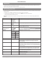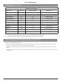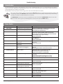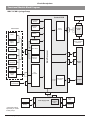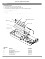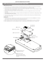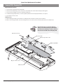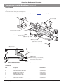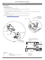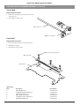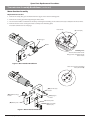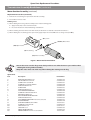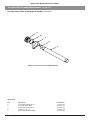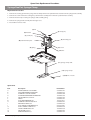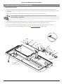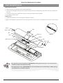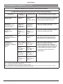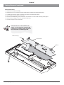
1
®
®
IVAC PCAM Syringe Pump
Technical Service Manual
This manual has been prepared for use by qualified service personnel only.
Cardinal Health cannot accept any liability for any breakdown or deterioration in
performance of parts or equipment resulting from unauthorised repair or modification.
t
Cardinal Health, 1180 Rolle, Switzerland
Alaris®, IVAC® and PCAM® are registered trademarks of
Cardinal Health, Inc. or one of its subsidiaries.
All other trademarks belong to their respective owners.
© 2005-2006 Cardinal Health, Inc or one of its subsidiaries. All rights reserved.
IVAC® PCAM® Syringe Pump
2/106
1000SM00017 Issue 2
Contents
Chapter 1 Introduction & Start Up
4
Chapter 2 Configuration & Calibration
13
Chapter 3 Routine Maintenance
26
Chapter 4 Troubleshooting
38
Chapter 5 Circuit Descriptions
42
Chapter 6 Spare Parts Replacement Procedures
47
Appendix A Specifications
83
Appendix B Spare Parts Listing
90
Appendix C Configured Options & Drug Protocol Rec.
97
Appendix D Service Centres
100
Appendix E Disposal
102
Appendix F Document History
105
IVAC® PCAM® Syringe Pump
3/106
1000SM00017 Issue 2
Chapter 1
Introduction & Start Up
In this chapter
Introduction
5
General Precautions
6
Front Panel, Controls and Indicators
7
Main Display
8
Loading a Syringe
9
Starting the Pump
10
Modifying a Preset Protocol
10
Basic Features
11
Printer Set Up
12
Patient Hand Set
12
Introduction & Start Up
Introduction
The IVAC® PCAM® Syringe Pump is designed to provide a small, self-administered dose of analgesic, as and when the patient demands
it by activating a hand operated button. The clinician can select limits for various parameters, including the size of each individual
dose, the minimum time between doses and the number of doses allowed during a period. In parallel to the patient controlled
operation the pump allows the clinician to set an automatic loading dose which will be delivered at the onset of treatment. Similarly a
continuous background infusion which is delivered irrespective of the patients demands for analgesia, can also be selected.
In addition, the pump will automatically record valuable information about each patients treatment and their individual demands for
analgesia. This allows further analysis of the frequency with which analgesia is being requested, the total dose delivered etc.
Product Familiarity
Prior to operation of the pump and prior to attempting any repairs or servicing, carefully read the Directions for Use (DFU)
As part of continuous improvement, product enhancements and changes are introduced from time to time.
Purpose of this Manual
This Technical Service Manual describes how to set up, test and maintain the IVAC® PCAM® Syringe Pump. This manual is intended for
use by personnel experienced in medical equipment testing and maintenance procedures.
Conventions Used in this Manual
BOLD
Used for pump Display names, access codes, controls and indicators referenced in this manual, for
example, GENERAL OPTIONS menu, access code 251, LOCK 1 keyswitch.
'Single quotes'
Used to indicate cross-references made to another section of this manual. For example, see Chapter
2, 'Configuration & Calibration'.
underline
Used to indicate links to another section of this manual.
Italics
Used to refer to other documents or manuals. For example, refer to the relevant Directions for Use (DFU)
for further information. Also used for emphasis, for example, ...position the narrow end of the tool...
Wherever this symbol is shown a Hints & Tips note is found. These notes provide useful advice or
information that may help to perform the task more effectively.
Wherever this symbol is shown a Toolbox note is found. These notes highlight an aspect of test or
maintenance that is important to know about. A typical example is drawing attention to a software
upgrade that should be checked that it has been installed.
IVAC® PCAM® Syringe Pump
5/106
1000SM00017 Issue 2
Introduction & Start Up
General Precautions
w
Prior to using this pump, carefully read the Operating Precautions described in the Directions for Use (DFU).
This pump contains static-sensitive components. Observe strict precautions for the protection of static
sensitive components when attempting to repair and service the pump.
An explosion hazard exists if the pump is used in the presence of flammable anaesthetics. Exercise care to
locate the pump away from any such hazardous sources.
Dangerous Voltage. An electrical shock hazard exists if the casing of the pump is opened or removed. Refer
all servicing to qualified service personnel.
M
This pump is protected against the effects of high energy radio frequency emissions and is designed to
be fail safe if extremely high levels of interference are encountered. Should false alarm conditions be
encountered, either remove the source of the interference or regulate the infusion by another appropriate
means.
If the pump is dropped, subjected to excessive moisture, humidity or high temperature, or otherwise
suspected to have been damaged, remove it from service for inspection by qualified service personnel.
IVAC® PCAM® Syringe Pump
6/106
1000SM00017 Issue 2
Introduction & Start Up
Front Panel, Controls and Indicators
Front Panel
Controls and Indicators
H
START
Press to start the infusion. The green
LED will flash during infusion.
STOP
Press to stop/hold the infusion. The
amber LED will be lit while on hold.
BATTERY
AC POWER
When illuminated, indicates that
the pump is running on the internal
backup battery. When flashing,
indicates that the battery power is
low, with less than 30 minutes of use
remaining.
W
J
When illuminated, indicates that the
pump is connected to an AC power
supply and the battery is being
charged.
PURGE/
BOLUS
HISTORY
Press to display PCA demands
and drug infused history
graphs, 24 hour review and
event log.
PRINT
Press to print patient history.
Note: A suitable printer must be
connected to the pump.
LOCK 1
Insert key into LOCK 1
keyswitch and turn key to
switch between OFF, SET and
RUN positions.
OFF
R
Q
S
PLUS/MINUS
BUTTONS
ARROW
BUTTONS
OFF - Turns the power off.
Use to move cursor and to increase
or decrease values shown on main
display.
Use as softkeys in conjunction with
the prompts shown on the display.
For example, to select the CALIBRATE
option.
Press and hold both buttons to
purge the extension set during
set up. See 'Basic Features' for
further information.
SET - Use to select or modify
protocols and to access
configuration and test routines.
SET
RUN - Use to start the infusion.
RUN
Note: Switching from RUN
mode to SET mode without
first pressing the STOP button
automatically stops the
infusion.
LOCK 2
Insert key into LOCK 2 and
turn key clockwise to open the
syringe cover.
This key lock is located
on the left side of the
pump
IVAC® PCAM® Syringe Pump
7/106
1000SM00017 Issue 2
Introduction & Start Up
Main Display
Main Display
Example Software V3R2
Current Protocol
Pump Status
Volume Infused
(Mass/Volume)
Time
13:07
PCA AVAILABLE
DEMANDS
TOTAL
GOOD
PCA Demand
Status
Pumping
Pressure Icon*
DRUG INFUSED
1.0 μg
0.1 ml
1
1
BD PLASTIPAK
50 ml
Maximum
Dose Icon*
PROTOCOL
Syringe Type/Infusion Rate
View Protocol Summary
Example Software V2R8
Current Protocol
Pump Status
Time
Volume Infused
(Mass/Volume)
13:07
PCA AVAILABLE
DEMANDS
TOTAL
GOOD
PCA Demand
Status
DRUG INFUSED
PCA DOSE
1.0 ml
MORPHINE 1
1.0 mg/ml
1.0 ug
0.5 ml
1
1
LOCKOUT
5 min
CONTINUOUS
0.0 ml/h
Pumping
Pressure Icon*
Maximum
Dose Icon*
Protocol Summary
Protocol Summary Screen
Example: Software V3R2 only
PROTOCOL
MORPHINE
1.0 mg/ml
LOADING
0 μg
PCA DOSE
1.0 mg
LOCKOUT
2 min
DOSE LIMIT
50.0 mg IN 4 h
CONTINUOUS
0 μg/h
DOSE RATE
STAT
QUIT
* These icons are not displayed when disabled.
IVAC® PCAM® Syringe Pump
8/106
1000SM00017 Issue 2
Introduction & Start Up
Loading a Syringe
1. Open the cover by turning the key in LOCK 2.
2. Squeeze the finger grips together on the plunger holder and slide the mechanism to the left.
3. Lift the syringe clamp and rotate to the left.
4. Insert the syringe into the slots on the plunger holder (see Figure 1).
5. Squeeze the finger grips on the plunger holder and slide the mechanism to the right until the syringe barrel flange locates into the
V slot (see Figure 2).
Ensure that the syringe is advanced until the syringe barrel flange touches the front of the V slot
closest to the syringe clamp. This is important to prevent delay at the start of the infusion.
6. Release the finger grips. Apply gentle pressure on the plunger holder to ensure that the drive is engaged.
7. Rotate the syringe clamp until it locks onto the syringe barrel (see Figure 2).
8. Check that the syringe plunger and syringe barrel flange are correctly located into their slots.
Syringe clamp
Syringe barrel
Syringe barrel flange
Syringe plunger
Plunger holder
Finger grips
Syringe clamp shown
locked onto syringe barrel
Syringe inserted
into plunger holder slots
V slot
Syringe barrel flange
Figure 2.
Figure 1.
IVAC® PCAM® Syringe Pump
9/106
1000SM00017 Issue 2
Introduction & Start Up
Starting the Pump
1. Connect the pump to AC Mains.
2. Open the cover by turning the key in LOCK 2.
3. Load the syringe. See instructions in previous section.
4. Power the pump ON by switching LOCK 1 to the SET position.
5. NEW PATIENT? NO retains patient data then displays the last protocol used. YES clears previous patient data then displays preset
protocol A.
6. Check the protocol displayed. If required, select the NEXT PROTOCOL option to choose an alternative preset protocol, or select the
MODIFY PROTOCOL option to adjust the current protocol. See 'Modifying a Preset Protocol' below for further information.
7. Switch LOCK 1 to the RUN position and remove the key.
8. CONFIRM PROTOCOL. Select OK.
9. CONFIRM SYRINGE. Select OK.
10. Purge (cover must be open): Press and hold the W buttons together.
11. Close the cover.
12. Connect the pump to test equipment as required (see Chapter 2, 'Configuration & Calibration' and Chapter 3, 'Routine
Maintenance').
13. Press the H button to start operation.
Modifying a Preset Protocol
1. Switch LOCK 1 to the SET position. PROTOCOL SUMMARY is displayed.
2. Select the MODIFY PROTOCOL option (this option is not available when disabled). The current protocol parameters/values are
listed.
3. Use the R Q buttons to move up/down the list of parameters. To change a parameter, highlight it and select ALTER. Use the R
Q buttons to toggle the values then select OK to confirm and return to the PROTOCOL SUMMARY. Note: A modified protocol
has no preset letter in the top left corner of the PROTOCOL SUMMARY.
Note: See 'Preset Protocol Setup' in Chapter 2 for details of protocol parameters.
If enabled, an additional 'generic' drug with parameter limits set to maximum values can be selected
when modifying protocols. Indicated by the drug name
XXX DRUG
, the drug can be selected
from the preset list of drug names.
IVAC® PCAM® Syringe Pump
10/106
1000SM00017 Issue 2
Introduction & Start Up
Basic Features
Purge
Press and hold the W buttons together to deliver a limited volume of fluid in order to purge
the extension line prior to being conected to the patient.
The purge feature cannot be activated when the cover is closed
Ensure the extension line is disconnected from the patient before purging the
line
Alarms are not disabled during a purge operation
Clinician Over-ride
Press and hold the T button for 2 seconds then enter the pre-programmed clinician over-ride
code to use this feature. Clinician over-ride can be used in RUN mode to administer an additional
bolus dose or a continuous background infusion of a limited dose and duration, for example, during the
PCA lock out period. It can also be used in SET mode to allow modification of the pre-set PCA Protocol
when this option has been disabled.
For further information, see 'Access Codes' in Chapter 2.
If the over-ride code is incorrectly entered more than three times, the event
CLIN. ACCESS TAMPER is logged in the event log and a warning appears on the
Display
Delivery of the clinician over-ride continuous infusion will automatically halt
while a Patient or Clinician over-ride bolus is being administered
To cancel clinician over-ride during delivery, press the STOP button then select
YES
History
Print
Pressing the J button provides records of patient history and events since NEW PATIENT was last
selected:
Press x 1 to display an hour-by-hour record of the number of good/failed PCA demands and
the total drug infused over the last 24 hours
Press x 2 to display a graph of the good/failed PCA demands over the last 24 hours
Press x 3 times to view a graph of the total drug infused over the last 24 hours
Press x 4 times to view the event log
With a suitable printer connected (see 'Printer Set Up' on the following page), pressing the
button provides printouts of Patient History, Protocol Summary and the Event Log. Refer to the
DFU for detailed printing instructions.
Notes:
1) Access to the full Event Log can be enabled by entering access code 794.
2) Continuous printing can be configured, see 'General Options (251)'.
Pressure
When enabled, this icon is shown on the Display. It provides a visual indicator of current
pumping pressure and pressure level at which the alarm will operate.
Maximum Dose
H
IVAC® PCAM® Syringe Pump
When enabled, this icon is shown on the Display. It provides a visual indication of the
amount of drug administered during the limit period (as shown to the left of the icon).
If the dose limit reaches the alarm level, the bottle icon will appear full, the pump will
stop infusing and the message Max Dose Limit is displayed. The icon will flash until the
dosing is less than the maximum dose limit. Clinician over-ride is always available.
11/106
1000SM00017 Issue 2
Introduction & Start Up
Printer Set Up
To set up a printer, fit a suitable printer with a serial interface cable and connect to the pump. See list of recommended printers below.
See also PRINT button functions on previous page.
Cable Requirements
RS232 9-pin D type (1000SP01008)
Wiring connections
GND PWR1 TXD2 RXD2 ALM IN
5 4 3 2 1
Pump
Printer
Female
6 NC7 CTS1
8 TXD1
9
NC
Male
Pin 5
GND
Pin 5
GND
Pin 8
CTS1
Pin 8
CTS1
Pin 9
TXD1
Pin 3
RXD1
Recommended printers
Seiko DPU-414, thermal printer (use cable 1000SP01184)
Citizen N60 (use cable 5000SP00010)
Canon Bubblejet (use cable 5000SP00008). Note: A serial to parallel adapter is required.
Continuous Printing
To configure continuous printing of events as they occur, enable the CONTINUOUS PRINT option in GENERAL OPTIONS.
Patient Hand Set
The electronic patient hand set is designed to be ambidextrous and suitable for both adult and paediatric use.
The indicator light can be configured to show when the PCA dose is available or being delivered. Should the clinical
situation require it, the indicator light can be disabled. The PCA button will provide feed-back on all, or just good
demands. See Chapter 2, 'General Options' for HANDSET MODE configuration details.
The patient handset does not contain any latex.
The hand set connector is a latching (but non-locking) connector. To remove, hold the body of the
connector and pull away from the pump. If required, the pump can be operated in continuous or
clinician over-ride modes without the hand set connected.
Note: An alarm warning will operate if the hand set is disconnected from the pump while it is in
operation, or when the handset is connected to the pump with the PCA button depressed.
IVAC® PCAM® Syringe Pump
12/106
1000SM00017 Issue 2
Chapter 2
Configuration & Calibration
In this chapter
Access Codes
14
Entering an Access Code
14
Configuration Options (251)
15
Drug Names and Safety Limits Set Up (251)
16
General Options (251)
17
Preset Protocol Set Up (251)
19
Syringe Range Selection (359)
20
Language Selection (359)
20
Setting the End of Infusion (EOI) Position
21
Calibration Procedures
22
Syringe Size Calibration (243)
22
Occlusion Calibration (717)
23
Battery Charge Circuit Verification
25
Clearing Internal RAM (611)
25
Configuration & Calibration
Access Codes
The syringe pump software contains a number of configuration and test routines that can be accessed using a technical access code as
shown in the table below.
Code
Title
Description
111*
HOSPITAL NAME
Configure name of hospital/ward to be displayed when pump is powered on and
when pump is in 'sleep' mode (when DISPLAY SLEEP is enabled).
To set the hospital name, use the R Q buttons to toggle through characters and
the S button to adjust, then select OK to store.
123
SELF TEST
Self test routine begins from the start. See Chapter 3, 'Routine Maintenance' for
further information.
124
SELF TEST
Self test routine begins at internal PSU voltage test.
125
SELF TEST
Self test routine begins at display test.
126
SELF TEST
Self test routine begins at declutch test.
127
SELF TEST
Self test routine begins at handset test.
167
COMMS LEARN MODE
Configuration set via comms interface.
168
COMMS TEACH MODE
Configuration output to another device (pump).
243
SYRINGE SIZE CALIBRATION
Syringe size measurement calibration. See 'Calibration Procedures' on the following
pages for instructions.
251
CONFIGURATION OPTIONS
MENU
Configuration of drug limits, options, protocols and real-time clock. See
'Configuration Options (251)' on the following pages for further details.
359
BUILD CONFIGURATION
Configure language and syringe range.
376
SERVICE LOG
Review and clear service log errors, hours of battery use and hours of pump on
time. To reset the service log to zero press the RESET softkey.
501**
MASS DOSING
Enable mass dosing. Drugs and protocols use mass dose mode.
502**
VOLUME DOSING
Enable volume dosing. Drugs and protocols use a mix of mass and volume.
611
TOTAL MEMORY CLEAR
Reset memory. Note that the pump will require full calibration.
717
OCCLUSION CALIBRATION
Occlusion calibration. See 'Calibration Procedures' on the following pages for
instructions.
794
FULL EVENT LOG
Enable access to full Event Log.
835
MODIFY CLINICIAN CODE
Change the 3-digit clinician over-ride code.
* This option is not available on pumps with software version V2R8 and below.
** These options are no longer in use on pumps with software version V3R2 and above. See DOSE MODE in 'Drugs and Safety
Limits' and MIX MASS & VOL MODES in 'General Options (251)'.
Entering an Access Code
Each menu (and certain individual options) has its own three-digit technical access code which is entered using the following
procedure:
1. Hold down the H button and switch LOCK 1 to the SET position.
2. When the display shows ACCESS CODE 0 0 0, release the H button.
3. Enter the required access code "XXX" using the R Q buttons in conjunction with the S button (to select the NEXT option to
move through the digits).
4. When the required code is shown, select the ENTER option to confirm.
IVAC® PCAM® Syringe Pump
14/106
1000SM00017 Issue 2
Configuration & Calibration
Configuration Options (251)
Enter the access code 251 (see 'Entering an Access Code' on the previous page for instructions). The CONFIGURATION OPTIONS menu
is displayed:
CONFIGURATION OPTIONS MENU
Option
Description
DRUG NAMES AND SAFETY LIMITS
Set drug names and limits. See the next section for further details.
GENERAL OPTIONS
See 'General Options (251)' for further details.
PROTOCOL DEFAULT SET-UP
Set default protocol and alter preset protocols. See 'Preset Protocol Set Up' for further
details.
CLOCK SET
Set the internal clock.
To set the clock, use the R Q buttons and the S button to adjust, then select OK to
store.
The internal clock is the reference against which patient history and
events are stored. Patient history should always be recorded and if
required, printed prior to changing the clock.
Changing the clock will automatically:
Reset the time and date against which all new patient history is
stored and may affect the presentation of the history graphs.
Clear previous patient data. Only NEW PATIENT? YES will be
available at start up.
IVAC® PCAM® Syringe Pump
15/106
1000SM00017 Issue 2
Configuration & Calibration
Drug Names and Safety Limits Set Up (251)
1. Enter the access code 251 to display the CONFIGURATION OPTIONS menu.
2. Select DRUG NAMES AND SAFETY LIMITS using the R Q buttons then select ENTER. DRUG 1 is displayed.
3. Select NEXT DRUG to choose another drug or select MODIFY DRUG to modify the current drug, as detailed below. Alternatively,
select QUIT to return to the CONFIGURATION OPTIONS menu.
4. Step through each DRUG option (see table below) and modify as required.
Use the R Q buttons to toggle/select a value then select OK to confirm and continue to the next option.
Use the S button at any time to go back to the previous option.
5. When set up is complete, switch LOCK 1 to the OFF position.
DRUG NAMES AND SAFETY LIMITS
DRUG option
Description
DRUG NAME
Enter drug name.
Use the R Q buttons in conjunction with the S button (to go to the next drug
name letter).
DOSE MODE*
Select the dose mode:
VOLUME
Volume mode. Drugs and protocols use volume based units. Not
available when MIX MASS & VOL MODES is disabled.
MASS
Mass mode. Drugs and protocols use mass based units only.
MINIMUM: DRUG CONC.
Set the minimum drug concentration between 1 μg/ml and 999 μg/ml or 1.0 mg/ml
and 99.9 mg/ml. OFF is also available in Volume mode.
MAXIMUM: DRUG CONC.
Set the maximum drug concentration between 1 μg/ml and 999 μg/ml or 1.0 mg/
ml and 99.9 mg/ml. Maximum value cannot be set below the minimum value.
MINIMUM: LOCKOUT PERIOD
Set the minimum lockout period (0 - 180 minutes).
MAXIMUM: LOCKOUT PERIOD
Set the maximum lockout period (0 - 180 minutes). Maximum period cannot be set
below minimum period.
MINIMUM: PCA DOSE
Set the minimum PCA dose. In Mass mode - between 0 μg and 999 μg or 1.0 mg
and 99.9 mg. In Volume mode, between 0.0 ml and 99.9 ml.
MAXIMUM: PCA DOSE
Set the maximum PCA dose. In Mass mode between 0 μg and 999 μg or 1.0 mg and
99.9 mg. Volume mode between 0.0 ml and 99.9 ml.
MAXIMUM: CONTINUOUS
Set the maximum continuous dose. In Mass mode - between 0 μg/h and 999 μg/h
or 1.0 mg/h and 99.9 mg/h. In Volume mode - between 0.1 ml/h and 25.0 ml/h
(V2R8 or below), between 0.1 ml/h and 35.0 ml/h (V3R2 or above and for syringes
>50ml).
MAXIMUM: LOADING DOSE
Set the maximum loading dose. In Mass mode - between 0 μg and 999 μg or 1.0
mg and 99.9 mg. In Volume mode - between 0.0 ml and 99.9 ml.
MAXIMUM: MAX LIMIT
Set the maximum limit. In Mass mode - between 0 μg and 999 μg or 1.0 mg and
999 mg. In Volume mode - between 0.0 ml and 999 ml.
MAXIMUM: CLINICIAN BOLUS
Set the maximum clinician bolus dose. In Mass mode - between 1 μg and 999 μg or
1.0 mg and 99.9 mg. In Volume mode - between 0.1 ml and 99.9 ml.
* This option is not available on pumps with software version V2R8 and below.
Note: For pumps with software version V2R8 or earlier, the options may vary, or will not be available. Refer to the
relevant DFU for comprehensive information.
IVAC® PCAM® Syringe Pump
16/106
1000SM00017 Issue 2
Configuration & Calibration
General Options (251)
1. Enter the access code 251 to display the CONFIGURATION OPTIONS menu.
2. Select GENERAL OPTIONS using the R Q buttons then select ENTER.
3. Use the R Q buttons to toggle/alter a value then select NEXT to move to the next option. Select QUIT at any time to go back to
GENERAL OPTIONS menu.
4. When set up is complete, switch LOCK 1 to the OFF position.
GENERAL OPTIONS
Software version: V3R2
Option
1.
Description
ICONS ON DISPLAY
YES:
NO:
H
(Pressure) and
(Max dose) icons are shown on the Display.
The
No icons are shown on the Display.
2.
PROTOCOLS IN USE
Set the number of preset protocols to be available (1 to 10).
3.
MODIFY PROTOCOL
YES:
NO:
4.
HANDSET MODE
MODE
BEEP
Handset light:
PCA STOPPED
PCA AVAILABLE
PCA DELIVERING
PCA LOCKOUT
Allows protocols to be modified in SET mode.
MODIFY PROTOCOL option disabled (removed from SET mode).
A
B
C
GOOD
ALL
ALL
OFF
ON
FLASH
OFF
ON
ON
ON
ON
OFF
ON
FLASH
ON
5.
DELAYED CALL BACK
YES:
NO:
Call-back alarm can be delayed (10 - 90 minutes).
Call-back will be cancelled (up to 2 minutes, or extended to 15 minutes).
6.
DISPLAY SLEEP
YES:
NO:
During operation, Display goes blank (into sleep mode) after 2 minutes.
Display stays on during operation.
7.
CHIRP LOW ALARMS
YES:
NO:
"Chirp" alarm occurs during use of battery/near end of battery.
No "chirp" alarm during use of battery/near end of battery.
8.
CONTINUOUS INFUSIONS
YES:
NO:
CONTINUOUS infusion option enabled in PROTOCOL set up.
Continuous infusions are not available. Option not available in PROTOCOL set
up.
9.
LOADING DOSES
YES:
NO:
LOADING DOSE option enabled in PROTOCOL set up. To activate this option,
NEW PATIENT is confirmed. Start the PCA.
Loading doses are not available.
10.
MAX DOSE LIMITS
YES:
NO:
MAX LIMIT option enabled in PROTOCOL set up.
Dose limits are not available. Option not available in PROTOCOL set up.
11.
VARIABLE DOSE RATES
YES:
NO:
PCA DELIVERY option enabled in PROTOCOL set up
Variable PCA doses not available.
12.
COMMS PUMP IDENTITY
Set pump identity for use with remote communications (000 to 127).
13.
COMMS ENABLED
YES:
NO:
RS232 communications enabled.
RS232 communications disabled.
14.
NURSE CALL
YES:
NO:
Nurse Call feature enabled (hardware feature allowing pump to communicate
with the hospital's nurse call system, typically linked to central nurse's station).
Nurse Call feature disabled.
15.
NURSE CALL INVERTED
YES:
NO:
Nurse call hardware output is inverted.
Nurse call hardware output normal.
16.
CONTINUOUS PRINT
YES:
NO:
Enables printing of events as they occur.
Continuous printing disabled.
17.
DEFAULT SYRINGE
Set default syringe type:
BD PLASTIPAK
IVAC
TERUMO
B. BRAUN OMNIFIX
MONOJECT
R.R PRONTO
BD WORLDWIDE
ONCE
IVAC® PCAM® Syringe Pump
FRESENIOUS INJECT.
RAPIJECT
PHARMA-JECT
BD PRECISE
BRAUN PERFUSOR*
JANPOL*
* with options kit fitted
17/106
1000SM00017 Issue 2
Configuration & Calibration
General Options (251) continued
GENERAL OPTIONS (continued)
Software version: V3R2
Option
Description
18.
LOCK SYRINGE TYPE
YES:
NO:
Syringe type locked to default syringe type (as set in previous option).
Syringe type not locked to default syringe type - can be changed.
19.
QUIET MODE
YES:
NO:
Pump in quiet mode.
Pump in normal mode.
20.
GENERIC DRUG ENABLED
YES:
NO:
XXX DRUG
) is available when modifying
Generic drug (indicated by
protocols. See 'Preset Protocol Set Up' for further details.
Generic drug is not available.
21.
MAX DOSE LIMIT ALARM
YES:
NO:
Pump alarms when the maximum dose limit is exceeded.
Pump does not alarm when the maximum dose limit is exceeded.
22.
MIX MASS & VOL MODES
YES:
NO:
Drugs can be set in either Mass mode or Volume mode.
All drugs and protocols are in Mass mode only.
Notes:
1) For pumps with software version V2R8 or earlier, the options may vary, or will not be available. Refer to the relevant DFU for
comprehensive information.
2) For default settings, refer to Appendix C, 'Configured Options and Drug Protocol Records'.
IVAC® PCAM® Syringe Pump
18/106
1000SM00017 Issue 2
Configuration & Calibration
Preset Protocol Set Up (251)
The number of protocols available for use is configured in GENERAL OPTIONS.
1. Enter the access code 251 to display the CONFIGURATION OPTIONS menu.
2. Select PROTOCOL DEFAULT SET-UP using the R Q buttons then select ENTER. PROTOCOL DEFAULT A is displayed.
3. Select NEXT PROTOCOL to choose another protocol or select MODIFY PROTOCOL to modify the current protocol, as detailed
below. Alternatively, select QUIT to return to the CONFIGURATION OPTIONS menu.
4. Use the R Q buttons to move up/down the list of parameters (see table below).
To enter a parameter, highlight it and select ALTER. Where relevant, the limits set in DRUG NAMES AND SAFETY LIMITS are
displayed.
Use the R Q buttons to toggle/select a value then select OK to confirm. Alternatively, use CANCEL to quit.
Select OK at any time to return to PROTOCOL DEFAULT.
5. When set up is complete, switch LOCK 1 to the OFF position.
PROTOCOL DEFAULT SET-UP
PROTOCOL parameter
Description
DRUG NAME
Select the drug. Use the R Q buttons to step through the names of the available drugs (as
set up in DRUG NAMES AND SAFETY LIMITS).
MASS DRUG
If enabled, a generic drug is available, indicated by
(only available when MIX MASS & VOL MODES option is enabled).
or
VOL DRUG
Important: The parameter limits of the generic drug are automatically set to the maximum
value.
DRUG CONC.
Set the drug concentration between the minimum/maximum limits set for the selected drug.
PCA DOSE
Set the PCA dose between the minimum/maximum limits set for the selected drug.
LOCKOUT PERIOD
Set the lockout period between the minimum/maximum limits set for the selected drug.
OCCLUSION LEVEL
Set the occlusion level (L0 to L10).
CONTINUOUS*
Set the continuous rate, below the maximum continuous rate limit set for the selected drug,
or 35ml/h (for syringes >50ml), 20ml/h (for syringes <50 ml and all syringes on pumps with
V2R8 or below), whichever is lowest.
LOADING DOSE*
Set the loading dose, below the maximum loading dose set for the selected drug.
MAX LIMIT*
Set maximum dose, below the maximum max dose set for the selected drug.
LIMIT DURATION*
Set the maximum cumulative period (1 to 8 hours).
PCA DELIVERY*
Set the PCA delivery rate. STAT rate 100 ml/h (80 ml/h for 20 ml syringes), or set by delivery
time (1 to 60 minutes).
* These options are not available if disabled.
Note: For pumps with software version V2R8 or earlier, the options may vary, or will not be available. Refer to the
relevant DFU for comprehensive information.
IVAC® PCAM® Syringe Pump
19/106
1000SM00017 Issue 2
Configuration & Calibration
Syringe Range Selection (359)
Configure the pump to use one of the three standard disposable syringe ranges, as listed in the table below.
Ensure that the required options kit is fitted to the pump before selecting the syringe range.
1. Enter the access code 359. See 'Entering an Access Code' for instructions. The display will show the current syringe range.
2. Use the R
Q buttons to select the required syringe range:
Syringe Range
Syringe Types
Size (ml)
UNIVERSAL
BD PLASTIPAK
20, 30, 50
IVAC
50, 100
TERUMO
20, 30, 50
BRAUN OMNIFIX
20, 30, 50
MONOJECT
20, 30, 50
RR PRONTO
20, 30, 50
BD WORLDWIDE
20, 30, 50
ONCE
50
FRESENIUS INJECT.
50
RAPIJECT
50
PHARMA-JECT
50
BD PRECISE
20, 50
BRAUN PERFUSOR
B BRAUN PERFUSOR
50
JANPOL
JANPOL
50
3. Turn LOCK 1 to OFF to complete the configuration.
Language Selection (359)
Configure the pump's language used for messages shown on display.
1. Enter the access code 359. See 'Entering an Access Code' for instructions. The display will show the current syringe range.
2. Press NEXT to go to language selection.
3. Use the R
Q buttons to select the required language:
4. Turn LOCK 1 to OFF to complete the configuration.
IVAC® PCAM® Syringe Pump
20/106
1000SM00017 Issue 2
Configuration & Calibration
Setting the End of Infusion (EOI) Position
Use the following procedure to check and to set the EOI point.
1. Enter the access code 126 (see 'Entering an Access Code' for instructions).
2. Select NEXT to step through the self-test routines until the display reads EOI opto: x (where x is the current status of the EOI
detector).
3. Move the plunger holder to the right. The display will read EOI opto: 0
4. Load an empty 50ml syringe (see list of suitable syringes below), squeeze the finger grips and move the plunger holder slowly to
the left.
5. Check the display switches from 0 to 1. The position at which the display changes is the EOI point and it depends on the type of
syringe in use. Use the following table to check the EOI point:
Syringe Type
Syringe Size (ml)
EOI Point (ml)
BD Plastipak
50
5.5
IVAC
50
6.0
Terumo (US manufactured)
50
6.0
Braun Omnifix
50
5.0
Monoject
50
5.5
R.R Pronto
50
7.5
Rapiject
50
3.0
BD Worldwide
50
6.5
Once
50
4.5
Fresenius Inject
50
5.0
Braun Perfusor
50
3.0
Janpol
50
3.0
6. If necessary, separate the lower and upper case of the pump (see Chapter 6, 'Spare Parts Replacement Procedures') and adjust the
position of the EOI actuator on the bottom of the carriage to the desired position, so that the EOI status changes from 0 to 1 at the
position set out in table above.
7. Move the plunger holder and observe that the display changes from 0 to 1 as the syringe passes the EOI position.
If it does not repeat procedure from Step 3.
8. Fit and fasten the case halves together and check the EOI point again.
IVAC® PCAM® Syringe Pump
21/106
1000SM00017 Issue 2
Configuration & Calibration
Calibration Procedures
Syringe Size Calibration (243)
To calibrate the syringe size detection system, follow the two-point calibration procedure described below.
Calibration tools required:
1000TG00055 (Syringe Sizing Spacer)
Calibration procedure:
1000TG00055
Enter the access code 243.
Fit calibration tool into position on the pump and close the clamp, following Steps 1 - 3 below.
At each step, CALIBRATE is displayed if value is within tolerances.
Select CALIBRATE to store calibration point. Select NEXT to continue to the next screen.
Notes:
1) If CALIBRATE is not displayed, check for correct positioning of calibration tool. If calibration cannot be performed, repairs to
pump may be necessary.
2) The calibration values shown below are for illustrative purposes only.
Step 1: Position the narrow end of the calibration
tool under the syringe clamp
243
SYRINGE CALIBRATION
Clamp down
(40.. 070) :
060
CALIBRATE
243
SYRINGE CALIBRATION
Clamp down
(40.. 070) :
060
NEXT
Step 2: Re-position the calibration tool with the
wide end under the syringe clamp
243
SYRINGE CALIBRATION
Clamp down
Fit spacer
(40.. 070) :
(170.. 210) :
060
186
CALIBRATE
243
SYRINGE CALIBRATION
Clamp down
Fit spacer
Difference
(40.. 070) :
(170.. 210) :
060
186
126
Step 3: Complete calibration
Switch LOCK 1 to the OFF position to complete the
calibration sequence.
Confirmatory Check - To confirm that the syringe sizing calibration has been performed correctly,
select a syringe (preferably 50ml), load and confirm the correct syringe type. Verify that the correct
syringe size is detected and displayed.
IVAC® PCAM® Syringe Pump
22/106
1000SM00017 Issue 2
Configuration & Calibration
Calibration Procedures (continued)
Occlusion Calibration (717)
To set the pump occlusion alarm level, follow the calibration procedure described below. To test the occlusion alarm levels, see
'Occlusion Alarm Levels Test' in Chapter 3.
To convert Kilograms of Force (KgF) to Newtons (N) multiply by 9.806650. For example 10 KgF =
98.07N.
Excessive force will damage the plunger mechanism. Do not apply more than 10 KgF ±0.05
KgF to the plunger mechanism at any time.
Calibration tools required:
0000TG00020 (shown) or 0000TG00200 and 0000JG00014
Calibration procedure:
Enter the access code 717.
Select the OK option to start the drive, following Steps 1-5 below.
Notes:
1) If CALIBRATE does not appear in display, check for correct positioning of tool. If calibration cannot be performed, repairs to the
pump may be necessary.
2) The calibration values shown on the pump displays are for illustrative purposes only.
Step 1: Start drive (without calibration tool fitted)
717
PRESSURE CALIBRATION
Base level 0kgf
(-020.. +020) :
Allow drive to run for approximately
30 seconds to enable the zero pressure
level to settle.
+006
OK
Step 2: Base level
Check pressure reading is within the range displayed.
717
PRESSURE CALIBRATION
Base level 0kgf
(-020.. +020) :
If necessary, open up the pump and
adjust pot RV1 on the Control PCB
until it falls within the range
Strive for a pressure reading as
close as possible to +000
+000
CALIBRATE
IVAC® PCAM® Syringe Pump
23/106
1000SM00017 Issue 2
Configuration & Calibration
Calibration Procedures (continued)
Occlusion Calibration (717) continued
Step 3: Fit calibration tools (0KgF)
717
PRESSURE CALIBRATION
Base level 0kgf
(-020.. +020) :
+000
NEXT
Step 4: Test gear 4.0 KgF
Allow pump to run until the dial gauge
on the test gear reads 4Kgf.
717
PRESSURE CALIBRATION
Base level 0kgf
Test gear 4.0kgf
(-020.. +020) :
(+050.. +100) :
+000
+062
CALIBRATE
717
PRESSURE CALIBRATION
Base level 0kgf
Test gear 4.0kgf
Difference 0 kgf
(-020.. +020) :
(+050.. +100) :
to 4.0 kgf :
+000
+062
+062
Step 5: Complete calibration
Switch LOCK 1 to the OFF position to complete
the calibration sequence.
IVAC® PCAM® Syringe Pump
24/106
1000SM00017 Issue 2
Configuration & Calibration
Battery Charge Circuit Verification
Replacement Power Supply PCBs are supplied with the charging voltage set to the correct value. The procedure below can be followed
in order to check the DC voltage setting if deemed necessary.
Equipment required: Oscilloscope
1.
Ensure that the pump is swtiched OFF and is disconnected from the AC power supply.
2.
Access the pump, see Chapter 6, 'Spare Parts Replacement Procedures' for instructions.
3.
Disconnect the battery connector from the Power Supply PCB and connect the oscilloscope to PL3 (0V to pin 1).
4.
Set the oscilloscope range to 0 to 7 VDC.
5.
Connect the pump to AC power supply.
6.
Adjust RV1 on the Power Supply PCB until the peak voltage level displayed on the oscilloscope is 7.0 ± 0.1 VDC.
7.
Reseal RV1.
8.
Disconnect the AC power supply, remove the oscilloscope connections and refit the battery connector.
Clearing Internal RAM (611)
Warning: Do not clear the RAM unless absolutely necessary because all the calibration and
configuration in the pump will be cleared.
If the internal RAM or its associated battery is replaced on the Control PCB, or if the pump fails with a 'CODE 5' RAM error it will be
necessary to do the following:
Clear the internal RAM:
1. Enter the access code 611.
2. Select ENTER and wait for the RAM to be cleared.
3. When the message RAM CLEARED appears, switch LOCK 1 to the OFF position.
Fully calibrate pump. Perform each of the two calibration procedures, as described in this chapter.
Reconfigure the pump:
Set Configuration, Drugs and Safety Limits and Protocols (it may be possible to use the Teach/Learn facility, see Chapter 3,
'Routine Maintenance' for instructions)
Enter the access code 359 and set syringe range and language
Enter the access code 376 and set service date
Carry out Performance Verification Procedure (PVP). See Chapter 3, 'Routine Maintenance' for instructions.
IVAC® PCAM® Syringe Pump
25/106
1000SM00017 Issue 2
Chapter 3
Routine Maintenance
In this chapter
Introduction
27
Self-Test Procedure (123)
27
Upgrading Software
28
Event Log Download
29
Teach Learn
31
Linear Speed Test
32
Syringe Constant Values
33
Occlusion Test
34
Potential Equalisation Terminal Resistance Test (PE Test)
35
Battery Maintenance
36
Physical Inspection and Clean
36
Performance Verification Procedure
37
Routine Maintenance
Introduction
For routine maintenance, the following tests and performance verification procedure should be performed in addition to the tasks
described in the section 'Physical Inspection and Clean'.
Refer to the relevant DFU for the recommended routine maintenance period.
Self-Test Procedure (123)
The self-test procedure is designed to allow confirmation of many of the pump functions, defaults and calibrations without requiring
internal inspection.
1. Enter the access code 123. See 'Entering an Access Code' in Chapter 2 for instructions.
2. The pump now proceeds through a series of tests. Press the NEXT softkey to move to the next test.
Refer to the table below for details of each test.
Important: If the pump fails the test sequence at any stage, it should be taken out of service and inspected by a qualified service
engineer.
Test
Display
Description/Action
Review software setup
Software revision
Program CRC
Language
Hospital name
Displays software version, program CRC, language and hospital name.
Review syringe data
Syr range
Syr cal
Occ cal
Displays syringe range, syringe and occlusion calibration figures.
Internal PSU voltage
Internal PSU voltage:
_.__V
On mains supply: 9.00V approximately
On battery supply: 5.20V - 6.50V
Audible: Alarm
Audible alarm
Check that the alarm sounds continuously.
Visual: Display and
Backlight
Display test
Backlight
Check that the display dots are an even tone as they all go on full
backlight, then to dim, then turn off.
Touch panel buttons
Press S1
Press buttons in turn from START (01) to PURGE (10).
H 01
I 02
R 03
Q 04
S 05
S 06
J 07
V 08
G 09
T 10
Visual: LED Indicators
LEDS flashing
Check that the STOP and START LED’S are flashing.
Declutch switch
Declutch:
Squeeze plunger holder finger grips and check that the display
alternates between 1 (engaged) and 0 (disengaged - finger grips
squeezed together).
Near End of Infusion
EOI opto:
Starting with an empty, extended 50ml syringe on the pump, squeeze
the finger grips and move the plunger holder slowly to the left. Check the
display switches from 0 to 1. The position at which the display changes (EOI
point) depends on the type of syringe in use. See 'Setting the EOI Position' in
Chapter 2. for values.
Linear Grid
Grid opto:
Squeeze the plunger holder grips together and slide the mechanism
to the right. Slowly move the syringe plunger to the left and check the
display alternates between 0 (OPTO over slot) and 1 (OPTO over bar).
Plunger Detector
Plunger opto:
Press plunger plate button. Check the display switches from 1 (no syringe
plunger fitted) to 0 (syringe plunger fitted).
Motor Encoder
Motor/encoders:
Motor is pulsed while encoders are tested. Motor moves forwards and
backwards as encoders pass.
Cover Detect
Cover detect:
Open and close the cover. Check that the display changes from 0 (cover
open) to 1 (cover closed).
IVAC® PCAM® Syringe Pump
27/106
1000SM00017 Issue 2
Routine Maintenance
Self-Test Procedure (123) continued
Test
Display
Description/Action
Syringe Size Detection
Syringe pot:
Lift the syringe clamp and check that the values displayed increase
within the normal range (approx. 045 to 215).
Pumping Pressure
Detection
Beam value:
Remove the syringe and confirm that the value displayed is within
normal range (-020 to +020). Gently press back on the plunger holder
and watch the value increase.
Patient Handset
Handset:
Connect handset and check that the display changes from OFF to ON
when the button is pressed. Also check that the handset LED lights up
then goes off.
Key Switch
Key switch:
Turn key from SET position to RUN position and the check the display
changes accordingly.
Nursecall
Nurse call on/off/on
Check for audible clicks of the relay.
Configuration summary
Summary of configured
options
Select the NEXT option and scroll to the next page of configured
options, then to normal operation.
Upgrading Software
Upgrade of the IVAC® PCAM Syringe Pump software to V2R8 or greater is recommended when
serviced.
Perform upgrades by acquiring the software upgrade kits specified in spare parts listings.
Equipment required: Software upgrade kit (includes EPROM fitting and removal instructions)
Software Upgrade Kits Available
Part Number
Description
5000SP00049
V3R2 software + DFU English/French/German
5000SP00053
V3R2 software + DFU English/French/Dutch
5000SP00054
V3R2 software + DFU English/Spanish
5000SP00055
V3R2 software + DFU English/Italian/German
5000SP00056
V3R2 software + DFU English/Swedish
IVAC® PCAM® Syringe Pump
28/106
1000SM00017 Issue 2
Routine Maintenance
Event Log Download
The Event Log can be downloaded directly to a PC using Microsoft HyperTerminal.
Note: The procedure below uses Microsoft HyperTerminal - Microsoft Windows XP Professional.
Equipment required:
RS232 cable, 9-pin D type
PC running Microsoft Windows
Cabling connections:
GND PWR1 TXD2 RXD2 ALM IN
5 4 3 2 1
6 NC7 CTS1
8 TXD1
9
NC
Pump
PC
Male
Female
Pin 5
GND
Pin 5
GND
Pin 8
CTS1
Pin 4
PWR1
Pin 9
TXD1
Pin 2
RXD2
Pump Set Up
1. Connect the RS232 cable to the serial port of the pump and the COM port of the PC.
2. Enter access code 794. See 'Entering an Access Code' in Chapter 2 for instructions. This enables access to the full Event Log.
3. Turn the pump OFF.
4. Turn the pump ON. Select NO to retain previous patient data.
5. Press the
J button four times to display the Event Log. Use the R Q buttons to position the cursor at the start point of events
to be downloaded.
Set Up HyperTerminal on your PC
1. Open HyperTerminal on your PC. Click Start, point to All Programs, point to Accessories, point to Communications, and then
click HyperTerminal. Enter a HyperTerminal connection name, for example, PCAM ELDU, select an icon and click OK.
2. Select COM1 and click OK (leaving Country/region and Area code as default). Ensure COM1 is not already pre configured, for
example, pre configured for a hand-held PC. Configure COM1 Properties as shown below, click Apply then OK.
IVAC® PCAM® Syringe Pump
29/106
1000SM00017 Issue 2
Routine Maintenance
Event Log Download (continued)
Set Up HyperTerminal on your PC (continued)
3. On the File menu, select Properties. Select the Settings tab then configure settings as shown below. Click OK to close the
Properties window.
4. On the Transfer menu, select Capture Text. Enter file name and desired location for data to be saved to (example, D:\DATA\PCAM
EVENTLOG). Click Start.
5. Press the
button on the pump.
6. Once finished, the Event Log data will be displayed on the PC screen.
7. Save and Close HyperTerminal.
8. Locate the saved file (example D:\DATA\PCAM EVENTLOG) and open it using WordPad. Save the WordPad document as a unicode
text document:
On the WordPad File menu, select Save As. Enter a File name (i.e. pump serial number). Select file type (Unicode Text Document)
from the drop-down box then click Save.
Example Event Log Download
08/06/04 10:07 ---- POWER ON ---- 0 ug
Example (continued)
08/06/04 10:07 NEW PATIENT 0 ug
08/06/04 10:07 PCAM STOP 90 ug
08/06/04 10:07 PROTOCOL CONFIRMED 0 ug
08/06/04 10:07 PCAM START 90 ug
08/06/04 10:07 DRUG UFTU 1
08/06/04 10:08 LOCKOUT START 1.00 mg
08/06/04 10:07 DRUG CONC. 1.0 mg/ml
08/06/04 10:07 PCA DOSE 1.0 mg
08/06/04 10:07 LOCKOUT 5 min
08/06/04 10:07 OCCLUSION ALARM 4
08/06/04 10:07 CONTINUOUS 0 ug/h
08/06/04 10:07 DOSE LIMIT 50.0 mg
08/06/04 10:07 LIMIT PERIOD 4 h
08/06/04 10:07 50 ml BD PLASTIPAK
08/06/04 10:07 PCAM START 0 ug
08/06/04 10:07 GOOD DEMAND 0 ug
IVAC® PCAM® Syringe Pump
30/106
1000SM00017 Issue 2
Routine Maintenance
Teach Learn
A pump can be configured/reconfigured by transferring data from one pump (Teacher pump) to another pump (Learner pump) via the
serial port.
Equipment required
RS232 cable (1000SP01008)
Two pumps
Recommendations:
1) Use a 'master' pump (with the RAM cleared - test 611 - then fully reconfigured) from which to undergo Teach/Learn
2) To ensure successful data transfer, use two pumps with the same version of software
Procedure
1. Connect the Teacher pump to the Learner pump using the RS232 cable.
2. On the Teacher pump, enter the access code 168 and on the Learner pump, enter the access code 167.
3. While in progress, the data being transferred is listed by item number on the pump display, marked with either Pass or Fail
indicating whether or not the data was transferred successfully. Where an item is marked as Fail, the original setting is not changed.
The tables below list the data items.
Item
Description
0
General configuration
12
Drug 3 data
1
Protocol A
13
Drug 4 data
2
Protocol B
14
Drug 5 data
3
Protocol C
15
Drug 6 data
4
Protocol D
16
Drug 7 data
5
Protocol E
17
Drug 8 data
6
Protocol F
18
Drug 9 data
7
Protocol G
19
Drug 10 data
8
Protocol H
21
Protocol J
9
Protocol I
22
10
Drug 1 data
User modified protocol
- Protocol X
11
Drug 2 data
Item
Description
4. When the process has finished, select the OK option.
Possible reasons for Teach/Learn failure:
Software versions are different, see 'Recommendations' above
Loose cable connection or faulty RS232 cable
Once Teach Learn is complete, all configuration settings on the Learner pump, including DRUG
NAMES AND SAFETY LIMITS, must be checked against the Teacher pump (original source).
IVAC® PCAM® Syringe Pump
31/106
1000SM00017 Issue 2
Routine Maintenance
Linear Speed Test
The linear accuracy of the pump can be verified by measuring the time the plunger holder takes to travel a specified distance. The
distance travelled is measured using a dial indicator, mounted in place of the syringe, and the elapsed time can be measured using a
stop watch.
Test gear required: 1000TG00080, 0000TG00032 and 0000JG00014
1. Declutch the drive mechanism and move the plunger holder to the right.
2. Fit the linear test gear 1000TG00080 and 0000JG00014 (plunger protect) to the pump, and 0000TG00032 (magnet) to the cover clip
position and move plunger holder towards the dial gauge until it is a about 3mm clear of the probe.
3. Set up the pump and perform the test in either PCA mode or in Continuous mode (as described below). Use the most appropriate
method, depending on the pump configuration.
PCA mode method
Switch LOCK 1 to the SET position. Set PCA delivery to STAT, PCA dose to 20mg then switch LOCK 1 to the RUN position.
Note: The use of a generic drug is recommended, for example,
MASS DRUG
. If necessary, enable the GENERIC DRUG
option and the VARIABLE DOSE RATES option (for PCA delivery) in GENERAL OPTIONS, access code 251, see Chapter 2 for
instructions.
Confirm syringe type 'BD Plastipak' then press handset to start infusion.
Allow the pump to run until it touches the probe and then using a stop watch, time the travel over a distance of 15.00mm.
Check that the pump is travelling at the correct speed, within the range of 4mins 50secs to 4mins 58secs. If the time falls
outside the range (or the movements of the dial are jerky) then the pump requires further investigation.
IMPORTANT: Where configuration settings and/or protocol parameters are changed, ensure
each one is changed back to the original value on completion of the test.
Continuous mode method
Switch LOCK 1 to the SET position, set the pump to run at a continuous rate of 20ml/h then start the pump. Allow the pump to
run until it touches the probe and then using a stop watch, time the travel over a distance of 10.00mm.
Using the values specified in the 'Linear Accuracy Table' below, check that the pump is travelling at the correct speed. If the
time falls outside the range (or the movements of the dial are jerky) then the pump requires further investigation. Note: Syringe
constants are also provided for a combination of rates and syringe sizes. See next section.
4. Switch LOCK 1 to the OFF position and remove the test gear.
Linear Accuracy Table
(Continuous mode, travel distance 10.00mm)
Syringe Type
Size (ml)
Flow Rate (ml/h)
Expected Time (min:sec)
Software V2R8 or lower
Expected Time (min:sec)
Software V3R2 or higher
BD Plastipak
50
20
16m 21s ± 10s
16m 25s ± 10s
B. Braun Perfusor
50
20
18m 12s ± 11s
18m 19s ± 11s
Janpol
50
20
17m 51s ± 11s
17m 51s ± 11s
Note: It is only necessary to perform the test using one syringe type, 'BD Plastipak' is recommended.
IVAC® PCAM® Syringe Pump
32/106
1000SM00017 Issue 2
Routine Maintenance
Syringe Constant Values
The following information is for reference purposes only.
Syringe Constants
Size (ml)
Constant (mm per 1ml)
Software V2R8 or lower
Constant (mm per 1ml)
Software V3R2 or higher
50
1.84
1.83
30
2.79
2.77
20
3.56
3.59
50
Not applicable
1.54
20
Not applicable
3.16
50
1.54
1.51
30
2.41
2.38
20
3.18
3.14
50
1.68
1.64
30
2.61
2.64
20
3.20
3.21
B. Braun Perfusor
50
1.65
1.64
Fresenius Inject.
50
1.49
1.55
Monoject
50
1.80
1.83
30
2.32
2.31
20
3.19
3.15
Syringe Type
BD Plastipak
BD Precise
Terumo
Braun Omnifix
Rapiject
50
1.72
1.73
RR Pronto
50
1.49
1.49
30
2.28
2.28
20
2.83
2.83
ONCE
50
1.64
1.64
IVAC
100
.89
.92
50
1.84
1.81
50
1.84
1.84
30
2.79
2.79
20
3.53
3.53
50
1.68
1.68
BD World Wide
Janpol
IVAC® PCAM® Syringe Pump
33/106
1000SM00017 Issue 2
Routine Maintenance
Occlusion Test
Test equipment: 0000TG00020 (or 0000TG00200), 0000TG00032 and 0000JG00014.
1. Declutch plunger holder and move to the right.
2. Fit occlusion test gear 0000TG00020 and 0000JG00014 (plunger protect) to the pump and 0000TG00032 (magnet) to the cover clip
position, move the plunger holder towards the test gear actuator pad, leaving the plunger holder just clear of the actuator pad.
Fit the Test Gear
3. Set up the pump and perform the test in either PCA mode or in Continuous mode (as described below). Use the most appropriate
method, depending on the pump configuration.
IMPORTANT: Where configuration settings and/or protocol parameters are changed, ensure
each one is changed back to the original value on completion of the test.
PCA mode method
Switch LOCK 1 to the SET position. Set PCA delivery to STAT, PCA dose to 20mg then switch LOCK 1 to the RUN position.
Note: The use of a generic drug is recommended, for example,
MASS DRUG
. If necessary, enable the GENERIC DRUG
option and the VARIABLE DOSE RATES option (for PCA delivery) in GENERAL OPTIONS, access code 251, see Chapter 2 for
instructions.
Confirm syringe type 'BD Plastipak' and occlusion alarm level to L-4 then press handset to start infusion. Note: If necessary,
change the Syringe Range to UNIVERSAL by entering access code 359.
Run pump and check that the force at alarm is within the range of 3.1 KgF to 3.9 KgF. If it is outside the range then re-calibrate
(see 'Occlusion Calibration' in Chapter 2) and re-test.
Continuous mode method
Set the pump to run at a continuous rate of 20ml/h with occlusion alarm level L-4 then start the pump.
Run pump and check that the force at alarm is within the range for the syringe type in use. See 'Occlusion Test Force Ranges' on
the following page. If it is outside the range then re-calibrate (see 'Occlusion Calibration' in Chapter 2) and re-test.
4. Switch LOCK 1 to the OFF position and remove the test gear.
IVAC® PCAM® Syringe Pump
34/106
1000SM00017 Issue 2
Routine Maintenance
Occlusion Test (continued)
Occlusion Test Force Ranges
(Continuous mode method)
Syringe Type
Size (ml)
Alarm Level (KgF)
3.5 (see Note 2 below)
Force Range
BD Plastipak
50
3.1 KgF to 3.9 KgF
Terumo
50
6.5
6.0 KgF to 7.0 KgF
Braun Omnifix
50
4.1
3.7 KgF to 4.5 KgF
B. Braun Perfusor
50
4.0
3.6 KgF to 4.4 KgF
Fresenius Inject.
50
5.7
5.3 KgF to 6.1 KgF
Monoject
50
3.9
3.5 KgF to 4.4 KgF
Rapiject
50
3.3
2.8 KgF to 3.7 KgF
RR Pronto
50
5.7
5.2 KgF to 6.2 KgF
ONCE
50
3.9
3.5 KgF to 4.4 KgF
IVAC
50
3.9
3.5 KgF to 4.4 KgF
BD World Wide
50
3.6
3.2 KgF to 4.1 KgF
Notes:
1)
It is only necessary to perform the test using one syringe type, 'BD Plastipak' is recommended.
2)
Alarm level (for BD Plastipak only) is 3.9 KgF ± 0.4 KgF on pumps with software below V2R6.
Potential Equalisation Terminal Resistance Test (PE Test)
Equipment required: DVM Resistance Meter
1. Connect one lead from the DVM resistance meter to the PE terminal on the pole clamp of the pump and the other to the pump
leadscrew. Check that the settled value of resistance is less than 20MΩ.
2. Move the lead from the leadscrew and repeat the check with the lead to the outer tube. Check that the settled value is less than
20MΩ.
3. If the value of either of the two readings is greater than 20MΩ the pump fails this test and must be removed from service for further
investigation.
IVAC® PCAM® Syringe Pump
35/106
1000SM00017 Issue 2
Routine Maintenance
Battery Maintenance
Maintenance:
To achieve optimum operation of the pump whilst being used on battery power, it is recommended
that a battery test (see 'Battery Test' below is performed to ensure that the pump will operate
correctly on battery power. Where it is not possible to run a battery test, it is recommended that the
battery is replaced every 2 years.
Charging:
Typically, a new battery will take approximately 24 hours from discharge to 100% charge.
New Batteries:
Where a battery is not tested prior to installation, it is recommended where possible that a battery
test is performed.
Battery Test:
Run the pump on battery power at the rate of 5 ml/h in CONTINUOUS mode, for a minimum of 4
hours (2.8Ah battery) or 6 hours (3.4 Ah battery). This test should be performed annually, or more
frequently as required (e.g. where charge retention is critical to pump operation).
Storage:
The pump should be fully recharged after discharge before storage, and at 3 month intervals during
storage.
Battery Life:
The internal rechargeable sealed acid lead battery will retain charge if maintained correctly. Charge
retention will degrade over time. The internal battery should be replaced every 3 years, or if the
pump fails the battery test.
Physical Inspection and Clean
To ensure the pump remains in good operating condition, it is important to keep it clean and carry out the routine procedures
described below. All servicing should only be performed by a qualified service engineer.
Thoroughly clean external surfaces of the pump, by wiping over with a cloth lightly dampened with warm water and a standard
disinfectant/detergent solution.
Before cleaning always switch OFF and disconnect from the AC power supply. Never allow fluid to
enter the casing and avoid excess fluid build up on the pump.
Do not use aggressive cleaning agents as these may damage the exterior surface of the pump.
Do not steam autoclave, ethylene oxide sterilise or immerse this pump in any fluid.
Check that labels are flat, legible and fully adhered. Replace as necessary.
Inspect case components for damage and replace if necessary.
Inspect the pole clamp for damage and check that it functions correctly.
Inspect the AC power supply plug and cable for damage.
Inspect the patient handset for damage.
IVAC® PCAM® Syringe Pump
36/106
1000SM00017 Issue 2
Routine Maintenance
Performance Verification Procedure
Model / Serial Number:
Service Order / Inventory Number:
Hospital Name / Reference:
INSPECTION
Software Version:
Physical inspection and clean
Recommended when serviced
Fitted UPDATE
REF:
Not fitted
/ Not
Applicable Fit V2R8 (or above) software to any pump fitted with previous software
UPDATES
Any Mk1 Control Boards will require replacement
Bond the syringe clamp assembly on pumps with serial numbers 500100083 to 5001-02910
CH3
CH6
SELF TEST CH3
123
Check all functions in self-test
Check and adjust time and date as required (251)
INFUSING DFU
Alarms functionality check
COVER OPENED, PLUNGER LOCATION, SYRINGE LOCATION, HANDSET REMOVED, DRIVE DISENGAGED,
NEAR END OF SYRINGE, SYRINGE EMPTY
Ensure pump works on battery and AC mains
Linear speed test
PCA MODE METHOD: Fluid delivery set to STAT, PCA dose to 20 mg. Press
handset to start infusion. Pump set to syringe type BD Plastipak 50 for a
distance of 15 mm, 4 mins 50 secs to 4 mins 58 secs
OR
CONTINUOUS MODE METHOD: Pump set to continuous rate of 20 ml/h,
syringe type BD Plastipak 50 for a distance of 10 mm, 16 mins 21 secs ±
10 secs
VERIFICATION
TESTS CH3
Occlusion test
PCA MODE METHOD: Fluid delivery set to STAT, PCA dose to 20 mg, Press
handset to start infusion. Pump set to syringe type BD Plastipak 50,
occlusion alarm level L-4, 3.1 KgF to 3.9 KgF
OR
CONTINUOUS MODE METHOD: Pump set to continuous rate of
20 ml/h, syringe type BD Plastipak 50, occlusion alarm level L-4,
3.1 KgF to 3.9 KgF
______ mins ______ secs
_____________ KgF
Battery test
Run pump on battery power at the rate of 2ml/h in CONTINUOUS mode, for a minimum of 4 hours (2.8Ah
battery) or 6 hours (3.4 Ah battery)
SETUP
ELECTRICAL
SAFETY TESTS
Verification
Performed
By
Set rate to zero (or lowest value possible), Clear Volume Infused and VTBI
Clear Error / Alarm / Battery logs (as required)
Class II Type CF
Insulation Resistance > 50 Megohms
Alternatively attach printed test results
_____________ MΩ
Enclosure Leakage Current <= 100 μA
_____________ μA
_______________________________
______________________________
________________________
Sign
Print
Date
CHX indicates
the chapter number in the Technical Service Manual (TSM) - 1000SM00017.
E.G. CH3 = Refer to TSM Chapter 3. DFU = Refer to the relevant DFU.
NOTE: The content of this Performance Verification Procedure is accurate at the time of issue of this TSM and is
based on PVP 100 Issue 2.
IVAC® PCAM® Syringe Pump
37/106
1000SM00017 Issue 2
Chapter 4
Troubleshooting
In this chapter
Introduction
39
Error Codes
39
General Fault Diagnosis
41
Troubleshooting
Introduction
Use this troubleshooting guide to help identify the cause of errors and faults which may occur as a result of damage to the pump or
failure of an internal component. The following table lists the error codes and describes what action to take to resolve the problem. A
general fault diagnosis checklist is also provided.
For information on alarm procedures and messages, refer to the relevant Directions For Use (DFU).
If the nature of the problem is unclear, step through the SELF TEST routine to check that the main functions of the pump
are operating correctly. The SELF TEST routine exercises all the sensors in the pump to verify that they are functioning
accurately. See Chapter 3, 'Routine Maintenance' for details.
The SERVICE LOG records the ten most recent malfunction codes. To review the SERVICE LOG enter the access code
376. To reset the service log errors (and battery/power on time) to zero press the RESET softkey.
Error Codes
Error
Failure
Action/Replace
1
GRID SPEED
Insufficient movement detected
2
GRID SPEED
Excessive motor speed detected
Check for contamination or damage to the linear grid.
Check flexi circuit, replace if necessary.
Check grid opto in Self-Test 123.
3
MOTOR CONTROL
Too many motor encoders
4
MOTOR CONTROL
Too few motor encoders
5
RAM
Failure of RAM
Check backup battery and replace if necessary.
Clear RAM (611).
Replace Control PCB.
6
WATCHDOG
Watchdog timer too slow during
power up
7
WATCHDOG
Watchdog timer too fast during
power up
Check Control PCB ribbon cable for damage, replace if
necessary.
Replace Control PCB.
8
COVER DETECT
Cover detect reed switch closed
when drive is disengaged.
Check cover detect reed switch operation by running SelfTest 123.
Check magnet has been removed in test mode.
9
MOTOR CONTROL
Motor control
Check motor wires are connected correctly.
Check flexi circuit, replace if necessary.
Replace motor gearbox or Control PCB.
10 VREF
Voltage out of range
Check Control PCB ribbon cable for damage, replace if
necessary.
Check battery terminal connections are secure.
Replace Power PCB or Control PCB as necessary
11 BEAM
Beam failure
Replace Beam bond assembly.
12 AMP
Amp failure
Replace Beam bond assembly.
Replace Control PCB.
13 MOTOR OFF FAILED
Motor off should be on during
power up motor control test
14 MOTOR ON FAILED
Motor on should be off during
power up motor control test
Check flexi circuit, replace if faulty.
Replace motor gearbox.
Replace Control PCB.
15 WATCHDOG
Watchdog failure
Check for radio frequency interference (RFI).
Replace Control PCB.
16 PLUNGER STUCK
Plunger stuck at power up
Check nothing is holding the plunger in and power on.
Replace flex circuit plunger optic.
Replace Control PCB.
17 HARDWARE
Display fault
Replace Display Board.
18 SOFT FAULT
Software fault: CRC failure
Clear RAM (611). Replace EPROM.
Replace Control PCB.
IVAC® PCAM® Syringe Pump
Check mechanism is not slipping or opto flag loose.
Check motor and mechanism, replace as necessary.
Check connections between flexi circuit and Control PCB.
Check flexible circuit, replace if faulty.
Replace Control PCB.
39/106
1000SM00017 Issue 2
Troubleshooting
Error Codes (continued)
Error
Failure
Action/Replace
19 WATCHDOG
Watchdog failure
Check for RFI.
Replace Control PCB.
20 HANDSWITCH
Handset fault
Check handset and handset inlet cable connections.
Check handset in Self-Test 123. Replace if necessary.
Replace Power PCB or Control PCB as necessary.
21 CRC
CRC failure
Replace EPROM.
Replace Control PCB.
22 STACK
Stack error
Check for RFI.
Replace Control PCB.
23 OPTO
Opto failure
Check optos in Self-Test 123.
Check flexi circuit, replace if faulty.
Replace Control PCB.
24 HARDWARE
VBAT signal out of normal limits
Replace Power Supply PCB, Control PCB as necessary.
25 HARDWARE
Video RAM fault
Re-seat/replace Display PCB and/or Control PCB.
26 SWITCH STUCK
Front panel button stuck
Power pump OFF/ON without holding any buttons.
Run Self-Test 123.
Check Display PCB spacer buttons.
Replace Display PCB.
32 SOFTWARE FLOW
CONTROL
Software flow fault
33 RAM
Software fault RAM
34 SOFT FAULT
Software fault: Divide by zero
35 MICROCONTROLLER
Software fault: Invalid
instruction
36 ADDRESS ERROR
Software fault: Address error
37 SOFT FAULT
Software fault: NMI
38 TRAP FUNCTION
Software fault: Trap function
IVAC® PCAM® Syringe Pump
Replace Control PCB.
40/106
1000SM00017 Issue 2
Troubleshooting
General Fault Diagnosis
Lower Case
Labels & Keypads
Transmission
Syringe Sizing
Potentiometer
Control PCB
Power PCB
Display PCB
Battery
Mains Lead
Fuses
Dropped or damaged
Exposed to fluids
Fault
No battery power
No AC mains power
Delivery rates out of
tolerance
Incorrect display contrast/
backlight
Drive disengaged alarm
Syringe empty/NEOI
alarm
Reset to start-up screen
during infusion
IVAC® PCAM® Syringe Pump
Continuous alarm at
power up
Keypad buttons stuck
External RFI
Upper Case
Parts to Check/Test
41/106
1000SM00017 Issue 2
Chapter 5
Circuit Descriptions
In this chapter
Functional Module Block Diagram
43
Module Overview Functional Description
44
Circuit Descriptions
Functional Module Block Diagram
IVAC® PCAM® Syringe Pump
Control PCB
Nursecall*
Low Battery
Sensor
Real-time
Clock
Serial
Comms
PL7
Transmission
PL2
PL3
Backup
Battery
Motor
PL1
RS232/
Printer Interface/
Nursecall
Watchdog
Motor
Optics
Plunger
Detect
Comms
PCB
PL4
Linear Speed
Optic/Grid
PL2
Detector/
Monitor
PL2
Declutch
Microswitch
PL4
Main Processor
PL5
Motor Drive
Display
PCB
Bonded
Beam
J1
End of Infusion
Optic
A/D
Converter
Backlight
J3
Syringe Sizing
Potentiometer
PL9
Power Supply
Inverter
PL6
PL3
Battery
Mains
Inlet
PL4
Power Supply PCB
Main
Speaker
PL6
PL1
Keyswitch
PL2
PL5
Handset
* Nursecall is fitted
separately on earlier
model pumps.
IVAC® PCAM® Syringe Pump
43/106
1000SM00017 Issue 2
Circuit Descriptions
Module Overview Functional Description
The IVAC® PCAM® Syringe Pump is designed to be serviced generally to major assembly level.
The circuitry within the pump is contained on four printed circuit boards (PCBs): Control PCB, Display PCB, Power Supply PCB and
Communications PCB. In addition, two flexible printed circuits are utilised to hold the optical sensors and to provide the necessary
interconnects to the moving parts of the pump.
Cardinal Health will make available, on request, circuit diagrams which will assist appropriately qualified technical personnel to repair
those parts of the device which are designated by the manufacturer as repairable.
Control PCB
Contains the main processor module which provides the control functions for almost all aspects of the pump. It drives and monitors all
other modules using the program code stored in the flash EPROM. The main processor runs the main application program.
Power Supply Supervisor
The power supply voltage is monitored by IC6 which provides an active low reset signal to the microcontroller at power up and if
the regulated 5V input falls below a preset level. IC6 also switches battery backup power to the static RAM IC4 and real time clock
chip IC13.
Real-time Clock
The real time clock chip, IC13, maintains time and date information.
Watchdog
The watchdog alarm will enable the audible alarm on the Power Supply PCB and disable the motor supply current.
Audible Alarm Drive
The audible alarm is located on the Power Supply PCB, the alarm signal is fed to PL6.
AC/DC Input
The AC/DC input level is a high or low signal from the Power Supply PCB. The signal from the Power Supply PCB is high at PL6
when AC is connected and low when the pump is being operated from its internal battery.
Motor Drive and Speed control
The motor speed is controlled by adjusting both the mark-space ratio of the drive signal and its repetition rate applied to the DC
motor. In normal operation if the watchdog fails the power is prevented from reaching the motor.
The motor speed control algorithm uses three feedback signals from the optical switches. The optical encoder signals are all fed via
schmitt trigger inverters in IC14. The direction of the motor is monitored during operation using the optical encoder signals and
linear speed sensor.
Linear Speed Sensor
The linear movement of the pump transmission is monitored using a slotted optical switch, known as the linear speed opto,
coupled with a linear grid. As the optical switch moves over the slots in the linear grid, the signal from its output changes state. This
signal is applied to a schmitt trigger, IC14, via PL5 and the output is then read by the microcontroller via IC9. The LED in the optical
switch is switched on and off by TR9 so that the operation of the optical device can be self tested during normal operation.
Bonded Beam
The pumping pressure of the pump is detected by measuring the deflection of a beam at the end of the leadscrew on the
transmission by using a full bridge strain gauge. The output from the strain gauge is fed to a 2 stage differential amplifier, IC1. The
offset value of the amplifier i.e. with no pumping pressure applied, can be adjusted using potentiometer RV1, and is set during
calibration.
End of Infusion Detect
The near end of infusion point is detected using a slotted optical switch which is mounted on the motor mounting plate of the
transmission assembly. The signal from the optical switch changes state, thus detecting a near end of infusion, when a flag which is
mounted on the transmission carriage passes through the slot in the optical switch. The change of state position is independent of
the actual syringe near end of infusion point. The change of state initiates a countdown to the near end of infusion alarm point in
software. The countdown depends upon the syringe type and rate of infusion. This signal is applied to a schmitt trigger then read
via IC9.
Plunger Detect
The syringe plunger button position is detected using a slotted optical switch. The signal from the optical switch changes state
when the syringe plunger is located correctly; this signal is fed to IC9.
Transmission Disengaged Detect
A microswitch is mounted on the transmission carriage to detect when the transmission drive has been disengaged. The signal
from the microswitch changes state when the declutch levers are activated. This signal is fed via IC16 to the microcontroller.
Visual Indicators
The start and stop LEDs are located on the Display PCB but are driven through IC15. The AC power LED is driven directly from the
Power Supply PCB via connections on the Control PCB.
Control PCB (continued)
Keypad
IVAC® PCAM® Syringe Pump
44/106
1000SM00017 Issue 2
Circuit Descriptions
Module Overview Functional Description (continued)
The keypad is located on the Display PCB but is polled from the Control PCB by sequentially taking the keypad columns low and
testing the state of the keypad rows to determine which button is activated. The keypad columns are driven through IC15, via the
data bus and the keypad rows are read directly into the microcontroller via input pins.
LCD Display Drive
The LCD display is located on the Display PCB; data is passed using the data bus to a graphics controller located on the Display PCB.
Syringe Size Measurement
A linear potentiometer mounted in the upper case detects the movement of the syringe clamp shaft. The linear potentiometer is
configured as a potential divider and produces a signal relative to the syringe diameter. The signal from the potentiometer is fed
into the one of the ADC inputs of the microcontroller.
Serial Communications
The serial interface signals, respiration alarm input and nurse call alarm output are fed to PL7. Pull up resistors are fitted to the RX
inputs so that if a Communications PCB is not fitted the inputs to the microcontroller are held high.
Backlight Power Supply Inverter
Warning: This circuit has high output voltage. the pump must only be serviced by qualified personnel using the recommended
equipment.
The Display PCB backlight is supplied by a switched mode inverter power supply on the Control PCB. The main controller for the
supply is IC8 which generates a pulse output on pin 7. The supply operates to control the lamp current at about 5mA and operates
over the full mains unregulated supply and internal battery voltages, fed via MVCC.
Power Supply PCB
The Power Supply PCB is located in the lower case. All connections between the Power Supply PCB and the Control PCB are made via
PL5.
Mains Input (AC Power)
The pump can be operated either from 110/120V or 220/240V AC power supplies depending on the configuration of the links
on the Power Supply PCB. (LK1 & LK3 for 110/120V, or LK2 for 220/240V; these links are made using insulated wire on the noncomponent side of the PCB). AC power is applied to the pump using a standard IEC connector from which an internal connection
takes the AC power to the power supply PCB via PL1. The live connection is protected by fuse, FS1.
Battery Charging
The internal lead acid battery is automatically recharged whenever the pump is connected to the AC power supply. The battery
is protected against short circuit by a fuse FS2, rated at 2A. Fuse FS3 provides a separate ground connection for the audible alarm
such that if fuse FS2 were to blow when the pump is running on the internal battery, a continuous alarm would sound.
Audible Alarm
The audible alarm is located on the power supply PCB and can be enabled either by the audible alarm drive, or the watchdog alarm
signal.
Handset
The handset connector PL4 provides power to switch on the handset LEDs and also feeds a voltage from the handset back to the
Control PCB. See 'General Options', HANDSET MODE in Chapter 2 for further details.
Keyswitch
The keyswitch has three positions. In the OFF position the power to the pump is isolated leaving only the battery charger
operational on mains. In the SET and RUN positions power is supplied via PL2 so that the microcontroller and its software can
determine the switch position.
Display PCB
The Display PCB is located in the upper case. All connections between the Display PCB and the Control PCB are via PL2 and PL4. For
the purposes of maintenance and repair, the Display PCB is supplied as a complete module, however, the Backlight can be replaced
separately.
Keypad
The keypad is made up of 10 individual mechanical switches and is arranged in an X-Y matrix. The keypad is polled from the Control
PCB.
Backlight
The LCD panel is backlit by a CCFL lamp which is mounted along one edge of the Display PCB. The backlight power supply is driven
from the Control PCB.
IVAC® PCAM® Syringe Pump
45/106
1000SM00017 Issue 2
Circuit Descriptions
Module Overview Functional Description (continued)
Flexible Circuits
Two flexible circuits are used to connect the motor, opto switches and declutch microswitch on the transmission to the Control PCB.
Motor Optical Encoders
Two slotted optical switches are mounted on the back of the motor/gearbox assembly to detect the speed and direction of
rotation. The optical switches are activated by a flag mounted on the rear output shaft of the motor.
End of Infusion Optical Switch
A slotted optical switch is mounted on the transmission motor plate to detect the near end of infusion point. It is activated by a
flag which is mounted on the transmission carriage.
Linear Speed Optical Switch
A slotted optical switch is mounted on the transmission carriage and is used in conjunction with a slotted grid to monitor the linear
travel of the pump.
Declutch Microswitch
A micro switch is mounted on the transmission carriage to detect when the transmission drive has been disengaged.
Plunger Detect Optical Switch
A slotted optical switch is mounted inside the plunger holder. It detects when a syringe plunger is correctly located in the plunger
holder.
Communications PCB
The Communications PCB is located in the lower case. The RS232/Printer/Nursecall/Alarm Input interfaces are incorporated on the PCB.
RS232 interface
An isolated circuit forms the communication RS232 interface, using IC3 and IC4.
Printer/Smart Card interface
This interface allows data to be sent to a printer (or a smart card) from the Control PCB microcontroller.
Nursecall interface
The nurse call interface allows the pump to be monitored remotely and/or controlled via a suitable central monitoring or computer
system.
Note: On earlier pump models, the isolated Nursecall circuit PL3 is used to allow connection to a conventional nurse call system.
A single relay contact is open during normal operation of the pump. If the pump alarms or the power is switched off the relay
contacts close, activating the nurse call circuit.
Alarm Input interface
The alarm input allows the pump infusion to be stopped and an alarm to occur if the input is set to active. A common use of this
interface is to connect the pump to a respiration monitor. If ALM IN input, pin 1 is pulled low by connection to pin 5 of the interface
connector PL1, a current is established in the opto, OP7. The opto output then switches and can be monitored by the Control PCB
microcontroller.
IVAC® PCAM® Syringe Pump
46/106
1000SM00017 Issue 2
Chapter 6
Spare Parts Replacement
Procedures
In this chapter
Introduction
48
Torque Guide
48
Accessing the Pump
49
Lower Case Assembly
50
Battery
51
Power Supply PCB, Alarm, Mains Inlet
52
Handset Inlet Assembly
54
RS232 Connector, Nursecall Connector, Comms PCB
55
Pole Clamp Assembly
57
Upper Case Assembly
58
Control PCB, Display PCB
59
Transmission Assembly Removal
61
Transmission Assembly Breakdown
62
Syringe Size Pot, Syringe Clamp
72
Cover Lock Assembly, Case Sealing Cord
74
Keyswitch Assembly
76
Window Display, Front Panel Label
78
Cover, Spring Mechanism
79
Labels
81
Spare Parts Replacement Procedures
Introduction
Ensure the pump is disconnected from the AC power supply and switched off before attempting to
service the pump
The pump contains static-sensitive components. Observe strict ESD precautions at all times
Always protect the plunger holder and syringe clamp when the pump is upside down. For regular
servicing, the use of the case support cradle, part number 5000JG00001, is recommended
Ensure that no undue force is applied to the plunger holder and the leadscrew, when the pump is
placed upside down to remove the six case retaining screws on the base
Batteries should be disposed of as outlined by the local country regulations: do not send back to
the manufacturer
Fastener torque settings are outlined in the 'Refitting notes' sections of this chapter
Only use Cardinal Health recommended spare parts
Following all spare part replacement and repair activities, testing must be performed in accordance
with the Performance Verification Procedure (PVP), see Chapter 3, 'Routine Maintenance'
Spare Parts: Throughout this chapter, spare part items denoted as H.1, H.2 etc indicate that these
parts are included in a higher level kit and are also available separately.
Torque Guide
The torque levels established during the manufacturing process are outlined in the 'Refitting Notes' sections of this chapter. Torque
levels selected apply throughout product life for the IVAC® PCAM® Syringe Pumps.
Use the information as a guide to the 'do not exceed' torque levels when servicing the pump. When servicing, it is recommended that
torque is applied gradually until the component is secure. In any process do not exceed the stated levels.
If a torque driver is available for servicing this will help control the applied torque; otherwise, be aware that excess force may cause the
component to fail.
Where a torque level is not stated in the 'Refitting Notes' sections of this chapter then fixing should be
hand-tight.
Always use the correct torque level when performing an assembly stage.
Take care with the torque applied when re-assembling parts.
The head patterns of the fasteners are of the following types:
- Pozi Number 1 (smaller X head)
- Pozi Number 2 (larger X head)
- M3 (Hex head with 5.5mm across flats (AF) drivers)
Always select the correct tool and bit pattern for the fastener.
IVAC® PCAM® Syringe Pump
48/106
1000SM00017 Issue 2
Spare Parts Replacement Procedures
Accessing the Pump
Replacement Procedure
1. Remove the handset assembly.
2. Remove the six case retaining screws and washers located on the base of the pump.
3. Carefully separate the upper and lower case halves and disconnect cables.
4. Reassemble in reverse order.
Refitting note:
When closing the case halves, ensure the longer ribbon cable (5000EL00049) is firmly adhered to the top of the PSU transformer
and folded correctly (see 'Power Supply PCB' illustration) and the shorter ribbon cable (1000EL00135) is stowed in front of the PSU
transformer. Also keep the narrow 4-pin keyswitch cable away from board components, it can be tucked around the front of the
Control PCB speaker.
(G) Upper Case
(F) Lower Case
(E) Foot (x4)
(C/D) Case screws (x4) / Washers (x4)
(A/B) Case screws (x2) / Washers (x2)
(H.1) Handset inlet
(H.2) Handset
(I) Handset connector
Upper Case and Lower Case
Fit replacement upper case (5000SP00017) and lower case (5000SP00018) if the pump build issue is
46 or above
If the pump build is below issue 46, use spare part kit 5000SP00029 which includes replacement
upper case (5000SP00017) and lower case (5000SP00018) plus additional replacements: RS232
gasket/PCB, base plate, Power Supply PCB and moulded foot
IVAC® PCAM® Syringe Pump
49/106
1000SM00017 Issue 2
Spare Parts Replacement Procedures
Accessing the Pump (continued)
Spare Parts
Item
Description
Part Number
A
B
C
D
E
F
G
F&G
H
H.1
H.2
I
SCREW M3x6 CSK HD POSI 1 Z+BLACK
WASHER M4 WAVEY SST
SCREW M4 X 50 PAN POSI
WASHER M4 PLAIN ZINC PLATED
SPARE UPGRADE MOULDED FOOT
SPARE CASE LOWER P5000
SPARE CASE UPPER P5000
SPARE UPGRADE P5000
SPARE UPGRADE HANDSET P5000 ‘HW’
ASSY HANDSET MK2 INLET
ASSY HANDSET P5000
SPARE UPGRADE HANDSET CONNECTOR PCAM
0000ME00222
0000ME00045
0000ME00302
0000ME00310
1000SP01066
5000SP00018
5000SP00017
5000SP00029
5000SP00030
5000SP00027
5000SP00026
5000SP00051
Lower Case Assembly
Replacing the lower case
1. To replace a lower case, it will be necessary to fully strip down the old case and insert all the components into the new lower case.
This task requires a good knowledge of the pump, so be certain that you are fully conversant with all the procedures in this chapter
before undertaking this replacement.
2. To strip down each lower case sub assembly, follow the instructions in the relevant section of this chapter. These sections are:
Accessing the Pump
Battery
Power Supply PSB, Alarm, Mains Inlet
Handset Inlet Assembly
RS232 Connector, Nursecall Connector, Comms PCB
Pole Clamp Assembly
Labels
3. To reassemble the components into the new lower case, simply reverse the order of disassembly.
IVAC® PCAM® Syringe Pump
50/106
1000SM00017 Issue 2
Spare Parts Replacement Procedures
Battery
Replacement Procedure
1. Disconnect the battery cable from the Power Supply PCB.
2. Remove the two screws which secure the battery retaining plate.
3. Lift out the battery and retaining plate then disconnect the crimp terminals from the battery.
4. Detach the retaining plate from the battery.
5. Reassemble in reverse order.
Refitting note:
Route battery loom under terminals then through the casing recess (see illustration below).
(D) Label (part of label set)
(C) Restraint plate
(E/F) Screws (x2) /Washers (x2)
(B) Foam pad
(G) Battery cable
(A) Battery
Route battery loom
through case recess
Spare Parts
Item
Description
Part Number
A
B
C
D
E
F
G
BATTERY 6V SLA RECHARGE
FOAM PAD BATTERY
PLATE BATTERY RESTRAINT PUNCHED
LABEL SET P5000
SCREW M3X6 PAN HD POSI ZP+P
WASHER M3 WAVEY SST
ASSY CABLE BATTERY
0000EL00004
1000ME01064
1000ME01123
5000LB00020
0000ME00221
0000ME00015
1000SP00009
IVAC® PCAM® Syringe Pump
51/106
1000SM00017 Issue 2
Spare Parts Replacement Procedures
Power Supply PCB, Alarm, Mains Inlet
Replacement Procedure
1. Disconnect the 8-pin grey ribbon cable, the mains inlet connector, the handset connector and the battery connector from the
Power Supply PCB.
2. Remove the two screws securing the mains inlet to the lower case. Slide out the mains inlet assembly and gasket.
3. Remove the four Power Supply PCB fixing screws and remove the PCB.
4. Remove the alarm speaker and seal ring from the Power Supply PCB noting the recess hole in the base of the lower case for siting
the speaker.
5. Reassemble in reverse order.
Refitting note:
If the self-adhesive pad (item D) is not present, fit the pad to the top of the transformer then fold the ribbon cable firmly as shown
below.
(C) PCB Screw (x4)
(D) Self-adhesive pad
(B) Ribbon cable
Fold firmly as shown.
(A) Power Supply Unit (PSU)
(I) Alarm assembly
IVAC® PCAM® Syringe Pump
52/106
(E) Mains inlet connector
(F) Gasket
(G) Screw (x2)
(H) Loctite
1000SM00017 Issue 2
Spare Parts Replacement Procedures
Power Supply PCB, Alarm, Mains Inlet (continued)
Power Supply PCB
Replace alarm speaker with sounder mode kit (1000SP00560) if pump is fitted with Power Supply
PCB 5000EL00060, issue 23 and below and exhibits poor sound quality, such as an unstable or twotone performance
Replace molex header on pumps fitted with Power Supply PCB 5000EL00038/5000SP00030, pumps
with serial numbers 5001-00083 to 5001-01341, build issues 46 and below. See procedure below
Replacing the molex header
Procedure:
1. Pull the existing 4-way molex header off the board, leaving the pins. Crop pin 1 to within 1mm of the board.
.OT
CONNECTED
2. Remove the pins from the supplied 3-way molex header. Fit the
bare header over the pins. Ensure that the header is pushed down
onto the board and that the pins are not bent during the fitting of
the header. The connector must be fitted in the same orientation as
the existing connector. Pin 1 is not connected.
Spare Parts
Item
Description
Part Number
A
B
C
D
E
F
G
H
I
*
*
SPARE POWER BOARD 230V P5
ASSY CABLE 16 WAY RIBBON
SCREW M3x12 POZI HD Z+C
PAD SELF ADHESIVE DOUBLE SIDED 12X12mm
ASSY INLET MAINS CONNECTOR
GASKET MAINS INLET V4
SCREW M3X8 CSK HD POSI SS
ADHESIVE LOCTITE 243
PCAM SOUNDER MODIFICATION
LINK FUSE 2A PICOFUSE
FUSE 63mA 20mm A/S ANTI-SURGE
5000SP00043
5000EL00049
0000ME00189
0000ME00423
1000SP01001
1000ME01074
0000ME00268
0000ME00672
1000SP00560
0000EL00284
0000EL00287
* item not shown
IVAC® PCAM® Syringe Pump
53/106
1000SM00017 Issue 2
Spare Parts Replacement Procedures
Handset Inlet Assembly
Replacement Procedure
1. Disconnect the handset inlet connector from the Power Supply PCB.
2. Remove the screw (A) securing the handset earth braid.
3. Remove the lock nut from the back of the handset inlet assembly and remove the earth braid and shakeproof washer.
4. Remove the handset inlet assembly from the lower case.
5. Reassemble in reverse order.
Refitting notes:
1) Apply loctite (243) to the lock nut before assembly.
2) When securing the handset inlet assembly lock nut, ensure the red dot (on the outside seal) faces to the right.
(A) Screw
(B/C) Handset inlet /
Loctite
Fit replacement handset seal (0000ME00219) if the pump serial number is within the range 500100094 to 5001-1006
Fit replacement handset inlet assembly (5000SP00030) if the pump serial number is within the
range 5001-01043 to 5001-01341, build issue 46 or below, and where a shakeproof washer is not
fitted to the handset assembly
Spare Parts
Item
Description
Part Number
A
B
B
C
SCREW No4 X 1/4” PAN HD
ASSY HANDSET MK2 INLET
SPARE UPGRADE HANDSET P5000 ‘HW’
ADHESIVE LOCTITE 243
0000ME00011
5000SP00027
5000SP00030
0000ME00672
IVAC® PCAM® Syringe Pump
54/106
1000SM00017 Issue 2
Spare Parts Replacement Procedures
RS232 Connector, Nursecall Connector, Comms PCB
Replacement Procedure
1. Remove the four screws securing the base plate to the underside of the lower case. Hinge the base plate open and remove it.
2. Disconnect the RS232 connector and the nursecall connector (if fitted) from the Communications PCB.
3. Remove the two screws securing the RS232 connector to the lower case. Slide out the connector assembly and gasket, carefully
pulling the RS232 cable ends through the slot in the case wall.
4. Remove the nut securing the nursecall connector and slide out the connector assembly (where nursecall connector is fitted
separately).
5. Remove the three screws and washers securing the Communications PCB. Remove the Communications PCB, pulling the ribbon
cable through the slot in the case wall.
6. Remove the silicone sealing cord from the groove in the lower case. Note the position of the joint (see the illustration below).
7. Reassemble in reverse order.
Refitting note:
1) If inverted nursecall is required, fit the 2-way nursecall connector into the PCB connector marked "NIRA ONLY". For standard
nursecall, fit the 2-way nursecall connector into the unmarked PCB connector.
2) When securing the nursecall connector lock nut, ensure the red dot (on the assembly outside the case) faces downwards.
3) When refitting the RS232 connector (item H) to the lower case, apply torque level of 25cNM to the two securing screws.
Part of label set
(5000LB00020)
(D) Base plate
(C) Base plate screw (x4)
(B) Base plate insulator
(E.1) Comms PCB
(F/G) PCB Screw (x3) /
Washer (x3)
(A) Join sealing
cord here
(E.2) RS232 Gasket & Cap
(E.3) RS232 Connector
(H) Nursecall connector
Note: On earlier pump models
the connector is fitted separately,
as shown.
IVAC® PCAM® Syringe Pump
55/106
1000SM00017 Issue 2
Spare Parts Replacement Procedures
RS232 Connector, Nursecall Connector, Comms PCB
Base Plate:
Fit insulator (1000LB00016) if the pump serial number is within the range 5001-00001 to 500101057
Fit self-adhesive foot (0000ME00026) to the base plate if the pump serial number is within the
range 5001-00094 to 5001-01006
Spare Parts
Item
Description
Part Number
A
B
C
D
E
E.1
E.2
E.3
E
F
G
H
*
CORD SEALING SILICONE ID 0.95
LABEL BASE PANEL 30x30
SCREW M3x8 CSK HD POSI SS
PLATE BASE P SERIES
OPTION RS232 N/C P5000
ASSY PCB RS232/NC P5000
GASKET RS232 MOULDED & CAP A4
ASSY CONN RS232/NURSECALL
SPARE FLUID SEALING UPGRADE KIT
SCREW M3x6 PAN HD POSI ZP+P
WASHER M4 PLAIN ZINC PLATED
ASSY NURSECALL CONN V4
FOOT SELF ADHESIVE V4
1000ME01087
1000LB00016
0000ME00268
6000ME00026
5001FAOPT01
5000EL00072
1000ME01106
5000SP00039
1000SP01048
0000ME00221
0000ME00310
1000SP01025
0000ME00026
* item not shown
IVAC® PCAM® Syringe Pump
56/106
1000SM00017 Issue 2
Spare Parts Replacement Procedures
Pole Clamp Assembly
Replacement Procedure
1. Remove the three pole clamp screws and washers.
2. Remove pole clamp from lower case.
3. Reassemble in reverse order.
(A) Pole Clamp
(B/C) Pole Clamp screws (x3) / Washers (x3)
Spare Parts
Item
Description
Part Number
A
B
C
SPARE POLE CLAMP 40MM
SCREW
WASHER M4 SHAKEPROOF
1000SP01015
0000ME00227
0000ME00286
IVAC® PCAM® Syringe Pump
57/106
1000SM00017 Issue 2
Spare Parts Replacement Procedures
Upper Case Assembly
Replacing the upper case
1. To replace an upper case, it will be necessary to fully strip down the old case and insert all the components into the new upper
case. This task requires a good knowledge of the pump, so be certain that you are fully conversant with all the procedures in this
chapter before undertaking this replacement.
2. To strip down each upper case sub assembly, follow the instructions in the relevant section of this chapter. These sections are:
Accessing the Pump
Control PCB, Display PCB
Transmission Assembly Removal
Transmission Assembly Breakdown
Syringe Size Pot, Syringe Clamp
Cover Lock Assembly, Case Sealing Cord
Keyswitch Assembly
Window Display, Front Panel Label
Cover, Spring Mechanism
Labels
3. To reassemble the components into the new upper case, simply reverse the order of disassembly.
IVAC® PCAM® Syringe Pump
58/106
1000SM00017 Issue 2
Spare Parts Replacement Procedures
Control PCB, Display PCB
Replacement Procedure
1. Disconnect the cables from the Control PCB.
2. Remove the five PCB fixing screws and washers and withdraw the Control PCB and Display PCB together.
3. Disconnect the backlight connector and pull the PCBs apart.
4. Carefully unclip (plastic) buttons, or remove (rubber) buttons from the Display PCB switches as required.
5. Reassemble in reverse order.
Refitting notes:
1) When refitting the rubber spacer buttons, carefully push-fit each button centrally over the switches.
2) When reconnecting the PCBs, ensure the backlight connector cable is tucked around the pillar between the PCB boards.
The transmission is not shown here for
clarity—it is not necessary to remove the
transmission assembly in order to remove/
refit the Control PCB and the Display PCB.
(A) PCB Screws (x5)
(B) Control PCB
(B.1) 16-way ribbon cable
(B.2 & C.1) EPROM
(E) Spacer button (x10)
(D) Display PCB
IVAC® PCAM® Syringe Pump
59/106
1000SM00017 Issue 2
Spare Parts Replacement Procedures
Control PCB, Display PCB (continued)
Recommended when serviced
Replace Control PCB 0000EL00055 with 0000EL00065 (5000SP00041).
Display PCB
Fit clip-on rubber spacer buttons (5000ME00108) if the pump has a poor button tactile response
Spare Parts
Item
Description
Part Number
A
B
B
B.1
B.2/C.1
B.3*
C
C
C
C
D
E
*
SCREW M3x12 POZI HD Z+C
SPARE CONTROL BOARD P5
SPARE UPGRADE CONTROL BOARD
ASSY CABLE 16 WAY RIBBON
EPROM PROGRAM P5000
FLAT WASHER NYLON M3 TO ISO 7089
SPARE UPGRADE S/W P5 GB/DE/FR
SPARE UPGRADE S/WARE KIT NL
SPARE UPGRADE S/WARE KIT IT
SPARE UPGRADE S/WARE KIT SE
SPARE DISPLAY BOARD P5
SPACER BUTTON F/P CLIPON
BATTERY NiCd 2.4V 40mAH
0000ME00189
5000SP00041
5000SP00019
1000EL00135
1000EL00602
0000ME00044
5000SP00049
5000SP00053
5000SP00055
5000SP00056
5000SP00042
5000ME00072
0000EL00208
* item not shown
IVAC® PCAM® Syringe Pump
60/106
1000SM00017 Issue 2
Spare Parts Replacement Procedures
Transmission Assembly Removal
Replacement Procedure
1. Remove the four chassis screws and washers and two beam screws which secure the transmission assembly.
2. Disconnect cables and remove the transmission assembly from the upper case.
3. Reassemble in reverse order.
Refitting notes:
1) Apply torque level of 2.0NM when securing the two beam screws (item A).
2) Apply torque level of 1.0NM when securing the four chassis screws (items C and E).
(C/D) Chassis screw (x3) Washer (x4)
(A) Beam screw (x2)
(B) Transmission Assembly
(E) Chassis screw (x1)
Flexi circuit
When refitting the transmission assembly into the upper case, ensure that the flexi circuit is adjusted
so the flex does not catch or click when mechanism is declutched or moved manually.
Spare Parts
Item
Description
Part Number
A
B
C
D
E
SCREW M4x20 CSK HD POSI SS
SPARE TRANSMISSION P1/2/3 V4
SCREW M4x8 PAN HD POSI
WASHER M4 WAVEY SST
SCREW M4x40 PAN HD POSI 2 ZP+P
0000ME00255
1000SP01053
0000ME00246
0000ME00045
0000ME00225
IVAC® PCAM® Syringe Pump
61/106
1000SM00017 Issue 2
Spare Parts Replacement Procedures
Transmission Assembly Breakdown
Bonded Beam, Leadscrew
Replacement Procedure
1. Remove the nut securing the bonded beam.
2. Remove the pin securing the leadscrew gear. Declutch mechanism and pull out leadscrew.
3. Reassemble in reverse order.
Refitting note:
When refitting the bonded beam to the transmission shaft, apply torque level of 25cNM to the securing nut (item B).
Item C (seal ring) is fitted over item D.
(B) Hex nut
(C) Leadscrew seal ring
(D) Leadscrew seal
(E) Leadscrew
(A) Beam
(F) Pin
Leadscrew gear
Spare Parts
Item
Description
Part Number
A
B
C
D
E
F
PSERIES BEAM ASSEMBLY
HEX NUT M3 STAINLESS STEEL,A4
SEAL RING LEADSCREW
ASSY LEADSCREW SEAL
LEADSCREW V4
PIN TENSION DIA 2.0X10mm
1000SP00247
0000ME00292
1000ME01048
1000SP01063
1000ME01011
0000ME00016
IVAC® PCAM® Syringe Pump
62/106
1000SM00017 Issue 2
Spare Parts Replacement Procedures
Transmission Assembly Breakdown (continued)
Chassis Plate
Replacement Procedure
1. Remove the four chassis plate assembly screws.
2. Remove the chassis plate, disconnecting flexi circuits as required. See also 'Flexi Circuits' on the next page.
3. Reassemble in reverse order.
(H) Screw (x4)
(A) Chassis plate assembly
(B/C) Chassis screws (x2)
Washers (x2)
(D) Cable clip
(E) Foam pad
(F/G) Chassis screws (x2)
Washers (x2)
(E) Foam pad
(E) Foam pad
(D) Cable clip
When refitting the chassis plate,
ensure the cable clip is located
between the holes as shown.
Chassis Plate Base View
(I) Flexi circuit No 1
Spare Parts
Item
Description
Part Number
A
B
C
D
E
F
G
H
I
PLATE CHASSIS V4
SCREW M3X6 PAN HD POSI ZP+P
WASHER M3 WAVEY SST
CLIP CABLE SELF ADHESIVE
FOAM PAD CHASSIS PLATE
SCREW M4X8 PAN HD POSI
WASHER M4 WAVEY SST
SCREW No4 X 1/4” PAN HD
ASSY CIRCUIT FLEXIBLE No1 P1000-P3000/P5
1000ME01021
0000ME00221
0000ME00015
0000EL00095
0000ME01066
0000ME00246
0000ME00045
0000ME00011
1000SP01091
IVAC® PCAM® Syringe Pump
63/106
1000SM00017 Issue 2
Spare Parts Replacement Procedures
Transmission Assembly Breakdown (continued)
Flexi Circuits
Replacement Procedure
1. Disconnect the flexi circuit from the Control PCB.
2. Remove the four fixing screws and disconnect (de-solder) the motor wires (see Figure 1).
3. Disconnect (de-solder) flexi circuit from the microswitch.
4. Disconnect (de-solder) the flexi circuits from each other (see Figure 2). Remove the three screws securing the flexi circuit to the
carriage block.
5. Disconnect the clip securing the flexi circuit to the base of the chassis plate (see Figure 3).
6. Reassemble in reverse order.
Note: See 'Carriage, Outer Tube and Plunger Assembly' for details of flexi circuit 2 removal.
(A) Flexi circuit No 1
Refitting note:
The two shorter flexi circuit
fixing screws are fitted nearest to
the motor.
De-solder wires
(B) Flexi circuit
No 2
Figure 1.
(A) Flexi circuit No 1
Take note of the fold formations
and placement of the flexi circuit for
reassembly.
Figure 2.
Refitting note:
Fit flexi circuit No
1 first.
Figure 3.
Spare Parts
Item
Description
Part Number
A
B
ASSY CIRCUIT FLEXIBLE No1 P1000-P3000/P5
ASSY CIR FLEXI NO.2
1000SP01091
1000SP01007
IVAC® PCAM® Syringe Pump
64/106
1000SM00017 Issue 2
Spare Parts Replacement Procedures
Transmission Assembly Breakdown (continued)
Torsion Rod
Replacement Procedure
1. Remove the securing screw and washer then slide
out torsion rod.
2. Reassemble in reverse order.
(A) Torsion rod
(B/C) Screw / Washer
Linear Grid
Replacement Procedure
1. Remove the three retaining screws and washers.
2. Withdraw linear grid.
3. Reassemble in reverse order.
(E/F) Screw (x3) / Washer (x3)
(D) Linear Grid
Chassis Plate
Spare Parts
Item
Description
Part Number
A
B
C
D
E
F
ROD TORSION P7000
SCREW M3X6 PAN HD POSI ZP+P
WASHER M3 WAVEY SST
GRID LINEAR 1.5 PITCH V4
SCREW M3X6 PAN HD POSI ZP+P
WASHER M3 WAVEY SST
7000ME00015
0000ME00221
0000ME00015
1000ME01035
0000ME00221
0000ME00015
IVAC® PCAM® Syringe Pump
65/106
1000SM00017 Issue 2
Spare Parts Replacement Procedures
Transmission Assembly Breakdown (continued)
Motor Gearbox Assembly
Replacement Procedure
1. Remove the circlip, idler gear and washer from the spigot on the motor mounting plate.
2. Remove the securing pin, whilst supporting the motor shaft.
3. Disconnect the flexible circuit from the motor by removing the four fixing screws and disconnect (de-solder) the two motor wires.
4. Remove the two screws securing the motor assembly to the mounting plate.
Procedure continued on the next page.
Flexi circuit
(C) Screw (x4)
(A) Idler gear
(B) Pin
Refitting note:
The two shorter flexi circuit
fixing screws are fitted nearest
to the motor.
Figure 1. Motor Gearbox Breakdown
Note correct motor mounting
holes (for item D).
(D/E) Screw (x2) /
Loctite
(K/L) Bush bearing /
Loctite
(F/G) Spigot /
Loctite
(H) Torsion plate
(M) Motor plate
(I/J) Screw (x2) /
Washer (x2)
Figure 2. Motor Gearbox Breakdown
IVAC® PCAM® Syringe Pump
66/106
1000SM00017 Issue 2
Spare Parts Replacement Procedures
Transmission Assembly Breakdown (continued)
Motor Gearbox Assembly (continued)
Replacement Procedure (continued)
5. Remove the encoder flag and opto mount from the assembly.
6. Reassemble in reverse order.
Refitting notes:
1) When refitting the motor gearbox assembly to the motor mounting plate:
Apply loctite (221) to the screw thread ends
Fit screws into the two holes without rings around them
2) When soldering the motor wires to the flexi circuit, the black wire is soldered to the terminal marked '+'.
3) When refitting the encoder flag to the opto mount, apply torque level of 25cNM to the securing screw (item O.1).
(O.1) Screw
(O.2/O.3) Motor wires
(O.4) Opto mount
(N) Encoder flag
(O.5) Motor assembly
Figure 3. Motor Gearbox Breakdown
Ensure the motor encoder flag rotates freely and does not strike the motor opto switches when
refitting the motor gearbox assembly
Keep the motor wires out of the way when refitting the rotating encoder flag
Spare Parts
Item
Description
Part Number
A
B
C
D
E
F
G
H
I
J
K
L
M
N
O
O.1
O.2
O.3
O.4
O.5
GEAR TRANSMISSION 35T P1
PIN TENSION DIA 2.0x10mm
SCREW No4 X 1/4” PAN HD
SCREW M2x12 CSK HD SLOTTED
ADHESIVE LOCTITE 243
SPIGOT IDLER
ADHESIVE LOCTITE 603
PLATE TORSION MOTOR END
SCREW M3x6 PAN HD POSI ZP+P
WASHER M3 WAVEY SST
BUSH M0TOR BEARING MOULDED
ADHESIVE LOCTITE 495
PLATE MOTOR MOUNTING P1000/2000/3000/500
ENCODER MOTOR
SPARE MTR G/BOX V2/V4 P SERIES
SCREW M3x5 CSK SET CUP
CABLE BLACK 7/0.2
CABLE RED 7/0.2
MOUNT OPTO MOULDED
MOTOR G/BOX V4 ASSY P1000-3000/P5000
1000ME01109
0000ME00016
0000ME00011
0000ME00084
0000ME00672
1000ME00010
0000ME00107
1000ME00048
0000ME00221
0000ME00015
1000ME01113
0000ME00052
1000ME01012
1000ME00174
1000SP00030
0000ME00009
0000EL00100
0000ME00101
1000ME01399
1000SP01042
IVAC® PCAM® Syringe Pump
67/106
1000SM00017 Issue 2
Spare Parts Replacement Procedures
Transmission Assembly Breakdown (continued)
Carriage, Outer Tube and Plunger Assembly
Replacement Procedure
1. To breakdown the carriage, outer tube and plunger assembly, refer to the diagrams on the following pages (Figures 1, 2, 3 and 4),
removing components as required.
2. Reassemble in reverse order.
(I)
(E)
(J)
(F)
(D)
(G)
Flexi circuit No 1
Flexi circuit
No 2
(C)
(B)
(A)
(K)
De-solder wires
from flexi circuit
(I)
Figure 1. Transmission Assembly Breakdown
Spare Parts
Item
Description
Part Number
A
B
C
D
E
F
G
I
J
K
*
*
SCREW No4x1/2" PAN HD
ASSY MICROSWITCH V4
SPACER DUAL TRANSMISSION
WASHER 12X1.6X6.4 I/D NYLON
SCREW No3x3/8" PAN HD
ACTUATOR NEOI
SPRING COMP OD 6.1 19 LONG
FLAT WASHER NYLON M3 TO ISO 7089
SCREW No4x1/4" CSK TRUNCATED POZI SS
SCREW No4x1/4" PAN HD
SPARES KIT BRAUN OPTION
SPARES KIT JANPOL OPTION
0000ME00032
1000SP01022
1000ME00177
0000ME00391
0000ME00031
1000ME00108
0000ME00003
0000ME00044
0000ME00313
0000ME00011
1000SP00211
1000SP00212
* Syringe option kits, not shown.
IVAC® PCAM® Syringe Pump
68/106
1000SM00017 Issue 2
Spare Parts Replacement Procedures
Transmission Assembly Breakdown (continued)
Carriage, Outer Tube and Plunger Assembly (continued)
(E)
(F/G)
(A)
(C)
(B)
(D)
(H)
Figure 2. Transmission Assembly Breakdown
Refitting notes:
1) Apply torque level of 45cNM when securing the two plunger holder screws (item C).
2) Apply torque level of 25cNM when securing the two carriage block screws (item H).
Spare Parts
Item
Description
Part Number
A
B
C
D
E
F
G
H
O RING NITRILE 11.5X1.5
LEVER TUBE DECLUTCH
SCREW M3X8 TORX T6 SET PART DOG
PIN TENSION DIA 2.0X20mm
HALF NUT V4
CARRIAGE V4
GREASE SILICONE
SCREW M3X8 TORX T6 SET FULL DOG
0000ME00277
1000SP01084
1000ME01134
0000ME00018
1000ME00097
1000ME01013
0000ME00058
1000ME01133
IVAC® PCAM® Syringe Pump
69/106
1000SM00017 Issue 2
Spare Parts Replacement Procedures
Transmission Assembly Breakdown (continued)
Carriage, Outer Tube and Plunger Assembly (continued)
(F)
(E)
(G)
(H/I)
(J)
(K)
(L)
(M)
(N)
(D)
(C)
(B)
(A)
Figure 3. Transmission Assembly Breakdown
Spare Parts
Item
Description
Part Number
A
B
C
D
E
F
G
H
I
J
K
L
M
N
ASSY CIR FLEXI NO.2
O RING 13.0 I/D x 1.5
BUTTON PLUNGER HOLDER MOULDED
HOLDER PLUNGER V4
PIN PLUNGER PLATE
PLATE PLUNGER RESTRAINT
SPRING MUSIC WIRE
WASHER M3 PLAIN Z+C
SCREW M3X6 PAN HD POSI ZP+P
SPIROL PIN 1.5X10 MDP
HOLDER PLUNGER CRUCIFORM MKII
SPRING COMPRESSION 2.24 DIAX7.9mm
BACKPLATEPLUNGER HOLDER OVERMOL
SCREW M3X8 CSK HD POSI SS
1000SP01007
0000ME00136
1000ME01114
1000ME01059
1000ME01027
1000ME01305
0000ME00386
0000ME00048
0000ME00221
0000ME00132
1000ME01353
0000ME00133
1000ME01325
0000ME00268
IVAC® PCAM® Syringe Pump
70/106
1000SM00017 Issue 2
Spare Parts Replacement Procedures
Transmission Assembly Breakdown (continued)
Carriage, Outer Tube and Plunger Assembly (continued)
(A)
(B)
(C)
(D)
(E)
Figure 4. Transmission Assembly Breakdown
Spare Parts
Item
Description
Part Number
A
B
C
D
E
SEAL OUTER TUBE RECESSED
SEAL RING OUTER TUBE
PLATE OUTER TUBE SEAL V4
O RING 13.0 I/D x 1.5
TUBE OUTER 'O' RING GROOVE
1000ME01121
1000ME01047
1000ME01022
0000ME00136
1000ME01122
IVAC® PCAM® Syringe Pump
71/106
1000SM00017 Issue 2
Spare Parts Replacement Procedures
Syringe Size Pot, Syringe Clamp
Replacement Procedure
1. Remove the securing pin from the syringe shaft assembly. Remove the potentiometer actuator from the syringe shaft assembly.
2. Remove the screw and washer securing the potentiometer assembly then remove the potentiometer assembly.
3. Remove the two circlips securing the syringe shaft assembly spring.
4. Remove the syringe shaft assembly from the upper case.
5. Reassemble in reverse order.
(E) Pin
(F) Circlip (x2)
(D) Actuator
(C) Screw (x2)
(G) Assembly pot
(B) Potentiometer plate
(H) Screw
(A) Spring
(I) Washer
(J.1) Syringe clamp shaft
(J.2) Syringe clamp
(J.3/J.4) Pin / Loctite
Spare Parts
Item
Description
Part Number
A
B
C
D
E
F
G
H
I
J
J.1
J.2
J.3
J.4
SPRING COMP OD 7.62 44 LONG
PLATE POTENTIOMETER PUNCHED
SCREW M2x3 CSK HD SLOTTED
ACTUATOR POTENTIOMETER MOULDED
PIN TENSION DIA 3.0x16mm
CIRCLIP
ASSY POTENTIOMETER 50K
SCREW M3x6 PAN HD POSI ZP+P
WASHER M3 WAVEY SST
ASSY SYRINGE CLAMP BONDED P5
SHAFT SYRINGE CLAMP P5000
CLAMP SYRINGE MACH. V4
PIN TENSION 3.0x10.0
ADHESIVE LOCTITE 603
0000ME00110
1000ME00207
0000ME00164
1000ME00175
0000ME00116
0000ME00112
1000SP01017
0000ME00221
0000ME00015
5000SP00046
5000ME00078
1000ME01006
0000ME00257
0000ME00107
IVAC® PCAM® Syringe Pump
72/106
1000SM00017 Issue 2
Spare Parts Replacement Procedures
Syringe Size Pot, Syringe Clamp (continued)
Recommended when serviced
Bond syringe clamp if the pump serial number is within the range 5001-00083 to 5001-02910.
Procedure:
1) Remove the two circlips and spirol pin that secure the syringe clamp assembly in the upper case then slide the
syringe clamp assembly out through the bush in the upper case. The potentiometer assembly and actuator can be
left in place.
2) Carefully knock out the syringe shaft spirol pin, clean out the syringe shaft hole and apply Loctite (item J.4), or
equivalent adhesive around the edge of the hole.
3) Reassemble the syringe clamp assembly, re-inserting the pin through the hole in the clamp and shaft.
4) Wipe off excessive adhesive and allow to cure for a minimum of 3 hours before refitting the syringe clamp assembly
into the pump. Note: If cure time of 3 hours cannot be tolerated, activators may be used to reduce the cure time.
IVAC® PCAM® Syringe Pump
73/106
1000SM00017 Issue 2
Spare Parts Replacement Procedures
Cover Lock Assembly, Case Sealing Cord
Replacement Procedure
1. Remove the sealing cord from the groove in the upper case. Note the recommended joint position (see illustration below).
2. Remove the two extension springs from the lock cam and the rod then remove the spring plate by removing the fixing screw, then
the washer.
3. Remove the lock nut from the back of the mechanical lock, then remove the cam and the washers.
To prevent the lock components separating when the lock barrel is removed from the lock body,
ensure the key is in the lock.
4. Remove the nut securing the lock to the upper case and remove the lock body, including the sealing washer from the case.
5. Remove the rod support retaining screw then remove the circlip and the set cup screw from the latch cam.
6. Remove the latch cam, O-ring and the rod from the case. Note: The washer and the rod support will still be on the rod.
7. Reassemble in reverse order. See 'Refitting notes' including 'Latch Cam Refitting Tip' on the next page.
(C/D)
(B)
(E/F)
(A)
Figure 1
(G)
(I/J)
(K)
(L)
(H)
(M)
(N)
(K)
(O)
(K)
(P)
(R)
(K/Q/D)
(S)
Join sealing cord here
IVAC® PCAM® Syringe Pump
74/106
1000SM00017 Issue 2
Spare Parts Replacement Procedures
Cover Lock Assembly, Case Sealing Cord (continued)
Refitting notes:
1) Orientate the circle etched on the lock barrel towards the front when inserting the lock into the case.
2) Ensure the lock assembly is not assembled too tightly.
3) Use retaining adhesive (for example, loctite 638) on the nut which secures the lock to the upper case.
4) Fit the latch cam, O-ring, washer and set cup screw (see Figure 1) when the rod is in position. When tightening the set cup (grub)
screw, it is important to ensure there is no lateral movement between the latch cam and the case.
Latch Cam Refitting Tip
To prevent any lateral movement between the latch cam and the case, tighten the set cup (grub) screw
as follows:
Hold the left end of the rod in position (away from the case side, biased from left to right), whilst
pushing the latch cam from right to left and fixing the grub screw.
Once complete, check from the outside that the latch is firmly butted up against the washer at the
leftmost position, without any sideways movement.
5) Use Loctite 243 on the socket set cup screw when fixing the latch cam to the rod.
6) On completion, check the lock mechanism operates correctly.
Spare Parts
Item
Description
Part Number
A
B
C
D
E
F
G
H
I
J
K
L
M
N
O
P
Q
R
S
LATCH CAM
O RING 3.0 I/D x 1.5
SCREW M3x5 CSK SET CUP
ADHESIVE LOCTITE 243
WASHER M3 PLAIN Z+C
CIRCLIP E TYPE 2.3mm ID SS DIN 6799
ROD
ROD SUPPORT
SCREW M3x6 PAN HD POSI ZP+P
WASHER M3 WAVEY SST
SPEC MECHANICAL LOCK
SPRING EXTENSION
PLATE LOCK CAM
PLATE SPRING
WASHER 13.5 X 9.61 X 0.5 NYLON
WASHER 18.35 X 15.91 X 0.75 NYLON
GREASE SILICONE
SPRING EXTENSION
CORD SEALING SILICONE ID 0.95
5000ME00031
0000ME00160
0000ME00009
0000ME00672
0000ME00048
0000ME00320
5000ME00032
5000ME00074
0000ME00221
0000ME00015
5000ME00055
0000ME00169
5000ME00012
5000ME00053
0000ME00186
0000ME00188
0000ME00058
0000ME00170
1000ME01087
IVAC® PCAM® Syringe Pump
75/106
1000SM00017 Issue 2
Spare Parts Replacement Procedures
Keyswitch Assembly
Replacement Procedure
1. Prise off the keyswitch (item A).
2. Remove the three retaining grub screws from the lock seal body. Remove the lock seal body, the lock sealing nut and washer from
the assembly.
3. Remove the keyswitch lock assembly.
4. Reassemble in reverse order.
Refitting notes:
1) Apply Loctite (243) to the lock sealing nut and to the grub screws before refitting items to the keyswitch assembly.
2) Ensure the lock spindle is correctly located in the groove in the lock seal body.
3) Ensure the keyswitch lock is orientated correctly (at the OFF position) when refitting the lock into the upper case.
4) On completion, check that the keyswitch assembly operates correctly.
(A)
(B.1)
(B.2)
(B.3/C)
(B.4)
(B.5)
(B.6)
(B.7/D)
(B.8/D)
(B.9/F.1)
(E) Keyswitch lock
Fit replacement keyswitch assembly (5000SP00035) if the pump build issue is 56 or below
Fit replacement keyswitch sealing washer (5000ME00081) and additional keyswitch assembly tie
wrap (0000EL00099) if the pump serial number is within the range 5001-00094 to 5001-01006
Fit
additional keyswitch sealing washer (5000ME00081) if the pump build issue is 52 or below.
Spares kit 5000SP00034.
IVAC® PCAM® Syringe Pump
76/106
1000SM00017 Issue 2
Spare Parts Replacement Procedures
Keyswitch Assembly
Spare Parts
Item
Description
Part Number
A
B
B.1
B.2
B.3
B.4
B.5
B.6
B.7
B.8
B.9/F.1
C
D
E
F
*
ASSY KEYSWITCH
SPARE UPGRADE KEY SWITCH ASSY
CIRCLIP E TYPE SHAFT DIA 4.8
WASHER M5 PLAIN Z+C
O RING 15.10 X 1.60
LOCK SEAL BODY P5000
O RING 4.47 I/D x 1.78
LOCK SEAL SPINDLE P5000
SCREW M3x5 CSK SET CUP
LOCK SEALING NUT P5000
WASHER KEYSWITCH SEALING
GREASE SILICONE
ADHESIVE LOCTITE 243
SPARES KIT PCAM KEYSWITCH LOCK
SPARE UPGRADE KEYS WASHER “KW”
SPARE KEY ELEC/MECH P5000
5000SP00001
5000SP00035
0000ME00002
0000ME00027
0000ME00256
5000ME00088
0000ME00161
5000ME00089
0000ME00009
5000ME00090
5000ME00081
0000ME00058
0000ME00672
1000SP00266
5000SP00034
5000SP00010
* item not shown
IVAC® PCAM® Syringe Pump
77/106
1000SM00017 Issue 2
Spare Parts Replacement Procedures
Window Display, Front Panel Label
Replacement Procedure
1. Remove the front panel label and discard. Front panel labels cannot be reused.
2. Remove spacer buttons as required. Note: See 'Display PCB' for further information on spacer buttons and replacement instructions.
3. Clean surface where replacement front panel label is to be fitted.
4. Lift out display window.
5. Reassemble in reverse order.
Refitting note:
When fitting a new front panel, start from the left-hand edge, peel off backing and press into place, carefully aligning the panel in the
recess.
Fit clip-on rubber spacer buttons (5000ME00108) if the pump has a poor button tactile response. See
'Display PCB' for further information.
Part of label set
(5000LB00020)
(B) Spacer button (x10)
(C) Window display
(A) Front panel label
Spare Parts
Item
Description
Part Number
A
B
C
LABEL FP UNIV P5000
SPACER BUTTON F/P CLIPON
WINDOW DISPLAY
5000LB00023
5000ME00072
5000ME00008
IVAC® PCAM® Syringe Pump
78/106
1000SM00017 Issue 2
Spare Parts Replacement Procedures
Cover, Spring Mechanism
Replacement Procedure
1. Remove the two cover retaining screws and two hinge sleeves.
2. Remove the blanking plate label. Remove the exposed spring mechanism assembly fixing screws and remove the assembly from
the cover.
3. Remove the compression spring then the spring arm from the spring mechanism assembly.
4. Reassemble in reverse order.
Refitting notes:
1) Apply loctite (item B) to each cover hinge (item A.4) before assembly.
2) When reassembling the magnet holder and the spring mechanism, ensure ends 1 are inserted first, then ends 2 as shown in Figure
1.
2
1 1
(A.5) x2
2
(A.6)
(A.4) x2 / (B)
(A.3)
Figure 1
(A.7) Cover
(A.2)
(A.8) x2
(A.1)
(A.6) Blanking plate label
(A.9)
(A.4) x2 / (B)
(A.5) x2
(C/D)
(A.10/A.11)
Fit replacement spring mechanism (5000ME00095) if the pump build issue is 10 or below, where
the throw of the cover needs increasing.
The replacement cover (5000SP00040) has increased headroom to accommodate a 100ml syringe.
Fit replacement cover where required.
IVAC® PCAM® Syringe Pump
79/106
1000SM00017 Issue 2
Spare Parts Replacement Procedures
Cover, Spring Mechanism (continued)
Spare Parts
Item
Description
Part Number
A
A.1
A.2
A.3
A.4
A.5
A.6
A.7
A.8
A.9
A.10
A.11
B
C
D
SPARE UPGRADE COVER PCAM
COVER MAGNET LATCH
PIN DOWEL M2X10 H&G
MOULDING MAGNET/CATCH
SLEEVE COVER HINGE
SCREW M4x12 CSK SNAKE EYE
LABEL SET P5000
COVER MOULDED PCAM
SCREW M3x6 CSK HD POSI 1 Z+BLACK
MOULDING BODY SPRING MECHANISM
SPRING COMPRESSION
ARM SPRING
ADHESIVE LOCTITE 243
LABEL COVER SPRING ARM BUFFER
DISC DOUBLE SIDED TAPE
5000SP00040
0000ME00156
0000ME00278
5000ME00094
5000ME00096
0000ME00157
5000LB00020
5000ME00099
0000ME00222
5000ME00095
0000ME00183
5000ME00052
0000ME00672
5000ME00066
0000ME00102
IVAC® PCAM® Syringe Pump
80/106
1000SM00017 Issue 2
Spare Parts Replacement Procedures
Labels
(A2)
(A3)
(A7)
(A4)
(A6)
(E)
(D)
(A5)
(A9)
(A1 or C)
(B)
(A8)
(A10)
(F)
Fit item F - alarm cover label
(1000SP01045) to decrease alarm
volume if the alarm volume is still too
loud at it's lowest position.
IVAC® PCAM® Syringe Pump
81/106
1000SM00017 Issue 2
Spare Parts Replacement Procedures
Labels (continued)
(A4)
(A3)
E
L
P
(A5)
(A10)
M
A
S
(A2)
(A7)
(A6)
(A8)
E
L
P
M
A
S
(E)
A
B
C
D
E
F
*
(A9)
(A1)
LABEL SET P5000
LABEL BASE PANEL 30x30
LABEL P5 HANDSET
LABEL SET END V4/P7
LABEL FP UNIV P5000
SPARE KIT ALARM COVER LABEL
INSTRUMENT LABEL 1" X 1 1/2
5000LB00020
1000LB00016
5000LB00021
1000LB01015 (pump without Nursecall)
5000LB00023
1000SP01045
1000LB00059
* item not shown. This is a roll of blank combined serial number and status label. Transfer information from old label. This label should be
used in conjunction with the clear protective cover from the universal label set.
IVAC® PCAM® Syringe Pump
82/106
1000SM00017 Issue 2
Appendix A
Specifications
In this chapter
Infusion
84
Electrical
85
Physical
85
Environmental
85
Recycling
85
Latex Content
85
Electromagnetic Compatibility
86
Specifications
The following information is for reference purposes only. For more detailed specifications refer to relevant DFU.
Infusion
Concentration range
Mass/Volume Mode:
1μg/ml - 999μg/ml in 1μg/ml steps
1.0mg/ml - 99.9mg/ml in 0.1mg/ml steps
Concentration can also be set to OFF, in which case no mass data is displayed.
PCA dose range
Mass Mode:
0.0μg - 999μg in 1μg steps
Volume Mode:
0.0ml - 99.9ml in 0.1ml steps
1.0mg - 99.9ml in 0.1mg steps
PCA delivery rate
100ml/h max. STAT rate for 30ml, 50ml and 100ml syringes. 80ml/h for 20ml syringes
Note: Option to set duration from 1 to 60 mins in 1min steps to minimum rate of 0.1ml/
h and maximum of the STAT rate)
Rate conversion factor
When the pump is programmed in Mass units the conversion factor is:- ml/h = (dose/
concentration)/(time in minutes/60)
Lockout interval
0 - 180 minutes in 1 minute steps
Loading dose range
Mass Mode:
0μg - 999μg in 1μg steps
0.0mg - 99.9mg in 0.1mg steps (Delivered at STAT rate)
Continuous rate range
Volume Mode:
0.0ml - 99.9ml in 0.1ml steps
Mass Mode:
0μg/h - 90μg/h in 10μg/h steps
0.0mg/h - 99.9mg/h in 0.1mg/h steps
Maximum dose limit
Volume Mode:
0.0ml/h -20.0ml/h in 0.1ml/h steps.
Mass Mode:
off, 1μg - 999μg in 1μg steps
1mg - 99.9ml in 0.1mg steps
Volume Mode:
off, 0.1ml to 999ml in 0.1mg steps
1 - 8 hours duration in 1 hour steps
Purge rate
100ml/h
Critical volume
The maximum over infusion which can occur in the event of a single fault condition is
0.8ml for 20ml, 30ml and 50ml syringes and 1.5ml for a 100ml syringe.
Maximum Pumping Pressure
Limit
1100mmHg - nominal at L-10
Clinician over-ride
In RUN mode
Bolus or continuous infusion. 1μg - 99.9mg or 0.1ml to 99.9ml
(volume mode) bolus dose administered at the STAT rate (100ml/h)
or over 1 to 180 minutes delivery period.
In SET mode
Modify PCA Protocol. (when option to disable MODIFY PROTOCOL
has been selected)
Drive Linearity:
+/- 1%
System Accuracy
Volumetric:
+/- 2% (nominal)
Note: Volumetric accuracy is +/-2% typical by volume at the
STAT PCA rate and above when the instrument is used with the
recommended syringes. Differences in factors such as size and
plunger force in compatible syringes can cause variations in
accuracy and trumpet curves.
Important: System accuracy is +/-2% typical by volume as measured using the trumpet
curve test method defined in IEC EN 60601-2-24 at rates of 1.0ml/h and above when the
instrument is used with the recommended syringes. Differences in factors such as size
and plunger force in compatible syringes can cause variations in accuracy and trumpet
curves. Also refer to trumpet curves section in relevant DFU.
IVAC® PCAM® Syringe Pump
84/106
1000SM00017 Issue 2
Specifications
Electrical
Battery type
Sealed lead acid, rechargeable
Battery life
6h from a fully charged battery, @ 5.0ml/h (20 ºC)
Battery charging
10 hours from discharge to 80% charge and 24 hours to 100% charge
Battery replacement
Every 3 years, or if pump fails battery test. Every 2 years where it is not possible to run a
battery test.
AC power supply
220-240VAC, 50/60Hz, 16VA (nominal). 110-120VAC, 50/60Hz, 16VA (nominal)
Event Log
2000 events, rolling memory
Memory retention
All calibration and set up information will be retained in the pump memory for a
minimum of 3 years
Protection against electrical
shock hazards
Class II, Type CF. Complies with EN 60601-1-2 and EN 60601-2-24
Physical
Weight
3.5kg (excluding pole clamp and power cable)
Case material
PU moulding with handle
Dimensions
W
H
D
400mm
115mm
180mm
Environmental
Operating limits
Temperature
Relative humidity
Atmospheric pressure
+10°C - +40°C
30% - 75% non-condensing
700 - 1060hPa
5% - 95% non-condensing
600 - 1060hPa
IPX rating
IPX4
Transport/Storage limits
-20°C - +50°C
Latex Content
The IVAC® PCAM® Syringe Pump does not contain any latex.
IVAC® PCAM® Syringe Pump
85/106
1000SM00017 Issue 2
Specifications
Electromagnetic Compatibility
Warning:
•
The use of any accessory, transducer, or cable with the IVAC® PCAM® Syringe Pump other than those specified may result in
increased emissions or decreased immunity of the pump.
•
The IVAC® PCAM® Syringe Pump should not be used adjacent to or stacked with other equipment, however if adjacent or stacked
use is necessary, the IVAC® PCAM® Syringe Pump should be observed to verify normal operation in the configuration in which it will
be used.
Caution:
•
The IVAC® PCAM® Syringe Pump is a CISPR 11 Group 1 Class A Medical Equipment System and intended for use by healthcare
professionals only.
•
Medical Electrical Equipment needs special precautions regarding EMC and needs to be installed, put into service and used
according to the EMC information provided in the accompanying documents.
•
Portable and Mobile RF communications can affect Medical Electrical Equipment.
•
Operating the pump near equipment which radiates high energy radio frequencies (electro surgical or cauterizing equipment,
portable radios, cellular telephones, etc.) may cause false alarm conditions. If this happens, reposition the pump away from the
source of interference or turn off the pump and manually regulate the flow.
Guidance and Manufacturer’s Declaration – Electromagnetic Emissions
The IVAC® PCAM® Syringe Pump is intended for use in the electromagnetic environment specified below.
The customer or the user of the IVAC® PCAM® Syringe Pump should assure that it is used in such an environment.
Emissions Test
Compliance
Electromagnetic Environment – Guidance
CISPR 11
RF Emissions
Group 1
The pump uses RF energy only for its internal function in the normal
product offering. Therefore, its RF emissions are very low and are not likely
to cause any interface in nearby electronic equipment.
CISPR 11
RF Emissions
Class A
EN 61000-3-2
Harmonic Emissions
Class A
EN 61000-3-3
Voltage Fluctuations,
Flicker Emissions
Complies
IVAC® PCAM® Syringe Pump
The pump is suitable for use in all establishments, other than domestic,
and those directly connected to the public low-voltage power supply
network that supplies buildings used for domestic purposes.
86/106
1000SM00017 Issue 2
Specifications
Electromagnetic Compatibility (continued)
Guidance and Manufacturer’s Declaration - Electromagnetic Immunity
The IVAC® PCAM® Syringe Pump is intended for use in the electromagnetic environment specified below.
The customer or the user of IVAC® PCAM® Syringe Pump should assure that it is used in such an environment.
Immunity Test
EN 60601-1-2
Test Level
Compliance Level
Electromagnetic Environment – Guidance
EN 61000-4-2 Electro-Static
Discharge (ESD)
±6 kV contact
±8 kV air
±8 kV contact
(Note 2)
±15 kV air (Note 2)
Floors should be wood, concrete, or ceramic tile.
If floors are covered with synthetic material, the
relative humidity should be at least 30 %.
EN 61000-4-4
Electrical Fast Transient,
Burst (EFT) (Note 3)
±2 kV for power
supply lines
±1 kV for input/
output lines
±2 kV for power
supply lines
N/A (Note 4)
Mains power quality should be that of a typical
commercial or hospital environment.
EN 61000-4-5
Power Line Surge
(Note 3)
±1 kV Line(s) to
Line(s)
±2 kV Line(s) to
Earth
±1 kV Line(s) to
Line(s)
±2 kV Line(s) to
Earth
Mains power quality should be that of a typical
commercial or hospital environment.
EN 61000-4-8 Power
Frequency Magnetic Field
(50/60 Hz)
3 A/m
400 A/m 50 Hz
(Note 2)
Power frequency magnetic fields should be at
levels characteristic of a typical location in a
typical commercial or hospital environment.
EN 61000-4-11
Voltage Dips, Short
Interruptions, and Voltage
Variations
(Note 3)
<5 % UT (Note 1)
(>95 % dip in UT)
for 0.5 cycle
<5 % UT
(>95 % dip in UT)
for 0.5 cycle
40 % UT
(60 % dip in UT)
for 5 cycles
40 % UT
(60 % dip in UT)
for 5 cycles
Mains power quality should be that of a typical
commercial or hospital environment.
If the user of the pump requires continued
operation during power mains interruptions, it is
recommended that the pump be powered from
an uninterruptible power supply or a battery.
70 % UT
(30 % dip in UT)
for 25 cycles
70 % UT
(30 % dip in UT)
for 25 cycles
<5 % UT
(>95 % dip in UT)
for 5 sec
<5 % UT
(>95 % dip in UT)
for 5 sec
The pump does employ an internal short
duration battery.
Note 1—UT is the AC mains voltage prior to application of the test level.
Note 2—Compliance levels raised by EN 60601-2-24.
Note 3—Performed at the Minimum and Maximum Rated Input Voltage.
Note 4—Cardinal Health recommends using signal cables of less than 3 meters in length and this requirement is applicable only if signal
cables are 3 meters or more in length. (EN 60601-1-2:2002, Clause 36.202.4)
IVAC® PCAM® Syringe Pump
87/106
1000SM00017 Issue 2
Specifications
Electromagnetic Compatibility (continued)
Guidance and Manufacturer’s Declaration—Electromagnetic Immunity
LIFE SUPPORT Equipment
The IVAC® PCAM® Syringe Pump is intended for use in the electromagnetic environment specified below.
The customer or the user of the IVAC® PCAM® Syringe Pump should ensure that it is used in such an environment.
Immunity Test
EN 60601-1-2
Test Level
Compliance
Level
Electromagnetic Environment – Guidance
Portable and mobile RF communications equipment should be used no
closer to any part of the pump, including cables, than the recommended
separation distance calculated from the equation applicable to the
frequency of the transmitter.
Recommended Separation Distance
EN 61000-4-6
Conducted RF
3 V rms
150 kHz to 80
MHz
10 V rms
(Note 3)
EN 61000-4-3
Radiated RF
3 V/m
80 MHz to 2.5
GHz
10 V/m
(Note 3)
3.5
d = [-----] √P
V1
12
d = [-----] √P 80 MHz to 800 MHz
V2
12
d = [-----] √P 80 MHz to 2.5 GHz
E1
23
d = [-----] √P 800 MHz to 2.5 GHz
E1
where P is the maximum output power rating of the transmitter in
watts (W) according to the transmitter manufacturer and d is the
recommended separation distance in meters (m).a
Field strengths from fixed RF transmitters, as determined by an
electromagnetic site survey, b should be less than the compliance level
in each frequency range. c
Interference may occur in the vicinity of equipment marked with the
following symbol:
Note 1—At 80 MHz and 800 MHz, the higher frequency range applies.
Note 2—These guidelines may not apply in all situations. Electromagnetic propagation is affected by absorption and reflection from
structures, objects, and people.
Note 3—Compliance levels raised by EN 60601-2-24.
a The compliance levels in the ISM frequency bands between 150 kHz and 80 MHz and in the frequency range 80 MHz to 2.5 GHz are intended
to decrease the likelihood that mobile/portable communications equipment could cause interference if it is inadvertently brought into patient
areas. For this reason, an additional factor of 10/3 is used in calculating the recommended separation distance for transmitters in these
frequency ranges.
b Field strengths from fixed transmitters, such as base stations for radio (cellular/cordless) telephones and land mobile radios, amateur radio,
AM and FM radio broadcast, and TV broadcast cannot be predicted theoretically with accuracy. To assess the electromagnetic environment due
to fixed RF transmitters, an electromagnetic site survey should be considered. If the measured field strength in the location in which the pump
is used exceeds the applicable RF compliance level above, the pump should be observed to verify normal operation. If abnormal performance
is observed, additional measures may be necessary, such as re-orienting or relocating the pump.
c Over the frequency range 150 kHz to 80 MHz, field strengths should be less than 10 V/m.
IVAC® PCAM® Syringe Pump
88/106
1000SM00017 Issue 2
Specifications
Electromagnetic Compatibility (continued)
Recommended Separation Distances for LIFE SUPPORT Equipment between
portable and mobile RF communications equipment and the IVAC® PCAM® Syringe Pump
The IVAC® PCAM® Syringe Pump is intended for use in an electromagnetic environment in which radiated RF disturbances
are controlled.
The user of the IVAC® PCAM® Syringe Pump can help prevent electromagnetic interference by maintaining a minimum
distance between portable and mobile RF communications equipment (transmitters) and the IVAC® PCAM® Syringe Pump as
recommended below, according to the maximum output power of the communications equipment.
Rated Maximum Output
Power of Transmitter
Separation Distance According to Frequency of Transmitter
m
150 kHz to 80 MHz
Outside ISM bands
3.5
d = [------] √P
V1
150 kHz to 80 MHz
In ISM bands
12
d = [------] √P
V2
80 MHz to 800 MHz
800 MHz to 2.5 GHz
12
d = [ ------] √P
E1
23
d = [------] √P
E1
0.01
0.03
0.12
0.12
0.23
0.1
0.11
0.38
0.38
0.73
1
0.35
1.20
1.20
2.30
10
1.11
3.80
3.80
7.28
100
3.50
12.00
12.00
23.00
W
For transmitters rated at a maximum output power not listed above, the recommended separation distance d in meters (m) can be determined
using the equation applicable to the frequency of the transmitter, where P is the maximum output power rating of the transmitter in watts (W)
according to the transmitter manufacturer.
Note 1—At 80 MHz and 800 MHz, the separation distance for the higher frequency range apply.
Note 2—The ISM (Industrial, Scientific, and Medical) bands between 150 kHz and 80 MHz are 6.765 MHz to 6.795 MHz; 13.553 MHz to
13.567 MHz; 26.957 MHz to 27.283 MHz; and 40.66 MHz to 40.70 MHz.
Note 3—An additional factor of 10/3 is used in calculating the recommended separation distance for transmitters in the ISM frequency bands
between 150 kHz and 80 MHz and in the frequency range 80 MHz to 2.5 GHz to decrease the likelihood that mobile/portable communications
equipment could cause interference if it is inadvertently brought into patient areas.
Note 4—These guidelines may not apply in all situations. Electromagnetic propagation is affected by absorption and reflection from structures,
objects, and people.
IVAC® PCAM® Syringe Pump
89/106
1000SM00017 Issue 2
Appendix B
Spare Parts Listing
In this chapter
Upper Case Components
91
Lower Case Components
93
Transmission Assembly Components
94
Keypads and Labels
95
Software
95
Test Equipment, Accessories and Options
96
Spare Parts Listing
Upper Case Components
Part Number Description
0000EL00208
BATTERY NiCd 2.4V 40mAH
0000ME00002
CIRCLIP E TYPE SHAFT DIA 4.8
0000ME00009
SCREW M3x5 CSK SET CUP
0000ME00015
WASHER M3 WAVEY SST
0000ME00022
SCREW M3x6 CSK HD POSI 1 Z+BLACK
0000ME00027
WASHER M5 PLAIN Z+C
0000ME00044
FLAT WASHER NYLON M3 TO ISO 7089
0000ME00048
WASHER M3 PLAIN Z+C
0000ME00102
DISC DOUBLE SIDED TAPE
0000ME00110
SPRING COMP OD 7.62 44 LONG
0000ME00112
CIRCLIP
0000ME00116
PIN TENSION DIA 3.0x16mm
0000ME00156
COVER MAGNET LATCH
0000ME00157
SCREW M4x12 CSK SNAKE EYE
0000ME00160
O RING 3.0 I/D x 1.5
0000ME00161
O RING 4.47 I/D x 1.78
0000ME00164
SCREW M2x3 CSK HD SLOTTED
0000ME00169
SPRING EXTENSION
0000ME00170
SPRING EXTENSION
0000ME00183
SPRING COMPRESSION
0000ME00186
WASHER 13.5 X 9.61 X 0.5 NYLON
0000ME00188
WASHER 18.35 X 15.91 X 0.75 NYLON
0000ME00189
SCREW M3x12 POZI HD Z+C
0000ME00221
SCREW M3x6 PAN HD POSI ZP+P
0000ME00256
O RING 15.10 X 1.60
0000ME00257
PIN TENSION 3.0x10.0
0000ME00278
PIN DOWEL M2X10 H&G
0000ME00320
CIRCLIP E TYPE 2.3mm ID SS DIN 6799
1000EL00135
ASSY CABLE 16 WAY RIBBON
1000ME00175
ACTUATOR POTENTIOMETER MOULDED
1000ME00207
PLATE POTENTIOMETER PUNCHED
1000ME01006
CLAMP SYRINGE MACH. V4
1000ME01087
CORD SEALING SILICONE ID 0.95
1000SP00266
SPARES KIT PCAM KEYSWITCH LOCK
1000SP01017
ASSY POTENTIOMETER 50K
1000SP01053
SPARE TRANSMISSION P1/2/3 V4
5000ME00008
WINDOW DISPLAY
5000ME00012
PLATE LOCK CAM
5000ME00031
LATCH CAM
5000ME00032
ROD
5000ME00052
ARM SPRING
5000ME00053
PLATE SPRING
5000ME00055
SPEC MECHANICAL LOCK
5000ME00066
LABEL COVER SPRING ARM BUFFER
5000ME00072
SPACER BUTTON F/P CLIPON
IVAC® PCAM® Syringe Pump
91/106
1000SM00017 Issue 2
Spare Parts Listing
Upper Case Components (continued)
Part Number Description
5000ME00074
ROD SUPPORT
5000ME00078
SHAFT SYRINGE CLAMP P5000
5000ME00081
WASHER KEYSWITCH SEALING
5000ME00088
LOCK SEAL BODY P5000
5000ME00089
LOCK SEAL SPINDLE P5000
5000ME00090
LOCK SEALING NUT P5000
5000ME00094
MOULDING MAGNET/CATCH
5000ME00095
MOULDING BODY SPRING MECHANISM
5000ME00096
SLEEVE COVER HINGE
5000ME00099
COVER MOULDED PCAM
5000ME00108
RUBBER BUTTON CLIP ON
5000SP00001
ASSY KEYSWITCH
5000SP00017
SPARE CASE UPPER P5000
5000SP00019
SPARE UPGRADE CONTROL BOARD
5000SP00029
SPARE UPGRADE P5000
5000SP00034
SPARE UPGRADE KEYS WASHER “KW”
5000SP00035
SPARE UPGRADE KEY SWITCH ASSY
5000SP00040
SPARE UPGRADE COVER PCAM
5000SP00041
SPARE CONTROL BOARD P5
5000SP00042
SPARE DISPLAY BOARD P5
5000SP00046
ASSY SYRINGE CLAMP BONDED P5
IVAC® PCAM® Syringe Pump
92/106
1000SM00017 Issue 2
Spare Parts Listing
Lower Case Components
Part Number Description
0000EL00004
BATTERY 6V SLA RECHARGE
0000EL00284
LINK FUSE 2A PICOFUSE
0000EL00287
FUSE 63mA 20mm A/S ANTI-SURGE
0000ME00011
SCREW No4 X 1/4” PAN HD
0000ME00015
WASHER M3 WAVEY SST
0000ME00026
FOOT SELF ADHESIVE V4
0000ME00045
WASHER M4 WAVEY SST
0000ME00189
SCREW M3x12 POZI HD Z+C
0000ME00221
SCREW M3x6 PAN HD POSI ZP+P
0000ME00222
SCREW M3x6 CSK HD POSI 1 Z+BLACK
0000ME00227
SCREW
0000ME00268
SCREW M3x8 CSK HD POSI SS
0000ME00286
WASHER M4 SHAKEPROOF
0000ME00302
SCREW M4 X 50 PAN POSI
0000ME00310
WASHER M4 PLAIN ZINC PLATED
0000ME00423
PAD SELF ADHESIVE DOUBLE SIDED 12X12mm
1000LB00016
LABEL BASE PANEL 30x30
1000ME01064
FOAM PAD BATTERY
1000ME01074
GASKET MAINS INLET V4
1000ME01087
CORD SEALING SILICONE ID 0.95
1000ME01106
GASKET RS232 MOULDED & CAP A4
1000ME01123
PLATE BATTERY RESTRAINT PUNCHED
1000SP00009
ASSY CABLE BATTERY
1000SP00560
PCAM SOUNDER MODIFICATION
1000SP01001
ASSY INLET MAINS CONNECTOR
1000SP01015
SPARE POLE CLAMP 40MM
1000SP01025
ASSY NURSECALL CONN V4
1000SP01048
SPARE FLUID SEALING UPGRADE KIT
1000SP01066
SPARE UPGRADE MOULDED FOOT
5000EL00049
ASSY CABLE 16 WAY RIBBON
5000EL00072
ASSY PCB RS232/NC P5000
5000SP00018
SPARE CASE LOWER P5000
5000SP00026
ASSY HANDSET P5000
5000SP00027
ASSY HANDSET MK2 INLET
5000SP00029
SPARE UPGRADE P5000
5000SP00030
SPARE UPGRADE HANDSET P5000 ‘HW’
5000SP00043
SPARE POWER BOARD 230V P5
5000SP00051
SPARE UPGRADE HANDSET CONNECTOR PCAM
5001FAOPT01
OPTION RS232 N/C P5000
6000ME00026
PLATE BASE P SERIES
IVAC® PCAM® Syringe Pump
93/106
1000SM00017 Issue 2
Spare Parts Listing
Transmission Assembly Components
Part Number Description
0000EL00095
CLIP CABLE SELF ADHESIVE
0000EL00100
CABLE BLACK 7/0.2
0000ME00003
SPRING COMP OD 6.1 19 LONG
0000ME00009
SCREW M3x5 CSK SET CUP
0000ME00011
SCREW No4 X 1/4” PAN HD
0000ME00015
WASHER M3 WAVEY SST
0000ME00016
PIN TENSION DIA 2.0X10mm
0000ME00018
PIN TENSION DIA 2.0X20mm
0000ME00031
SCREW No3x3/8” PAN HD
0000ME00032
SCREW No4x1/2” PAN HD
0000ME00044
FLAT WASHER NYLON M3 TO ISO 7089
0000ME00045
WASHER M4 WAVEY SST
0000ME00048
WASHER M3 PLAIN Z+C
0000ME00084
SCREW M2x12 CSK HD SLOTTED
0000ME00101
CABLE RED 7/0.2
0000ME00132
SPIROL PIN 1.5X10 MDP
0000ME00133
SPRING COMPRESSION 2.24 DIAX7.9mm
0000ME00136
O RING 13.0 I/D x 1.5
0000ME00221
SCREW M3X6 PAN HD POSI ZP+P
0000ME00225
SCREW M4x40 PAN HD POSI 2 ZP+P
0000ME00246
SCREW M4x8 PAN HD POSI
0000ME00255
SCREW M4x20 CSK HD POSI SS
0000ME00268
SCREW M3X8 CSK HD POSI SS
0000ME00277
O RING NITRILE 11.5X1.5
0000ME00292
HEX NUT M3 STAINLESS STEEL,A4
0000ME00313
SCREW No4x1/4” CSK TRUNCATED POZI SS
0000ME00386
SPRING MUSIC WIRE
0000ME00391
WASHER 12X1.6X6.4 I/D NYLON
0000ME01066
FOAM PAD CHASSIS PLATE
1000ME00010
SPIGOT IDLER
1000ME00048
PLATE TORSION MOTOR END
1000ME00097
HALF NUT V4
1000ME00108
ACTUATOR NEOI
1000ME00174
ENCODER MOTOR
1000ME00177
SPACER DUAL TRANSMISSION
1000ME01011
LEADSCREW V4
1000ME01012
PLATE MOTOR MOUNTING P1000/2000/3000/500
1000ME01013
CARRIAGE V4
1000ME01021
PLATE CHASSIS V4
1000ME01022
PLATE OUTER TUBE SEAL V4
1000ME01027
PIN PLUNGER PLATE
1000ME01035
GRID LINEAR 1.5 PITCH V4
1000ME01047
SEAL RING OUTER TUBE
1000ME01048
SEAL RING LEADSCREW
1000ME01059
HOLDER PLUNGER V4
IVAC® PCAM® Syringe Pump
94/106
1000SM00017 Issue 2
Spare Parts Listing
Transmission Assembly Components (continued)
Part Number Description
1000ME01399
MOUNT OPTO MOULDED
1000ME01109
GEAR TRANSMISSION 35T P1
1000ME01113
BUSH M0TOR BEARING MOULDED
1000ME01114
BUTTON PLUNGER HOLDER MOULDED
1000ME01121
SEAL OUTER TUBE RECESSED
1000ME01122
TUBE OUTER ‘O’ RING GROOVE
1000ME01133
SCREW M3X8 TORX T6 SET FULL DOG
1000ME01134
SCREW M3X8 TORX T6 SET PART DOG
1000ME01305
PLATE PLUNGER RESTRAINT
1000ME01325
BACKPLATEPLUNGER HOLDER OVERMOL
1000ME01353
HOLDER PLUNGER CRUCIFORM MKII
1000SP00030
SPARE MTR G/BOX V2/V4 P SERIES
1000SP00247
PSERIES BEAM ASSEMBLY
1000SP01007
ASSY CIR FLEXI NO.2
1000SP01022
ASSY MICROSWITCH V4
1000SP01042
MOTOR G/BOX V4 ASSY P1000-3000/P5000
1000SP01053
SPARE TRANSMISSION P1/2/3 V4
1000SP01063
ASSY LEADSCREW SEAL
1000SP01084
LEVER TUBE DECLUTCH
1000SP01091
ASSY CIRCUIT FLEXIBLE No1 P1000-P3000/P5
5000SP00020
SPARE TRANSMISSION P5000
7000ME00015
ROD TORSION P7000
Keypads and Labels
Part Number Description
1000LB01015
LABEL SET END V4/P7
1000LB00016
LABEL BASE PANEL 30x30
1000LB00059
INSTRUMENT LABEL 1” X 1 1/2
1000SP01045
SPARE KIT ALARM COVER LABEL
5000LB00020
LABEL SET P5000
5000LB00021
LABEL P5 HANDSET
5000LB00023
LABEL FP UNIV P5000
Software
Part Number Description
1000EL00602
EPROM PROGRAM P5000
5000SP00049
SPARE UPGRADE S/W P5 GB/DE/FR
5000SP00053
SPARE UPGRADE S/WARE KIT NL
5000SP00055
SPARE UPGRADE S/WARE KIT IT
5000SP00056
SPARE UPGRADE S/WARE KIT SE
IVAC® PCAM® Syringe Pump
95/106
1000SM00017 Issue 2
Spare Parts Listing
Test Equipment, Accessories and Options
Part Number Description
0000JG00014
ASENA SP & P SERIES,TEST,PLUNGER PROTECT
0000ME00672
ADHESIVE LOCTITE 243
0000ME00052
ADHESIVE LOCTITE 495
0000ME00058
GREASE SILICONE
0000ME00107
ADHESIVE LOCTITE 603
0000TG00002
TEST GEAR P1000 LINEAR SPEED
0000TG00200
DIGITAL OCCLUSION TEST GEAR (CAL)
0000TG00032
TEST GEAR MAGNET PCAM
0000TG00055
TEST GEAR SYRINGE SIZING P5000
1000EL00043
ASSY CABLE TEST LEAD
1000SP00373
ALARIS CALIBRATION KIT
1000SP01008
ASSY CABLE RS232 (V4/PCAM)
5000JG00001
JIG CRADLE UPPER CASE P5
5000SP00008
ASSY CABLE HEAD PRINTER
5000SP00010
SPARE KEY ELEC/MECH P5000
5000SP00026
ASSY HANDSET P5000
1000SP00211
SPARES KIT BRAUN OPTION
1000SP00212
SPARES KIT JANPOL OPTION
IVAC® PCAM® Syringe Pump
96/106
1000SM00017 Issue 2
Appendix C
Configured Options & Drug
Protocol Records
In this appendix
Configured Options Record Sheet
98
Drugs and Protocols
99
Configured Options & Drug Protocol Records
Configured Options Record Sheet
IVAC® PCAM® Syringe Pump
Enter the pump-specific information for your records
Hospital / Institution:
Department/Ward:
Option
Range
Default
ICONS ON DISPLAY
YES/NO
PROTOCOLS IN USE
1 - 10
MODIFY PROTOCOL
YES/NO
YES
HANDSET MODE
A/B/C
A
DELAYED CALLBACK
YES/NO
YES
DISPLAY SLEEP
YES/NO
YES
CHIRP LOW ALARMS
YES/NO
NO
CONTINUOUS INFUSIONS
YES/NO
YES
LOADING DOSES
YES/NO
YES
MAX DOSE LIMITS
YES/NO
YES
VARIABLE DOSE RATES
YES/NO
YES
COMMS PUMP IDENTITY
000 - 127
001
COMMS ENABLED
YES/NO
YES
NURSE CALL
YES/NO
NO
NURSE CALL INVERTED
YES/NO
NO
CONTINUOUS PRINT
YES/NO
NO
DEFAULT SYRINGE
BD PLASTIPAK
IVAC
TERUMO
B. BRAUN OMNIFIX
MONOJECT
R.R PRONTO
BD WORLDWIDE
ONCE
Setting
NO
5
FRESENIOUS INJECT.
RAPIJECT
PHARMA-JECT
BD PRECISE
BRAUN PERFUSOR*
JANPOL*
BD PLASTIPAK
* with options kit fitted
LOCK SYRINGE TYPE
YES/NO
NO
QUIET MODE
YES/NO
NO
GENERIC DRUG ENABLED
YES/NO
YES
MAX DOSE LIMIT ALARM
YES/NO
YES
MIX MASS & VOL MODES
YES/NO
NO
Syringe Type
Enabled
UNIVERSAL
BRAUN PERFUSOR
JANPOL
Model:
Serial Number:
Software Version:
Configured by:
Date:
Approved by:
Date:
IVAC® PCAM® Syringe Pump
98/106
1000SM00017 Issue 2
IVAC® PCAM® Syringe Pump
99/106
1μg - 99.9mg
F
6
G
7
H
Date:
E
5
Approved by:
D
4
Software Version:
C
3
Date:
B
2
Configured by:
A
0.1ml - 99.9ml
0.0ml - 999ml
0.0ml - 99ml
0.0ml/h - 35ml/h
0.0ml - 99.9ml
1
Department/Ward:
Model:
Serial Number:
PCA Delivery
Limit Duration
Max Limit
Loading Dose
Continuous
Occlusion Level
Lockout Period
PCA Dose
Drug Concentration
Drug Name
Protocol number
Protocol Default Set Up
0μg - 999mg
Maximum Max Limit
Maximum
Clinician Bolus
0μg - 99.9mg
0μg/h - 999.0mg/h
0μg - 99.9mg
Maximum
Continuous
Maximum
Loading Dose
Maximum PCA Dose
0.0ml - 99.9ml
0 - 180 minutes
0 - 180 minutes
0μg - 99.9mg
0 - 180 minutes
Off,
1μg/ml - 99.9mg/
ml
1μg/ml - 99.9mg/
ml
Volume
Volume Range
0 - 180 minutes
1μg/ml - 99.9mg/ml
1μg/ml - 99.9mg/m
Mass
Mass Range
Minimum PCA Dose
Maximum Drug
Concentration
Minimum
Lockout Period
Maximum
Lockout Period
Minimum Drug
Concentration
Dose Mode
Drug Name
(12 characters)
Drug number
Drug names and Safety Limits
Hospital/Institution:
- IVAC® PCAM® Syringe Pump
Enter the pump-specific information for your records
Drugs and Protocols
8
I
9
J
10
Configuration & Drug Protocol Records
1000SM00017 Issue 2
Appendix D
Service Contacts
Service Contacts
Service Contacts
For service, contact your local Cardinal Health Affiliate Office or Distributor.
AE
Cardinal Health,
PO Box 5527,
Dubai, United Arab Emirates.
Tel: (971) 4 28 22 842
Fax: (971) 4 28 22 914
DE
Cardinal Health,
Pascalstr. 2,
52499 Baesweiler,
Deutschland.
Tel: (49) 2401 604 0
Fax: (49) 2401 604 121
IT
Cardinal Health,
Via Ticino 4,
50019 Sesto Fiorentino,
Firenze, Italia.
Tél: (39) 055 30 33 93 00
Fax: (39) 055 34 00 24
US
Cardinal Health
10221 Wateridge Circle,
San Diego, CA 92121,
USA.
Tel: (1) 800 854 7128
Fax: (1) 858 458 6179
AU
Cardinal Health,
8/167 Prospect Highway,
Seven Hills, NSW 2147,
Australia.
Tel: (61) 2 9838 0255
Fax: (61) 2 9674 4444
Fax: (61) 2 9624 9030
ES
Cardinal Health,
Avenida Valdeparra 27,
28108 - Alcobendas,
Madrid, España.
Tel: (34) 91 657 20 31
Fax: (34) 91 657 20 42
NL
Cardinal Health,
Kantorenpand “Hoefse Wing”,
Printerweg, 11,
3821 AP Amersfoort,
Nederland.
Tel: (31) 33 455 51 00
Fax: (31) 33 455 51 01
ZA
Cardinal Health,
Unit 2 Oude Molen Business
Park,
Oude Molen Road, Ndabeni,
Cape Town 7405, South
Africa.
Tel: (27) (0) 860 597 572
Tel: (27) 21 510 7562
Fax: (27) 21 5107567
BE
Cardinal Health,
Otto De Mentockplein 19,
1853 Strombeek - Bever,
Belgium.
Tel: (32) 2 267 38 99
Fax: (32) 2 267 99 21
FR
Cardinal Health,
Immeuble Antares Technoparc,
2, rue Charles-Edouard
Jeanneret.
78300 POISSY,
France.
Tél: (33) 1 30 06 74 60
Fax: (33) 1 39 11 48 34
NO
Cardinal Health
Solbråveien 10 A,
1383 ASKER,
Norge.
Tel: (47) 66 98 76 00
Fax: (47) 66 98 76 01
CA
Cardinal Health,
235 Shields Court,
Markham,
Ontario L3R 8V2,
Canada.
Tel: (1) 905-752-3333
Fax: (1) 905-752-3343
GB
Cardinal Health,
The Crescent, Jays Close,
Basingstoke,
Hampshire, RG22 4BS,
United Kingdom.
Tel: (44) 0800 917 8776
Fax: (44) 1256 330860
NZ
CN
Cardinal Health,
Shanghai Representative
Office, Suite 9B,
Century Ba-Shi Building,
398 Huai Hai Rd(M.),
Shanghai 200020,
China.
Tel: (56) 8621-63844603
Tel: (56) 8621-63844493
Fax: (56) 8621-6384-4025
HU
Cardinal Health,
Döbrentei tér 1,
H-1013 Budapest,
Magyarország.
Tel: (36) 14 88 0232
Tel: (36) 14 88 0233
Fax: (36) 12 01 5987
SE
Cardinal Health,
Hammarbacken 4B,
191 46 Sollentuna,
Sverige.
Tel: (46) 8 544 43 200
Fax: (46) 8 544 43 225
IVAC® PCAM® Syringe Pump
Cardinal Health,
14 George Bourke Drive
Mt Wellington, Auckland
PO Box 14234
Panmure, Auckland
Tel: 09 270 2420
Freephone: 0508 422734
Fax: 09 270 6285
101/106
1000SM00017 Issue 2
Appendix E
Disposal
In this chapter
Disposal
103
Battery Removal
103
Disposal
Ensure the Pump is disconnected from the AC power supply and switched off before attempting to
service.
VThe Pump contains static-sensitive components and therefore strict ESD precautions should be
observed at all times.
Only use Cardinal Health recommended spare parts.
Following all spare part replacement and repair activities, testing must be performed in accordance
with the Performance Verification Procedure (PVP), see Chapter 3, Routine Maintenance.
Disposal
Information on Disposal for Users of Waste Electrical & Electronic Equipment
U
This
symbol on the product and/or accompanying documents means that used electrical and electronic products should not be mixed
with municipal waste.
If you wish to discard electrical and electronic equipment, please contact your Cardinal Health affiliate office or distributor for further
information.
Disposing of this product correctly will help to save valuable resources and prevent any potential negative effects on human health and
the environment which could otherwise arise from inappropriate waste handling.
Information on Disposal in Countries outside the European Union
This symbol is only valid in the European Union. The product should be disposed of taking environmental factors into consideration.
To ensure no risk or hazard, remove the internal rechargeable battery and the Lithium battery from the control board and dispose of as
outlined by the local country regulations. All other components can be safely disposed of as per local regulations.
Battery Removal
Removal Procedure
1. Remove the handset assembly.
2. Remove the six case retaining screws and washers located on the base of the pump.
3. Carefully separate the upper and lower case halves and disconnect cables.
4. Disconnect the battery cable from the Power Supply PCB.
5. Remove the two screws which secure the battery retaining plate.
6. Lift out the battery and retaining plate then disconnect the crimp terminals from the battery.
7. Detach the retaining plate from the battery.
Screws (x2) /Washers (x2)
Battery
IVAC® PCAM® Syringe Pump
103/106
1000SM00017 Issue 2
Disposal
Battery Removal continued
Removal Procedure
1. Remove the handset assembly.
2. Remove the six case retaining screws and washers located on the base of the pump.
3. Carefully separate the upper and lower case halves and disconnect cables.
4. Disconnect the cables from the Control PCB.
5. Remove the five PCB fixing screws and washers and withdraw the Control PCB and Display PCB together.
6. Disconnect the backlight connector and pull the PCBs apart.
7. Desolder battery from the Control PCB.
The transmission is not shown here for
clarity—it is not necessary to remove the
transmission assembly in order to remove
the Control PCB and the Display PCB.
PCB Screws (x5)
Control PCB
Battery
IVAC® PCAM® Syringe Pump
104/106
1000SM00017 Issue 2
Appendix F
Document History
Document History
Issue
Date
CO No.
Author
1
Sept 2005
4709
Clare Coney
Update Description
Initial release - (Supersedes 5000PB00004)
Moved Document History and Service Contacts to Appendixes
Added Disposal appendix
2
Nov 2006
7239
Ian Tyler
Updated information on loctite glues.
Added Instructions on setting the language.
Changed Manufacturers address.
IVAC® PCAM® Syringe Pump
106/106
1000SM00017 Issue 2