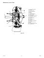
1
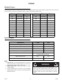
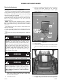
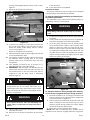
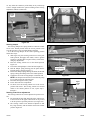
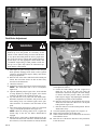
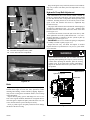
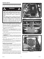
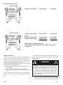
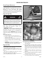
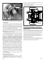
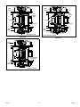
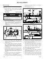
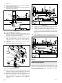
BigDog® Mowers Diablo® MP General Service Manual 200 South Ridge Road Hesston, Kansas 67062 120125 REV B WARNING The engine exhaust from this product contains chemicals known to the state of California to cause cancer, birth defects or other reproductive harm. NOTICE OF REQUIREMENT OF SPARK ARRESTER MUFFLER This equipment may create sparks that can start fires around dry vegetation. California Public Resources Code Section 4442.6 provides that it is unlawful to use or operate an internal combustion engine on any forest-covered, brush-covered, or grass-covered land unless the engine is equipped with a spark arrester maintained in effective working order. A spark arrester is a device constructed of nonflammable materials specifically for the purpose of removing and retaining carbon and other flammable particles over 0.0232 of an inch in size from the exhaust flow of an internal combustion engine that uses hydrocarbon fuels or which is qualified and rated by the United States Forest Service. Other states or federal areas may have similar laws. The Operator Should Contact Local Fire Agencies For Laws or Regulations Relating to Fire Prevention Requirements. THIS EQUIPMENT DOES NOT HAVE A SPARK ARRESTER AND YOU SHOULD CONTACT YOUR AUTHORIZED DEALER FOR THE PURCHASE OF A SPARK ARRESTER. Inspect spark arrester daily; replace every 500 hours or as needed. The Engine Owner’s Manual provides information regarding the U.S. Environmental Protection Agency (EPA) and the California Emission Control Regulation of emission systems, maintenance and warranty. Keep Engine Owner’s Manual with your unit. Should the Engine Owner’s Manual become damaged or illegible, replace immediately. Replacements may be ordered per the information found in the Product Information section of the owner’s manual. Federal law and California State law prohibit the following acts or the causing thereof: 1. The removal or rendering inoperative by any person other than for purposes of maintenance, repair, replacement, of any device or element of design incorporated into any equipment for the purposes of emissions control prior to or after its sales or delivery to the ultimate purchaser or while it is in use, or 2. The use of the equipment after such device or element of design has been removed or rendered inoperative by any person. REV B 120125 Table of Contents General Information . . . . . . . . . . . . . . . . . . . . . . . . . . . . . . . . . . . . . 1-1 BigDog® Mower Service Program. . . . . . . . . . . . . . . . . . . . . . . . 1-1 Maintenance Introduction . . . . . . . . . . . . . . . . . . . . . . . . . . . . . . 1-1 Warranty. . . . . . . . . . . . . . . . . . . . . . . . . . . . . . . . . . . . . . . . . . . 1-1 Safety. . . . . . . . . . . . . . . . . . . . . . . . . . . . . . . . . . . . . . . . . . . . . . . . 2-1 Safe Servicing Practices . . . . . . . . . . . . . . . . . . . . . . . . . . . . . . Understand Correct Service . . . . . . . . . . . . . . . . . . . . . . . . . . . . Pre-Operation Precautions. . . . . . . . . . . . . . . . . . . . . . . . . . . . . Operation Precautions . . . . . . . . . . . . . . . . . . . . . . . . . . . . . . . . Operate Machine Safely. . . . . . . . . . . . . . . . . . . . . . . . . . . . . . . General Maintenance Precautions . . . . . . . . . . . . . . . . . . . . . . . Maintenance Precautions. . . . . . . . . . . . . . . . . . . . . . . . . . . . . . 2-1 2-1 2-1 2-2 2-2 2-2 2-2 Torque . . . . . . . . . . . . . . . . . . . . . . . . . . . . . . . . . . . . . . . . . . . . . . . 3-1 Standard Torques. . . . . . . . . . . . . . . . . . . . . . . . . . . . . . . . . . . . 3-1 Special Torques . . . . . . . . . . . . . . . . . . . . . . . . . . . . . . . . . . . . . 3-1 Power Unit Maintenance . . . . . . . . . . . . . . . . . . . . . . . . . . . . . . . . . 4-1 Steering Adjustments . . . . . . . . . . . . . . . . . . . . . . . . . . . . . . . . . Park Brake Adjustment . . . . . . . . . . . . . . . . . . . . . . . . . . . . . . . Belts . . . . . . . . . . . . . . . . . . . . . . . . . . . . . . . . . . . . . . . . . . . . . . Hydraulic Pump Belt Adjustment . . . . . . . . . . . . . . . . . . . . . . . . Hydraulic System . . . . . . . . . . . . . . . . . . . . . . . . . . . . . . . . . . . . Tires . . . . . . . . . . . . . . . . . . . . . . . . . . . . . . . . . . . . . . . . . . . . . . 4-1 4-4 4-5 4-5 4-6 4-9 Engine Maintenance . . . . . . . . . . . . . . . . . . . . . . . . . . . . . . . . . . . . 5-1 General Engine Maintenance. . . . . . . . . . . . . . . . . . . . . . . . . . . Engine Oil And Filter . . . . . . . . . . . . . . . . . . . . . . . . . . . . . . . . . Engine Air Filter . . . . . . . . . . . . . . . . . . . . . . . . . . . . . . . . . . . . . Fuel & Evaporative System Line Routings . . . . . . . . . . . . . . . . . 5-1 5-1 5-1 5-2 Deck Adjustments . . . . . . . . . . . . . . . . . . . . . . . . . . . . . . . . . . . . . . 6-1 Deck Leveling. . . . . . . . . . . . . . . . . . . . . . . . . . . . . . . . . . . . . . . Blades . . . . . . . . . . . . . . . . . . . . . . . . . . . . . . . . . . . . . . . . . . . . Belts . . . . . . . . . . . . . . . . . . . . . . . . . . . . . . . . . . . . . . . . . . . . . . Deck Belt Adjustment . . . . . . . . . . . . . . . . . . . . . . . . . . . . . . . . . 60” & 72” Deck Belt Routing & Tensioning. . . . . . . . . . . . . . . . . 120125 toc-1 6-1 6-2 6-4 6-4 6-5 REV B Electrical . . . . . . . . . . . . . . . . . . . . . . . . . . . . . . . . . . . . . . . . . . . . . . 7-1 Electrical Schematic – Kawasaki . . . . . . . . . . . . . . . . . . . . . . . . . 7-1 Maintenance schedule . . . . . . . . . . . . . . . . . . . . . . . . . . . . . . . . . . . 8-1 Troubleshooting . . . . . . . . . . . . . . . . . . . . . . . . . . . . . . . . . . . . . . . . 9-1 REV B toc-2 120125 GENERAL INFORMATION BigDog® Mower Service Program This manual is part of a service package for the BigDog® Diablo® MP mowers. Use of this manual in conjunction with other BigDog® mower and component manuals will provide the information necessary to service and maintain BigDog® Diablo® MP mowers. This General Service Manual is a service guide for use by Service Technicians. It provides the necessary information needed to perform normal maintenance requirements on these units. The Parts Manual provides a complete parts listing for the unit. Use this manual when ordering parts. The Operator's Manual provides fundamental operational information and operational safety that is needed when operating the mower. The component manuals are furnished by the various manufacturers to be used for the troubleshooting and servicing of their components. Maintenance Introduction Regular maintenance is the best prevention for downtime or premature failure. The following pages contain suggested maintenance information and schedules which the operator/ mechanic should follow on a routine basis. Remain alert for unusual noises, they could be signaling a problem. Visually inspect the machine for any abnormal wear or damage. A good time to detect potential problems is while performing scheduled maintenance service. Correcting the problem as quickly as possible is the best insurance. Clear away heavy build-up of grease, oil and dirt, especially in the engine compartment and under the seat platform areas; 120125 1-1 minute dust particles are abrasive to close-tolerance engine and hydraulic assemblies. Daily inspect mower for grass clippings and wire and string tangles. The underside of the mower deck will collect a build-up of grass clippings and dirt, especially when grass is wet or has high moisture content. This build-up will harden, restricting blade and air movement and will probably show a lesser quality of cut. Therefore it should be removed routinely. To do this it will be necessary to raise and block the deck, using jack stands or blocks, in the full up position and scrape the build-up from underneath. Some repairs require the assistance of a trained service mechanic and should not be attempted by unskilled personnel. Consult your BigDog® Mowers service center when assistance is needed. Information included in this manual was current at the time of printing, but subsequent production changes may cause your machine to vary slightly in detail. BigDog® Mowers reserves the right to redesign and change the machine as deemed necessary, without notification. If a change has been made to your machine which is not reflected in this service manual contact the Customer Service Department at BigDog® Mowers for additional information. Warranty Warranty repair must be performed by a BigDog® Mowers Authorized Dealer before warranty credit can be allowed. Work performed by anyone other than an Authorized Dealer will invalidate the warranty claim and warranty credit will not be approved. REV B REV B 1-2 120125 SAFETY This safety alert symbol is used to call attention to a message intended to provide a reasonable degree of PERSONAL SAFETY for operators and other persons during the normal operation and servicing of this equipment. DANGER – denotes immediate hazards which WILL result in severe personal injury or death. WARNING – denotes a hazard or unsafe practice which COULD result in severe personal injury or death. Safe Servicing Practices This product is capable of amputating hands and feet and throwing objects. Always follow all safety instructions to avoid serious injury or death. Understand Correct Service Be sure you understand a service procedure before you work on the machine. Unauthorized modifications to the machine may impair the function and/or safety and affect machine life. If it is necessary to make checks with the engine running, always use two people - with the operator at the controls, able to see the person doing the checking. Pre-Operation Precautions Fuel Handling To avoid personal injury or property damage, use extreme care in handling fuel. Fuel is extremely flammable and the vapors are explosive. Observe usual fuel handling precautions: • Do not smoke while refueling. Extinguish all cigarettes, cigars, pipes and other sources of ignition. • Do not remove fuel cap or fill tank with engine running or while engine is hot. Clean up any fuel spills. • Allow engine to cool before storing machine inside a building. • Keep fuel away from open flame or spark and store machine away from open flame or spark or pilot light such as on a water heater or appliances. • Use extreme care when handling gasoline and other fuels. They are extremely flammable and vapors are 120125 2-1 explosive. A fire or explosion from fuel can burn you and others and can damage property. • Refuel outdoors. Never refuel or drain the fuel from the machine indoors. • Never attempt to start engine when there is a strong odor of gasoline or diesel fuel fumes present. Locate and correct cause. • Store fuel in an approved container and keep it out of the reach of children. Never buy more than a 30 day supply of fuel. • Do not fill fuel containers inside a vehicle or on a truck or trailer bed with interior carpets or plastic truck bed liners. Always place fuel containers on the ground away from your vehicle before filling. • When practical, remove gas or diesel fuel powered equipment from the truck or trailer and refuel the equipment with its wheels on the ground. If this is not possible, then refuel such equipment on the truck or trailer using a portable container and not a fuel dispenser nozzle. If a fuel dispenser nozzle must be used, keep the nozzle in contact with the rim of the fuel tank or container opening at all times until fueling is complete. Do not use a nozzle lock-open device. • Never use gasoline or diesel fuel for cleaning parts. • Read and observe safety precautions elsewhere in this manual. Gasoline and diesel fuel is harmful or fatal if swallowed. • Long-term exposure to vapors can cause serious injury and illness. • Avoid prolonged breathing of vapors. • Keep face away from nozzle and gas tank or fuel container opening. • Keep fuel away from eyes and skin. • If fuel is spilled on clothing, change clothing immediately. Understand Machine Operation Only qualified and trained personnel should operate the equipment. Carefully read the operator’s manual and all manuals furnished with the attachments. Learn the location and purpose of all controls, instruments, indicators and labels. Wear Protective Clothing Do not operate or service the equipment while wearing sandals, tennis shoes, sneakers, shorts or any type of loose fitting clothing. Long hair, loose clothing or jewelry may get tangled in moving parts. Always wear long pants, safety glasses, ear protection and safety shoes when operating or servicing this machine. Always wear adequate eye protection when servicing the hydraulic system and battery, or when grinding mower blades and removing accumulated debris. Prolonged exposure to loud noise can cause impairment or loss of hearing. • Always wear adequate ear protection, such as earplugs, when operating this equipment as prolonged exposure REV B to uncomfortable or loud noises can cause impairment or loss of hearing. • Do not wear radios or music headphones while operating the machinery. Safe operation requires your full attention. Operation Precautions Avoid Fire Hazards Clean flammable material from machine. Prevent fires by keeping engine compartment, top of deck, exhaust area, battery, hydraulic lines, fuel line, fuel tank and operator’s station clean of accumulated trash, grass clippings, and other debris. Always clean up spilled fuel and oil. Start Engine Safely Avoid possible injury or death from machine runaway. Do not start engine by shorting across starter terminals. Before you start the engine: • Sit on the operator’s seat. • Move control levers to the neutral/brake position. Operate Machine Safely Refer to the unit’s operator’s manual for complete safety information on safe machine operation. Always maintain a safe distance from people and pets when mowing Always be aware of what is behind the machine before backing up. Never leave machine unattended with ignition key in switch, especially with children present. Follow daily and weekly checklists, making sure hoses are tightly secured and bolts are tightened. Always keep engine and machine clean, removing accumulated dirt, trash and other material from machine. Never put hands or feet under any part of the machine while it is running. Never attempt to start engine when there is a strong odor of gasoline fumes present. Locate and correct cause. Keep all safety shields and covers in place, except for servicing. Do not touch hot parts of machine. General Maintenance Precautions Maintenance Precautions Repairs or maintenance requiring engine power should be performed by trained maintenance personnel only. Never run the engine in an enclosed area unless exhaust is vented to the outside. Exhaust gases contain carbon monoxide which is an odorless and deadly poison. Unless specifically required, DO NOT have engine running when servicing or making adjustments to mower. Park the machine on level ground. Place steering control levers in the park brake position, disengage deck clutch, lower deck, remove ignition switch key and disconnect negative battery cable before doing any maintenance. Wait for all movement to stop before adjusting, cleaning or repairing. To prevent carbon monoxide poisoning, be REV B sure proper ventilation is available when engine must be operated in an enclosed area. Before working on or under the deck, make certain engine cannot be accidentally started. Shut engine off, remove ignition switch key and disconnect negative battery cable for maximum safety. Except when changing or checking belt, always keep belt covers on mower deck for safety as well as cleanliness. Use a stick or similar instrument to clean under the mower making sure that no part of the body, especially arms and hands are under mower. Keep your machine clean and remove any deposits of trash and clippings, which can cause engine fires and hydraulic overheating as well as excessive belt wear. Clean up oil or fuel spillage. Allow machine to cool before storing. Always wear adequate eye protection when servicing the hydraulic system and battery, or when grinding mower blades and removing accumulated debris. Never attempt to make any adjustments or repairs to the mower drive system, mower deck or any attachment while the engine is running or deck clutch is engaged. Exercise caution when releasing spring tension from any of the belt idlers or when working with any of the deck lift components. Never work under the machine or attachment unless it is safely supported with jack stands. Make certain machine is secure when it is raised and placed on the jack stands. The jack stands should not allow the machine to move when the engine is running and the drive wheels are rotating. Use only certified jack stands. Use only appropriate jack stands, with a minimum weight rating of 2000 pounds to block the unit up. Use in pairs only. Follow the instructions supplied with the vehicle stands. Keep nuts and bolts tight, especially the blade attachment bolts. Keep equipment in good working condition. Never tamper with safety devices. Check their proper operation regularly. Exercise caution when working under the deck as the mower blades are extremely sharp. Wrap the blade(s) or wear gloves and use extra caution when servicing them. Use only genuine BigDog® Mower replacement parts to ensure that original standards are maintained. 2-2 Avoid Fire Hazards Be prepared if an accident or fire should occur. Know where the first aid kit and the fire extinguishers are located and how to use them. Provide adequate ventilation when charging batteries. Do not smoke near battery. Never check fuel level with an open flame. Never use an open flame to look for leaks anywhere on the equipment. Never use an open flame as light anywhere on or around the equipment. When preparing engine for storage, remember that fuel stabilizer is volatile and therefore dangerous. Seal and 120125 tape openings after adding the inhibitor. Keep container tightly closed when not in use. Inspect electrical wiring for worn or frayed insulation. Install new wiring if wires are damaged. Prepare For Emergencies Be prepared if a fire starts. Keep a first aid kit and fire extinguishers available. Keep emergency numbers for doctor, ambulance service, hospital, and fire department near the telephone. Prevent Battery Explosions Battery posts, terminals, and related accessories contain lead and lead compounds, chemicals known to the State of California to cause cancer and reproductive harm. Wash hands after handling. Charge batteries in an open well-ventilated area, away from sparks and flames. Unplug charger before connecting or disconnecting from battery. Wear protective clothing and use insulated tools. Avoid skin and clothing contact with battery acid. • Always wear eye protection when checking the battery, acid can cause serious injury to skin and eyes. If contact occurs, flush area with clean water and call physician immediately. Acid will also damage clothing. • Do not drink the battery electrolyte. • Do not allow open flame near the battery when charging. • Hydrogen gas forms inside the battery. This gas is both toxic and flammable and may cause an explosion if exposed to flame. Always disconnect the negative (black) battery cable(s) before disconnecting the positive (red) cable(s). Always connect the positive (red) battery cable(s) before connecting the negative (black) cable(s). • Do not overfill battery. • Electrolyte may overflow and damage paint, wiring or structure. When cleaning the battery, use soap and water. Be careful not to get soap and water into the battery. Clean the battery terminals with a solution of four 120125 2-3 parts water and one part baking soda when they become corroded. Shorts caused by battery terminals or metal tools touching metal mower components can cause sparks. Sparks can cause a battery gas explosion which will result in personal injury. • Prevent the battery terminals from touching any metal mower parts when removing or installing the battery. • Do not allow metal tools to short between the battery terminals and metal mower parts. Incorrect battery cable routing could cause damage to the mower and battery cables. This can cause sparks which can cause a battery gas explosion which will result in personal injury. Always disconnect the negative (black) battery cable(s) before disconnecting the positive (red) cable(s). Always connect the positive (red) battery cable(s) before connecting the negative (black) cable(s). Avoid Acid Burns Sulfuric acid in battery electrolyte is poisonous. It is strong enough to burn skin, eat holes in clothing and cause blindness if splashed in eyes. Avoid the hazard by: • Filling batteries in a well-ventilated area. • Wearing eye protection and rubber gloves. • Avoiding breathing fumes when electrolyte is added. • Avoiding spilling or dripped electrolyte. If you spill acid on yourself: • Flush your skin with water. • Apply baking soda or lime to help neutralize the acid. • Flush your eyes with water for 10-15 minutes. Get medical attention immediately. If acid is swallowed: • Drink large amounts of water or milk. • Then drink milk of magnesia, beaten eggs or vegetable oil. • Get medical attention immediately. REV B REV B 2-4 120125 TORQUE Standard Torques The following chart lists the standard torque values for the threaded fasteners found in this manual. Torque all cap screws, nuts and set screws to these values unless a different torque is shown in the Special Torques section. SIZE FT-LBS N-M SIZE FT-LBS N-M #10 32.4 IN.-LBS. 3.6 M3 12 IN.-LBS. 1.3 .250 98.4 IN.-LBS. 11.1 M4 26.4 IN.-LBS. 3 .312 204 IN.-LBS. 23 M5 54 IN.-LBS. 6.1 .375 30 40 M6 92.4 IN.-LBS. 10.4 .438 48 65 M8 222 IN.-LBS. 25 .500 73 99 M10 37 50 .562 105 143 M12 64 87 .625 145 200 M14 103 140 .750 260 350 M16 160 215 .875 420 565 M20 320 435 Special Torques DESCRIPTION FT-LBS N-M Wheel (lug) nuts 1 70 95 Blade spindle bolt top 70 95 Blade spindle bolt bottom 118 160 Electric clutch mounting bolt 3 45 – 48 61 – 65 Front wheel axle bolt Tighten the nut, then back it off until the wheel spins freely Wheel motor hub nut 230 312 Hydraulic pump pulley screw 14 19 NOTE: 1. Lug nuts only – It is recommended that these be checked after the first 2 hours of operation and every 50 hours and following removal for repair or replacement. 2. Engine torque values – Refer to the respective engine owner’s manual. 3. If clutch mounting bolt is loosened or removed, do not re-use. Replace with a new bolt. Use only hand tools to install this fastener. 120125 3-1 WARNING Particular attention must be given to tightening the drive wheel lug nuts and blade spindle bolts. Failure to correctly torque these items may result in the loss of a wheel or blade, which can cause serious damage or personal injury. REV B REV B 3-2 120125 POWER UNIT MAINTENANCE Steering Adjustments Steering control lever neutral adjustment The mower’s steering has been factory adjusted to eliminate creeping when the steering control levers are in the neutral position. However, should the mower begin to creep, the steering control lever linkage can be adjusted. Before considering any adjustment, check the tire air pressure. Unequal tire pressure will cause the mower to drift to one side. Refer to tire pressure information in the Tires section for detailed information. NOTE: Proper park brake adjustment must be completed before the steering control lever neutral adjustment can be done. Refer to the Park Brake Spring Adjustment section for detailed information. Fine adjustment to the unit’s steering is made with the transmission’s control rod. Neutral is properly adjusted when the steering control levers are in the park brake position and the transmissions do not “whine”. If this occurs, the steering control linkage may be adjusted as follows: 3. Raise the seat platform and disconnect the mower harness from the seat switch. Bypass the seat switch by connecting the two mower harness female spades together. Figure 4-1 Seat switch Female spades Female spades Mower harness WARNING This procedure will require that the unit be raised and blocked up off of the ground. It is necessary for the wheels to rotate without coming in contact with the floor or any object that would permit the unit to propel itself. Stay clear and exercise caution when rotating wheels to prevent injury. Use only appropriate vehicle stands, with a minimum weight rating of 2000 pounds to block the unit up. Use in pairs only. Follow the instructions supplied with the vehicle stands. Figure 4-1 4. Start the engine. 5. Position the steering control lever in the neutral position and observe which way the wheels are rotating. Figure 42 Steering control lever in neutral position WARNING Keep hands, hair, clothing, etc., clear of the cooling fans on top of the transmissions. Exercise extreme caution. WARNING Untrained maintenance personnel should never attempt to make any adjustments or repairs to the mower’s drive system while the engine is running. The following procedures should be performed by trained maintenance personnel only. 1. Raise the rear of the mower and block with certified jack stands. The rear wheels need to be able to rotate freely and clear of all obstructions. 2. Chock the front tires. 120125 4-1 Figure 4-2 6. If wheel(s) are rotating forward, loosen the jam nuts on the pump linkage rods and rotate the rod to lengthen the REV B steering control linkage until the wheel(s) come to a stop. Figure 4-3 7. Repeat for the opposite side if necessary. Jam nut Lower the mower. 15. Lower and secure the seat platform. Control lever stops The steering control lever stops (see Figure 4-4) are designed to keep the pumps from bottoming out internally. To keep the pumps from bottoming out internally use the following procedure: This adjustment is only required if the hydraulic pump(s) or pump linkage rod(s) have been replaced. WARNING Pump damage will occur if these stops are set incorrectly. Pump linkage rod Figure 4-3 8. If wheel(s) are rotating in reverse then loosen the jam nuts on the pump linkage rods and rotate the rod to shorten the steering control linkage until the wheel(s) come to a stop. Figure 4-3 Repeat for the opposite side if necessary 9. When both wheels remain in neutral, tighten the jam nuts to lock the turnbuckle in place. 10. Test again by moving the steering control levers forward and backward before returning them to the neutral position. If the tires are in neutral, the unit is now ready for operation. 11. After adjusting for neutral it may be necessary to readjust the control lever stop and/or damper. 12. IMPORTANT: With the engine off, disconnect the two female spade connectors from each other (from step #3) and reconnect them to the seat switch. This must be completed so that the safety circuit is functioning properly. Figure 4-1 1. To make the first adjustment the mower engine must not be running. 2. Check to make sure the pump stop screws are against the stops before the pumps are bottomed out internally. 3. To do this, gently and slowly move the steering control levers forward and feel if there is some resistance on the pump lever before the pump stop screws hit the stops. Check one side at a time. If you sense that the pump arms are stopping the forward motion of the control arms, turn the pump stop screw, of the corresponding side, inward to stop the steering control levers slightly before the pump bottoms out. Do this for each side. Pump stop screw WARNING Steering damper Do not operate the mower without plugging the mower’s wiring harness into the seat switch. This switch is an important part of the safety start interlock system. Serious injury can result if the seat switch is not plugged into the mower’s wiring harness. Figure 4-4 WARNING Never operate the mower with a non-functioning seat switch. Always reconnect the seat switch to the mower harness. 13. Check to make sure all tools or obstructions are removed from under the mower. 14. Raise the rear of the mower and remove the jack stands. REV B 4-2 To adjust the stops for driving straight when steering control levers are against the stops during operation: 1. Determine which drive tire is rotating too fast when both steering control levers are against the drive straight stops in the control panel (see Figure 4-5). 2. Then, stop the mower and loosen the lock nut on the side which is rotating too fast and turn the stop (set screw) inward to stop the steering control lever sooner. Tighten the lock nut on the stop and test again. 3. Repeat this procedure until unit drives straight. NOTE: Since this is a hydrostatic drive, variables such as temperature of oil, efficiency of pumps and motors, tire pressure 120125 etc. may effect the consistency of the ability to rely on the stops to drive straight without the operator making minor steering adjustments with the control arms. Steering control lever Steering control lever in neutral position Jam nut Drive straight stop Figure 4-5 Figure 4-6 Steering damper The steering dampers are spring loaded to return the control levers to the neutral position from the reverse position. This gives the operator a sense of neutral during operation. To set the steering dampers in the correct operating position follow these steps: 1. Shut engine off, place steering control levers in the park brake position, disengage deck clutch, remove ignition switch key and disconnect negative battery cable before doing any adjustments. 2. Place the steering control lever in the neutral position. Figure 4-6 3. Loosen the steering damper’s front ball stud. Figure 4-7 4. Pull the damper spring housing past the point that the internal spring is engaged. Figure 4-7 5. Release the damper spring housing and allow the internal spring to bring the housing back to the neutral position. 6. Tighten the nut on the steering damper’s front ball stud. NOTE: The damper must not bottom out when the pump lever is fully stroked in either direction. 7. Reconnect the negative battery cable. 8. Lower and secure the seat platform. 9. To check, move the steering control lever to the reverse position and release. The steering control lever should return to the neutral position. If not, repeat steps 1 through 6. Steering control lever adjustment The steering control levers can be adjusted for operator comfort. 1. By loosening the nuts that attach the upper control lever to the lower lever the upper control lever can be pivoted to fit the operator’s personal preference (see Figure 4-8) 2. The steering control levers should be adjusted so that they align vertically with each other when in the neutral position. Figure 4-9 Rear ball stud Steering damper spring housing Figure 4-7 Upper control lever Nuts Lower control lever Figure 4-8 120125 4-3 REV B Align handles ± .125” Brake link Figure 4-9 Park Brake Adjustment Figure 4-10 WARNING This procedure will require that the unit be raised and blocked up off of the ground. It is necessary for the wheels to rotate without coming in contact with the floor or any object that would permit the unit to propel itself. Stay clear and exercise caution when rotating wheels to prevent injury. Use only appropriate vehicle stands, with a minimum weight rating of 2000 pounds to block the unit up. Use in pairs only. Follow the instructions supplied with the vehicle stands. Bypass valve 1. Shut engine off, place steering control levers in the park brake position, disengage deck clutch, remove ignition switch key and disconnect negative battery cable before doing any adjustments. 2. Raise the rear of the mower and block with certified jack stands. The rear wheels need to be able to rotate freely and clear of all obstructions. 3. Chock the front tires. 4. Position the steering control levers in the neutral position. NOTE: The front brake link is not to be adjusted. Figure 4-10 5. Open the hydraulic pump’s bypass valve, on the side that is being adjusted, by turning the bypass valve counter clockwise one-half to one revolution. Figure 4-11 6. Try and rotate the tire by hand. The tire should rotate. Remember hydraulic oil resistance will prevent the tire from rotating freely even with the bypass valves open. There should be no resistance from the brakes at this point. 7. Move the steering control lever to where it is just inside (1/8” [3.175mm]) the park brake slot. Figure 4-12 NOTE: When the steering control lever is against the outside edge of the slot, the brakes should not be engaged. 8. Rotate the tire. If the brake is adjusted properly the tire will still rotate but friction will start to become noticeable here. However, if no brake resistance is noticed, the brake REV B 4-4 Figure 4-11 9. 10. 11. 12. needs adjusted as follows: a. Loosen the brake linkage jam nuts. (Figure 4-13) Rotate the tire and at the same time rotate the turnbuckle to shorten the length of the brake linkage to increase the brake pressure. When you feel the brake begin to engage, stop adjusting the turnbuckle. Re-tighten the jam nuts on the turnbuckle. b. Place the control lever in the park brake slot. The tire should not rotate when the control lever is in the park brake position. Figure 4-12 c. Place the control lever in the neutral position. The tire should rotate freely. Close the hydraulic pump’s bypass valve. Figure 4-11 Repeat steps 4 through 9 for the other side. Check to make sure all tools or obstructions are removed from under the mower. Raise the rear of the mower and remove the jack stands. Lower the mower. 120125 Keep oil and grease away from belts, and never use belt dressings. Any of these will destroy the belt composition in a very short time. Hydraulic Pump Belt Adjustment The transmission drive belt tension remains constant by means of a tension idler and spring. The spring tension should be such that the belt does not slip under normal operating load conditions, assuming the belt is not excessively worn or damaged. As the belt stretches and wears in, adjustment may become necessary. The proper belt tension is achieved when the tension spring is stretched to a dimension of 8.0” – 8.5” (203 – 216mm) when measured from the inside of the hook to the inside of the other hook. Figure 4-14 To increase belt tension, loosen the jam nut on the eye bolt. Then, tighten the nut on the eyebolt until the 8.0” - 8.5” (203 – 216mm) dimension is attained. Lock the eyebolt in place by tightening the jam nut. Figure 4-14 IMPORTANT: Do not over tension the spring to compensate for a badly worn belt or pulley. Figure 4-14 Inspect the belt every 100 hours and replace as needed. Replace the belt every 400 hours or every two (2) years whichever comes first. Control lever Park brake slot Outside edge 1/8” (3.175mm) Figure 4-12 13. Reconnect the negative battery cable. 14. Lower and secure the seat platform. WARNING If the transmission belt fails, loss of control will occur especially when operating on a slope. If you lose steering control while operating the machine, place the steering control levers in the park brake position immediately. Inspect the machine and involve your dealer to resolve the problem. Bottom View Hydraulic pump belt Jam nuts Tension idler Figure 4-13 Belts Inspect belts frequently for wear and serviceability. Replace a belt that shows signs of severe cuts, tears, separation, weather checking and cracking, or burns caused by slipping. Slight raveling of belt covering does not indicate failure, trim ravelings with a sharp knife. Inspect the belt pulley grooves and flanges for wear. A new belt, or one in good condition, should never run against the bottom of the groove. Replace the pulley when this is the case, otherwise, the belt will lose power and slip excessively. Never pry a belt to get it on a pulley as this will cut or damage the fibers of the belt covering. 120125 4-5 Spring Figure 4-14 REV B Hydraulic System IMPORTANT: Never use hydraulic or automatic transmission fluid in this system; use only motor oil as specified. Remember, dirt is the primary enemy of any hydraulic system. WARNING Hydraulic reservoir Hydraulic fluid escaping under pressure may have sufficient force to penetrate skin and cause serious injury. Foreign fluid injected into the skin must be surgically removed within a few hours by a doctor, familiar with this form of injury, or gangrene may result. Before applying pressure to hydraulic system, make sure all connections are tight and all hoses and lines are in good condition. To find a leak under pressure, use a piece of cardboard or wood — never use your hands. Relieve all pressure in the system before disconnecting or working on hydraulic lines. To relieve pressure, lower all attachments and shut off engine. Figure 4-15 Check oil level in hydraulic system after every 50 hours of operation or weekly, whichever occurs first. Check more often if system appears to be leaking or otherwise malfunctioning. Fluid level should be 1” (2.54cm) from top of reservoir. (Figure 4-15) Use only SAE 20W50 SL/SM service motor oil for the BigDog® Diablo® MP mowers. NOTE: The reservoir will require approximately 3.0 U.S. gallons (11.35 liters) of SAE 20W50 SL/SM service motor oil when replacing the oil after an oil and filter change. Do not overfill the reservoir. Change hydraulic system filter element and oil after first 50 hours of mower operation, then replace filter and oil in reservoir every 500 hours thereafter. IMPORTANT: It is necessary to drain the system oil from the hydraulic reservoir, using the reservoir drain plug, before removing the hydraulic filter. Replace the drain plug before adding system oil. Use a 15/16” socket for the hydraulic system filter. The threads are right hand. Figure 4-16 The hydraulic system filter is located inside the hydraulic reservoir on the underneath side of the tank. Use a BigDog® Mowers approved filter element only. Figure 4-16 Hydraulic filter Hydraulic reservoir Figure 4-16 Hydraulic oil heat exchanger The BigDog® Diablo® MP mower is equipped with a hydraulic oil heat exchanger. The heat exchanger coils must be kept clean to insure that the hydraulic oil is operating within the correct temperature range. Check and clean the heat exchanger daily and more often in dirty, dusty conditions. Figure 4-17 Hydraulic Pump Flow Test The design purpose of the Bi-Directional Flow Test Kit is to allow the technician to isolate the pump from the wheel motor and determine if the pump is acceptable. The following information can be used to install and test the pump by simulating a REV B 4-6 Heat exchanger Figure 4-17 wheel motor load. 120125 WARNING WARNING Never work under the machine or attachment unless it is safely supported with jack stands. Make certain machine is secure when it is raised and placed on the jack stands. The jack stands should not allow the machine to move when the engine is running and the drive wheels are rotating. Use only certified jack stands. Use only appropriate jack stands, with a minimum weight rating of 2000 pounds to block the unit up. Use in pairs only. Follow the instructions supplied with the vehicle stands. Certain procedures require the vehicle engine to be operated and the vehicle to be raised off of the ground. To prevent possible injury to the servicing technician and/or bystanders, insure the vehicle is properly secured. WARNING Do not attempt any adjustments with the engine running. Use extreme caution while working in or around all vehicle linkage! High temperatures can be generated. Follow all safety procedures outlined in the vehicle owner’s manual! 4. Installation & Testing Procedures Disconnect the system hoses at the wheel motor, or system hoses from the pump and connect the Bi-Directional Flow Test Kit. (Special care should be taken to prevent contamination debris from entering pump or wheel motor system ports). NOTE: Using the Bi-Directional Flow Test Kit, determination of directional flow is not necessary. The flow meter may be connected in either direction into the forward and reverse high pressure system lines. NOTE: The following adapter fittings will be required when connecting the Bi-Directional Test Kit (Excel P/N 783886 or Hydro-Gear P/N 70661): PY (21) Series Pumps require two 771311 adapter fittings. CAUTION: Ensure all fittings and hoses are attached securely. This test is being completed on the vehicle’s high pressure system lines. Failure to perform this properly could result in bodily injury. Testing Procedures 1. Use approved jack stands to raise the drive wheels off the floor. 2. Open the restriction valve all the way. 3. For the pump being tested, move the steering control 120125 4-7 5. 6. 7. 8. levers in full forward motion. (It will be necessary to lock the steering control levers into full forward position to prevent false readings). Increase the engine rpms until a maximum of 15 gpm shows on the Flow Test Kit gauge. CAUTION: Damage to the flow meter and/or recalibration may result from testing at input speeds that exceed the above recommendations. Operate without any load for approximately 30 seconds to 1 minute. This allows the system oil temperature to rise. NOTE: Raising the system oil temperature will make a difference in the readings you receive. It has been determined that to complete this test accurately, the oil temperature must be near system operating temperatures. Suggested temperature range 160° - 210° F (71.1° - 98.9° C) Tighten the flow meter restriction valve until the gauge reads 300 psi (21 bar). Record the flow reading on the Bi-Directional Flow Meter. Increase the pressure to 1100 PSI (76 bar). Record the flow reading on the Bi-Directional Flow Meter. The acceptable gpm “flow droop” or (difference) is: PY (21) 2.5 gpm (9.4 l/min) If the difference exceeds these values the pump would not be operating efficiently and should be replaced or repaired. See the following example. REV B Test Example: PY (12) Pump RESTRICTION VALVE BI-DIRECTIONAL FLOW METER 300 psi (21 bar) reading 7 gpm (26 l/min) (1st reading) 1100 psi (76 bar) reading 3 gpm (11 l/min) (2nd reading) 7 gpm (26 l/min) -3 gpm (11 l/min) 4 gpm (15 l/min) (1st reading) (2nd reading) (the difference) CONNECTIONS TO THE FWD/RVS LINES DISCONNECTED FROM WHEEL MOTOR RESTRICTION VALVE BI-DIRECTIONAL FLOW METER CONNECTIONS TO THE FWD/RVS LINES DISCONNECTED FROM WHEEL MOTOR PK (12) 300 psi (21 bar) reading 1100 psi (76 bar) reading Subtract the 1st reading from the 2nd. (In this example, 4 gpm difference would indicate further pump examination). Purging Procedures Due to the affects air has on efficiency in hydrostatic drive applications, it is critical that air is purged from the system. These purge procedures should be implemented any time a hydrostatic system has been opened to facilitate maintenance or additional oil has been added to the system. Air creates inefficiency because its compression and expansion rates that are higher than that of oil. Entrained air in the oil may cause the following symptoms: 1. Noisy operation. 2. Lack of power or drive after short term operation. 3. High operation temperature and excessive expansion of oil. Before starting, make sure the reservoir is at the proper oil level. If it is not, fill to the vehicle manufacturer’s specifications. The following procedures should be performed with the vehicle drive wheels off the ground, then repeated under normal operating conditions. WARNING Potential for serious injury! Certain procedures require the vehicle be operated and the vehicle to be raised off of the ground. To prevent possible injury to the servicing technician and/or bystanders, insure the vehicle is properly secured. Use only appropriate vehicle stands, with a maximum weight rating of 2000 pounds to block the unit up. Use in pairs only. Follow the instructions supplied with the vehicle stands. 1. With the bypass valve open and the engine running, slowly move the directional control in both forward and reverse directions (5 or 6 times), as air is purged from the REV B 4-8 120125 unit, the oil level will drop. 2. With the bypass valve closed and the engine running, slowly move the directional control in both forward and reverse directions (5 or 6 times). Check the oil level and add oil as required after stopping the engine. It may be necessary to repeat Steps 1 and 2 until all the air is completely purged from the system. When the pumps operate smoothly forward and reverse at normal speeds, purging is complete. 120125 4-9 Tires It is important for level mowing that the tires have the same amount of air pressure. The recommended pressures are: Drive wheels . . . . . . . . . . . . . . . . . . . . . 8-12 psi (55-83 KPa) Front wheels . . . . . . . . . . . . . . . . . . . . . 8-12 psi (55-83 KPa) If you wish to use non-pneumatic tires on your BigDog® mower the tires must be an approved tire purchased from BigDog® Mowers. Warranty claims will be denied on any mower equipped with unapproved non-pneumatic tires. REV B REV B 4-10 120125 ENGINE MAINTENANCE General Engine Maintenance Detailed instructions and recommendations for break-in and regular maintenance are specified in the Engine Owner’s Manual. Please refer to this manual for engine servicing, lubricating oil levels with quality and viscosity recommendations, bolt torques, etc. The engine warranty is backed by the manufacturer. Special attention should be paid to applicable data which will not be duplicated here. Oil drain valve Engine Oil And Filter WARNING If the engine has been running and is up to operating temperature, allow the engine to cool before changing the oil. Engine and engine oil will be very hot, so be very careful when changing oil and wear the appropriate protective gear to avoid being burned or exposed to engine oil. Figure 5-1 Pre-cleaner Check engine oil daily and after every 4 hours of operation. Machine must be setting level when checking oil. Refer to engine manual and maintenance schedule for oil recommendation and capacities. IMPORTANT: Change the engine oil and filter after the first 5 hours of operation and per the engine manufacturer’s recommendations after that. If mower is being operated in extremely dirty conditions, then it is recommended oil be changed more frequently. IMPORTANT: When removing the oil filter take precautions to minimize oil spillage on the exhaust system. Draining the engine oil: 1. Locate the oil drain valve on the engine. Figure 5-1 2. Position a suitable oil drain container under the machine below the oil drain valve. 3. Twist the valve counterclockwise to open the valve. Allow 10 minutes for engine oil to adequately drain. 4. After oil is drained, close the valve by twisting it clockwise. 5. Once the valve is closed, clean up any spilled oil. IMPORTANT: All oil drips or spills must be cleaned off of the exhaust system before operating the machine. Engine Air Filter Perform engine air filter maintenance per the Maintenance Schedule shown elsewhere in this manual. A specially designed dry filter is standard equipment on these mowers and supplies clean combustion air to the engine. Figure 5-2 These mowers are equipped with a safety filter. The filter element slides over the safety filter. Figure 5-3 The safety element does not require servicing unless it becomes contaminated with dirt or moisture. 120125 5-1 Canister Dust cap Figure 5-2 Recommended service procedure 1. Release clamps and remove element. Clean the canister with a damp cloth. 2. Before installing a new element, inspect it by placing a bright light inside and rotating the element slowly, looking for any holes or tears in the paper. Also check gaskets for cuts or tears. Do not attempt to use a damaged element which will allow abrasive particles to enter the engine. 3. Reinstall the dust cap. Make sure it seals all the way around the air cleaner body, then tighten the clamps. Figure 5-2 4. Check all fittings and clamps periodically for tightness and inspect hoses for holes or cracks. 5. Periodically check the intake hose for signs of ingested dust. Locate and repair the source of ingested dirt. REV B 9xxxxxEX (i.e. 922222AU or 922222EX) model number do not have a fuel evaporation system filter. This filter must be replaced every 500 hours or annually whichever comes first.Figure 5-4 Safety filter Figure 5-3 6. Never operate the machine without an air filter installed. Overservicing Overservicing occurs when an air filter element is removed for cleaning or replacement before it is necessary. Each time the filter is removed a small amount of dirt and dust could fall in the intake system. This accumulated dirt can cause a dusted engine. It only takes a few grams of ingested dirt over the normal service life of an engine to cause a dusted engine. Do not clean the element, but replace with a new element only. Cleaning used air filter elements, through improper cleaning procedures, can get dust on the inside of the filter causing dirt ingestion and engine failure. It is important to note that whenever an air filter element is cleaned by any method, the person or company performing the cleaning assumes responsibility for the integrity of the filter from then on. The warranty for air filters expires upon cleaning or servicing in any manner because the condition of the filter after servicing is completely out of the filter manufacturer’s control. Therefore, on a dust ingested engine failure, there will be no warranty consideration if the air filter element has been cleaned or serviced in any manner. A partially dirty air filter element works better than a new element. Therefore, a dirty filter element is not bad for the engine unless it is excessively restricting the air flow and engine performance is affected. The reason is simple. The media in the filter must be porous to allow air to pass through it. When dirty air passes through the filter, the dirt plugs some of the holes in the media and actually acts as part of the filter media. When the next round of dirt enters, the first dirt helps filter out even smaller particles making the filter more efficient at stopping dirt from entering the engine. This is referred to as barrier filtration. Of course, at some point the filter media becomes too clogged to allow air to pass. The mowing conditions will determine the frequency of air filter element changing. Fuel evaporation system filter Figure 5-4 Fuel & Evaporative System Line Routings Domestic mowers There are two rubber hoses that are connected to the fuel tanks. One is the fuel hose that is part of the fuel system. The other is the vapor line that is part of the fuel evaporative system. The fuel hose is connected to the rear port on the fuel tank. It connects the fuel tank to the fuel shutoff valve. Figure 5-5 The vapor line is connected to the front port of the fuel tank. It connects the fuel tank to the engine’s vapor port. Figure 5-6 Export (EX or AU) mowers These mowers will have the fuel line only. The fuel hose is connected to the side port on the fuel tank. NOTE: There is no vapor line installed on these mowers. Figure 5-7 Fuel Evaporation System Filter All BigDog® Diablo® MP mowers with a 9xxxxx (i.e. 922222) model number, have a fuel evaporation system filter. Figure 5-4 BigDog® Diablo® MP mowers with a 9xxxxxAU or REV B 5-2 120125 Fuel tank Fuel tank Fuel shutoff valve Fuel shutoff valve Fuel line Fuel line Seat support Seat support Fuel tank Fuel tank Domestic mowers Export (EX or AU) mowers Figure 5-5 Figure 5-7 Fuel tank Tee Vapor line Fuel evaporation system filter Fuel tank Domestic mowers Figure 5-6 120125 5-3 REV B Engine RPM Settings The engine rpm’s are set at the factory for maximum mowing efficiency. Occasionally it may be necessary to check and adjust the settings. The high idle speeds, with no load, should be set as follows: Kawasaki FX850 & FX1000 ENGINE SPEED MODEL NO. ENDING WITH: HIGH IDLE MODEL NO. WITHOUT EXTENSION MODEL NO. WITH EX EXTENSION MODEL NO. WITH AU EXTENSION 3600 RPM NOTE: Model numbers may or may not end with an extension after the number. There are several different extensions that may be shown; i.e. EX or CE. Example: 922222 (no extension) 922222 EX 922222 CE 922222 US 922222 AU REV B 5-4 120125 DECK ADJUSTMENTS Deck Leveling Leveling the deck must be done in the following manner and order: 1. Check tire pressures to make certain they are properly inflated before starting to level deck. The recommended pressures are as follows: Drive wheels . . . . . . . . . . . . . . . . . 8-12 psi (55-83 KPa) Gauge wheels . . . . . . . . . . . . . . . . . 8-12 psi (55-83 KPa) from the lift block at approximately 1" (2.54cm) (left & right side). Figure 6-4 10. Jam both nuts against the block. Clamp here Stop handle WARNING Stop engine. Make sure deck clutch switch is in the down (OFF) position. Place control levers in the brake position before leaving machine. Deck adjustment stop 2. Park the unit on a flat surface. 3. Place 3” high deck support blocks (two stacked 2” x 4” blocks can be used to create a 3” [7.62cm] high support) at the four corners of the deck as shown. Figure 6-1 NOTE: Back of deck will automatically be set 1/4” (6.35mm) higher. Block Nuts Block Foot pedal Block Block Figure 6-3 Figure 6-1 4. Place the height stop in the 3” hole, with the plate side of the height adjusting stop against the stop handle for a cut height setting of 3.25”. 5. Clamp the height adjusting stop against the stop handle. This will assure that the height will not move during the setting process. Otherwise, spring pressure from the deck lift springs will tend to pull the stop away from the handle. Figure 6-2 6. Loosen all nuts on the deck lift threaded rods, and the hardware on the height indicator bar (on the right front), until all the deck lift chains are loose, and the deck is sitting tightly on all four blocks. Figure 6-3, Figure 6-4 & Figure 6-7 7. Loosen the two nuts on the front of height indicator so that the foot pedal is free. Figure 6-3 & Figure 6-7 8. Start the leveling process on the left front of the mower. 9. Set the amount of threads protruding on the deck lift rod 120125 Figure 6-2 6-1 11. Push or pull on the deck lift foot pedal until the chain on the left front just becomes tight, making sure that the deck stays tight against the block. 12. While keeping the chain tight, tighten the nuts against the deck lift block on the height indicator rod, just enough to carry most of the deck weight on that side — the block should be able to move with only a slight drag. Figure 64 13. Jam nuts tightly together against the deck lift block. 14. Go to the right front of the mower. 15. Loosen the 5/16” jam nut on the adjuster lift chain, and back the adjuster bolt out to allow the adjuster to move up and down freely. Figure 6-5 16. Tighten the adjuster bolt until the chain just becomes tight. Then tighten just enough to carry the weight of the front of the deck on that side—to check, move the blocks back and forth; they should move with a slight drag. REV B Figure 6-5 17. Tighten the adjuster bolt jam nut to prevent the adjuster bolt from moving. Figure 6-5 18. Tighten the hardware holding the chain and adjuster onto the deck lift arm. Figure 6-5 Lift block Nuts 1” Chains 1” Deck lift rod Figure 6-4 19. Go to the right rear of the mower. 20. Make sure that there is still slack in the chain. If not, loosen the two nuts on the block holding the threaded rod until there is slack in the deck lift chain. 21. Tighten the appropriate nut until the chain just becomes tight, and carries most of the deck weight. Check by moving the block—it should move with a slight drag. Figure 6-6 22. Tighten the other nut on the opposite side of the block, and jam them tightly together against the block. Figure 6-6 26. Tighten the other nut on the opposite side of the block, and jam them tightly together against the block. 27. Compress the deck lift assist springs so that there is 1” (25.4mm) of space between the front nut on the spring and the rear nut on the deck lift block. Typical both sides. Figure 6-4 28. When completed, all chains will be tight, and deck cutting height will be set to the deck height indicator. Nut Nut Deck lift threaded rod 5/16” bolt Chains Adjuster Hardware Jam nut Figure 6-7 Blades Figure 6-5 23. Go to the left rear of the mower. 24. Make sure that there is still slack in the chain. If not, loosen the two nuts on the block holding the threaded rod until there is slack in the deck lift chain. Figure 6-7 25. Tighten the appropriate nut until the chain just becomes tight, and carries most of the deck weight. Check by moving the block—it should move with a slight drag. Figure 6-7 REV B 6-2 Mower blade maintenance Check the mower blades daily, they are the key to power efficiency and well groomed turf. Keep the blades sharp. A dull blade will tear rather than cut the grass, leaving a brown ragged top on the grass within a few hours. A dull blade also requires more power from the engine. 120125 IMPORTANT: When mounting blades, rotate them after installation to ensure blade tips do not touch each other or sides of the mower. Replace any blade which is bent, cracked or broken. WARNING WARNING Never attempt to straighten a bent blade by heating, or weld a cracked or broken blade as the blade may break and cause serious injury. Replace worn or damaged blades. Failure to correctly torque the bolt may result in the loss of the blade which can cause serious injury. WARNING WARNING Never work with blades while engine is running or deck clutch switch is engaged (on). Always place deck clutch switch in the disengaged position, place steering control levers in the park brake position and turn engine off and disconnect negative battery cable. Block up mower when you must work under it. Wear gloves when handling blades. Always check for blade damage if mower strikes a rock, branch or other foreign object during mowing! Mower blades are sharp and can cut. Wrap the blade(s) or wear gloves and use extra caution when servicing them. Resharpening pattern WARNING Always wear adequate eye protection when grinding mower blades. Mower blade removal Use a 15/16” wrench to remove the 5/8” cap screw holding the blade to the spindle shaft from underneath. NOTE: A blade holding tool (part number 381442) is available from BigDog® Mowers. It is designed to prevent the blades from rotating when they are being removed or installed on the spindle. Contact your BigDog® Mowers dealer for more information. Sharpen the blades on a grinder following pattern as shown (Figure 6-8). Touch-up sharpening can be done with a file Check the blades for balance following grinding. A commercial balancing tool is available through most hardware supply stores, or balancing can be done by placing the blade on an inverted line punch or 5/8” bolt. Blade should not lean or tilt. Spin the blade slowly, blade should not wobble. If blade is out of balance, true it up before reinstalling. Lay the blade on a flat surface and check for distortion (Figure 6-9 & Figure 6-10). Replace any distorted blade. Do not re-use spindle bolts which have stripped, worn or undercut threads. Torque bolts on spindles to 118 foot-pounds (160.0 N-m) when reinstalling blades. Properly compressed cup washers maintain the correct compression load on the blades. Replace the cup washers if they are cracked or flattened. IMPORTANT: The blade sail (curved part) must be pointing upward toward the inside of the deck to ensure proper cutting. 120125 6-3 Do not sharpen to original pattern (below). It is easier to get a straight cutting edge following the resharpening pattern shown above. Original edge Figure 6-8 Warped Blade (Replace) Cutting plane Straight Blade Comparison of Warped and Straight Blades Figure 6-9 REV B IMPORTANT: Do not over tension the spring to compensate for a badly worn belt or pulley. Cutting edge Twisted Blade Edge (replace) Cutting Plane Spring chain Spring chain anchor point Cutting edge Straight Blade Edge End view of blades, comparing twisted and straightened blades Figure 6-10 Idler spring Belts Inspect belts frequently for wear and serviceability. Replace a belt that shows signs of severe cuts, tears, separation, weather checking and cracking, or burns caused by slipping. Slight raveling of belt covering does not indicate failure, trim ravelings with a sharp knife. Inspect the belt pulley grooves and flanges for wear. A new belt, or one in good condition, should never run against the bottom of the groove. Replace the pulley when this is the case, otherwise, the belt will lose power and slip excessively. Never pry a belt to get it on a pulley as this will cut or damage the fibers of the belt covering. Keep oil and grease away from belts, and never use belt dressings. Any of these will destroy the belt composition in a very short time. Figure 6-11 Deck Belt Adjustment The spindle belt tension remains constant by means of a tension idler and spring. The spring tension should be such that the belt does not slip under normal operating load conditions, assuming the belt is not excessively worn or damaged. As the belt stretches and wears in, adjustment may become necessary. To increase belt tension, move the spring chain one (or more) link(s) at the anchor point on the deck frame. Figure 6-11 REV B 6-4 120125 NOTE: The following notes are the same for the two different decks shown. 1. Spring length after tensioning new belt. Measured from outside of hook to outside of hook with deck set at 3¼” (8.26cm) cut height. 2. Route belt as shown. 60” & 72” Deck Belt Routing & Tensioning 9.3” – 10.3” (236 – 262 mm) Figure 6-12 120125 6-5 REV B REV B 6-6 120125 ELECTRICAL Electrical Schematic – Kawasaki 120125 7-1 REV B REV B 7-2 120125 MAINTENANCE SCHEDULE Maintenance Schedule Refer to Figure 8-1, Figure 8-2, & Figure 8-3 WEEKLY OR 40 HOURS SERVICE AT INTERVALS INDICATED MONTHLY OR 100 HOURS ANNUALLY OR 500 HOURS Verify safety start interlock system Prior to each use Visually inspect unit for loose hardware and/or damaged parts Prior to each use Visually inspect tires Prior to each use Check oil level, engine (1)(4) Prior to each use or every 4 hours Clean air intake screen (7) Prior to each use or every 4 hours Check fuel level Prior to each use Blades - sharpen & securely fastened Prior to each use Discharge chute - securely in place & in lowest position Prior to each use Clean engine and pump compartment Daily Grease deck pusher arms X Grease pump idler X Grease deck height pivots X Grease front wheel bearings X Check battery connections X Check tire pressure with a gauge X Check hydraulic oil level X Clean engine exterior (A) X Check pump and deck belt tension and condition (5) X Check fuel system (6)(7) X Check hydraulic lines X Tighten lug nuts on wheels (2) X Change fuel filter (6) X Clean or replace hydraulic fill cap X Change hydraulic filter & oil (3) X Grease deck spindle housings X Check ROPS mounting hardware (8) X Replace fuel evaporation system filter (6)(7) X NOTES: 1. 2. 3. 4. 5. 6. 7. 8. Initial oil change is after 5 hours of operation. Thereafter, change oil after every 40 hours operation. Change more often under dusty or dirty conditions and during hot weather periods. Torque initially and after first 2 hours of operation. Perform initial hydraulic oil and filter change after 50 hours (one week) of operation. Change engine oil filter per the engine manufacturer’s recommendations. Refer to Engine Owner’s Manual for recommendations and other maintenance items. Pump drive belt only - Inspect every 100 hours and replace if worn or cracking is noticed. Otherwise, replace every 400 hours or 2 years whichever comes first. Check fuel system for any cracks or leaks including but not limited to fuel line hoses, fuel valve, vent line hoses, vent valve, vapor valve, carbon canister and grommets. Replace as needed. More often under dusty or dirty conditions and during hot weather. Inspect ROPS after the first 20 hours of operation and then after every 500 hours of operation or yearly whichever comes first. REFERENCES: A. Refer to Engine Owner’s Manual NOTE: Refer to engine owner’s manual for engine service information. NOTE: After completing maintenance cycle (500 hours), repeat cycle. 120125 8-1 REV B Maintenance Locator Chart 7 6 9 2 12 11 21 3 10 4 1 21 12 11 6 5 9 20 Figure 8-1 1. 2. 3. 4. 5. 6. 7. 8. 9. 10. 11. 12. 13. 14. 15. 16. 17. 18. 19. 20. 21. 13 15 8 14 Engine Oil Fill & Dipstick Fuel Filter Engine Air Cleaner Engine Oil Drain Valve Battery Fuel Tanks Hydraulic Oil Reservoir Hydraulic Oil Filter Front Wheel Bearing Zerks (2) Engine Oil Filter Deck Height Pivot Zerks (4) Park Brake Switch Drive Tire Pump Idler Zerk (1) Pump Belt Deck Pusher Arm Zerks (2) Deck Belt Spindle Housing Zerk (3) Blades Fuel evaporation system filter Front Wheel Tires 13 Figure 8-2 REV B 8-2 120125 Maintenance Locator Chart 19 18 16 19 17 18 18 16 1. 2. 3. 4. 5. 6. 7. 8. 9. 10. 11. 12. 13. 14. 15. 16. 17. 18. 19. 20. 21. Engine Oil Fill & Dipstick Fuel Filter Engine Air Cleaner Engine Oil Drain Valve Battery Fuel Tanks Hydraulic Oil Reservoir Hydraulic Oil Filter Front Wheel Bearing Zerks (2) Engine Oil Filter Deck Height Pivot Zerks (4) Park Brake Switch Drive Tire Pump Idler Zerk (1) Pump Belt Deck Pusher Arm Zerks (2) Deck Belt Spindle Housing Zerk (3) Blades Fuel evaporation system filter Front Wheel Tires 19 Figure 8-3 120125 8-3 REV B REV B 8-4 120125 TROUBLESHOOTING SYMPTOMS SYMPTOMS Starting motor does not crank The engine will not start, starts hard or fails to keep running Engine: Runs with continuous misfiring or engine runs unevenly or erratically PROBABLE CAUSES Steering control levers not in park brake position or switch not adjusted Place steering control levers in park brake position or re-adjust switch Deck clutch switch engaged Disengage clutch switch Weak or dead battery Recharge or replace Electrical connections are corroded or loose Check the electrical connections For additional causes See engine manual No fuel or line plugged Fill tank or replace line (See Fuel System section for more details) Fuel valve is turned off Open the fuel valve There is incorrect fuel in the fuel system Drain the tank and replace the fuel with the proper type There is dirt in the fuel filter Replace the fuel filter Dirt, water or stale fuel in the fuel system Contact your Dealer The choke is not on Move the choke lever to ON Mower jerky when starting or operates in one direction only Hydraulic system operates hot (oil in reservoir smells rancid) Mower creeps when steering control levers are in neutral Mower circles or veers in one direction Mower creeps when parking brake engaged Low engine oil pressure High oil consumption 120125 Steering control linkage needs adjustment Adjust linkage Pump or wheel motors faulty Contact your Dealer Tow valves not closed completely Close tow valves Low hydraulic oil level Fill reservoir Hydraulic pump faulty Contact your Dealer Hydraulic oil cooler clogged Clean oil cooler core Steering linkage needs adjustment Adjust linkage Steering linkage needs adjustment Adjust linkage Wheel motors faulty Contact your Dealer Tires improperly inflated Adjust air pressure to 8 - 12 psi (55-83 KPa) Hydraulic pump faulty Contact your Dealer Steering linkage out of adjustment Adjust steering linkage See engine manual Brakes need adjustment Adjust parking brakes Numerous See engine manual The engine mounting bolts are loose Tighten the engine mounting bolts The engine pulley, idler pulley or blade pulley is loose Tighten the appropriate pulley Restrictions in air cleaner Service air cleaner Contact your Dealer The engine is pulley is damaged Contact your Dealer Hydraulic line blockage Internal interference or leakage in wheel motor Contact your Dealer The cutting blade(s) is/are bent or unbalanced Install new cutting blade(s) A blade mounting bolt is loose Tighten the blade mounting bolt Spindle bearing is worn or loose Replace or tighten spindle bearing A blade spindle is bent Contact your Dealer The deck drive belt is worn, loose or broken Install a new deck drive belt The deck drive belt is off the pulley Install the deck drive belt and check for a reason Electric clutch is not engaging Check and/or replace 20 amp fuse. Contact your Dealer The blade(s) are not sharp Sharpen the blades A cutting blade(s) is/are bent Install new cutting blade(s) The deck is not level Level the deck per the Deck leveling and height adjustment section of the parts manual An anti-scalp wheel is not set correctly Adjust the height of the anti-scalp wheel The underside of the deck is dirty Clean the underside of the deck Tires improperly inflated Adjust air pressure to 8 - 12 psi (55-83 KPa) A blade spindle is bent Contact your Dealer There is abnormal vibration Check level in reservoir Air cooled engine overheating SUGGESTED REMEDIES Numerous Insufficient hydraulic oil supply Loss of power or system will not operate in either direction PROBABLE CAUSES SUGGESTED REMEDIES Have dealer check hydraulic pump Poor compression Contact your Dealer Steering linkage needs adjustment Adjust linkage Tow valve open Close tow valve The traction drive belt is worn, loose or broken Install a new traction drive belt Air in system Check filter and fittings Blades do not rotate For additional causes See engine manual Air intake screen or cleaning fins clogged Clean screen and fin For additional causes See engine manual Low oil level Add oil Oil diluted or too light Change oil and check for source of contamination Failed oil pump Contact your Dealer Numerous Contact your Dealer Uneven cutting height 9-1 REV B REV B 9-2 120125 INDEX PAGE PAGE Belts . . . . . . . . . . . . . . . . . . . . . . . . . . . . . . . . . .4-5, 6-4 Maintenance Precautions . . . . . . . . . . . . . . . . . . . . 2-2 Blades . . . . . . . . . . . . . . . . . . . . . . . . . . . . . . . . . . . 6-2 Maintenance Schedule . . . . . . . . . . . . . . . . . . . . . . 8-1 Control lever stops . . . . . . . . . . . . . . . . . . . . . . . . . . 4-2 Mower blade maintenance . . . . . . . . . . . . . . . . . . . . 6-2 Deck Belt adjustment . . . . . . . . . . . . . . . . . . . . . . . . 6-4 Mower blade removal . . . . . . . . . . . . . . . . . . . . . . . 6-3 Deck Belt Routing & Tensioning . . . . . . . . . . . . . . . . 6-5 Operate Machine Safely . . . . . . . . . . . . . . . . . . . . . 2-2 Deck leveling . . . . . . . . . . . . . . . . . . . . . . . . . . . . . . 6-1 Operation Precautions . . . . . . . . . . . . . . . . . . . . . . . 2-2 Electrical Schematic – Kawasaki . . . . . . . . . . . . . . . 7-1 Park brake adjustment . . . . . . . . . . . . . . . . . . . . . . . 4-4 Engine air filter . . . . . . . . . . . . . . . . . . . . . . . . . . . . . 5-1 Pre-Operation Precautions . . . . . . . . . . . . . . . . . . . 2-1 Engine oil and filter . . . . . . . . . . . . . . . . . . . . . . . . . . 5-1 Purging Procedures . . . . . . . . . . . . . . . . . . . . . . . . . 4-8 Engine RPM settings . . . . . . . . . . . . . . . . . . . . . . . . 5-4 Safe servicing practices . . . . . . . . . . . . . . . . . . . . . . 2-1 Fuel & evaporative system line routings . . . . . . . . . . 5-2 Service Program . . . . . . . . . . . . . . . . . . . . . . . . . . . 1-1 Fuel evaporation system filter . . . . . . . . . . . . . . . . . . 5-2 Special torques . . . . . . . . . . . . . . . . . . . . . . . . . . . . 3-1 General engine maintenance . . . . . . . . . . . . . . . . . . 5-1 Standard torques . . . . . . . . . . . . . . . . . . . . . . . . . . . 3-1 General Maintenance Precautions . . . . . . . . . . . . . . 2-2 Steering adjustments . . . . . . . . . . . . . . . . . . . . . . . . 4-1 Hydraulic oil heat exchanger . . . . . . . . . . . . . . . . . . 4-6 Steering control lever adjustment . . . . . . . . . . . . . . 4-3 Hydraulic pump belt adjustment . . . . . . . . . . . . . . . . 4-5 Steering control lever neutral adjustment . . . . . . . . 4-1 Hydraulic Pump Flow Test . . . . . . . . . . . . . . . . . . . . 4-6 Steering damper . . . . . . . . . . . . . . . . . . . . . . . . . . . 4-3 Hydraulic system . . . . . . . . . . . . . . . . . . . . . . . . . . . 4-6 Tires . . . . . . . . . . . . . . . . . . . . . . . . . . . . . . . . . . . . . 4-9 Maintenance introduction . . . . . . . . . . . . . . . . . . . . . 1-1 Understand Correct Service . . . . . . . . . . . . . . . . . . 2-1 Maintenance Locator Chart . . . . . . . . . . . . . . . .8-2, 8-3 Warranty . . . . . . . . . . . . . . . . . . . . . . . . . . . . . . . . . 1-1 120125 i-1 REV B