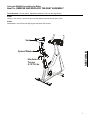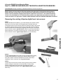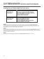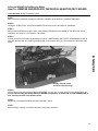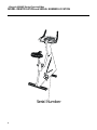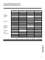
1
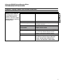
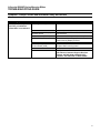
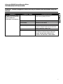
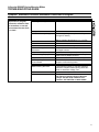
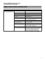
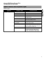
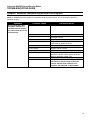
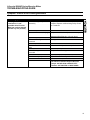
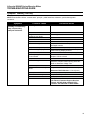
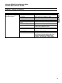
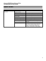
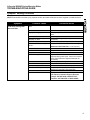
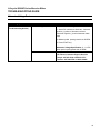
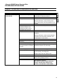
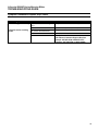
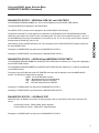
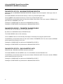
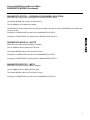
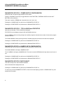
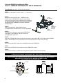
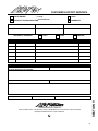
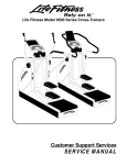
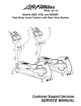
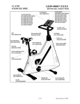
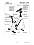
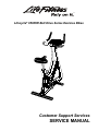
TM Lifecycle 9500HR Belt Drive Series Exercise Bikes Customer Support Services SERVICE MANUAL Lifecycle 9500HR Series Exercise Bikes INTRODUCTION HOW TO USE SERVICE MANUAL AND CONTACT CUSTOMER SUPPORT SERVICES This service manual is applicable to Lifecycle Model 9500HR (via Lifepulse digital and Polar compatible telemetry heart rate monitoring systems) belt-drive exercise bikes. Information is appropriate to all models unless otherwise noted. Note: Information represents typical configuration and may differ slightly from actual equipment. The Service Manual provides recommendations of safe and efficient approaches to problem situations. This manual is separated into five sections. INTRODUCTION THEORY OF OPERATION TABLE OF CONTENTS Section I TROUBLESHOOTING GUIDES Section II DIAGNOSTIC MODE Section III "How To..." SERVICE AND REPAIR GUIDES Section IV PARTS IDENTIFICATION WIRING BLOCK DIAGRAMS Section V MISCELLANEOUS INFORMATION Refer to TABLE OF CONTENTS for section topics. When an operating problem occurs, refer to trouble shooting guides and diagnostic mode to isolate cause . When applicable, guides are listed by problem symptom followed with suggestions of probable cause(s) . Once source of problem is identified, consult "How To..." guides for recommended repair procedures. "How To..." sub-sections are organized by replaceable part or assembly name. For convenience, sub-section lists recommended “Tools Required” to complete specific function. Refer to PARTS IDENTIFICATION to identify proper name and number of part to order for repair of equipment. A reproducible FAX order claim form is given in COMMUNICATING BY TELEFACSIMILE for convenient ordering of service parts. To order, contact Life Fitness Customer Support Services. Via FAX - 24 hrs. /day, 7 days/week. Via telephone - Monday through Friday from 8:00 AM to 6:00 PM ( CST). Via post - At address cited. To speed Life Fitness Customer Support Services response to your needs, please provide the following information. 1. Model number 2. Serial number 3. Symptom of problem 4. Part name and number to order (if known) Before installing part, review "How To..." and follow step by step procedures recommended to install part safely and efficiently. Lifecycle 9500HR Series Exercise Bikes THEORY OF OPERATION The Lifecycles bikes are stationary exercise bicycles that provide a scientific method of improving body fitness and endurance through its unique “12 or 24 MINUTE RIDE TO VIGOROUS HEALTH.” Computerized state-of-the-art electronics have been engineered to satisfy a range of personalized fitness needs of the beginner to the needs of the most advanced fitness enthusiast. The Lifecycle concept is based on the self-motivational principle of INTERVAL TRAINING WITH PROGRESSIVE OVERLOAD. During the HILL and RANDOM exercise programs, the workload against which you are pedaling is periodically changed by the built-in computer resulting in an automatic increase or decrease in pedal resistance. This simulates riding up and down virtual “hills,” which are visualized on the display console with columns of “lights” that move from right to left. With features like the RACE program, Fit Test, level 0 resistance - almost 25% easier than the level 1 found on earlier editions of the classic Lifecycle exercise bike - and exciting variable-ergonomic handlebars, you’ll be much more likely to stick with your exercise plan and accomplish your goals. The ability to select a program to match your particular needs is what distinguishes Lifecycle bikes as the world’s most popular physical conditioning device. Its user-flexibility means that you will never outgrow the innumerable challenges the Lifecycle exercise bike has to offer. The beginner starts with basic programs, then improves his level of fitness at his own rate while constantly challenging himself to the next level. For well-conditioned individuals, the advanced programs offer more difficult modes of training. In fact, many world-class athletes use Lifecycle bikes to maintain peak levels of conditioning. The Lifecycle bike is an extremely rugged exercise bicycle that is designed to withstand heavy use for many years. During its two-year research and development phase, prototype Lifecycles were placed in high-volume health clubs and fitness centers across the United States where they were field tested for up to 18 hours a day. If you have questions or comments please telephone, FAX or, write us. We are: LIFE FITNESS - CUSTOMER SUPPORT SERVICES 10601 Belmont Avenue; Franklin Park, IL 60131; U.S.A. Telephone: 847.451.0036...........Toll-free: 800.351.3737 FAX: 847.288.3702.....................Toll-free: 800.216.8893 Lifecycle 9500HR Series Exercise Bikes TABLE OF CONTENTS INTRODUCTION How to use this Service Manual Theory of Operation SECTION I TROUBLESHOOTING GUIDES PAGE NO POWER .......................................................................................................................... 2 DISPLAY CONSOLE INITIALIZES THEN FAILS ................................................................ 3 ERRATIC DISPLAY CONSOLE L.E.D.S.............................................................................. 4 DISPLAY CONSOLE L.E.D.S REMAIN ILLUMINATED ...................................................... 5 PROMPT PERSISTS AND INFORMATION ENTRY NOT ALLOWED................................ 6 PROMPT EXTINGUISHES WHEN START KEY IS RELEASED AND INFORMATION ENTRY NOT ALLOWED .................................................................. 7 DISPLAY CONSOLE KEYS DO NOT FUNCTION .............................................................. 8 IMMEDIATE, EXCESSIVE RESISTANCE LOAD AT START OF PROGRAM ................... 9 EXCESSIVE RESISTANCE LOAD DURING PROGRAM .................................................... 10 RESISTANCE VARIES DURING MANUAL PROGRAM...................................................... 11 RESISTANCE CONSTANT DURING RANDOM OR HILL PROGRAMS ............................ 12 DIFFICULT OR NO PEDALING MOVEMENT ..................................................................... 13 PEDALING TOO EASY ........................................................................................................ 14 BATTERY OVER-HEATING ................................................................................................. 15 NOT STABLE ....................................................................................................................... 16 EMITTING LOAD NOISE...................................................................................................... 17 ALTERNATOR VOLTAGE TEST ......................................................................................... 18 NO HEART RATE OR DISPLAY READS NO HEART RATE .............................................. 19 HANDLEBAR/LIFEPULSE GRIPS LOOSE ......................................................................... 20 SECTION II DIAGNOSTIC MODES DIAGNOSTICS STATE – HOW TO ENTER……………………………………………………..2 DIAGNOSTICS STATE – OVERVIEW……………………………………………………………3 DIAGNOSTICS STATE 1 - ALL LEDS and KEYPAD TEST ................................................4 ALL LED TEST KEYPAD TEST SPEAKER TEST DIAGNOSTICS STATE 2 - INDIVIDUAL LED TEST ............................................................4 INDIVIDUAL LED TEST DIAGNOSTICS STATE 3 - VERSION #: RPM, HR, and LOAD TESTS...............................5 PROGRAM VERSION NUMBER PEDAL RPM HEART RATE LOAD DUTY CYCLE CONTROL DIAGNOSTICS STATE 4 - LIFEPULSE and NETWORK STATUS TESTS ........................5 LIFEPULSE HC05 and DSP PROGRAM VERSION.REVISION #s LIFE LINK CONNECTION STATUS DIAGNOSTICS STATE 5 - LOOPBACK TESTS ..................................................................5 LOOPBACK TEST FOR CVA COMMUNICATIONS DIAGNOSTICS STATE 6 - MAXIMUM PROGRAM DURATION ..........................................6 MAXIMUM PROGRAM TIME DIAGNOSTICS STATE 7 - TELEMETRY ENABLE/DISABLE .............................................6 TELEMETRY ENABLE/DISABLE DIAGNOSTICS STATE 8 - ENGLISH/METRIC UNITS.........................................................6 ENGLISH UNITS/METRIC UNITS CONFIGURATION DIAGNOSTICS STATE 9 - UPRIGHT/RECUMBENT SELECTION .....................................7 LC9500 or LC9500R CONFIGURATION Lifecycle 9500HR Series Exercise Bikes TABLE OF CONTENTS (continued) DIAGNOSTICS STATE 10 - WATTS.....................................................................................7 WATTS ENABLED / DISABLED DIAGNOSTICS STATE 11 - METS .......................................................................................7 METS ENABLED / DISABLED STATISTICS (OPTIONAL) DIAGNOSTICS STATE 12 – POWER SUPPLY CONFIGURATION ....................................8 6-VOLT BATTERY / EXTERNAL POWER SUPPLY / 9-VOLT BATTERY / CVA DIAGNOSTICS STATE 13 – TOTAL HOURS AND STATISTICS ........................................8 TOTAL HOURS AND STATISTICS ARE SHOWN DIAGNOSTICS STATE 14 - NUMERIC KEYS CONFIGURATION…………………………..8 NUMERIC KEYS ENABLED / DISABLED DIAGNOSTICS STATE 15 – PHOTO SHOOT…………………………………………………..8 SOLELY USED FOR A PHOTO SHOOT SECTION III How To...REMOVE AND REPLACE… THE ALTERNATOR .......................................................................................................... 2 ALTERNATOR BELT ....................................................................................................... 3 DRIVE BELT...................................................................................................................... 4 CRANK ARM AND BEARINGS......................................................................................... 5,6 SEAT ASSEMBLY............................................................................................................. 7 MAIN WIRE HARNESS ..................................................................................................... 8,9 BATTERY .......................................................................................................................... 10 DISPLAY CONSOLE......................................................................................................... 11 ALTERNATOR CONTROL BOARD ................................................................................. 12 FOOT STRAP .................................................................................................................... 13 FRONT WHEELS .............................................................................................................. 14 HANDLEBAR ASSEMBLY................................................................................................ 15,16 DIGITAL HEART RATE SENSORS .................................................................................. 17,18 HEART RATE PC BOARD ................................................................................................ 19 HOUSING .......................................................................................................................... 20 PEDALS............................................................................................................................. 21 SEAT PLUNGER ............................................................................................................... 22 STABILIZER BAR ............................................................................................................. 23 TELEMETRY RECEIVER.................................................................................................. 24 SECTION IV WIRING BLOCK DIAGRAMS............................................................................................................ 2 PARTS LISTS .................................................................................................................................... 3-10 SECTION V MODEL IDENTIFICATION AND SERIAL NUMBER LOCATION ..................................................... 2 PREVENTATIVE MAINTAINENCE TIPS .......................................................................................... 3 COMMUNICATING BY FAX.............................................................................................................. 4 FAX FORM......................................................................................................................................... 5 MISCELLANEOUS NOTES............................................................................................................... 6 TM ©1999 Brunswick Corporation. All rights reserved. Life Fitness and Lifecycle are registered trademarks of Brunswick Corporation. Lifepulse, Zone Trainer and Heart Rate Zone Training are trademarks of Brunswick Corporation. Any use of these trademarks, without the express written consent of Brunswick Corporation, is forbidden. M051-00K46-A004 1/99 Lifecycle 9500HR Series Exercise Bikes SECTION I TROUBLESHOOTING GUIDES 1 Lifecycle 9500HR Series Exercise Bikes TROUBLESHOOTING GUIDE Symptom: No Power Symptom Display Console LEDs do not illuminate Probable Cause Corrective Action Pedaling too slowly Pedal faster than 45 RPM then press the START button. Keypad not responding Massage keypad with fingertips. Insufficient battery voltage Test the battery voltage. It should be: 5.8 to 6.3 VDC. If necessary, replace the battery with a fully charged 6V battery. Loose wire connections Disconnect then reconnect connections. Worn or damaged wire harnesses. Inspect wire harnesses. Replace worn or damaged harness. Malfunctioning Display Console Test with substitute Display Console. Replace malfunctioning Display Console. Malfunctioning Alternator Control Board (ACB) Test with substitute ACB. Replace malfunctioning ACB. Malfunctioning Alternator Test Alternator output or test with substitute Alternator. Replace malfunctioning Alternator. Refer to Alternator Voltage Test. For Assistance Contact: Life Fitness Customer Support Services 847.451.0036 or 800.351.3737 Telefacs.: 847.288.3702 or 800.216.8893 2 Lifecycle 9500HR Series Exercise Bikes TROUBLESHOOTING GUIDE Symptom: Display Console Initializes Then Fails Symptom Display Console initializes then fails Probable Cause Corrective Action Loose wire connections Disconnect then secure connections. Worn or damaged wire harnesses Inspect wire harnesses. Replace worn or damaged harness. Malfunctioning Display Console Test with substitute Display Console. Replace malfunctioning Display Console. Malfunctioning Alternator Control Board Test with substitute Alternator Control Board. Replace malfunctioning board. Malfunctioning Alternator Test Alternator output or, test with substitute Alternator. Replace malfunctioning Alternator. Refer to Alternator Voltage Test. For Assistance Contact Life Fitness Customer Support Services Teleph.: 847.451.0036 or 800.351.3737 Telefacs.: 847.288.3702 or 800.216.8893 3 Lifecycle 9500HR Series Exercise Bikes TROUBLESHOOTING GUIDE Symptom: Erratic Display Console LEDs Symptom Display Console LEDs are not constant Probable Cause Corrective Action Pedaling too slowly Pedal faster than 45 RPM. Insufficient battery voltage Test the battery voltage. It should be: 5.8 to 6.3 VDC. If necessary, replace the battery with a fully charged 6V battery. Loose wire connections Disconnect then reconnect connections. Worn or damaged wire harnesses Inspect wire harnesses. Replace worn or damaged harnesses. Malfunctioning Display Console Test with substitute Display Console. Replace malfunctioning Display Console. Malfunctioning Alternator Control Board Test with substitute Alternator Control Board. Replace malfunctioning board. Malfunctioning Alternator Test Alternator output or test with substitute Alternator. Replace malfunctioning Alternator. Refer to Alternator Voltage Test. For Assistance Contact Life Fitness Customer Support Services Teleph.: 847.451.0036 or 800.351.3737 Telefacs.: 847.288.3702 or 800.216.8893 4 Lifecycle 9500HR Series Exercise Bikes TROUBLESHOOTING GUIDE Symptom: Display Console LEDs Remain Illuminated Symptom Display Console LEDs do not extinguish in timely manner at the end of a workout , when the CLEAR key is pressed, or when the pedaling stops. Probable Cause Corrective Action Loose wire connections Disconnect then reconnect the connections. Worn or damaged harnesses Inspect wire harnesses. Replace worn or damaged harnesses. Malfunctioning Alternator Control Board Test with substitute Alternator Control Board. Replace defective board. Malfunctioning Display Console Inspect for damage or depression at START key. Test with substitute Display Console. Replace malfunctioning Display Console. For Assistance Contact Life Fitness Customer Support Services Teleph.: 847.451.0036 or 800.351.3737 Telefacs.: 847.288.3702 or 800.216.8893 5 Lifecycle 9500HR Series Exercise Bikes TROUBLESHOOTING GUIDE Symptom: Prompt Persists and Information Entry Not Allowed Symptom Prompt persistently flashes and entry of additional information is not allowed. Probable Cause Corrective Action Pedaling too slowly Pedal faster than 45 RPM. Attempting to enter improper duration of time Refer to Operation Manual for time duration requirements. Malfunctioning Display Console Test with substitute Display Console. Replace malfunctioning Display Console. Malfunctioning Alternator Control Board (ACB) Test with substitute Alternator Control Board. Replace Malfunctioning board. For Assistance Contact Life Fitness Customer Support Services Teleph.: 847.451.0036 or 800.351.3737 Telefacs.: 847.288.3702 or 800.216.8893 6 Lifecycle 9500HR Series Exercise Bikes TROUBLESHOOTING GUIDE Symptom: Prompt Extinguishes When Start Key Is Released and Information Entry Not Allowed Symptom Probable Cause Prompt extinguishes when START key is released and entry of additional information is not allowed. Malfunctioning Display Console Test with substitute Display Console. Replace malfunctioning Display Console. Corrective Action Malfunctioning Alternator Control Board Test with substitute ACB. Replace defective Alternator Control Board. Malfunctioning Alternator Test Alternator output or, test with substitute Alternator. Replace malfunctioning Alternator. Refer to Alternator Voltage Test. For Assistance Contact Life Fitness Customer Support Services Teleph.: 847.451.0036 or 800.351.3737 Telefacs.: 847.288.3702 or 800.216.8893 7 Lifecycle 9500HR Series Exercise Bikes TROUBLESHOOTING GUIDE Symptom: Display Console Keys Do Not Function Symptom Display Console keys (except START key) do not function and Exercise Bike does not respond. Probable Cause Corrective Action Attempting to enter program not available. Refer to Operation Manual for program availability. Keypad is cold Massage keypad with fingertips. Display Console connection loose Test with substitute Display Console. Replace malfunctioning Display Console. Malfunctioning Display Console Test with substitute Display Console. Replace malfunctioning Display Console. For Assistance Contact Life Fitness Customer Support Services Teleph.: 847.451.0036 or 800.351.3737 Telefacs.: 847.288.3702 or 800.216.8893 8 Lifecycle 9500HR Series Exercise Bikes TROUBLESHOOTING GUIDE Symptom: Immediate, Excessive Resistance Load at Start of Program Symptom Upon start of program, excessive resistance load is immediate; no normal, incremental increase from “no load.” Probable Cause Corrective Action Pedaling too slowly Pedal faster than 45 RPM. Insufficient battery voltage Test battery voltage or replace with fully charged 6V battery. Battery Voltage Specification: 5.8 - 6.3 VDC Loose wire connections Disconnect then, reconnect connections. Worn or damaged wire harnesses Inspect wire harnesses. Replace worn or damaged harness. Malfunctioning Display Console Test with substitute Display Console. Replace malfunctioning Display Console. Malfunctioning Alternator Control Board Test with substitute Alternator Control Board. Replace malfunctioning board. Malfunctioning Alternator Test Alternator output or, test with substitute Alternator. Replace malfunctioning Alternator. Refer to Alternator Voltage Test. For Assistance Contact Life Fitness Customer Support Services Teleph.: 847.451.0036 or 800.351.3737 Telefacs.: 847.288.3702 or 800.216.8893 9 Lifecycle 9500HR Series Exercise Bikes TROUBLESHOOTING GUIDE Symptom: Excessive Resistance Load During Program Symptom During program, excessive resistance loading occurs. Probable Cause Corrective Action Pedaling too slowly Pedal faster than 45 RPM. Loose wire connections Disconnect then, reconnect connections. Worn or damaged wire harnesses Inspect wire harnesses. Replace worn or damaged harness. Malfunctioning Display Console Test with substitute Display Console. Replace malfunctioning Display Console. Malfunctioning Alternator Control Board (ACB) Test with substitute ACB. Replace malfunctioning ACB. Malfunctioning Alternator Test Alternator output or, test with substitute Alternator. Replace malfunctioning Alternator. Refer to Alternator Voltage Test. For Assistance Contact Life Fitness Customer Support Services Teleph.: 847.451.0036 or 800.351.3737 Telefacs.: 847.288.3702 or 800.216.8893 10 Lifecycle 9500HR Series Exercise Bikes TROUBLESHOOTING GUIDE Symptom: Resistance Varies During Manual Program NOTE: In RANDOM and HILL programs, resistance variation may be normal. Test for resistance variation in MANUAL program. Symptom During MANUAL program, resistance variation occurs. Probable Cause Corrective Action Pedaling too slowly Pedal faster than 45 RPM. Loose wire connections Disconnect then, reconnect connections. Worn or damaged harnesses Inspect wire harnesses. Replace worn or damaged harness. Malfunctioning Display Console Test with substitute Display Console. Replace malfunctioning Display Console. Malfunctioning Alternator Control Board Test with substitute Alternator Control Board. Replace defective board. Malfunctioning Alternator Test Alternator output or, test with substitute Alternator. Replace malfunctioning Alternator. Refer to Alternator Voltage Test. For Assistance Contact Life Fitness Customer Support Services Teleph.: 847.451.0036 or 800.351.3737 Telefacs.: 847.288.3702 or 800.216.8893 11 Lifecycle 9500HR Series Exercise Bikes TROUBLESHOOTING GUIDE Symptom: Resistance Constant During Random or Hill Programs NOTE: In RANDOM and HILL programs, resistance variation may be normal. Test for resistance variation in MANUAL program. Symptom During RANDOM or HILL programs, resistance is constant without variation for interval training nor hill incline/decline. Probable Cause Corrective Action Loose wire connections Disconnect then, reconnect connections. Worn or damaged harnesses Inspect wire harnesses. Replace worn or damaged harness. Malfunctioning Display Console Test with substitute Display Console. Replace malfunctioning Display Console. Malfunctioning Alternator Control Board Test with substitute Alternator Control Board. Replace defective board. Malfunctioning Alternator Test Alternator output or, test with substitute Alternator. Replace malfunctioning Alternator. Refer to Alternator Voltage Test. For Assistance Contact Life Fitness Customer Support Services Teleph.: 847.451.0036 or 800.351.3737 Telefacs.: 847.288.3702 or 800.216.8893 12 Lifecycle 9500HR Series Exercise Bikes TROUBLESHOOTING GUIDE Symptom: Difficult or NO Pedaling Movement Symptom Pedaling is difficult, feels restricted or, is not possible when Exercise Bike has not been started (START key not pressed). Probable Cause Corrective Action Malfunctioning Pulley Clutch Assembly Inspect Clutch for free backward and forward rotation. Replace malfunctioning Pulley Clutch or Freewheel. Alternator Belt excessively tight Inspect belt deflection. Adjust as necessary. Alternator Belt Deflection: 1/4 inch (6mm) Alternator Belt Alignment is not centered Realign alternator belt to center. Left side Crank Nut excessively tight Loosen nut 1/16 (one sixteenth) of a turn. Crank Bearings worn or corroded Replace Crank Bearings. Seat incorrectly adjusted Adjust Seat. Refer to Operation Manual. For Assistance Contact Life Fitness Customer Support Services Teleph.: 847.451.0036 or 800.351.3737 Telefacs.: 847.288.3702 or 800.216.8893 13 Lifecycle 9500HR Series Exercise Bikes TROUBLESHOOTING GUIDE Symptom: Pedaling Too Easy NOTE: Exercise Bike utilizes “constant work” principle - pedal faster/less resistance, pedal slower/greater resistance. Symptom During exercise program, pedaling is insufficiently easy, not providing adequate resistance. Probable Cause Corrective Action Pedaling too slowly Pedal faster than 45 RPM. Program level doesn’t challenge user ability Select higher level. Loose wire connections Disconnect then, reconnect connections. Worn or damaged harnesses Inspect wire harnesses. Replace worn or damaged harness. Malfunctioning Display Console Test with substitute Display Console. Replace malfunctioning Display Console. Malfunctioning Alternator Control Board Test with substitute Alternator Control Board. Replace defective board. Malfunctioning Alternator Test Alternator output or, test with substitute Alternator. Replace malfunctioning Alternator. Refer to Alternator Voltage Test. Alternator Belt excessively loose Inspect belt deflection. Adjust as necessary. Alternator Belt Deflection: 1/4 inch (6mm) Drive Belt excessively loose Inspect Belt. Replace Belt. For Assistance Contact Life Fitness Customer Support Services Teleph.: 847.451.0036 or 800.351.3737 Telefacs.: 847.288.3702 or 800.216.8893 14 Lifecycle 9500HR Series Exercise Bikes TROUBLESHOOTING GUIDE Symptom: Battery Over-Heating Symptom Battery over-heating during exercise program. Probable Cause Corrective Action Battery Wires incorrectly connected Inspect connections: red wire to positive (+) lead; black wire to negative (-) lead. Worn Battery Wires Inspect Wires. Replace Wires or harness. Battery leads grounding upon frame Inspect leads. Replace battery. Malfunctioning Display Console Test with substitute Display Console. Replace malfunctioning Display Console. Malfunctioning Alternator Control Board Test with substitute Alternator Control Board. Replace defective board. For Assistance Contact Life Fitness Customer Support Services Teleph.: 847.451.0036 or 800.351.3737 Telefacs.: 847.288.3702 or 800.216.8893 15 Lifecycle 9500HR Series Exercise Bikes TROUBLESHOOTING GUIDE Symptom: Not Stable Symptom Exercise Bike not stable upon floor. Probable Cause Corrective Action Stabilizer Foot Pads not adjusted correctly Adjust Foot Pads. Floor surface not level Position Exercise Bike upon level surface. Stabilizer Bar not attached firmly to frame Tighten attaching hardware. Wheel(s) damaged Replace damaged wheel(s). Frame damaged Contact Life Fitness Customer Support Services. For Assistance Contact Life Fitness Customer Support Services Teleph.: 847.451.0036 or 800.351.3737 Telefacs.: 847.288.3702 or 800.216.8893 16 Lifecycle 9500HR Series Exercise Bikes TROUBLESHOOTING GUIDE Symptom: Emitting Loud Noise NOTE: Exercise Bike machinery may resonate louder upon hard surfaces than upon carpeted or matted surfaces. Symptom During exercise program, loud noise issuing from Exercise Bike. Probable Cause Corrective Action Non-carpeted, hard surface floor Place Exercise Bike upon softer surfaced floor. Improper riding style Change style. Do not lean excessively to either side. Crank Bearings not adjusted properly or, worn Inspect Bearings. Adjust or replace as necessary. Alternator Belt excessively loose Inspect belt deflection. Adjust as necessary. Alternator Belt Deflection: 1/4 inch (6mm) Alternator Belt worn Replace Belt. Malfunctioning Alternator Operate Exercise Bike as in normal use with light and heavy load levels. Listen for excessive noise from Alternator. Replace Alternator as necessary. Drive Belt excessively loose Inspect Belt. Replace Belt. Free-wheel Pulley Assembly Inspect clutch for free rotation. Replace defective Freewheel Pulley Assembly. For Assistance Contact Life Fitness Customer Support Services Teleph.: 847.451.0036 or 800.351.3737 Telefacs.: 847.288.3702 or 800.216.8893 17 Lifecycle 9500HR Series Exercise Bikes TROUBLESHOOTING GUIDE Alternator Voltage Test Symptom (Various. See Troubleshooting Guides) Probable Cause Malfunctioning Alternator Corrective Action Inspect Alternator voltage. 1. Attach DC voltmeter to Alternator. Voltmeter positive (+) probe to Alternator red lead. Voltmeter negative (-) lead to Alternator black lead. 2. Maintain pedal speed greater than 45 RPM. 3. Press START key. Alternator Voltage Specification: 9 - 11 VDC when pedal speed greater than 45 RPM For Assistance Contact Life Fitness Customer Support Services Teleph.: 847.451.0036 or 800.351.3737 Telefacs.: 847.288.3702 or 800.216.8893 18 Lifecycle 9500HR Series Exercise Bikes TROUBLESHOOTING GUIDE Symptom: No Heart Rate or Display Reads No Heart Rate Symptom No heart rate or, display reads (No HR). Probable Cause Corrective Action No heart rate reading Executive Diagnostic Mode to verify performance of heart rate function. Faulty cable connection Verify heart-rate cable is properly connected. Using an ohmmeter, verify continuity at the main console cable. See wiring diagram for pin location. Malfunctioning Handlebar/Lifepulse Grip Assembly (include. worn or damaged heart rate lead) Replace Handlebar/Lifepulse Assembly. Life Pulse handlebar Verify that the handlebar is functioning. See diagrams. Using an ohmmeter, verify continuity between Lifepulse sensor and cable connection. See wiring diagram for pin location. Handlebar/Lifepulse Grip Assembly Dry wipe sensors. Loose or malfunctioning heart rate lead connection at Display Console Secure connection. Replace malfunctioning Handlebar/Lifepulse Grip Assembly Heart-rate (DSP) Board Verify that the heart-rate (DSP) board is communicating. See Diagnostic/ Replace faulty heart-rate (DSP) board. Malfunctioning Display Console Test with substitute Display Console. Replace malfunctioning Display Console. For Assistance Contact Life Fitness Customer Support Services Teleph.: 847.451.0036 or 800.351.3737 Telefacs.: 847.288.3702 or 800.216.8893 19 Lifecycle 9500HR Series Exercise Bikes TROUBLESHOOTING GUIDE Symptom: Handlebar/Lifepulse Grips Loose Symptom Probable Cause Corrective Action Handlebar grips loosening Excessive wear or damage to grip Replace the handlebar assembly. Lifepulse sensor molding loose Cleaning solution that contains an acid or ammonia base. Replace the Lifepulse Sensor Kit. For Assistance Contact Life Fitness Customer Support Services Teleph.: 847.451.0036 or 800.351.3737 Telefacs.: 847.288.3702 or 800.216.8893 20 Lifecycle 9500HR Series Exercise Bikes NOTES: 21 Lifecycle 9500HR Series Exercise Bikes NOTES: 22 Lifecycle 9500HR Series Exercise Bikes SECTION II DIAGNOSTIC MODES 1 Lifecycle 9500HR Series Exercise Bikes HOW TO ENTER DIAGNOSTIC MODES Diagnostics can be entered while holding the ‘5’ key and pressing the ‘Start’ key while pedaling the bike over 45 RPM’s. The ‘Enter’ key will prompt you forward, while the ‘Clear/Pause’ key will prompt you backward in diagnostic modes. 2 Lifecycle 9500HR Series Exercise Bikes DIAGNOSTIC MODES DIAGNOSTICS STATE 1 - ALL LEDS and KEYPAD TEST ALL LED TEST KEYPAD TEST SPEAKER TEST DIAGNOSTICS STATE 2 - INDIVIDUAL LED TEST INDIVIDUAL LED TEST DIAGNOSTICS STATE 3 - VERSION #: RPM, HR, and LOAD TESTS PROGRAM VERSION NUMBER PEDAL RPM HEART RATE LOAD DUTY CYCLE CONTROL DIAGNOSTICS STATE 4 - LIFEPULSE and NETWORK STATUS TESTS LIFEPULSE HC05 and DSP PROGRAM VERSION.REVISION #s LIFE LINK CONNECTION STATUS DIAGNOSTICS STATE 5 - LOOPBACK TESTS LOOPBACK TEST FOR CVA COMMUNICATIONS DIAGNOSTICS STATE 6 - MAXIMUM PROGRAM DURATION MAXIMUM PROGRAM TIME DIAGNOSTICS STATE 7 - TELEMETRY ENABLE/DISABLE TELEMETRY ENABLE/DISABLE DIAGNOSTICS STATE 8 - ENGLISH/METRIC UNITS ENGLISH UNITS/METRIC UNITS CONFIGURATION DIAGNOSTICS STATE 9 - UPRIGHT/RECUMBENT SELECTION LC9500 or LC9500R CONFIGURATION DIAGNOSTICS STATE 10 – WATTS WATTS ENABLE/DISABLE DIAGNOSTICS STATE 11 – METS METS ENABLE/DISABLE DIAGNOSTICS STATE 12 - POWER SUPPLY SELECTION 6 VOLT OR EXTERNAL (CVA) POWER SUPPLY DIAGNOSTICS STATE 13 - TOTAL HOURS and STATISTICS TOTAL HOURS STATISTICS (OPTIONAL) DIAGNOSTICS STATE 14- NUMERIC KEYS ENABLE/DISABLE LC9500 HAS NUMERIC KEYS (Used to disable key pad on the LC9100 Models) DIAGNOSTICS STATE 15- PHOTO SHOOT PHOTO SHOOT STATE, (ALL DATA IS STATIC and INVALID) 3 Lifecycle 9500HR Series Exercise Bikes DIAGNOSTIC MODES (Continued) DIAGNOSTICS STATE 1 - ALL LEDS and KEYPAD TEST Diagnostics is entered by holding the ‘5’ key and depressing the ‘Start’ key while pedaling 45 RPM or faster. On entry to this state, all of the LED’s will turn on. Pressing keys will result in a beep sound and, for all but the START/ENTER’ and ‘CLEAR\PAUSE’ keys, a character repeated across the message center display. KEYS DISPLAYED CHARACTER 0 1 2 3 4 5 6 7 8 9 DISPLAY LOCK RACE MODE WATTS/METS MODE UP DOWN ‘0’ ‘1’ ‘2’ ‘3’ ‘4’ ‘5’ ‘6’ ‘7’ ‘8’ ‘9’ ‘L’ ‘R’ ‘W’ ‘U’ ‘D’ Pressing the ‘CLEAR/PAUSE’ key will abort DIAGNOSTICS and return to the ‘PRESS START TO BEGIN’ state. Pressing the ‘START/ENTER’ key will advance to DIAGNOSTICS STATE 2. DIAGNOSTICS STATE 2 : INDIVIDUAL LED TEST On entry to this state, the individual LED’s and display segments will be tested. Indicator LED’s, message center segments and profile LED’s will all animate independently. Pressing the ‘CLEAR/PAUSE’ key will return to DIAGNOSTICS STATE 1. Pressing the ‘START/ENTER’ key will advance to DIAGNOSTICS STATE 3. 4 Lifecycle 9500HR Series Exercise Bikes DIAGNOSTIC MODES (Continued) DIAGNOSTICS STATE 3 - VERSION #: RPM, HR, and LOAD TESTS The PROGRAM VERSION NUMBER (ex. P2.41) will be displayed in the ELAPSED TIME window. The present RPM will be displayed in the RPM window. The HEART RATE, if present, will be displayed in the LEVEL/HEART RATE window. The present LOAD DUTY CYCLE applied to the alternator will be displayed in the CALORIES/HOUR window. LOAD duty cycle ranges from 0-250 in order of increasing load. This value can be adjusted using the ‘1’ and ‘3 or the UP/DOWN keys to change load resistance in increments of one. The ‘4’ and ‘6’ keys can be used to increase and decrease the LOAD duty cycle by 10’s. With hands on all four LIFEPULSE sensors an “HR” will display in the LEVEL/HEARTRATE window, followed by the actual HEART RATE. Pressing the ‘CLEAR/PAUSE’ key will return to DIAGNOSTICS STATE 2. Pressing the ‘START/ENTER’ key will advance to DIAGNOSTICS STATE 4. DIAGNOSTICS STATE 4 - LIFEPULSE and NETWORK STATUS TESTS The PROGRAM VERSION NUMBER of the HEART RATE DSP board ‘05 software (ex. P1.80) will be displayed in the ELAPSED TIME window. The PROGRAM VERSION NUMBER of the HEART RATE DSP board DSP software (ex. P3.90) will be displayed in the SPEED window. The status of the LIFELINK board and LIFE CENTER connection will be displayed in the CALORIES/HOUR window. The following conditions will be reported. ‘NONE’ - No LIFELINK board detected. ‘NULL’ - Board detected but not communicating. ‘.ON ‘ - ONLINE status with LIFE CENTER ‘OFF ‘ - OFFLINE status with LIFE CENTER. Pressing the ‘CLEAR/PAUSE’ key will return to DIAGNOSTICS STATE 3. Pressing the ‘START/ENTER’ key will advance to DIAGNOSTICS STATE 5. DIAGNOSTICS STATE 5 - LOOPBACK TEST Within this state, the RS232 port is tested. A shorting jumper must be connected for the result of this test to be correct. If functioning correctly, “RS232 PASS” will be displayed. If not-functioning correctly , “RS232 OFF” will be displayed. Pressing the ‘CLEAR/PAUSE’ key will return to DIAGNOSTICS STATE 4. 5 Lifecycle 9500HR Sereis Exercise Bikes DIAGNOSTIC MODES (Continued) DIAGNOSTICS STATE 6 - MAXIMUM PROGRAM DURATION Within this state, the MAXIMUM PROGRAM DURATION is displayed and can be adjusted. Valid range is from 1099 minutes. The ‘DOWN ARROW’ will decrease the value by 1 minute. Key will Auto-Repeat if held. The ‘UP ARROW’ will increase the value by 1 minute. Key will Auto-Repeat if held. The ENTER key led will indicate when the value is the default of 60 minutes. This value is stored in EEROM and is kept when the LC9500RHR is not in use. Pressing the ‘CLEAR/PAUSE’ key will return to DIAGNOSTICS STATE 5. Pressing the ‘START/ENTER’ key will advance to DIAGNOSTICS STATE 7. DIAGNOSTICS STATE 7 - TELEMETRY ENABLE/DISABLE Within this state, the TELEMETRY can be turned ON or OFF. By default, the LC9500RHR will have TELEMETRY ON. The ‘DOWN ARROW’ will turn off the telemetry. The ‘UP ARROW’ will turn on the telemetry and display a heart shape in the program profile window. The ENTER key led will indicate when the value is the default of TELEMETRY ON. This value is stored in EEROM and is kept when the Lifecycle is not in use. Pressing the ‘CLEAR/PAUSE’ key will return to DIAGNOSTICS STATE 6. Pressing the ‘START/ENTER’ key will advance to DIAGNOSTICS STATE 8. DIAGNOSTICS STATE 8 - ENGLISH/METRIC UNITS Within this state, ENGLISH or METRIC units can be selected. The ‘DOWN ARROW’ will select METRIC units. The ‘UP ARROW’ will select ENGLISH units. The ENTER key led will indicate when the value is the default of ENGLISH UNITS. This value is stored in EEROM and is kept when the unit is not in use. Pressing the ‘CLEAR/PAUSE’ key will return to DIAGNOSTICS STATE 7. Pressing the ‘START/ENTER’ key will advance to DIAGNOSTICS STATE 9. 6 Lifecycle 9500HR Series Exercise Bikes DIAGNOSTIC MODES (Continued) DIAGNOSTICS STATE 9 - LC9500HR/LC9500R MODEL SELECTION Within this state, configuration as an upright or a recumbent can be selected. The ‘DOWN ARROW’ will configure as a Recumbent. The ‘UP ARROW’ will configure as a Upright. The ENTER key led will indicate when the value is the default. This value is stored in EEROM and is kept when the unit is not in use. Pressing the ‘CLEAR/PAUSE’ key will return to DIAGNOSTICS STATE 8. Pressing the ‘START/ENTER’ key will advance to DIAGNOSTICS STATE 10. DIAGNOSTICS STATE 10 - WATTS Within this state, WATTS can be enabled or disabled The ‘UP ARROW’ will turn ON the WATTS mode. The ‘DOWN ARROW’ will turn OFF the WATTS mode. Pressing the ‘CLEAR/PAUSE’ key will return to DIAGNOSTICS STATE 9. Pressing the ‘START/ENTER’ key will advance to DIAGNOSTICS STATE 11. DIAGNOSTICS STATE 11 - METS Within this state, METS can be enabled or disabled The ‘UP ARROW’ will turn ON the WATTS mode. The ‘DOWN ARROW’ will turn OFF the WATTS mode. Pressing the ‘CLEAR/PAUSE’ key will return to DIAGNOSTICS STATE 10. 7 Lifecycle 9500HR Series Exercise Bikes DIAGNOSTIC MODES (Continued) DIAGNOSTICS STATE 12 - POWER SUPPLY CONFIGURATION Within this state, the power supply selection can be made. Press the ‘UP/DOWN’ arrow keys to toggle Between 6-VOLT BATTERY, EXTERNAL SUPPLY and 9-VOLT BATTERY (CVA) selections. This value is stored in EEROM and is kept when the unit is not in use. Pressing the ‘CLEAR/PAUSE’ key will return to DIAGNOSTICS STATE 10. Pressing the ‘START/ENTER’ key will advance to DIAGNOSTICS STATE 12. DIAGNOSTICS STATE 13 - TOTAL HOURS and STATISTICS Upon entry to this state, TOTAL HOURS are displayed. STATISTICS can be displayed using the UP and DOWN arrow keys. The ‘UP ARROW’ allows scrolling through the available programs and shows the number of times each program has been selected. The ‘DOWN ARROW’ backs up through the list of available programs and back to the total hours displayed. Pressing the ‘CLEAR/PAUSE’ key will return to DIAGNOSTICS STATE 12. Pressing the ‘START/ENTER’ key will advance to DIAGNOSTICS STATE 14. DIAGNOSTICS STATE 14- NUMERIC KEYS CONFIGURATION Within this state, the unit can be configured as to the presence of numeric keys. The ‘DOWN ARROW’ will display “NUMERICS OFF”. The ‘UP ARROW’ will display “NUMERICS ON” This value is stored in EEROM and is kept when the unit is not in use. Pressing the ‘CLEAR/PAUSE’ key will return to DIAGNOSTICS STATE 13. Pressing the ‘START/ENTER’ key will advance to DIAGNOSTICS STATE 15. DIAGNOSTICS STATE 15 PHOTO SHOOT This state is solely to be used for PHOTO SHOOT. None of the data items displayed are real. Pressing the ‘CLEAR/PAUSE’ key will return to DIAGNOSTICS STATE 14. To return to a previous DIAGNOSTIC STATE or return to the User Display, press the ‘CLEAR/PAUSE’ key until desired field is reached. 8 Lifecycle 9500HR Series Exercise Bikes NOTES: 9 Lifecycle 9500HR Series Exercise Bikes NOTES: 10 Lifecycle 9500HR Series Exercise Bikes SECTION III SECTION III How To... SERVICE AND REPAIR GUIDES 1 Lifecycle 9500HR Series Exercise Bikes How To...REMOVE AND REPLACE THE ALTERNATOR Tools Required: 3/4, 5/16, 1/2, and 1/4 inch wrenches. STEP 1 Remove the HOUSING. Refer to “How To...” in this section. STEP 2 Remove the two POSITIVE RED WIRES from their POSTS on the ALTERNATOR. Using a 1/4 inch wrench, remove the two nuts securing the BLACK FIELD WIRE and the YELLOW WIRE. Then with a 5/16 inch wrench, remove the REGULATOR TERMINAL NUT and the GROUND TERMINAL NUT. Torque 18-20 Ft Lbs Torque 20-25 In Lbs (Alternator Hardware) STEP 3 With a 1/2 inch wrench, loosen and remove the ALTERNATOR ADJUSTMENT BOLT and two WASHERS. Torque 30-35 Ft Lbs STEP 4 With two 3/4 inch wrenches, loosen the ALTERNATOR PIVOT BOLT and LOCKNUT. DO NOT remove the ALTERNATOR until STEP 7. STEP 5 Push the ALTERNATOR forward to relieve the belt tension, then loop the BELT around the small FLYWHEEL SHAFT. Once the BELT is free, temporarily set it on top of the PULLEY to keep it out of the way. STEP 6 Remove the PIVOT BOLT and its three WASHERS from the ALTERNATOR. STEP 7 Remove the ALTERNATOR and install the new ALTERNATOR in place. STEP 8 Reverse this procedure for reassembly using specified torques, however note the following: NOTE: THE ALTERNATOR BELT MUST BE PROPERLY POSITIONED ON THE LARGE PULLEY AND ALTERNATOR FLYWHEEL. MISALIGNMENT WILL RUIN THE BELT AND PULLEY. NOTE: USING A BELT TENSION GAUGE, MEASURE THE BELT TENSION. IF THE BELT TENSION MEASURES LESS THAN 60-70 LBS., MAKE ADJUSTMENTS USING THE ALTERNATOR ADJUSTMENT BOLT. Detail Output Belt AC Tap Gnd Field Excitation Field Return 2 Large Pulley Alternator Fly Wheel Lifecycle 9500HR Series Exercise Bikes How To...REMOVE AND REPLACE THE ALTERNATOR BELT Tools Required: Two 3/4 inch wrenches, 1/2 inch wrench, long-nose pliers, two Standard screwdrivers, E-ring tool, center punch, light hammer, belt-tension gauge. STEP 1 Remove the HOUSING. Refer to “How To...” in this section. STEP 2 Remove the DRIVE BELT. Refer to “How to...” in this section. STEP 3 Using a 1/2 inch wrench, loosen the ALTERNATOR ADJUSTMENT BOLT. STEP 4 Using two 3/4 inch wrenches, loosen the ALTERNATOR PIVOT BOLT and LOCKNUT. STEP 5 Push the ALTERNATOR forward to relieve the belt tension, then loop the BELT around the small FLYWHEEL SHAFT. Once the BELT is free, temporarily set it on top of the PULLEY to keep it out of the way. SECTION III STEP 6 Remove the three FLAT INNER E-RINGS and the BENT OUTER E-RING. Use either two screwdrivers, long-nose pliers, or an E-Ring tool. CAUTION! THE E-RINGS ARE UNDER LOAD. PLEASE REMOVE THEM SLOWLY AND CAREFULLY. STEP 7 From the BELT side, use a center punch and a small hammer to tap out the SHAFT from the PULLEY BRACKET. STEP 8 Pull the PULLEY forward and out of the bike frame. Remove the WORN BELT and replace. STEP 9 Reverse this procedure for reassembly using the specified torque, however, note the following: NOTE: THE ALTERNATOR BELT MUST BE PROPERLY POSITIONED ON THE LARGE PULLEY AND ALTERNATOR FLYWHEEL. MISALIGNMENT WILL RUIN THE BELT AND PULLEY. NOTE: USING A BELT TENSION GAUGE, MEASURE THE BELT TENSION. IF THE BELT TENSION MEASURES LESS THAN 60-70 LBS., MAKE ADJUSTMENTS USING THE ALTERNATOR ADJUSTMENT BOLT. 3 Lifecycle 9500HR Series Exercise Bikes How To...REMOVE AND REPLACE THE DRIVE BELT Tools Required: Two Standard screwdrivers, long-nose pliers, or E-ring tool STEP 1 Remove the Housing. Refer to “How To....” in this section. STEP 2 Remove the Alternator Belt. Refer to “How To….” in this section. STEP 3 Loosen the hex bolt on the bracket assembly and slacken the belt. STEP 4 Remove the three FLAT INNER E-RINGS and the BENT OUTER E-RING. Use either two screwdrivers, long-nose pliers, or an E-Ring tool. CAUTION! THE E-RINGS ARE UNDER LOAD. PLEASE REMOVE THEM SLOWLY AND CAREFULLY. STEP 4 From the BELT side, use a center punch and a small hammer to tap out the SHAFT from the PULLEY BRACKET. STEP 5 Pull the PULLEY forward and out of the bike frame and remove the BELT. STEP 6 Reassembly is the reverse of removal. Remove E-Rings Loosen Hardware Lifecycle 9500HR Series Exercise Bikes 4 How To...REMOVE AND REPLACE THE CRANK ARM AND BEARINGS Tools Required: Special crank arm wrench required (available from Life Fitness), torque wrench 30 FT. LBS. with 32mm open end, punch, Standard screwdriver, hex key set , and clean rag WARNING! IF THE INFORMATION IN THESE INSTRUCTIONS ARE NOT FOLLOWED EXACTLY, THE EXERCISE BIKE MAY BE DAMAGED, VOIDING YOUR WARRANTY. TO INSURE PROPER INSTALLATION, SERVICE BY A LIFE FITNESS AUTHORIZED REPRESENTATIVE IS STRONGLY RECOMMENDED. STEP 1 Remove the exercise bike PEDALS and HOUSING. STEP 2 Remove the DRIVE BELT. STEP 3 With a Standard screwdriver, remove the three SPROCKET DUST COVER SCREWS (if equipped). Guide the SPROCKET DUST COVER off of the CRANK ARM. SECTION III Torque 50-60 In Lbs STEP 4 Using a 5/32 inch hex wrench, remove the two BEARING CLAMP BOLTS, two LOCKWASHERS and four BEARING CLAMPS from the bike frame. Discard the two bearing clamp bolts, two split washers, and four bearing clamps. DO NOT reuse. STEP 5 Bend the outward tab of the TAB LOCK WASHER to allow rotation of the REVERSE THREADED LOCK NUT. Using the 32mm crank arm wrench, loosen and remove the REVERSE THREAD LOCK NUT. Remember that this nut is reverse threaded. NOTE: NUTS ON THE LEFT SIDE ARE REVERSE THREADED. CLOCKWISE TO LOOSEN, COUNTER-CLOCKWISE TO TIGHTEN. STEP 6 Remove the TAB LOCK WASHER off the inside CRANK NUT on the left side of the bike. Discard the TAB LOCK WASHER. DO NOT REUSE THE TAB WASHER. STEP 7 Using a 32mm crank arm wrench, loosen and remove the left side REVERSE THREADED CRANK BEARING/NUT ASSEMBLY and slide it over the CRANK ARM. STEP 8 Remove the CRANK ARM from the CRANK TUBE by tilting it from its vertical position to a horizontal position. Guide the crank arm through the crank tube until it has been completely removed from the right side of the bike. STEP 9 With the 32mm crank arm wrench, loosen and remove the right CRANK BEARING/NUT ASSEMBLY from the CRANK ARM. 5 Lifecycle 9500HR Series Exercise Bikes How To...REMOVE AND REPLACE THE CRANK ARM AND BEARINGS (Cont) STEP 10 Slide the right CRANK BEARING NUT ASSEMBLY over the CRANK ARM. Using the 32mm crank arm wrench, install the BEARING CRANK NUT ASSEMBLY until it seats against the SPROCKET. Tighten to 20-30 FT. LBS. seating torque. STEP 11 Using a clean rag, wipe all accumulated dirt and residue from the CRANK TUBE. STEP 12 Guide the CRANK ARM through the CRANK TUBE by tilting it from a horizontal position to a vertical position until it has been completely inserted from the right side of the bike to the left side. STEP 13 Slide the left side REVERSE THREADED CRANK BEARING/NUT ASSEMBLY over the CRANK ARM and align into position. Begin to thread the CRANK BEARING/NUT ASSEMBLY and follow this three step procedure using a torque wrench: • Tighten to 9-12 FT. LBS. seating torque • Back of the BEARING CRANK NUT to loosened state • Retorque to 4 FT. LBS. ± 10% STEP 14 Slide the new TAB LOCK WASHER over the CRANK ARM with the bent tab facing toward the bike FRAME. Slide the key of the TAB LOCK WASHER through the notch and into position against the CRANK BEARING/NUT ASSEMBLY. Align the flat of the bent TAB against the flat of the NUT. STEP 15 Slide the REVERSE THREADED LOCK NUT over the CRANK ARM, thread it into position and with the 32mm crank arm wrench, tighten the REVERSE THREADED LOCK NUT to 4 FT. LBS. ±10% against the TAB LOCK WASHER. Remember, this NUT is REVERSE THREADED. Bend the straight tab of the TAB LOCK WASHER so the flat of the TAB is against the flat of the LOCK NUT, then bend the inner tab of the TAB LOCK WASHER until it is flush against the flat of the inner CRANK BEARING NUT. STEP 16 Using a 5/32 inch hex key wrench, loosely install the two new SPLIT LOCKWASHERS, two new BEARING CLAMP BOLTS and the four new BEARING CLAMPS against the bike frame to secure the outer races of the CRANK BEARING/NUT ASSEMBLIES in place. Tighten the two new BEARING CLAMP BOLTS to 50-60 In. Lbs. seating torque. NOTE: THE BEARING CLAMP BOLTS ARE TREATED WITH A SPECIAL EPOXY AND CAN BE USED ONLY ONCE. Torque 50-60 In Lbs 6 STEP 17 Re-install the DRIVE BELT, the SHROUD and replace the PEDALS from the exercise bike. Lifecycle 9500HR Series Exercise Bikes How To...REMOVE AND REPLACE THE SEAT ASSEMBLY Tools Required: 1/2 inch wrench, Standard screwdriver, 5/32 inch Hex key wrench STEP 1 Using a ½ inch wrench, remove the four mounting bolts that secure the seat to the frame. STEP 2 Reassemble in the reverse order aligning the seat plates with the seat. Seat SECTION III Spacer/Washer Hardware Torque 8-12 Ft Lbs 7 Lifecycle 9500HR Series Exercise Bikes How To...REMOVE AND REPLACE THE DIGITAL HEART RATE SENSORS Tools Required: Phillips screwdriver, standard screwdriver, 5/64” hex key wrench NOTE: The kit you have received will come equipped with either 5/64” hex key button head screws or Phillips head pan screws. Either can be used for sensor replacement procedures on all models of Life Fitness exercise equipment equipped with Lifepulse digital heart rate sensors. The treadmill handlebar shown in the photographs are for demonstration purposes only. Replacement procedures as listed will remain the same for all applications. ALWAYS REPLACE BOTH SETS OF SENSORS PROVIDED IN THE KIT. Removing the existing Lifepulse digital heart rate sensors: SECTION III STEP 1 Using a standard flat screwdriver, pry off the stainless steel sensor furthest away from you as if you were the user gripping the Lifepulse heart rate monitoring sensors (if screw access holes are already provided in the sensor you wish to replace, simply remove the two screws and continue to Step 2). This will be the sensor on which your fingertips rest during use. This sensor will be referred to as the “ground sensor” (black or green wire) hereafter in these instructions. The sensor closest to the user, on which the palm rests, will be referred to as the “signal output sensor” (red or white wire). STEP 2 Pull the ground sensor gently away from the molded plastic housing, to which it was attached, to reveal a wire harness (black or green wire) with a Faston connector attached to the back of the sensor. Unplug the Faston connector from the ground sensor. STEP 3 Loosen and remove the two screws securing the two sensor molded plastic housings to each other on the assembly. Lift the molded plastic housings away from each other and unplug the Faston connector attached to the back of the signal output sensor (red or white wire). 17 Lifecycle 9500HR Series Exercise Bikes How To...REMOVE AND REPLACE THE DIGITAL HEART RATE SENSORS Installing the new Lifepulse digital heart rate sensors: Kit Number Product GK20-00002-0001 ( small radius ) Life Fitness 9100HR and 9500HR Treadmills Life Fitness 9500HR Cross-Trainer Total Body Lifecycle 6500HR Exercise Bike Lifecycle 8500 Exercise Bike GK20-00002-0002 ( large radius ) Life Fitness 9500HR Stairclimber Lifecycle 9500HR Exercise Bike Lifecycle 9500HR Recumbent Exercise Bike Lifecycle 9500HRT Exercise Bike STEP 4 Plug the Faston connector (red or white wire) to the back of the new, pre-assembled signal output sensor assembly (this will be the assembly without the screw access holes in the sensor) and locate it into position. This sensor will be the sensor on which the palm rests during use. STEP 5 Plug the Faston connector (black or green wire) to the back of the new, pre-assembled ground sensor assembly (this will be the assembly with the screw access holes in the sensor) and locate it into position. This is the sensor on which the fingertips rest during use. STEP 6 Install the two screws through the access holes in the ground sensor and torque to 5 - 7 In. Lb. . 18 Lifecycle 9500HR Series Exercise Bikes How To...REMOVE AND REPLACE THE DIGITAL HEART RATE PC BOARD Tools Required: Phillips screwdriver, pliers STEP 1 Remove the four SCREWS securing the DISPLAY CONSOLE to the DISPLAY CONSOLE BRACKET. STEP 2 Unplug the 10-PIN, 4-PIN, and 3-PIN CONNECTOR from the back of the DISPLAY CONSOLE. STEP 3 Remove the SCREWS securing the back of the DISPLAY CONSOLE to the OVERLAY FACE-PLATE. Set the OVERLAY face down on a non-abrasive, flat surface. SECTION III STEP 4 Ground yourself to the machine by attaching one end of a DISPOSABLE ANTI-STATIC GROUNDING STRAP to your wrist and the other to a suitable grounding point on the exercise bike (e.g.: the metal part of the pedal crank shaft). Display Console model shown for reference only. STEP 5 Use the pliers to squeeze the tips of the five SPACERS, one at a time, to allow removal of the HEART RATE PC BOARD. Before lifting the HEART RATE PC BOARD from position, be aware that an 8-PIN CONNECTOR is also securing the back of the board in place. STEP 6 Replace any damaged SPACERS with those included in the kit. STEP 7 Reverse Steps 1 through 5 to replace all parts in their proper positions. 19 Lifecycle 9500HR Series Exercise Bikes How To...REMOVE AND REPLACE HOUSING Tools Required: Phillips screwdriver STEP 1 With a phillips screwdriver, remove the two exterior screws on the user right hand side handlebar neck shroud. Once removed the user left handlebar neck shroud can be removed. Loosen and remove the inner neck shroud screw and remove the user right side neck shroud. STEP 2 To remove the LEFT PEDAL, small hole-side of HOUSING, place a 5/8 inch open-end wrench on the PEDAL BOLT and turn the wrench clockwise. To remove the RIGHT PEDAL, sprocket side, place a 5/8 inch open-end wrench on the PEDAL BOLT and turn the wrench counterclockwise. Torque 6-10 in. lbs. (Typical) Torque 6-12 ft. lbs. STEP 3 With a phillips screwdriver, remove the screw on the user right side seat post shroud. Once removed, separate the two neck shrouds. STEP 4 With a Phillips screwdriver, remove the remaing 9 screws on the user right hand shroud. Swing the SPROCKET side (right) CRANK ARM up to the 2 o’clock position and guide the HOUSING up and over the CRANK ARM. STEP 5 Once the user right shroud is removed, remove the 3 inner screws holding on the left shroud. Swing the small-hole side (left) CRANK ARM down to the 4 o’clock position and guide the worn HOUSING out and over the CRANK ARM. STEP 6 Reverse this procedure for reassembly. 20 Lifecycle 9500HR Series Exercise Bikes How To...REMOVE AND REPLACE THE PEDALS Tools Required: 5/8 inch open end wrench STEP 1 To remove the LEFT PEDAL, place a 5/8 inch open end wrench on the PEDAL BOLT and turn the wrench clockwise. SECTION III STEP 2 To remove the RIGHT PEDAL, place a 5/8 inch open end wrench on the PEDAL BOLT and turn the wrench counterclockwise. Remove Torque 6-12 ft. Lbs. Torque 6-12 ft. Lbs. Remove STEP 3 Install the new PEDALS onto the CRANK ARMS. To tighten the PEDALS, place a 5/8 inch open end wrench on the PEDAL BOLT. Move the wrench counterclockwise for the LEFT PEDAL and clockwise for the RIGHT PEDAL. 21 Lifecycle 9500HR Series Exercise Bikes How To...REMOVE AND REPLACE THE SEAT PLUNGER Tools Required: Internal Snap Ring Pliers STEP 1 Pull the seat pin back and depress the stopper peg on the SEAT POST ROD and guide the seat post from the bike frame. STEP 2 Insert the tip of the internal retaining pliers into the SEAT PIN RETAINING RING. Guide the SEAT PIN RETAINING RING out from the SEAT PIN ASSEMBLY. STEP 3 Pull the SEAT PIN PIN ASSEMBLY away from the bike frame. STEP 4 Insert the new SEAT PIN ASSEMBLY into the bike frame. Secure the SEAT PIN ASSEMBLY by installing the PIN RETAINER RING with the internal retaining ring pliers. STEP 5 Pull the SEAT PIN back and reinstall the SEAT POST into the bike frame. NOTE: MAKE SURE THE SEAT IS PROPERLY SECURE BEFORE RIDING. 22 Lifecycle 9500HR Series Exercise Bikes How To...REMOVE AND REPLACE THE STABILIZER BAR Tools Required: 1/2 inch wrench, short length of 2x4 board or a small box of same size to support bike STEP 1 Raise the rear of the bike and support it with a piece of 2x4 board under the rear of the bike and in front of the STABILIZER BAR. STEP 2 With the 1/2 wrench, remove the two STABILIZER BOLTS from the bottom of the STABILIZER BAR. Remove the STABILIZER BAR from the bike frame. STEP 3 Install the new STABILIZER BAR and tighten the bolts to a torque of 25 to 30 in. lbs. The stabilizer bar must be flush against the rear frame of the bike. SECTION III STEP 4 After placing the bike in the intended location for use, check the stability of the Lifecycle exercise bike. If the bike is not level, then turn the two LEVELERS as necessary to eliminate all rocking motion. Box Leveler Stabilizer Bolt Stabilizer Bar Torque 25-30 in. lbs. 23 Lifecycle 9500HR Series Exercise Bikes How To...REMOVE AND REPLACE THE TELEMETRY RECEIVER Tools Required: flat head screwdriver, Phillips screwdriver STEP 1 Remove the DISPLAY CONSOLE. Refer to SEE HOW TO…in this section. STEP 2 Remove the neck shroud under HOUSING. Refer to SEE HOW TO…in this section. STEP 3 Remove the decal located on the front of the telemetry housing with a flat head screwdriver. STEP 4 Using your Phillips head screwdriver loosen the two screws and remove the cover. STEP 5 Pull the receiver out of the jack and replace with a new RECEIVER. STEP 6 Reassemble in the reverse order. 3 Pin Connector Foam Cover Receiver (Red dot must face user) Cover Cover Screws 24 Receiver Connector Lifecycle 9500HR Series Exercise Bikes NOTES: 25 Lifecycle 9500HR Series Exercise Bikes NOTES: 26 Lifecycle 9500HR Series Exercise Bikes SECTION IV SECTION IV WIRING BLOCK DIAGRAMS AND PARTS IDENTIFICATION 1 Lifecycle 9500HR Series Exercise Bikes WIRING BLOCK DIAGRAM 2 Lifecycle 9500HR Series Exercise Bikes PARTS LISTS LC-9500HR EXERCISE BIKE Console Assembly AK46-00008-0001 Eng/Met AK46-00008-0003 Ger/Met AK46-00008-0006 Jap/Met AK46-00008-0007 Frn/Met AK46-00008-0004 Spn/Met AK46-00008-0008 Itl/Met AK46-00008-0009 Dut/Met Handlebars w/Electrode Assembly SK46-00013-0001 Heart Rate Electrode Kit GK20-00002-0002 Seat OK18-01265-0004 Handllebar Top Cap OK46-01011-0000 GK46-00001-XXXX SN: 190000-199207 Overlay Bezel AK46-00035-0001 Eng/Met AK46-00035-0003 Ger/Met AK46-00035-0006 Jap/Met AK46-00035-0007 Frn/Met AK46-00035-0004 Spn/Met AK46-00035-0008 Itl/Met AK46-00035-0009 Dut/Met Console Case OK36-01034-0005 Handlebar Neck Shroud (RT) AK46-00033-0001 Handlebar Neck Shroud(LT) AK46-00033-0002 Shroud Set SK46-00019-0000 Seat w/Seatpost AK18-00127-0002 Plunger Assembly SK18-00136-0000 Seatpost Shroud AK46-00020-0000 Pedal w/Strap(LT) AK17-00026-0015 SECTION IV Seatpost AK18-00157-0000 Shroud Decal Accent(RT) OK46-01050-0001 Shroud Decal Accent(LT) OK46-01050-0002 Shroud Logo Decal OK46-01014-0001 Wheel/Bearings(2) SK18-00016-0000 Leg Covers (2) OK18-01006-0000 Pedal w/Strap(RT) AK12-00026-0014 Stabilizer Bar SK18-00070-0000 3 Lifecycle 9500HR Series Exercise Bikes PARTS LISTS LC-9500HR EXERCISE BIKE GK46-00001-XXXX SN: 190000-199207 Console Cable Assembly AK46-00011-0000 Pulley Clutch Assembly AK46-00052-0000 Poly V-Belt 0017-00009-0735 Idler Pulley OK46-01008-0003 Lower Main Cable Assy AK46-00028-0000 Idler Arm Assembly AK46-00024--0002 Alternator Control Assy AK46-00014-0000(R) Main Cable Assy AK46-00028-0000 Pulley w/Plate OK46-01007-0000 Alternator, Mando 0017-00009-0841 Alternator Pulley Assy SK17-00106-0000 Power Grip Belt Ok46-01009-0000 Pulley Shaft OK46-01042-0000 6 Volt Battery 0017-00003-0685 Freewheel Pulley Assembly AK46-00016-0000 Crankarm Pulley Assembly AK46-00015-0000 Crankarm (only) OK18-01281-0000 Tabbed Lockwasher OK18-01280-0000 Crankarm Bearing Kit GK18-00004-0023 Crank Locknut OK18-01059-0001 Bearing Nut(LT) AK18-00029-0001 4 Clamps (2) OK18-01104-0002 Clamps (2) OK18-01104-0001 Bearing Nut(RT) AK18-00116-0003 Lifecycle 9500HR Series Exercise Bikes PARTS LISTS LC-9500HR EXERCISE BIKE Console Assembly AK46-00043-0001 Eng/Met AK46-00043-0003 Ger/Met AK46-00043-0006 Jap/Met AK46-00043-0007 Frn/Met AK46-00043-0004 Spn/Met AK46-00043-0008 Itl/Met AK46-00043-0009 Dut/Met AK46-00043-0016 Jap/CCD GK46-00005-XXXX SN: 199208 - 202685 Overlay Bezel AK46-00047-0001 Eng/Met AK46-00047-0003 Ger/Met AK46-00047-0006 Jap/Met AK46-00047-0007 Frn/Met AK46-00047-0004 Spn/Met AK46-00047-0008 Itl/Met AK46-00047-0009 Dut/Met AK46-00047-0006 Jap/CCD Handlebars w/Electrode Assembly SK46-00013-0001 Console Case OK36-01034-0005 Heart Rate Electrode Kit GK20-00002-0002 Handlebar Neck Shroud (RT) AK46-00033-0001 Handlebar Neck Shroud(LT) AK46-00033-0002 Seat OK18-01265-0004 Handllebar Top Cap OK46-01011-0000 Shroud Set SK46-00019-0000 Seat w/Seatpost AK18-00127-0002 Plunger Assembly SK18-00136-0000 Seatpost Shroud AK46-00020-0000 Pedal w/Strap(LT) AK17-00026-0015 SECTION IV Seatpost AK18-00157-0000 Shroud Decal Accent(RT) OK46-01050-0001 Shroud Decal Accent(LT) OK46-01050-0002 Shroud Logo Decal OK46-01014-0001 Wheel/Bearings(2) SK18-00016-0000 Leg Covers (2) OK18-01006-0000 Pedal w/Strap(RT) AK12-00026-0014 Stabilizer Bar SK18-00070-0000 5 Lifecycle 9500HR Series Exercise Bikes PARTS LISTS LC-9500HR EXERCISE BIKE GK46-00005-XXXX SN: 199208 - 202685 Console Cable Assembly AK46-00011-0000 Pulley Clutch Assembly AK46-00052-0000 Poly V-Belt 0017-00009-0735 Idler Pulley OK46-01008-0003 Lower Main Cable Assy AK46-00028-0000 Idler Arm Assembly AK46-00024--0002 Alternator Control Assy AK46-00014-0000(R) Pulley w/Plate OK46-01007-0000 Alternator, Mando 0017-00009-0841 Alternator Pulley Assy SK17-00106-0000 Power Grip Belt Ok46-01009-0000 Pulley Shaft OK46-01042-0000 6 Volt Battery 0017-00003-0685 Freewheel Pulley Assembly AK46-00016-0000 Crankarm Pulley Assembly AK46-00015-0000 Crankarm (only) OK18-01281-0000 Tabbed Lockwasher OK18-01280-0000 Crankarm Bearing Kit GK18-00004-0023 Crank Locknut OK18-01059-0001 Bearing Nut(LT) AK18-00029-0001 6 Clamps (2) OK18-01104-0002 Clamps (2) OK18-01104-0001 Bearing Nut(RT) AK18-00116-0003 Lifecycle 9500HR Series Exercise Bikes PARTS LISTS LC-9500HR EXERCISE BIKE Console Assembly AK46-00049-0001 Eng/Met AK46-00049-0002 Eng/Eur AK46-00049-0003 Ger/Eur AK46-00049-0006 Jap/Met AK46-00049-0007 Frn/Eur AK46-00049-0004 Spn/Eur AK46-00049-0005 Spn/Met AK46-00049-0008 Itl/Eur AK46-00049-0009 Dut/Eur AK46-00049-0010 Frn/Met GK46-00006-XXXX Serial: 202686-212728 Overlay Bezel AK46-00047-0001 Eng/Met AK46-00047-0001 Eng/Met AK46-00047-0003 Ger/Met AK46-00047-0006 Jap/Met AK46-00047-0007 Frn/Met AK46-00047-0004 Spn/Eur AK46-00047-0004 Spn/Met AK46-00047-0008 Itl/Eur AK46-00047-0009 Dut/Eur AK46-00047-0007 Frn/Met Handlebars w/Electrode Assembly SK46-00013-0001 Console Case OK36-01034-0005 Heart Rate Electrode Kit GK20-00002-0002 Handlebar Neck Shroud (RT) AK46-00033-0001 Handlebar Neck Shroud(LT) AK46-00033-0002 Seat OK18-01265-0004 Handllebar Top Cap OK46-01011-0000 Shroud Set SK46-00019-0000 Seat w/Seatpost AK18-00127-0002 Plunger Assembly SK18-00136-0000 Seatpost Shroud AK46-00020-0000 SECTION IV Seatpost AK18-00157-0000 Shroud Decal Accent(RT) OK46-01050-0001 Shroud Decal Accent(LT) OK46-01050-0002 Pedal w/Strap(LT) AK17-00026-0015 Shroud Logo Decal OK46-01014-0001 Wheel/Bearings(2) SK18-00016-0000 Leg Covers (2) OK18-01006-0000 Pedal w/Strap(RT) AK12-00026-0014 Stabilizer Bar SK18-00070-0000 7 Lifecycle 9500HR Series Exercise Bikes PARTS LISTS LC-9500HR EXERCISE BIKE GK46-00006-XXXX Serial: 202686-212728 Console Cable Assembly AK46-00011-0000 Pulley Clutch Assembly AK46-00052-0000 Poly V-Belt 0017-00009-0735 Idler Pulley OK46-01008-0003 Lower Main Cable Assy AK46-00028-0000 Idler Arm Assembly AK46-00024--0002 Alternator Control Assy AK46-00014-0000 Pulley w/Plate OK46-01007-0000 Alternator, Mando 0017-00009-0841 Alternator/Pulley Assy SK17-00106-0000 Power Grip Belt Ok46-01009-0000 Pulley Shaft OK46-01042-0000 6 Volt Battery 0017-00003-0685 Freewheel Pulley Assembly AK46-00016-0000 Crankarm Pulley Assembly AK46-00015-0000 Crankarm (only) OK18-01281-0000 Tabbed Lockwasher OK18-01280-0000 Crankarm Bearing Kit GK18-00004-0023 Crank Locknut OK18-01059-0001 Bearing Nut(LT) AK18-00029-0001 8 Clamps (2) OK18-01104-0002 Clamps (2) OK18-01104-0001 Bearing Nut(RT) AK18-00116-0003 Lifecycle 9500HR Series Exercise Bikes PARTS LISTS LC-9500HR EXERCISE BIKE Console Assembly AK46-00054-0001 Eng/Met AK46-00054-0002 Eng/Eur AK46-00054-0003 Ger/Eur AK46-00054-0006 Jap/Met AK46-00054-0007 Frn/Eur AK46-00054-0004 Spn/Eur AK46-00054-0005 Itl/Met AK46-00054-0008 Itl/Eur AK46-00054-0009 Dut/Eur AK46-00054-0010 Frn/Met GK46-00007-XXXX SN: 212727-UP Overlay Bezel AK46-00048-0001 Eng/Met AK46-00048-0001 Eng/Met AK46-00048-0003 Ger/Met AK46-00048-0006 Jap/Met AK46-00048-0007 Frn/Met AK46-00048-0004 Spn/Eur AK46-00048-0004 Itl/Met AK46-00048-0008 Itl/Eur AK46-00048-0009 Dut/Eur AK46-00048-0007 Frn/Met Handlebars w/Electrode Assembly SK46-00013-0001 Console Case OK36-01034-0005 Heart Rate Electrode Kit GK20-00002-0002 Handlebar Neck Shroud (RT) AK46-00046-0001 Handlebar Neck Shroud(LT) AK46-00046-0002 Seat OK18-01265-0004 Handllebar Top Cap OK46-01011-0001 Shroud Assembly(RT) AK46-00044-0001 Seat w/Seatpost AK18-00127-0002 Plunger Assembly SK18-00136-0000 Seatpost Shroud AK46-00020-0003 Shroud Assembly(LT) AK46-00044-2 SECTION IV Seatpost AK18-00157-0000 Shroud Decal Accent(RT) OK46-01050-0001 Shroud Decal Accent(LT) OK46-01050-0002 Pedal w/Strap(LT) AK17-00026-0015 Shroud Logo Decal OK46-01014-0001 Wheel/Bearings(2) SK18-00016-0000 Leg Covers (2) OK18-01006-0000 Pedal w/Strap(RT) AK17-00026-0014 Stabilizer Bar SK18-00070-0000 9 Lifecycle 9500HR Series Exercise Bikes PARTS LISTS LC-9500HR EXERCISE BIKE GK46-00007- XXXX SN: 212727-UP Console Cable Assembly AK46-00011-0000 Pulley Clutch Assembly AK46-00052-0000 Poly V-Belt 0017-00009-0735 Idler Pulley OK46-01008-0003 Lower Main Cable Assy AK46-00028-0000 Idler Arm Assembly AK46-00024--0002 Alternator Control Assy AK46-00014-0000 Pulley w/Plate OK46-01007-0000 Alternator, Mando 0017-00009-0841 Alternator/Pulley Assy SK17-00106-0000 Power Grip Belt Ok46-01009-0000 Pulley Shaft OK46-01042-0001 6 Volt Battery 0017-00003-0685 Freewheel Pulley Assembly AK46-00016-0000 Crankarm Pulley Assembly AK46-00015-0000 Crankarm (only) OK18-01281-0000 Tabbed Lockwasher OK18-01280-0000 Crankarm Bearing Kit GK18-00004-0023 Crank Locknut OK18-01059-0001 Bearing Nut(LT) AK18-00029-0001 10 Clamps (2) OK18-01104-0002 Clamps (2) OK18-01104-0001 Bearing Nut(RT) AK18-00116-0003 Lifecycle 9500HR Series Exercise Bikes NOTES: 11 Lifecycle 9500HR Series Exercise Bikes NOTES: 12 Lifecycle 9500HR Series Exercise Bikes SECTION IV SECTION IV WIRING BLOCK DIAGRAMS AND PARTS IDENTIFICATION 1 Lifecycle 9500HR Series Exercise Bikes WIRING BLOCK DIAGRAM 2 Lifecycle 9500HR Series Exercise Bikes SECTION V SECTION V MISCELLANEOUS INFORMATION 1 Lifecycle 9500HR Series Exercise Bikes MODEL IDENTIFICATION and SERIAL NUMBER LOCATION Serial Number 2 Lifecycle 9500HR Series Exercise Bikes PREVENTIVE MAINTENANCE TIPS DAILY BI-ANNUALLY ANNUALLY C C C C I I I I I C, I C, L C C I C I I C Key: C = Clean I = Inspect R = Replace L = Lubricate SECTION V Housing Inside Outside Alternator Control Heatsink Connectors Board Drive Belt Crank Bearings Pedals Pully Clutch Alternator Flywheel Seat Post Shaft Plunger Assembly Seat Top Surface Alternator Belt Belt Tension Lifepulse sensors MONTHLY 3 Life Fitness Model 9500HR Exercise Bike COMMUNICATING BY FAX If you would like to submit a parts order, or if you need help troubleshooting a problem, we have included, for your convenience, a FAX form on the following page. Simply make a copy (or copies) of the FAX sheet and fill in the necessary information. You may FAX us at any time, 24 hours a day, to either of the numbers shown. A Life Fitness service representative will process your order, or respond to your problem, as quickly as possible. 4 CUSTOMER SUPPORT SERVICES PARTS ORDER SALE ( IF BOTH PLEASE INDICATE ) PRODUCT TROUBLESHOOTING WARRANTY NAME: CUSTOMER NO: DATE: PHONE: FAX: CONTACT NAME: METHOD OF SHIPMENT: 1 DAY 2 DAY GROUND PARTS ORDER FORM ITEM NO. 1 PART NUMBER DESCRIPTION QUANTITY 2 3 4 5 6 PRODUCT TROUBLESHOOTING PRODUCT NAME: SERIAL NO. DETAILED DESCRIPTION OF PROBLEM: PRODUCT NAME: SERIAL NO. DETAILED DESCRIPTION OF PROBLEM: TIME COMPLETED: TECHNICIAN NAME: SECTION V TIME RECEIVED: CUSTOMER SUPPORT SERVICES 10601 W. Belmont Ave., Franklin Park IL 60131 PHONE (800) 351-3737 Toll Free or (847) 451-0036 FAX (800) 216-8893 Toll-Free or (847) 288-3702 5 Lifecycle 9500HR Series Exercise Bikes NOTES: 6