1
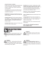
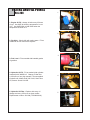
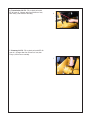
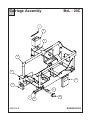
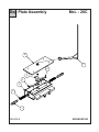
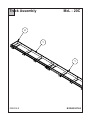
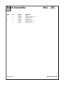
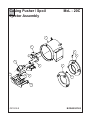
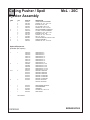
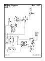
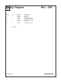
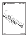
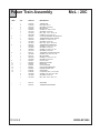
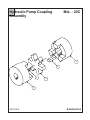
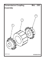
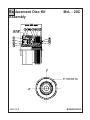
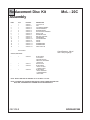
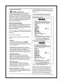
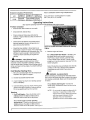
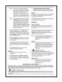
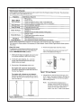
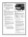
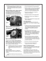
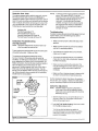
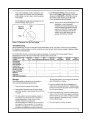
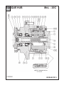
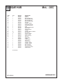
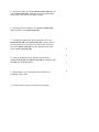
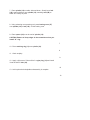
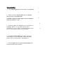
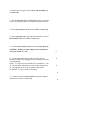
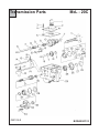
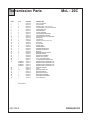
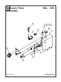
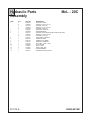
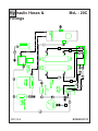
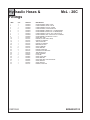
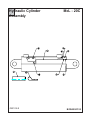
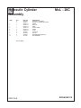
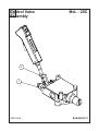
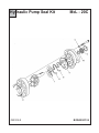
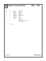
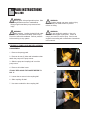
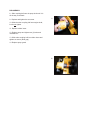
COMPONENTS AND
REPAIR MANUAL
MODEL McL-20C
EARTH BORING MACHINE
PART NO. 2050000
Machine Serial # ___________________________
Purchased &
Serviced Thru:
Repair Manual Part No.:
E250115
___________________________
Purchased Date: ___________________________
TABLE OF CONTENTS
Specs&Maintenance.............................................................................................2-3
Filters & Fill Points........................................................................................................4-5
Carriage Assembly.........................................................................................................6-7
Dog Plate Assembly.......................................................................................................8-9
Track Assembly......................................................................................................10-11
Casing Pusher/Spoil Ejector..............................................................................................12-13
Wiring Diagram....................................................................................................14-15
Power Train Assembly..........................................................................................................16-17
Hydraulic Pump Coupling.......................................................................................18-19
Transmission Coupling...........................................................................................20-21
Replacement Disc. Seal & Bearing Kits.............................................................22-23
Maintenance Record............................................................................................24-25
Engine Service & Maintenance..........................................................................26-41
Torque Hub............................................................................................................42-52
Maintenance Record............................................................................................53
Transmission Parts.............................................................................................54-55
Hydraulic Parts..................................................................................................56-57
Hydraulic Hoses & Fittings..................................................................................58-59
Hydraulic Cylinder................................................................................................60-61
Control Valve........................................................................................................62-63
Hydraulic Pump Seal Kit.......................................................................................64-65
Repair Instructions...............................................................................................68-75
Warranty, Return Goods Policy............................................................................76-77
© 1990 by McLaughlin Manufacturing Company, reprinted 2000
All rights reserved. No part of this manual may be reproduced in any form or by any
means without prior permission of McLaughlin Manufacturing Company.
Revision Date: 011810
SPECS & MAINTENANCE
McL-20C
SPECIFICATIONS OF MCL-20B
EARTH BORING MACHINE
Tunnel Diameter
Free Bore
Cased Bore
Planetary Final Drive
Hex Size
ENGLISH
METRIC
3” - 12” 7.6 cm - 30.5 cm
4” - 20” 10.2 cm - 50.8 cm
2-1/4”
5.7 cm
14-1/4”
29”
50”
1285#
36.2 cm
73.6 cm
127 cm
584 kg
Dimensions
Carriage and Pusher
Centerline Height
Width
Height
Weight
Master Track
Length
Weight
120”
330#
305 cm
140 kg
Extension Track
Length
Weight
120”
310#
305 cm
140 kg
16HP
S.A.E.
12kW
S.A.E.
42,000#
19,000 kg
Performance
Power Unit
Advance Thrust
@ 3,000 PSI
@ 207 BAR
Drive Chuck Speed
@ 3600 engine RPM
3rd Gear
2nd Gear
1st Gear
Reverse
Drive Chuck Torque
@ 2600 engine RPM
3rd Gear
2nd Gear
1st Gear
Reverse
100 RPM
53 RPM
32 RPM
26 RPM
100 RPM
53 RPM
32 RPM
26 RPM
REPAIR AND MAINTENANCE / GENERAL
Carriage/Tightness of Nuts and Bolts
Check bolts that mount chuck to the drive shaft flange of the
machine initially, then check each week when in continuous
use. Each bolts should have lock washer. Tighten as
needed.
Check all hydraulic fittings initially then check each week
when in continuous use. Tighten as needed, taking care
not to twist hoses from original positions.
Check bolts (4) on cam rollers inititally then once each
month when in continuous use. Tighten as needed. Check
and torque all bolts in engine mounts, transmission, planetary, flexible coupling and pump mount every 50 hours.
See parts and service manual for proper bolt torque specifications.
Carriage/Miscellaneous
Once a month, inspect the hitch pins (also called auger
pins, R. clips, R. pins) that hold the clevis pins in place.
Replace if worn or damaged.
Also, check clevis pins that hold machine down in place.
Replace if worn or damaged.
After each boring operation is completed, clean the carriage
to remove dirt and mud. Use water if available. Always
clean the unit before storage.
Track/General Maintenance
Check the rolling surfaces of the track for dirt or contamination. Clean as required. Tighten push plate bolts periodically. Always inspect bolts before boring begins.
Inspect the track for fractures and reweld as necessary.
1008 ft lbs.
1872 ft lbs.
3132 ft lbs.
3780 ft lbs.
1366 NM
2538 NM
4247 NM
5125 NM
Engine/General Maintenance
Review the engine manual supplied before starting and
operating the engine. Follow manufacturer’s recommendations for operation and manintenance to maintain your
engine warranty.
Check fluid levels as follows:
Engine Check oil level daily, fill with seasonal grade
oil as recommended in manufacturers manual
provided. Change oil per engine manufacturers
recommendation.
Transmission Fill to check point with EP 90 gear
oil, change after first 50 hours of use, then every
1000 hours or annually.
Final Drive Fill to check point with EP 90 gear oil,
change after first 50 hours of use, then every 1000
hours or annually.
Hydraulic Reservoir Fill (with cylinders retracted)
with 300SSU oil, change oil after first 1000 hours of
use, then annually. Recommended Hydraulic Oils,
Mobile Fluid 350 or 423, Shell Tellus 29, Sunoco
Sunvis 831-WR.
Hydraulic Filter Replace with every oil change and
every 750 hours or three months.
Dog Plate Oil all members, including dogs, initially
and then weekly when in continuous use. A light
machine oil or spray lubricant is recommended. It is
also recommended that the dog plate be disassembled and cleaned periodically, especially after
use in sticky clay conditions or sand.
Fuel Refer to engine manual supplied for gasoline
or diesel grade recommendations.
Auger Couplings Clean and coat with light oil after
every use.
Cutting Heads Examine all teeth and replace as
necesary before use. Check all conical bits on rock
heads for rotary freedom. Check condition and
freedom of wing cutters.
Auger Examine after use for fractures and reweld
as necessary.
NOTE: USE ONLY GENUINE McLAUGHLIN
REPLACEMENT PARTS.
REPAIR INSTRUCTIONS
McL-20C
WARNING:
Moving parts. Keep all guards in place. Shut
down engine before service or maintenance.
Being caught in machinery may cause serious
injury.
WARNING:
Crushing weight can cause serious injury.
Place mahine on solid surface to prevent
rollover or falling.
WARNING:
High pressure. Leaking hydraulic fluid under
pressure can penetrate and cause serious injury.
Check for leaks with card board. Relieve pressure
before working on any system.
WARNING:
Do not modify this machine. Use only
authorized McLaughlin repair parts. Failure
to comply can result in serious injury. Service this
equipment according to maintenance instructions in
this manual.
FILTERS AND FILL POINTS
McL-20C
1
1. Engine Oil Fill - change oil after every 25 hours
of use. Use SAE 30 when the temperature is over
32°F. Use SAE 5W20 or SAE 5W30 when the
temperature is below 32°F.
2
2. Dip Stick - Check daily with engine warm. Fill as
needed to the full mark on the dip stick.
3
3. Fuel Level - Fill as needed with branded grades
of gasoline.
4. Hydraulic Oil Fill - Fill as needed (with cylinders
retracted) with 300SSU oil. Change oil after first
1,000 hours of use, then annually. Recommended
Hydraulic oils: Mobile Fluid 350 or 423, Shell Telus
29, Sunoco Sunvis 831-WR.
4
5. Hydraulic Oil Filter - Replace with every oil
change and every 350 hours or three months.
Replacement number: 921-999 (T700090 McL#).
5
6. Transmission Oil Fill - Fill to check point with
EP 90 gear oil. Change after first 50 hours of use,
then every 1,000 hours or annually.
6
7. Planetary Oil Fill - Fill to check point with EP 90
gear oil. Change after first 50 hours of use, then
every 1,000 hours or annually.
7
Carriage Assembly
McL - 20C
1
2
3
4
5
11
6
9
7
082009-E
8
10
BORASSY002
Carriage Assembly
ITEM
1
2
3
4
5
6
7
8
9
10
11
QTY
1
2
1
1
2
2
2
2
1
1
2
1
2
2
2
4
4
4
4
4
4
1
4
4
4
4
082009-E
PART NO.
2011115
U130020
X400040
2050115
U000400
U210060
U000810
U210100
2099006
2011144
U000020
2011140
U000440
U100060
U210060
2099035
U340045
2099034
U340045
W000075
2099017
8030689
U000040
U200020
U230040
U120100
McL - 20C
DESCRIPTION
BATTERY HOLD DOWN
NUT, WING .312 - 18
BATTERY, SP-35
COUPLING GUARD
SCREW, HC .375 - 16 X .750
WASHER, LOCK .375
SCREW, HC .500 - 13 X .750
WASHER, LOCK .500
CARRIAGE WELDMENT
PUMP GUARD
SCREW, HC .250 - 20 X .500
HYD. PUMP MOUNT BRACKET
SCREW, HC .375 - 16 X 1.25
NUT, HEX .375 - 16
WASHER, LOCK .375
PIN, CLEVIS .745 X 4.9375”
PIN, R-CLIP
PIN, L .500 X 4.5”
PIN, R-CLIP
2 1/2” CAM ROLLER W/ 1”DIA STUD
HOLD DOWN - WELDMENT
BOX, PLASTIC for SAFETY MANUAL
SCREW, HC .250 - 20 X .75
WASHER, FLAT .250
WASHER, RUBBER .250
NUT, LOCK .250 - 20
BORASSY002
Dog Plate Assembly
McL - 20C
6
7
4
5
4
3
2
1
082609-E
BORASSY003
Dog Plate Assembly
ITEM
1
2
3
4
5
6
7
QTY
2
2
1
2
2
2
2
2
1
1
2
2
1
4
4
1
1
1
1
082609-E
PART NO.
2020020
U600040
2020010
U020060
U210100
U100120
2020050
U000815
2020040
T500020
U000815
U120100
2020060
U000960
U210100
2020070
U000400
U100060
U410055
McL - 20C
DESCRIPTION
DOG PIN
SPRING, COMP .105 X 1.06 X 4.25
DOG PLATE HOUSING
SCREW, SQ .500-13 X 2.00
WASHER, LOCK .500
NUT, HEX .500-13
LINKAGE ARM
SCREW, HC .500-13 X 1.00
LINKAGE SHIFTER
FITTING, GREASE .125 STRAIGHT
SCREW, HC .500-13 X 1.00
NUT, LOCK .500-13
TOP COVER PLATE
SCREW, HC .500-13 X 4.00
WASHER, LOCK .500
OPERATOR LEVER
SCREW, HC .375-16 X .750
NUT, HEX .375-16
KEY, STR .250 X .250 X 1.00
BORASSY003
Track Assembly
McL - 20C
2
1
1
082809-E
BORASSY004
Track Assembly
ITEM
1
2
QTY
3
8
8
8
1
4
4
4
082809-E
PART NO.
2040000
U000860
U100120
U210100
2040060
U000860
U100120
U210100
McL - 20C
DESCRIPTION
TRACK
SCREW, HC .500-13 X 1.75
NUT, HEX .500-13
WASHER, LOCK .500
THRUST PLATE
SCREW, HC .500-13 X 1.75
NUT, HEX .500-13
WASHER, LOCK .500
BORASSY004
McL - 20C
Casing Pusher / Spoil
Ejector Assembly
1
2
6
8
4
3
10
9
11
7
6
5
091509-E
BORASSY005
Casing Pusher / Spoil
Ejector Assembly
ITEM
1
2
3
4
5
6
QTY
1
4
4
2
3
1
1
5
5
1
1
1
1
3
PART NO.
2050041
U001355
U210160
U320015
U020120
2050101
A200440
U000860
U210100
U001510
U120040
R800545
2050051
U020120
McL - 20C
DESCRIPTION
CASING PUSHER ASSEMBLY
SCREW, HC .750 - 10 X 1.25”
WASHER, LOCK .750
PIN, COTTER .125 X 1.00
SCREW, SQ .750 -10 X 2.00
PADDLE ASSEMBLY COMPLETE
2.25 HEX - CHUCK ASSEMBLY
SCREW, HC .500 - 13 X 1.750
WASHER, LOCK .500
SCREW, HC .750 - 10 X 4.50
NUT, NY .750-10
CHUCK EXTENSION 2.250 TO 2.250
SADDLE ASSEMBLY
SCREW, SQ .750 - 10 X 2.00”
Optional Equipment:
(Available upon request)
7
1
2
A200040
A200060
A200080
A200100
A200120
A200140
A200160
A200180
A20004P
A20006P
A20008F
A20010P
A20012P
2090110
2090120
2090130
2090140
2090150
2090160
2013045
ADAPTER KIT, 4”
ADAPTER KIT, 6”
ADAPTER KIT, 8”
ADAPTER KIT, 10”
ADAPTER KIT, 12”
ADAPTER KIT, 14”
ADAPTER KIT, 16”
ADAPTER KIT, 18”
ADAPTER KIT, 4” PVC
ADAPTER KIT, 6” PVC
ADAPTER KIT, 8” PVC
ADAPTER KIT, 10” PVC
ADAPTER KIT, 12” PVC
SPACER 4” ADAPTER
SPACER 6” ADAPTER
SPACER 8” ADAPTER
SPACER 10” ADAPTER
SPACER 12” ADAPTER
SPACER 14” ADAPTER
SHOE 16” ADAPTER
SHOE 18” ADAPTER
8
1
9-10
4
11
*
*
1
1
1
2
1
2050149
2013070
2013080
U320015
2050160
REPLACEMENT DOOR KIT
DOOR WELDMENT
HINGE ROD
COTTER PIN, .125 X 1.00
SEAL SHIELD
*
NOT SHOWN
091509-E
BORASSY005
3
011910-E
4
1
-
+
2
BATTERY
OIL SENTRY
SHUTDOWN
NC
A
R
S
B
VIOLET
NO
RED
SOLENOID
NO
BLUE
KEYSWITCH
G
M
EMERG.
STOP
SWITCH
NC
6
B+
YELLOW
FLYWHEEL
STATOR
REGULATOR
STARTER
WHITE
FUSE
5
YELLOW
10AMP
BLACK
JOYS
JO
YSTIC
TICK
SPARK
PLUG
SOLEN
SO
LENOID
CLUTCH
Wiring Diagram
McL - 20C
BORASSY016
McL - 20C
Wiring Diagram
ITEM
1
2
3
4
5
6
QTY
1
1
1
1
1
1
PART NO.
X000020
X400040
X300140
X300150
J700100
X000090
DESCRIPTION
STOP SWITCH
BATTERY
CABLE, BATTERY (neg.)
CABLE, BATTERY (pos.)
PISTOL GRIP - COMPLETE
KEY SWITCH
*
1
X000013
STOP SWITCH BUTTON
*
NOT SHOWN
011910-E
BORASSY016
Power Train Assembly
McL - 20C
HYDRAULIC
PUMP
15
13
14
10
11
8
7
6
5
4
12
3
2
9
121609-E
1
BORASSY006
Power Train Assembly
ITEM
QTY
PART NO.
DESCRIPTION
1
1
9
9
1
2
2
1
1
1
1
4
4
4
1
2
2
2
2
1
4
1
4
4
1
1
1
1
1
1
1
1
4
4
1
P300000
U100190
U210140
P330000
U000820
U210100
U410092
W200160
T260008
2050120
U000760
U210080
U410061
2050155
U000760
U210080
U000840
U210100
2050113
U010080
2050112
U000760
U210080
2050091
2050099
2050092
P240001
2099001
2060000
P400003
P400000
U010080
U210060
U410060
TORQUE HUB
NUT, HEX .625-11
WASHER, LOCK .625
INPUT SHAFT
SCREW, HC .500-13 X .56
WASHER, LOCK .500
KEY, STR. .313 X .313 X .56
O-RING 4.0 X 4.18 X .103
COUPLING, ELEMENT- DELRIN CHAIN
TRANSMISSION OUTPUT SHAFT
SCREW, HC .438-14 X 1.25
WASHER, LOCK .438
KEY STR. .250 X .250 X .56
TRANSMISSION, MODEL #14
SCREW, HC .438-14 X 1.25
WASHER, LOCK .438
SCREW, HC .500-13 X 1.50
WASHER, LOCK .500
TRANS/ BELL HOUSING SPACER
SCREW, HSH .375-16 X 1.00
BELL HOUSING
SCREW, HC .438-14 X 1.25
WASHER, LOCK .438
CLUTCH, HYD
INSPECTION COVER
DRIVE CAP
CLUTCH SPACER
CLUTCH ADAPTER SHAFT
ENGINE, KOHLER 15HP
STUB SHAFT
COUPLING, HALF 1” X 1/4” KEY
SCREW, HSH .375-16 X 1.000
WASHER, LOCK .375
KEY, STR. .250 X .250 1.25
1
2
2050114
2050156
SNAP RING
TRANSMISSION SPACERS
2
3
4
5
6
7
8
9
10
11
12
13
14
15
*
*
121609-E
McL - 20C
BORASSY006
Hydraulic Pump Coupling
Assembly
McL - 20C
1
5
4
2
3
091509-E
BORASSY006
Hydraulic Pump Coupling
Assembly
ITEM
1
2
3
4
5
QTY
1
1
1
1
1
091509-E
PART NO.
P400000
P400002
P400001
U410015
U410055
McL - 20C
DESCRIPTION
COUPLING HALF
COUPLING INSERT
COUPLING HALF .625 BORE
KEY, STR. .125 X .125 X .625
KEY, STR. .250 X .250 X 1.00
BORASSY006
Transmission Coupling
Assembly
McL - 20C
3
1
2
092109-E
BORASSY008
Transmission Coupling
Assembly
ITEM
1
2
3
QTY
1
1
1
1
1
092109-E
PART NO.
T260008
T260006
U410060
T260007
U410140
McL - 20C
DESCRIPTION
DELRIN CHAIN
COUPLING, 1.00 BORE
KEY, STR. .250 X .250 X 1.25
COUPLING, 1.375 BORE
KEY, STR .375 X .375 X 2.00
BORASSY008
Replacement Disc Kit
Assembly
092109-E
McL - 20C
BORASSY009
McL - 20C
Replacement Disc Kit
Assembly
ITEM
1
2
3
4
5
6
7
8
9
10
11
12
13
14
15
QTY
1
1
1
1
5
6
1
1
6
1
1
1
1
1
1
1
*
NOT SHOWN
PART NO.
2050091
2050091-1
2050091-2
2050091-3
2050091-4
2050091-5
2050091-6
2050091-7
2050091-8
2050091-9
2050091-10
2050091-11
2050091-12
2050091-13
2050091-14
2050091-15
DESCRIPTION
CLUTCH, HYD
HUB
CYLINDER ASSEMBLY
PISTON ASSEMBLY
SEPARATOR DISC
FRICTION DISC ASSEMBLY
BACK PLATE
PRESSURE PLATE
BELLEVILLE SPRING
HUB BEARING
THRUST BEARING
O-RING
O-RING
RETAINING RING
RETAINING RING
INLET PORT CAP
Clutch Pressure: 100 psi
Use 0-300 psi gauge
CLUTCH, HYD. KITS:
*
1
2050093
*
*
1
1
2050147
2050094
*
1
2050095
KIT INCLUDES:
6 LUG DISCS
5 SPACER PLATES
6 BELLEVILLE SPRINGS
1 CIRCULAR
FRONT PLATE
KIT INCLUDES:
1 SMALL O-RING
1 LARGE O-RING
KIT INCLUDES:
1 SMALL BEARING
1 LARGE BEARING
1 SNAP RING
NOTE: INSTALL BELLEVILLE SPRINGS I.D. TO I.D. AND O.D. TO O.D.
NOTE: FOR SERIAL NO. 20062993536 AND HIGHER. CONSULT MANUFACTURER FOR
DISK, SEAL, AND BEARING KIT ASSEMBLES ON EARLIER MODELS.
092109-E
BORASSY009
MAINTENANCE RECORD
McL-20C
DATE
SERVICE PERFORMED
BY
____________
______________________________________________
_______________
____________
______________________________________________
_______________
____________
______________________________________________
_______________
____________
______________________________________________
_______________
____________
______________________________________________
_______________
____________
______________________________________________
_______________
____________
______________________________________________
_______________
____________
______________________________________________
_______________
____________
______________________________________________
_______________
____________
______________________________________________
_______________
____________
______________________________________________
_______________
____________
______________________________________________
_______________
____________
______________________________________________
_______________
____________
______________________________________________
_______________
____________
______________________________________________
_______________
____________
______________________________________________
_______________
____________
______________________________________________
_______________
____________
______________________________________________
_______________
____________
______________________________________________
_______________
____________
______________________________________________
_______________
____________
______________________________________________
_______________
____________
______________________________________________
_______________
____________
______________________________________________
_______________
____________
______________________________________________
_______________
PAGE LEFT BLANK
TORQUE HUB
121609-E
McL - 20C
BORASSY015
McL - 20C
TORQUE HUB
ITEM
1A
1B
1C
1D
1E
1F
1G
1H
1I
1J
1N
1P
1Q
2
3A
3B
3C
3D
3E
3F
3G
4
5
6
8
9
10
11
12
13
20
25
QTY
1
1
1
1
1
1
1
1
1
2
9
1
1
1
1
6
96
3
3
3
3
1
2
1
1
1
1
2
8
4
1
4
*
NOT SHOWN
121609-E
PART NO.
P301002
P300003
P300004
P300005
P300006
P300007
P301005
P300009
P300010
P300030
P301007
P301006
P301003
P300012
P300014
P300015
P300016
P300017
P300018
P300019
P301004
P300021
P300022
P300023
P300024
P300025
P300026
P300027
P300028
P300029
P300030
P300032
DESCRIPTION
SPINDLE
SEAL, LIP
BRG, TAPERED CUP
BRG, TAPERED CONE
BRG, TAPERED CUP
BRG, TAPERED CONE
HOUSING
WASHER, THRUST
RETAINING, RING-EXT
PIPE PLUG STD-NPTF
STUD
PIPE PLUG MAGN-NPTF
SEAL, BOOT
GEAR, INTERNAL
CARRIER
WASHER, THRUST-TANGED
BRG, NEEDLE
SPACER, THRUST
SHAFT, PLANET
GEAR, CLUSTER
PIN, ROLL
GEAR, RING
O-RING
COVER, INPUT
GEAR, SUN
SPACER, INPUT
WASHER, THRUST
WASHER, THRUST
BOLT, HEX UNC
BOLT, SHOULDER
PIPE PLUG, STD-NPTF
SCREW, DRIVE
BORASSY015
DISASSEMBLY
McL-20C
1. Drain oil from unit and discard.
2. Pressure test unit at 8 PSI for 10 minutes. Seal
and O-ring check.
3. Mark housing from bolt head down O.D. of cover
across ring gear to hub O.D. This is necessary
especially if rebuilding on machine.
4. Remove four (4) shoulder bolts and eight (8)
grade bolts from cover (items 12 & 13).
5. Remove cover (item #6).
6. Remove thrust washer (item #10) and thrust
washer (item #11).
7. Remove input sun gear (item #8).
8. Remove O-ring between cover and ring gear.
9. Remove ring gear (item #4).
10. Remove carrier sub-assembly (item #3A).
11. Remove O-ring (item #11) between ring gear
and hub counter bore.
12. Remove thrust washer (item #11) between
carrier housing and internal gear.
13. Remove internal gear (item #2).
14. Remove retaining gear (item #1T) from hub/
spindle sub-assembly and throw away. This requires retaining ring pliers. NOTE: Do not reuse
retaining ring. It might require that the bearing be
tapped down to remove the interference of press fit.
15. Remove bearing spacer (thrust washer) (item
#1H).
16. Place hub/spindle under a press and push
spindle out of hub. NOTE: Both bearing cones are
press fit.
17. When spindle comes out of hub, the seal (item
#1B) and bearing cone (item #1D) will be attached.
A bearing puller must be used to remove cone. Do
not reuse bearing cone or seal at this area.
18. Remove bearing cone from hub (item #1F).
19. Remove seal boot (item #1Q).
20. Place hub on table - using a grade ‘5’ bolt,
ground to a flat side, tap one cup out. Turn hub
over and tap other cup out.
Upon repair, install new cups and cones, seal
retaining ring for hub/spindle sub-assembly and new
O-rings. NOTE: Take care to time carrier
sub-assembly per building procedures. If carrier is
mistimed, gear teeth will fail in a short amount of
operating hours. Failure mode will be same as
torque overload which is bi-directional bending
fatigue in the cluster gears.
If disassembling the carrier sub-assembly, simply
tape the roll pins into the planet shaft (roll pins will
self contain in the planet shaft) tap planet shaft out
of carrier housing.
TORQUE HUB ASSEMBLY
McL-20C
CARRIER SUB-ASSEMBLY
1. Grease the inside of small end of one cluster gear (3F) and
line the inside of small end of cluster gear (3F) with 16 needle
rollers (3C).
1
2
2. Place spacer (3D) on top of needle rollers (3C) inside
cluster gear (3F).
3
3. Grease the inside of large end of cluster gear (3F) and line
the inside of large end of cluster gear (3F) with 16 needle
rollers (3C).
4. Stand carrier housing (3A) on its side. Starting from the
roll-pin-holed side of carrier, insert a planet shaft (3E), roll pin
hole last, into one of the planet shaft holes in carrier housing
(3A).
4
5. Grease and place one tanged thrust washer (3B) onto the
end of planet shaft (3E), inserting tang of the thrust washer
into the slot in the side of the carrier housing.
6. Following the thrust washer, oil assembled cluster gear
(3F) and place it onto planet shaft (3E).
7. Following the planet gear, grease and place one more
thrust washer (3B) onto planet shaft (3E), inserting tang of
the thrust washer into the slot in the side of carrier housing.
Now insert planet shaft (3E) into the opposite planet shaft
hole in carrier housing (3A).
5
6
8. Using an alignment punch, align the roll pin holes in
carrier housing (3A) and planet shaft (3E) and hammer roll
pin (3G) into the aligned holes.
9. Repeat steps 1 to 8 to assemble and install the two
remaining cluster gears.
10. At this point the carrier sub-assembly is complete.
7
8
HUB-SPINDLE SUB-ASSEMBLY
NOTE: Make sure the cup sits square with the counterbore
before pressing.
1. Set hub (1G) on work surface, wide end up. Using a
bearing cup pressing tool, press bearing cup (1E) into the
counterbore in the wide end of hub (1G). Oil the bearing
cup.
NOTE: Make sure the cup sits square with the counterbore
before pressing.
2. Using a bearing cup pressing tool, press bearing cup
(1C) into the counterbore in the small end of hub (1G). Oil
the bearing cup.
3. Place bearing cone (1D) into the small end of hub (1G).
Oil the bearing cone.
1
4. Using a seal pressing tool, press seal (1B), closed side
facing up, into the small end of hub (1G). Oil the seal.
5. Press studs (1N) into the holes in flange of hub (1G).
Reinstall seal boot (1Q) onto the hub (1G). (Ref. drawing
pg. 56). Replace seal if damaged or missing.
2
3
4
6. Apply a light coat of “Never-Seize” to pipe plug (1P) and
install it into the bottom (wide end) of spindle (1A).
6
7. Place spindle (1A) on table, wide end down. Slowly lower hub
(1G), small end down, onto spindle (1A), watching seal (1B) to
make sure it stays in place.
8. Using a bearing cone pressing tool, press bearing cone (1F)
onto spindle (1A) in hub (1G). Oil the bearing cone.
9. Place spacer (1H) over the end of spindle (1A).
CAUTION: Beware of sharp edges in the counterbore when you
install “O” ring.
7
10. Place retaining ring (1I) over spindle (1A).
8
11. Check endplay.
9
12. Apply a light coat of “Never-Seize” to pipe plug (1J) and install
it into the side of hub (1G).
10
13. At this point the hub-spindle sub-assembly is complete.
12
MAIN ASSEMBLY
1
1. Lower internal gear (2), small end down, into hub (1G).
2
2. Grease and place thrust washer (11) into internal
gear (2) and around spindle (1A).
CAUTION: Beware of sharp edges in the counterbore
when you install “O” ring.
3
4
3. Grease and place “O” ring (5) into the counterbore of
hub (1G). NOTE: “O” ring can be stretched to fit
counterbore (if it is too small), or squeezed together bit by
bit (if it is too large) to make “O” ring fit exactly.
4. Set carrier sub-assembly (3) on table, large gear
ends facing up. Line up the punch marks on the gear
teeth to the 12 o’clock position. See Diagram 1.
5. Place ring gear (4) onto carrier sub-assembly (3) to
keep the punch marks in position.
5
6. Holding onto ring gear, lower carrier sub-assembly (3)
into hub (1G).
7. Now lift ring gear (4) off of hub (1G) and line up the bolt
holes in hub and ring gear, then replace ring gear into hub.
8. Place thrust spacer (9) down into middle of carrier (3).
9. Place input gear (8), larger splined end down, on top of
thrust spacer (9) in the middle of carrier (3).
10. Place thrust washer (10) down around input gear (8).
CAUTION: Beware of sharp edges in the counterbore
when you install “O” ring.
11. Place cover (6) on work surface, interior side up.
Grease and place “O” ring (5) into the counterbore around
rim of cover (6).
NOTE: “O” rings may be stretched to fit counterbore. If an
“O” ring has been stretched too much, simply squeeze the
“O” ring together bit by bit as you place it around the
counterbore. It can be made to fit exactly.
6
8
9
11
12. Grease and place thrust washer (11) around edge of
raised circular center of cover (6).
12
13. Lower cover (6), interior side down, onto ring gear (4),
aligning the bolt holes in cover and ring gear. See you
assembly print for pipe plug timing.
14. Place shoulder bolts (13) into their holes in cover (6)
and tighten by hand.
13
15. Place bolts (12) into their holes in cover (6) and tighten.
14
16. Apply 23-27 ft.-lbs. of torque to each shoulder bolt (13).
15
17. Apply 23-27 ft.-lbs. of torque to each bolt (12).
16
18. Apply a light coat of “Never-Seize” to pipe plug (20) and
install it into the pipe plug hole in cover (6).
18
19. Roll test the unit in both clockwise and
counterclockwise directions. Perform the same number of
turns in each direction as the ratio of the unit. This number
is the same as the last two digits in the model number
found on the ID tag of the unit. For example, if the model
number of this unit is S1B1003369, then roll the unit 69
times in each direction.
19
20. Lead test the unit at a pressure of 5 PSI for 2-3
minutes.
20
21. At this point the main assembly is complete.
MAINTENANCE RECORD
McL-20C
DATE
SERVICE PERFORMED
BY
____________
______________________________________________
_______________
____________
______________________________________________
_______________
____________
______________________________________________
_______________
____________
______________________________________________
_______________
____________
______________________________________________
_______________
____________
______________________________________________
_______________
____________
______________________________________________
_______________
____________
______________________________________________
_______________
____________
______________________________________________
_______________
____________
______________________________________________
_______________
____________
______________________________________________
_______________
____________
______________________________________________
_______________
____________
______________________________________________
_______________
____________
______________________________________________
_______________
____________
______________________________________________
_______________
____________
______________________________________________
_______________
____________
______________________________________________
_______________
____________
______________________________________________
_______________
____________
______________________________________________
_______________
____________
______________________________________________
_______________
____________
______________________________________________
_______________
____________
______________________________________________
_______________
____________
______________________________________________
_______________
____________
______________________________________________
_______________
Transmission Parts
092109-E
McL - 20C
BORASSY013
Transmission Parts
ITEM
1
2
3
4
5
6
7
8
9
10
11
12
13
14
15
16
17
18
19
20
21
22
23
24
25
26
27
28
29
30
31
32
33
34
35*
QTY
1
1
6
6
1
1
4
2
1
1
1
1
5
2
2
2
2
1
1
2
2
1
1
1
1
1
AS REQ’D
AS REQ’D
AS REQ’D
AS REQ’D
1
1
14
1
1
1
4
1
*
NOT SHOWN
092109-E
PART NO.
2400186
2400187
2400188
2400189
2400190
2400191
2400192
2400193
2400194
2400195
2400196
2400197
U000400
2400199
2400200
2400201
2400202
2400203
2400204
2400205
2400206
2400207
2400208
2400209
2400210
2400211
2400212
2400213
2400214
2400215
2400216
2050136
2400218
2050137
2400220
2400221
2400222
2050132
McL - 20C
DESCRIPTION
SHIFT COVER CAP
SHIFT COVER
SCREW, HHCS .312-18 X .875
LOCKWASHER, .312 EXT. TOOTHED
INTERLOCK PLATE
COUNTERSHAFT
THRUST WASHER
COUNTERSHAFT BEARING
COUNTERSHAFT SPACER
COUNTERSHAFT CLUSTER GEAR
MAINSHAFT
LOCKPLATE
SCREW, HCS .375-16 X .750
SHIFT RAIL
SHIFT FORK
DETENT BALL
DETENT SPRING
REVERSE IDLER SHAFT
REVERSE IDLER GEAR
BEARING
BEARING/CASE SNAPRING
BEARING SPACER
MAINSHAFT RETAINER
MAINSHAFT OILSEAL
2nd & 3rd SLIDING GEAR
1st & REVERSE SLIDING GEAR
BEARING/SHAFT SNAPRING .087
BEARING/SHAFT SNAPRING .090
BEARING/SHAFT SNAPRING .093
BEARING/SHAFT SNAPRING .097
BEARING SLINGER
CASE
MAIN DRIVE ROLLER
MAIN DRIVE GEAR
MAIN DRIVE OILSEAL
MAIN DRIVE RETAINER
MAIN DRIVE FASTENERS
SHIFT LEVER KIT
BORASSY013
Hydraulic Parts
Assembly
McL - 20C
5
CLEVIS PIN
AND CLIP PIN
2
3
1
4
11
6
8
14
12
13
9
10
7
091709-E
BORASSY007
Hydraulic Parts
Assembly
ITEM
1
2
3
4
5
6
7
8
9
10
11
12
13
14
QTY
1
2
2
2
2
1
1
1
3
6
1
1
2
1
1
1
1
2
1
1
091709-E
PART NO.
2050028
U000860
U210100
U000400
U210060
2050068
HD00092
2050170
U000140
U210020
J700100
2050145
2050165
2400127
T402159
T000320
T405062
T404030
T700080
2400371
McL - 20C
DESCRIPTION
HYDRAULIC TANK
SCREW, HC .500-13 X 1.75
WASHER, LOCK .500
SCREW, HC .375-16 X .750
WASHER, LOCK .375
HYDRAULIC TANK CAP
PRESSURE GAUGE
CONTROL VALVE (DOES NOT INCLUDE PISTOL GRIP)
SCREW, HC .250-20 X 2.50
WASHER, LOCK .250
PISTOL GRIP - COMPLETE
HYDRAULIC PUMP
HYDRAULIC CYLINDER
HYDRAULIC MANIFOLD
TEE, 1/2MP - 1/2MP - 1/2FP
VALVE, CHECK
PLUG, 1/2”NPT
UNION, 12MP - 8MP
FILTER ASSEMBLY
SOLENOID CONTROL VALVE
BORASSY007
Hydraulic Hoses &
Fittings
092109-E
McL - 20C
BORASSY012
Hydraulic Hoses &
Fittings
ITEM
1
2
3
4
5
6
7
8
9
15
16
17
18
19
20
21
22
23
24
25
26
27
28
29
30
31
32
33
QTY
1
1
1
2
2
2
1
1
1
1
1
1
1
1
1
3
6
4
1
1
1
2
1
2
1
1
1
1
092109-E
PART NO.
TH00053
TH00054
TH00059
TH00055
TH00052
TH00051
TH00057
TH00058
TH00050
T400070
T401670
T401300
T402150
T401320
T400700
T400160
T400140
T401140
2050109
T402156
T404030
T405060
T400800
T400550
T400028
T400010
T400020
T401015
McL - 20C
DESCRIPTION
HOSE ASSEMBLY, TANK - PUMP
HOSE ASSEMBLY, PUMP - VALVE
HOSE ASSEMBLY, VALVE - GAUGE
HOSE ASSEMBLY, VALVE MANIFOLD
HOSE ASSEMBLY, MANIFOLD - CYLINDER (BASE)
HOSE ASSEMBLY, MANIFOLD - CYLINDER (ROD)
HOSE ASSEMBLY, VALVE - ADJ. CHECK VALVE
HOSE ASSEMBLY, ADJ. CHECK VALVE - SOLENOID
HOSE ASSEMBLY, SOLENOID - CLUTCH
UNION, 8MP-12MJ
ELBOW, 90 12MB-12MJ (LONG)
ELBOW, 90 10MB-8MJ
TEE, 8FJ-8MJ-8MJ
ELBOW, 90 12MB-8MJ
REDUCER, 8FJ-4MJ
UNION, 10MB-8MJ
UNION, 8MB-8MJ
ELBOW, 90 8MP-8MJ
HTDRAULIC FITTING ASSY.
TEE, 8MP-8FP-8FP
UNION, 12MP-8MP
PLUG, 8MP
UNION, 12MP-12MP
UNION, 6MB-4MJ
UNION, 6MP-6MJ w/ #6 SAE O-RING
UNION, 2MP-4MJ
UNION, 4MP-4MJ
ELBOW, 45 4FP-4MP
BORASSY012
Hydraulic Cylinder
Assembly
092109-E
McL - 20C
BORASSY010
Hydraulic Cylinder
Assembly
ITEM
1
2
3
4
5
6
7
8
9
10
QTY
2
1*
1
1
1
1
1
2
2*
2*
1*
1*
*
PER CYLINDER
092109-E
PART NO.
2050165
2000010
2000010-1
2000010-2
2000010-3
2000010-4
2000010-5
2000010-6
T840080
G820050
2050065
T810040
McL - 20C
DESCRIPTION
HYDRAULIC CYLINDER
SEAL KIT, CYLINDER (INCLUDES)
O-RING
BACK-UP
WIPER
U-CUP LOADED
O-RING
U-CLIP
CLEVIS PIN
CLIP PIN
RETAINING RING HEAD CAP
ROD ASSEMBLY
BORASSY010
Control Valve
Assembly
McL - 20C
2
1
092109-E
BORASSY011
McL - 20C
Control Valve
Assembly
ITEM
1
2
QTY
1
1
092109-E
PART NO.
2050067
2050175
DESCRIPTION
RELIEF VALVE CARTRIDGE
VALVE HANDLE
BORASSY011
Hydraulic Pump Seal Kit
092309-E
McL - 20C
BORASSY014
Hydraulic Pump Seal Kit
ITEM
*
*
*
*
QTY
1
1
2
1
1
1
1
4
1
1
2
1
1
2
*
NOT SHOWN
7
8
9
10
12
13
17
40
092309-E
PART NO.
2050146
2050146-7
2050146-8
2050146-9
2050146-10
2050146-12
2050146-13
2050146-17
2050146-40
2000227
McL - 20C
DESCRIPTION
SEAL KIT
WEAR PLATE
O-RING
SHAFT SEAL
WASHER
BACKUP GASKET
SEAL
WASHER
PLUG
SEAL KIT
LOADED SEALS
SHAFT SEALS
SQUARE CUT RING (STATIC SEAL)
LOAD SEAL SPACER
BORASSY014
COLD WEATHER OPERATION
McL-20C
Cold weater effects the operation and performance of the boring machine.
Cold hydraulic fluid causes sluggish machine performance and can contribute to the premature failure of
some machine components.
Before starting to bore, the machine and hydraulic fluid must be at operating temperature (i.e. the machine
must be warmed-up before boring.)
Warm-up Procedure:
1. Start the machine and let it run at idle for 1-2 minutes.
2. Slowly increase the engine rpm to about 1/2 to 3/4 full throttle.
3. Allow the engine to run at this higher speed for 4-5 minutes.
4. Extend and retract the thrust cylinders to warm up the hydraulic fluid.
5. Occasionally running the machine over relief will help to reduce the warm-up time.
Only after the machine is warmed-up should you begin to bore.
Hydraulic Clutch Operation:
SLUGGISH OR DELAYED APPLY TIME FOR THE CLUTCH CAN CAUSE PREMATURE FAILURE.
The apply time for the clutch (the time it takes to build full pressure) is critical to the operation of the
machine. Normal clutch apply time is less than 2 seconds. If the apply time is greater than 2 seconds,
wait until oil temperature increases before boring.
Cycle the clutch during warm-up, waiting 10 seconds between engagements. WHEN APPLYING THE
CLUTCH DURING THE WARM-UP PERIOD, THE TRANSMISSION MUST BE IN NEUTRAL. Do not cycle
the clutch during warm-up while coupled to loaded augers.
Boring with an extended clutch apply time will cause premature failure of the clutch.
Hydraulic Fluid:
Use the alternate hydraulic fluid for the following:
To reduce warm-up time before boring.
When consistently boring in cold weather.
Standard hydraulic fluid: Iso grade #46 with anti-wear additives.
76 Unax AW#46, or equivalent
Alternate hydraulic fluid: Iso grade #32 Wide Temperature Range oil with anti-wear additives.
76 Unax AW-WR#32, or equivalent
Consult McLaughlin Mfg. Co. for more information.
NOTES
McL-20C
_______________________________________________________________________________________________________________________
__________________________________________________________________________________________________
_________________________________________________________________________________________________________
_________________________________________________________________________________________________________
_______________________________________________________________________________________________________
_________________________________________________________________________________________________________
___________________________________________________________________________________________________________
_________________________________________________________________________________________________________
_______________________________________________________________________________________________________
____________________________________________________________________________________________________________
_________________________________________________________________________________________________________
______________________________________________________________________________________________________________
________________________________________________________________________________________________________________________________
___________________________________________________________________________________________________________
______________________________________________________________________________________________________________
____________________________________________________________________________________________________________________
_________________________________________________________________________________________________________________
___________________________________________________________________________________________________________
_______________________________________________________________________________________________________________
________________________________________________________________________________________________________________
________________________________________________________________________________________________________________
____________________________________________________________________________________________________________
_____________________________________________________________________________________________________________
___________________________________________________________________________________________________________________
__________________________________________________________________________________________________________
_____________________________________________________________________________________________________________
REPAIR INSTRUCTIONS
McL-20C
WARNING:
Moving parts. Keep all guards in place. Shut
down engine before service or maintenance.
Being caught in machinery may cause serious
injury.
WARNING:
High pressure. Leaking hydraulic fluid under
pressure can penetrate and cause serious injury.
Check for leaks with cardboard. Relieve pressure
before working on any system.
WARNING:
Crushing weight can cause serious injury.
Place machine on solid surface to prevent
rollover or falling.
WARNING:
Do not modify this machine. Use only
authorized McLaughlin repair parts. Failure to
comply can result in serious injury. Service this
equipment according with maintenance instructions
in this manual.
HYDRAULIC PUMP COUPLING REPLACEMENT
DISASSEMBLY
1
1. Remove the pump guard.
2. Remove the tow (2) bolts and lockwashers that
attach the pump to the pump mount.
3. Slide the pump and coupling half out of the
pump mount.
4. Remove old rubber insert.
IF ONLY REPLACING THE INSERT REFER TO
NO. 11
3
5. Loosen the set screw in the coupling half.
6. Slide coupling off shaft.
7. Use same method for other coupling half.
5
REASSEMBLY
8. Slide coupling half onto the pump shaft until it is
all the way to the back.
9. Replace and tighten the set screw.
8
10. Slide the other coupling half onto engine shaft,
but do not tighten.
11. Replace rubber insert.
12. Replace pump and tighten two (2) bolts and
lockwashers.
13. Slide other coupling half into rubber insert and
tighten set screw. (Note gap)
14. Replace pump guard.
13
TRANSMISSION COUPLING REPLACEMENT
DISASSEMBLY
2
1. Disconnect the battery.
2. Remove the coupling guard.
3. Drive out the master link pin in the chain.
4. Remove the chain.
IF ONLY REPLACING THE CHAIN REFER TO NO.
13
3
5. Loosen the set screws in the sprocket hubs.
(Removal of the screw is not necessary).
6. Remove the nine (9) nuts that bolt the planetary
to the front plate.
7. Slide the planetary forward until coupling half
clears.
8. Remove the coupling halves.
5
REASSEMBLY
9. Slide the coupling halves onto the shafts. Make
sure the sprocket is flush with the end of the shaft.
10. Slide the planetary backward into its pilot.
11. Tighten the nine (9) nuts that bolt the planetary
to the front plate.
12. Tighten the set screws in the sprocket hubs.
7
13. Replace the chain.
14. Insert the master link pin in the chain.
15. Replace the coupling guard.
16. Connect the battery.
9
HYDRAULIC CLUTCH REPLACEMENT
DISASSEMBLY
Step 1: Transmission Coupling Removal
1. Follow the TRANSMISSION COUPLING
REPLACEMENT (Disassembly) instructions.
Step 2: Clutch Removal
2. Once the transmission coupling has been
removed, further breakdown of the power train can
be done.
3. Remove the six (6) bolts that hold the transmission in place. Remove transmission.
4. Remove bell housing inspection plate.
5. Disconnect the hydraulic hose at the clutch. Use
a male cap to block the hose. (NOT SUFFICIENTLY BLOCKING THE HOSE COULD RESULT
IN A LOSS OF HYDRAULIC FLUID).
6. Remove the bell housing.
3
7. Remove the clutch by pulling it straight out of the
drive shell.
4
IF TOTALLY REPLACING THE CLUTCH REFER
TO NO. 33
5
6
7
Step 3: Clutch Disassembly
Refer to the following steps for clutch disassembly:
Steps 8-10 Disk Kit Replacement
Steps 8-13 Seal Kit Replacement
Steps 8-15 Bearing Kit Replacement
8. Remove and discard the snap ring holding the
disks together. (NOTE: THE DISKS ARE UNDER
PRESSURE. THE DISKS MUST BE COMPRESSED BEFORE THE SNAP RING CAN BE
REMOVED. EYE PROTECTION MUST BE WORN
FOR SAFETY).
9. Once the snap ring is off, remove the front plate.
Remove and discard the following: six (6) belleville
springs, five (5) seperator disks, and six (6) friction
disks. (DO NOT DISCARD THE FRONT PLATE
OR PRESSURE PLATE).
10. Clean the front plate and pressure plate if
necessary. (MAKE SURE THAT BOTH PLATES
ARE COMPLETELY DRY BEFORE REASSEMBLING).
11. Support cylinder assembly, on bearing side, and
push down on hub. Remove and discard snap ring.
(EYE PROTECTION MUST BE WORN FOR
SAFETY).
12. Support clutch on pressure plate. Push down
on hub to remove from cylinder assembly.
13. Use low air pressure to separate cylinder
assembly from piston assembly and pressure plate.
Remove and discard o-rings. At this point, inspect
bearings for wear. If bearings are acceptable, refer
to step 23.
14. Remove the two (2) bearing removal plugs in
cylinder face. Use two (2) 1/4” diameter rods to tap
bearing out of cylinder counterbore. (NOTE: DO
NOT STRIKE THE COUNTERBORE WITH THE
RODS).
15. Remove the two (2) bearing removal plugs in
piston face. Use two (2) 1/4” diameter rods to tap
bearing out of piston counterbore. (NOTE: DO
NOT STRIKE THE COUNTERBORE WITH THE
RODS).
8
12
13
14
ASSEMBLY
Step 4: Clutch Assembly
Refer to the following steps for clutch assembly:
Steps 25-27 Disk Kit Assembly
Steps 19-28 Seal Kit Assembly
Steps 16-28 Bearing Kit Assembly
16. Install bearing removal plugs in the cylinder and
piston face. Apply a light coat of “Locktite” removable thread locker #242 (or equivalent) to the inner
and outer races of the bearings. (NOTE: APPLY A
FEW DROPS OF REMOVABLE THREAD SEALANT TO THE PLUGS. TIGHTEN PLUGS TO
“JUST BELOW” THE CYLINDER AND PISTON
FACES).
17. Press a new sealed bearing into cylinder by
pressing on the outer race of the bearing.
18. Press a new sealed bearing onto the pressure
plate by pressing on the inner race of the bearing.
19. Apply a light oil to all o-ring surfaces and
grooves before assembling the clutch. Install orings into the proper o-ring grooves.
20. Align the anti-rotation pin in the piston with the
blind hole in the cylinder. Carefully press the piston
onto the cylinder. As the piston o-ring begins to
slide onto the cylinder, it may be necessary to guide
the o-ring into the o-ring groove.
21. Assemble the pressure plate and bearing
assembly into the cylinder and piston assembly by
pressing on the pressure plate.
22. Assemble the hub into the cylinder assembly by
supporting hub on the splined end. Place the
cylinder assembly on the hub and press the bearing
onto the hub. (NOTE: PRESS ON THE INNER
RACE OF THE BEARING). As the bearing is being
pressed onto the hub, it is necessary to align the
internal spine of the pressure plate with the external
spline of the hub.
19
20
23. Install the retaining ring. (EYE PROTECTION
MUST BE WORN FOR SAFETY).
24. Seat the bearing against the retaining ring by
supporting pressure plate and pressing on the hub.
25. The reassembly order of the disk kit is as
follows:
1st - friction disk
2nd - belleville spring (O.D. facing pressure
plate)*
3rd - spacer plate
This order is repeated until all disks, springs and
spacer plates are in place.
*Note: Belleville Springs must be installed I.D. to
I.D. for proper clutch operation.
26. Install front plate and reinsert snap ring. (EYE
PROTECTION MUST BE WORN FOR SAFETY).
(NOTE: DISKS MUST BE COMPRESSED IN
ORDER TO HAVE ACCESS TO THE SNAP RING
GROOVE).
27. Rotate disks by hand to insure proper seating.
The disks should be evenly spaced.
28. Rotate the hub in the cylinder to insure that the
bearings are free.
25
ASSEMBLY
Step 5: Installing the hydraulic clutch fitting. (These
instructions are for use only if the fitting is being changed
or replaced).
29. Remove the hydraulic clutch fitting from the old
clutch.
30. Clean off any remaining sealant into the clutch and
tighten.
31. Apply a drop of removable thread sealant to the pipe
thread of the fitting. (NOTE: THE FITTING MUST BE
CLEAN AND DRY BEFORE ANY SEALANT CAN BE
APPLIED).
32. Install the fitting with the sealant into the clutch and
tighten.
Step 6: Installing the clutch
33. Line up the clutch disks with the slots in the drive
shell. The disks must be aligned one-at-a-time. (EXTRA
CARE MUST BE TAKEN WHEN INSTALLING THE
CLUTCH INTO THE DRIVE SHELL. ANY SUDDEN
MOVEMENT, SIDE-TO-SIDE OR UP AND DOWN, CAN
CAUSE THE TEETH OF THE DISKS TO BREAK OFF.
DO NOT FORCE THE DISKS INTO THE DRIVE SHELL).
34
34. Once all four (4) disks are fully in the drive shell, slide
the bell housing into its pilot on the engine, and tighten
bolts.
35
32
35. Connect the hydraulic hose to the clutch.
36. Replace the bell housing inspection plate.
38
37. Slide transmission input shaft into clutch. Replace
and tighten six (6) bolts for the transmission.
Step 7: Reinstalling the transmission coupling
38. Follow the Transmission Coupling Replacement
(Assembly) instructions.
Step 8: Machine Test (Before Starting Engine)
39. Check movement of transmission lever and engagement of all transmission gears.
Step 9: Machine Test
40.
41.
42.
43.
Start Engine
Check movement of transmission lever and engagement of all transmission gears.
Check clutch pressure with 0-300 psi gauge. (Pressure setting: 95 psi)
Check control valve pressure setting with 0-5000 psi gauge. (Pressure setting: 3000 psi)
WARRANTY/RETURN GOODS POLICY
McL-20C
McLAUGHLIN LIMITED WARRANTY
The Manufacturer warrants its products to be free from
defects in material and workmanship for a period of
twelve months from the date of shipment from the factory. The Manufacturer shall not be responsible for any
damage resulting to or caused by its products by reason of installation, improper storage, unauthorized service, alteration of the products, neglect, or abuse, or
use of the product in a manner inconsistent with its design. This warranty does not extend to any component
parts not manufactured by Manufacturer; however,
Manufacturer’s warranty herein shall not limit any warranties made by manufacturers of component parts
which may extend to Buyer.
Claims or defects in material and workmanship shall be
made in writing to Manufacturer within ten days of discovery of defect. Manufacturer may either send a service representative or have the product returned to its
factory at Buyer’s expense for inspection. Upon notification of defect, Manufacturer will issue a return good
authorization number to Buyer. The return goods authorization number must accompany the product returned. If judged by the Manufacturer to be defective in
material or workmanship, the product will be replaced
or repaired at the option of Manufacturer, free from all
charges except authorized transportation. Buyer shall
be responsible for all maintenance services consisting
of lubrication and cleaning of equipment, replacing expendable parts, making minor adjustments and performing operating checks, all in accordance with procedures
outlined in Manufacturer’s maintenance literature.
THE FOREGOING WARRANTY IS IN LIEU OF ALL
OTHER WARRANTIES, AND NO REPRESENTATIONS, GUARANTEES, OR WARRANTIES, EXPRESS
OF IMPLIED, (INCLUDING BUT NOT LIMITED TO, A
WARRANTY OF MERCHANTABILITY OR FITNESS
FOR A PARTICULAR PURPOSE,) ARE MADE BY THE
MANUFACTURER IN CONNECTION WITH THE
MANUFACTURE OR SALE OF ITS PRODUCTS. NO
EMPLOYEE, DISTRIBUTOR OR REPRESENTATIVE IS
AUTHORIZED TO CHANGE THIS WARRANTY IN ANY
WAY OR GRANT ANY OTHER WARRANTY ON BEHALF OF MANUFACTURER.
THE REMEDIES OF BUYER SET FORTH HEREIN ARE
EXCLUSIVE AND ARE IN LIEU OF ALL OTHER REMEDIES. THE LIABILITY OF MANUFACTURER
WHETHER IN CONTRACT, TORT, UNDER ANY WARRANTY, OR OTHERWISE SHALL NOT EXTEND
BEYOND ITS OBLIGATION TO REPAIR OR REPLACE,
AT ITS OPTION, ANY PRODUCT OR PART FOUND
BY MANUFACTURER TO BE DEFECTIVE IN MATERIAL OR WORKMANSHIP. MANUFACTURER SHALL
NOT BE LIABLE FOR COST OF INSTALLATION AND/
OR REMOVAL OR BE RESPONSIBLE FOR DIRECT,
INDIRECT, SPECIAL OR CONSEQUENTIAL DAMAGES OF ANY NATURE.
FOR SERVICE OR ASSISTANCE, SEE THE AUTHORIZED McLAUGHLIN DEALER IN YOUR AREA.
GENERAL RETURNS FOR MERCHANDISE
1. All material returned to McLaughlin Mfg. Company
must have a return authorization number. This number
can be obtained by calling the dealer from whom the
material was originally purchased.
2. All returned material must be shipped PREPAID.
3. Material without a material authorization number or
returned collect will be refused at our dock.
4. All material ordered incorrectly or new material returned for no valid reason will be subject to a 20% restocking charge.
5. In the case of warranty claims, a letter explaining the
problem or requesting repair must accompany the material.
6. On warranty consideration, all material shipped by
McLaughlin will be invoiced until the defective material
is returned for inspection. After inspection, credit will
be issued for all parts deemed defective.
7. All return authorized numbers expire 30 days after
issue. After this time, warranty claims and material returns are void, and merchandise must be paid in full.
8. McLaughlin must be notified and authorize all warranty work performed by your service personnel. This
authorization must be obtained PRIOR to any work being performed for proper warranty consideration. Credit
will not be issued for unauthorized service work performed.
NOTES
McL-20C
_______________________________________________________________________________________________________________________
__________________________________________________________________________________________________
_________________________________________________________________________________________________________
_________________________________________________________________________________________________________
_______________________________________________________________________________________________________
_________________________________________________________________________________________________________
___________________________________________________________________________________________________________
_________________________________________________________________________________________________________
_______________________________________________________________________________________________________
____________________________________________________________________________________________________________
_________________________________________________________________________________________________________
______________________________________________________________________________________________________________
________________________________________________________________________________________________________________________________
___________________________________________________________________________________________________________
______________________________________________________________________________________________________________
____________________________________________________________________________________________________________________
_________________________________________________________________________________________________________________
___________________________________________________________________________________________________________
_______________________________________________________________________________________________________________
________________________________________________________________________________________________________________
________________________________________________________________________________________________________________
____________________________________________________________________________________________________________
_____________________________________________________________________________________________________________
___________________________________________________________________________________________________________________
__________________________________________________________________________________________________________
_____________________________________________________________________________________________________________